Accton Technology AC1200 Dualband Outdoor AP, 802.11ac Outdoor Dual Band Access Point User Manual rev 3
Accton Technology Corp Dualband Outdoor AP, 802.11ac Outdoor Dual Band Access Point rev 3
User Manual rev 3.pdf

QuickStartGuide
802.11
acOutdoorStand‐AloneAccessPoint
SkyFire™AC1200andSkyFire™AC866
Brand:IgniteNet&Edge‐CorE
TheAC1200andtheAC866aresingle‐anddual‐bandaccesspoints(APs)thatare
housedinawaterproofenclosureformountingoutdoors.Theunitsincludeabuilt‐
inmountingbracketforattachingtoa1.5to6‐inchpoleandtheycanbepowered
throughtheirEthernetcableconnectionfromapowerinjectormodulethatis
installedindoors.
TheOutdoorStand‐AloneAccessPointsincludethesemodels:
◆
SF‐AC1200—dual‐bandw/integrated5GHzantennaand2xRP‐SMA(2.4GHz)
◆
SF‐AC1200‐1—dual‐bandw/2xRP‐SMA(5GHz)and2xRP‐SMA(2.4GHz)
◆
SF‐AC1200‐2
—dual‐bandw/integrated5GHzantennaand2.4GHzantenna
◆
ECWO5320—802.11acOutdoorDualBandAccessPoint
◆
ECWO5320‐L—802.11acOutdoorDualBandAccessPoint
◆
SF‐AC866
—single‐bandw/integrated5GHzantenna
◆
SF‐AC866‐1
—single‐bandw/2xRP‐SMA(5GHz)
Note:ForSafetyandRegulatoryinformation,refertotheSafetyandRegulatory
InformationdocumentincludedwiththeAP.
www.ignitenet.com

–
12
–
–
GettingStarted
Thissectionprovidesanoverviewoftheaccesspoint,andintroducessomebasic
conceptsaboutwirelessnetworking.Italsodescribesthebasicsettingsrequiredto
accessthemanagementinterface.
Thissectionincludesthesechapters:
◆
“Introduction”onpage12
SectionI

–
13
–
Introduction
Theaccesspoint(AP)runssoftwarethatincludesanetworkmanagementagent.
Theagentoffersavarietyofmanagementoptions,includingSNMPandaweb‐
basedinterface.TheAPcanalsobeaccessedviaTelnetorSSHforconfiguration
usingacommandlineinterface(CLI).
ConfigurationOptions
Theaccesspoint’swebagentallowsyoutoconfigureAPparameters,monitor
wirelessconnections,anddisplaystatisticsusingastandardwebbrowsersuchas
InternetExplorer9.xorlater,MozillaFirefox5orlater,andGoogleChrome35or
later.TheAP’swebmanagementinterfacecanbeaccessedfromanycomputer
attachedtothenetwork.
TheCLIprogramcanbeaccessedremotelybyaTelnetorSecureShell(SSH)
connectionoverthenetwork.TheCLIisusedprimarilyfortechnicalsupport.
TheAP’smanagementagentalsosupportsSNMP(SimpleNetworkManagement
Protocol).ThisSNMPagentpermitstheAPtobemanagedfromanycomputerin
thenetworkusingnetworkmanagementsoftware.
TheAP’swebinterface,consoleinterface,andSNMPagentallowyoutoperform
managementfunctionssuchas:
◆
Setmanagementaccessusernamesandpasswords
◆
ConfigureIPsettings
◆
ConfigureSNMPparameters
◆
Configure2.4GHzand5GHzradiosettings
◆
Controlaccessthroughwirelesssecuritysettings
◆
FilterpacketsusingAccessControlLists(ACLs)
◆
Downloadsystemfirmware
◆
Downloadoruploadconfigurationfiles
◆
Displaysysteminformationandstatistics
1

–
14
–
Chapter1
|
Introduction
NetworkConnections
NetworkConnections
PriortoaccessingtheAP’smanagementagentthroughanetworkconnection,you
mustfirstconfigureitwithavalidIPaddress,subnetmask,anddefaultgateway
usingthewebinterface,ortheDHCPprotocol.
TheAPhasastaticdefaultmanagementaddressof192.168.2.1andasubnetmask
of255.255.255.0.IftheAP’sdefaultIPaddressisnotcompatiblewithyournetwork
oraDHCPserverisnotavailable,theAP’sIPaddressmustbeconfiguredmanually
throughthewebinterface.
FirstconnecttotheAP’sEthernet1portandlogintothewebinterface,as
describedin“ConnectingtotheWebInterface”onpage13.Followthesteps
describedin“SetupWizard”onpage15toselectyourcountryandspecifyoneof
theconfigurationmethods.ThenconfiguretheAPwithanIPaddressthatis
compatiblewithyournetworkasdescribedunder“LANSettings”onpage33.
OncetheAP’sIPsettingsareconfiguredforyournetwork,youcanaccesstheAP’s
managementagentfromanywherewithintheattachednetwork.TheAPcanbe
managedbyanycomputerusingawebbrowser,orfromanetworkcomputerusing
SNMPnetworkmanagementsoftware.
ConnectingtotheWebInterface
TheAPoffersauser‐friendlyweb‐basedmanagementinterfaceforthe
configurationofalltheunit’sfeatures.AnyPCdirectlyattachedtotheunitcan
accessthemanagementinterfaceusingawebbrowser,suchasInternetExplorer
9.xorlater,MozillaFirefox5orlater,andGoogleChrome35orlater.
YoumaywanttomakeinitialconfigurationchangesbyconnectingaPCdirectlyto
theAP’sLANport.TheAPhasadefaultmanagementIPaddressof192.168.2.1and
asubnetmaskof255.255.255.0.YoumustsetyourPCIPaddresstobeonthesame
subnetastheAP(thatis,thePCandAPaddressesmustbothstartwith192.168.2.x).
ToaccesstheAP’swebmanagementinterface,followthesesteps:
1.
Useyourwebbrowsertoconnecttothemanagementinterfaceusingthe
defaultIPaddressof192.168.2.1.
2.
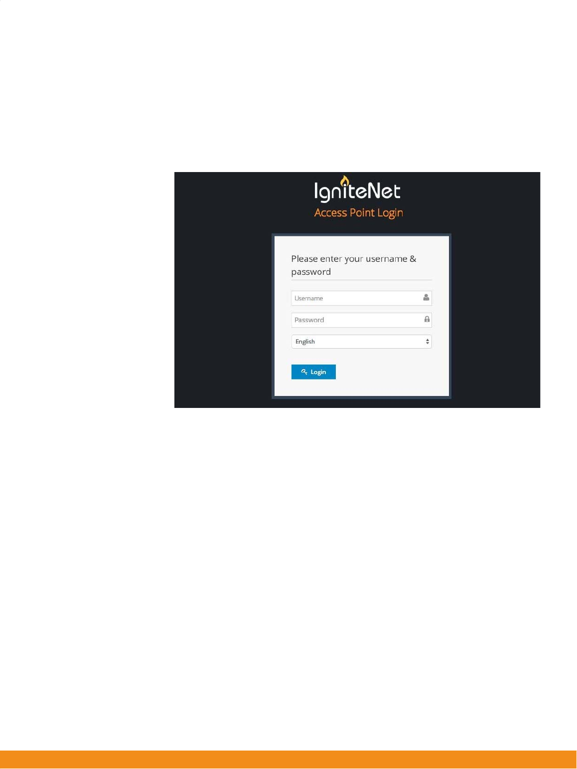
Logintotheinterfacebyenteringthedefaultusername“root”withthe
password“admin123”,thenclickLogin.
–
15
–
Chapter1
|
Introduction
ConnectingtotheWebInterface
Note:
Itisstronglyrecommendedtochangethedefaultusernameandpassword
thefirsttimeyouaccessthewebinterface.Forinformationonchanginguser
namesandpasswords,see“UserAccounts”onpage57.
Figure1:LoginPage
–
16
–
Chapter1
|
Introduction
SetupWizard
SetupWizard
TheSetupWizardisdesignedtohelpyouconfigurethebasicsettingsrequiredto
gettheAPupandrunning.
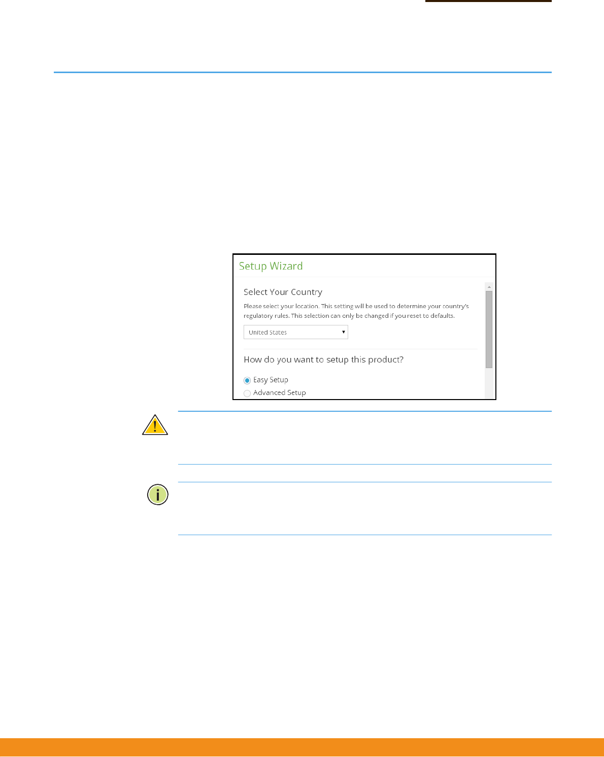
Step1 SelectYourCountry–Selecttheaccesspoint’scountryofoperationfromthedrop‐
downmenu.YoumustsettheAP’scountrycodetobesurethattheradiosoperate
accordingtopermittedlocalregulations.Thatis,settingthecountrycoderestricts
operationoftheAPtotheradiochannelsandtransmitpowerlevelspermittedfor
wirelessnetworksinthespecifiedcountry.
Figure2:SelectYourCountry
Caution:
Youmustsetthecountrycodetothecountryofoperation.Settingthe
countrycodeensuresthattheradiosoperatewithinthelocalregulationsspecified
forwirelessnetworks.
Note:Thecountrycodeselectionisfornon‐USmodelsonlyandisnotavailableto
allUSmodels.PerFCCregulation,allWi‐FiproductsmarketedintheUSmustbe
fixedtoUSoperationchannelsonly.
–
17
–
Chapter1
|
Introduction
SetupWizard
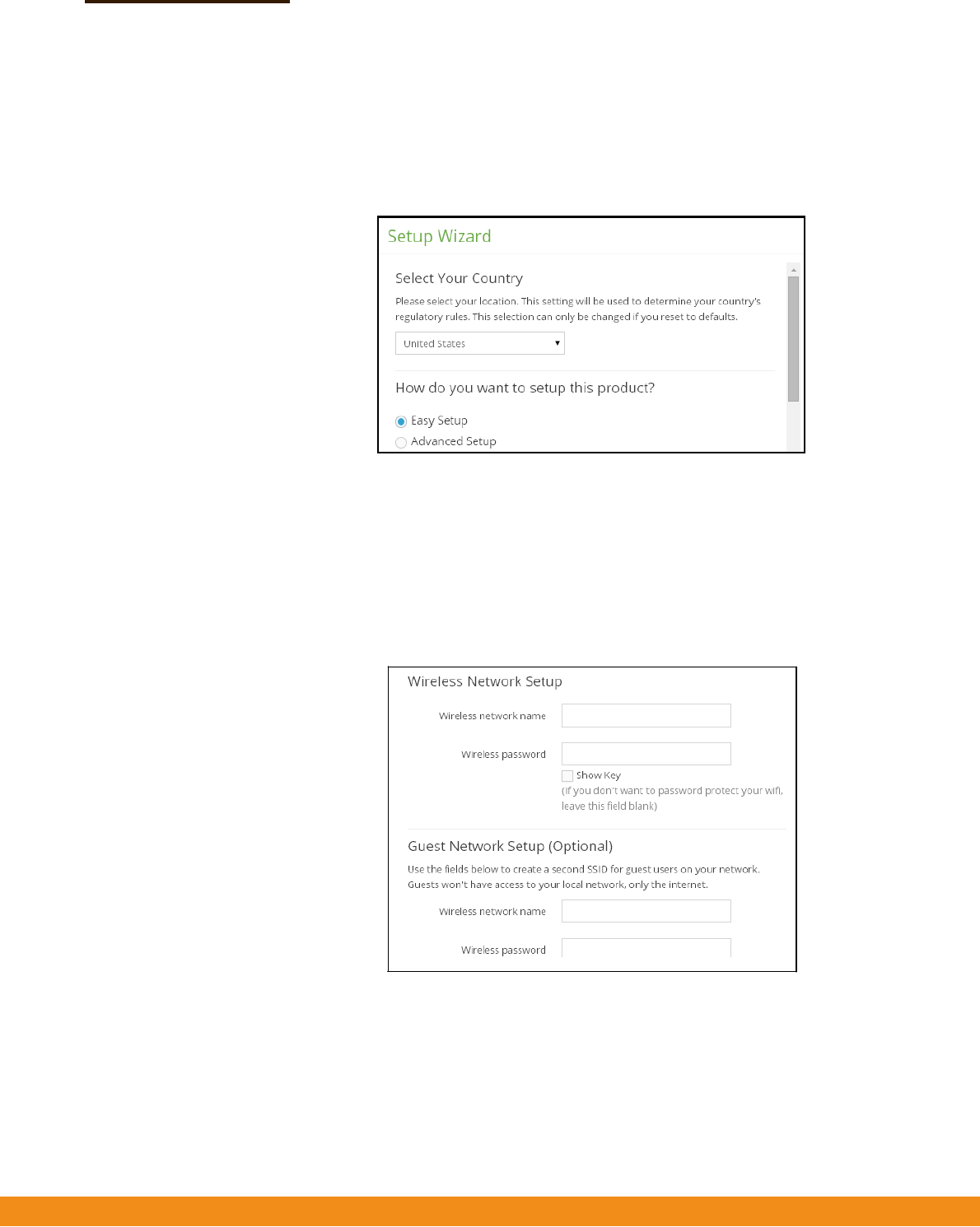
Step2 SelectSetupMethod–SelectEasySetuptosetbasicwirelessnetworkaccessand
guestnetworkaccessparameters,orAdvancedSetuptospecifynetworkingmodes
foranAPbridge,AProuter,ormanualconfiguration.
Figure3:SelectSetupMethod
Step3
ConfigureSettings
◆
EasySetup—Basicwirelessnetworkandguestnetworkaccessparameters.
Specifythenameandpasswordforthewirelessnetworkandguestnetwork.
TheNetworkingModeissettoAPRouterasdescribedunderAdvancedSetup.
Figure4:EasySetup
■
WirelessNetworkSetup—Setthenameandpasswordfortheprimary
wirelessnetwork.Apasswordmustbespecifiedtoprotectthenetwork
fromunauthorizedaccess.
–
18
–
Chapter1
|
Introduction
SetupWizard
■
GuestNetworkSetup—Setthenameandpasswordfortheguestwireless
network.ThiscreatesasecondSSIDforguestusers,limitingtheiraccess
onlytotheInternet.
◆
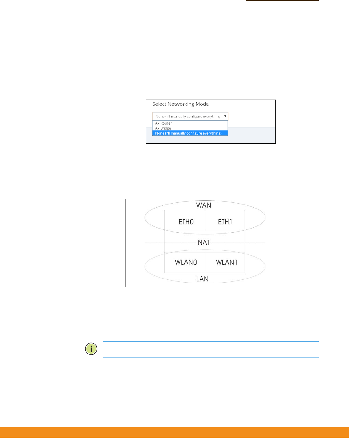
AdvancedSetup—NetworkingmodesforAPBridge,APRouter,ormanual
configuration.
Figure5:AdvancedSetup
■
APBridgeMode—ConfiguresaninterfaceasattachedtotheWAN(thatis,
theInternet).Inthefollowingfigure,EthernetPort0andEthernetPort1are
bothattachedtotheWAN.Trafficfromtheseinterfacesisdirectlybridged
intotheInternet.(ThisisalsocalledbridgetoInternet.)
Figure6:BridgetoInternet
■
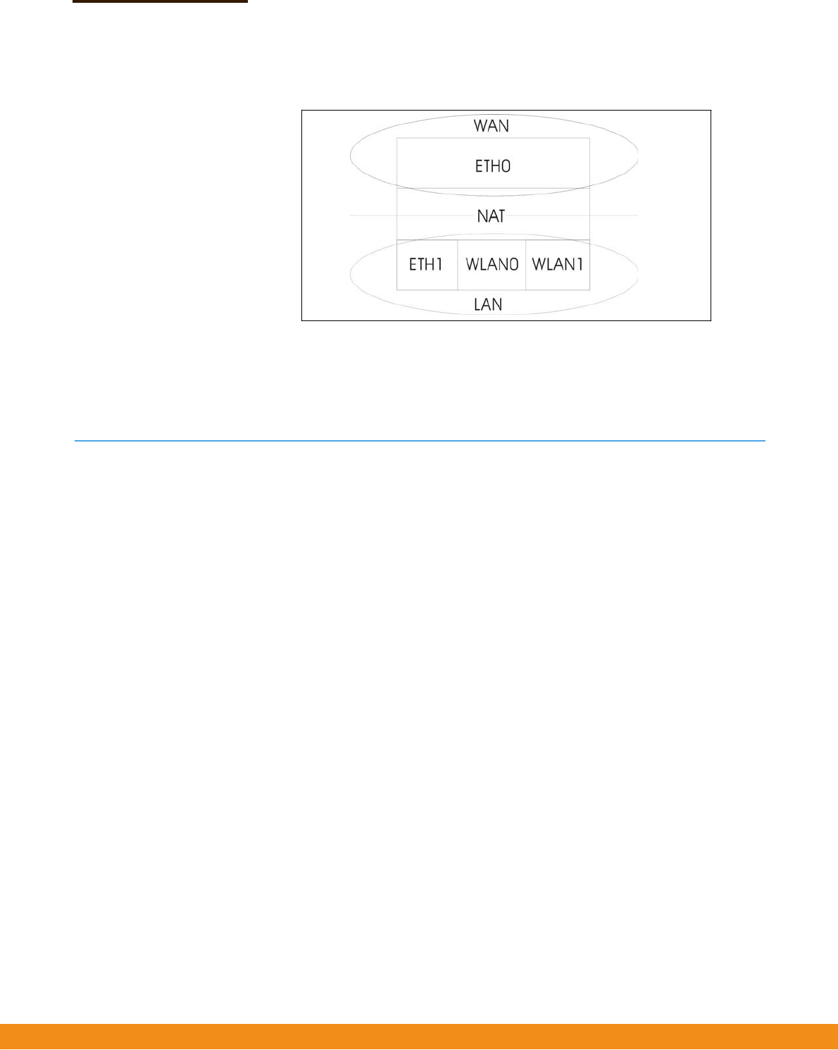
APRouterMode—ConfiguresaninterfaceasamemberoftheLAN.Inthe
followingfigure,EthernetPort1,WirelessLAN0(5GHzRadio),andWireless
LAN1(2.4GHzRadio)areallincludedintheLAN.Trafficfromthese
interfacesisroutedacrosstheaccesspointthroughEthernetPort0tothe
Internet.(ThisisalsocalledroutetoInternet.)
Note:
Single‐bandaccesspointsonlysupportoneWLAN.
–
19
–
Chapter1
|
Introduction
MainMenu
Figure7:RoutetoInternet
■
ManualMode—Allowsallconfigurationparameterstobemanually
configured.Anywiredmoduleorradiomodulemaybelogicallyplacedon
theWANandLANsideoftheaccesspoint.
MainMenu
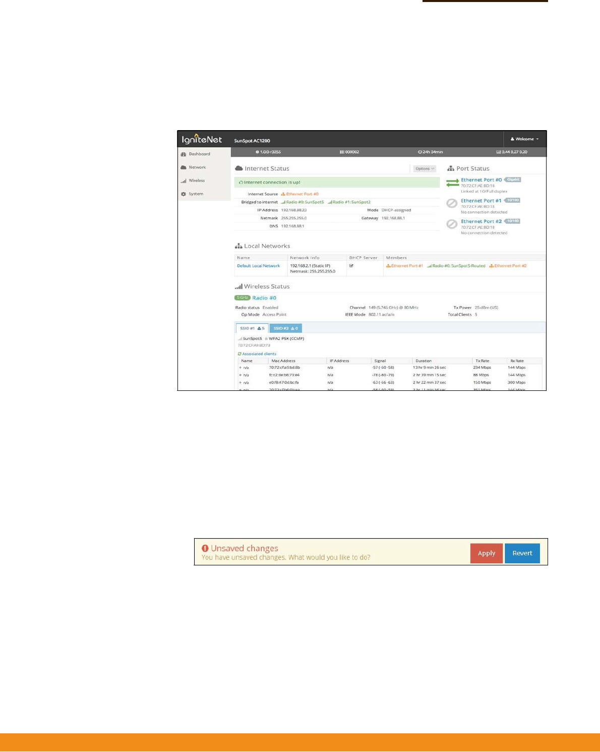
ThewebinterfaceMainMenuprovidesaccesstoalltheconfigurationsettings
availablefortheAP.
Toconfiguresettings,clicktherelevantMainMenuitem.EachMainMenuitemis
summarizedbelowwithlinkstotherelevantsectioninthisguidewherethe
configurationparametersaredescribedindetail:
◆
Dashboard—ThedashboardshowsbasicsettingsfortheAP,including
Internetstatus,localnetworksettings,wirelessradiostatus,andtrafficgraphs.
See“StatusInformation”onpage22.
◆
Network
—ConfiguresInternet,Ethernet,LAN,andHotspotsettings.See
“NetworkSettings”onpage28.
◆
Wireless
—Configures5GHzRadio,2.4GHzRadio,andVLANsettings.See
“WirelessSettings”onpage37
◆
System
—ConfiguresSystem(designationandlocation),Maintenance(suchas
viewlog,firmwareupgrade,andreset),UserAccounts,andServices
(managementaccessmethods).
–
20
–
Chapter1
|
Introduction
MainMenu
Dashboard Afterloggingintothewebinterface,thedashboarddisplays.Thedashboardshows
basicsettingsfortheAP,includingInternetstatus,localnetworksettings,wireless
radiostatus,andtrafficgraphs.
Figure8:TheDashboard
CommonWebPage
Buttons
Thelistbelowdescribesthecommonbuttonsfoundonmostoftheweb
managementpages:
◆
Save
–AppliesthenewparametersandsavesthemtotemporaryRAM
memory.Alsodisplaysamessageatthetopofthescreentoinformyouthatthe
changeshavenotyetbeensavedtoFlashmemory.Therunningconfiguration
will
not
besaveduponarebootunlessyouclickthe“Apply”button.
Figure9:SetConfigurationChanges
◆
Apply
–Savesthecurrentconfigurationsothatitisretainedafterarestart.
◆
Revert–Cancelsthenewlyenteredsettingsandrestorestheoriginals.
◆
Welcome>Logout
–OpentheWelcomelistandclickLogouttoendtheweb
managementsession.
◆
Welcome>ViewUsers
–OpentheWelcomelistandclickViewUserstoopen
theUserAccountsmenu.

–
20
–
Chapter1
|
Introduction
MainMenu

–
21
–
WebConfiguration
Thissectionprovidesdetailsonconfiguringtheaccesspointusingtheweb
browserinterface.
Thissectionincludesthesechapters:
◆
“StatusInformation”onpage22
◆
“NetworkSettings”onpage28
◆
“WirelessSettings”onpage37
◆
“SystemSettings”onpage52
SectionII

–
22
–
StatusInformation
TheDashboarddisplaysinformationonthecurrentsystemconfiguration,including
Internetstatus,localnetworksettings,wirelessradiostatus,andtrafficgraphs.
StatusInformationincludesthefollowingsections:
◆
“SystemandProductInformation”onpage22
◆
“InternetStatus”onpage22
◆
“LocalNetworks”onpage24
◆
“WirelessStatus”onpage25
◆
“TrafficGraphs”onpage27
SystemandProductInformation
TheSystemandProductInfosectionshowsdescriptiveinformationabouttheAP.
Figure10:SystemandProductInformation
Thefollowingitemsaredisplayedinthissection:
◆
Themodelnameoftheunit.
◆
Thesoftwareversionnumber.
◆
Theserialnumberofthephysicalaccesspoint.
◆
Lengthoftimethemanagementagenthasbeenup.
◆
Thelast1‐minute,5‐minuteand15‐minuteCPUloadaverage.
InternetStatus
TheInternetStatussectionshowsinformationabouttheInternetconnection.
2

–
23
–
Chapter2
|
StatusInformation
InternetStatus
Figure11:InternetStatus
Thefollowingitemsaredisplayedinthissection:
◆
InternetSource
—TheEthernetportconnectedtotheInternet.Bydefault,
thisisEthernetPort0.
◆
PortsbridgedtoInternet—Additionalinterfacesattacheddirectlytothe
Internet.(SeeConfigureSettings–“Step3”onpage16foramoredetailed
description.)
◆
IPAddress
—IPaddressoftheInternetconnection.
◆
Gateway—IPaddressofthegatewayrouterusedtopasstrafficbetweenthis
deviceandothernetworksegments.
◆
DNS—TheIPaddressoftheDomainNameServeronthenetwork.ADNS
mapsnumericalIPaddressestodomainnamesandcanbeusedtoidentify
networkhostsbyfamiliarnamesinsteadoftheIPaddresses.
◆
HotspotStatus
—Showsifthehotspotisenabledordisabled,andtheports
onwhichthisserviceisenabled.
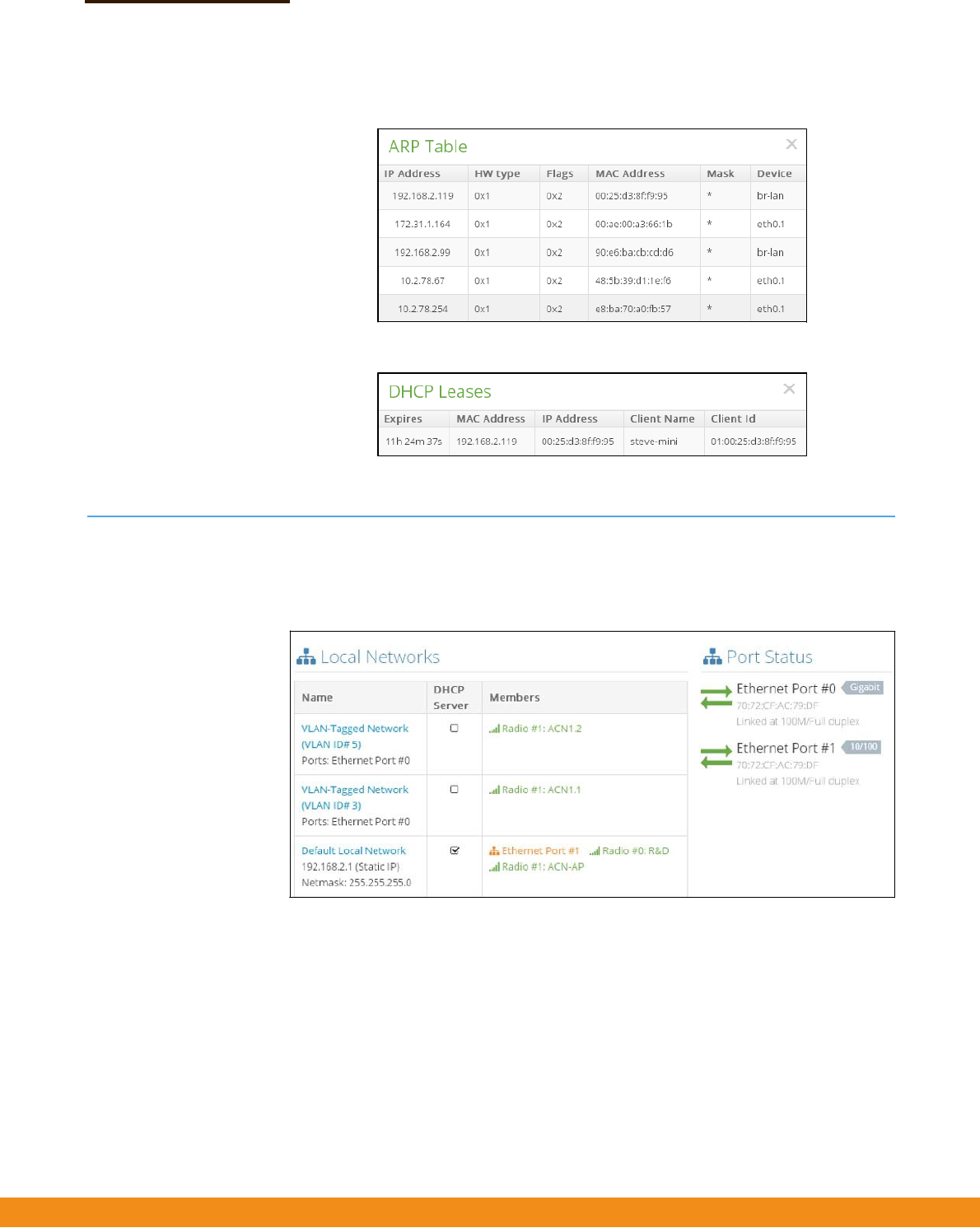
◆
Options
—IncludesshowingtheARPcache,showingDHCPleases,or
renewingDHCPleases.
Figure12:Options
–
24
–
Chapter2
|
StatusInformation
LocalNetworks
Figure13:ARPTable
Figure14:DHCPLeases
LocalNetworks
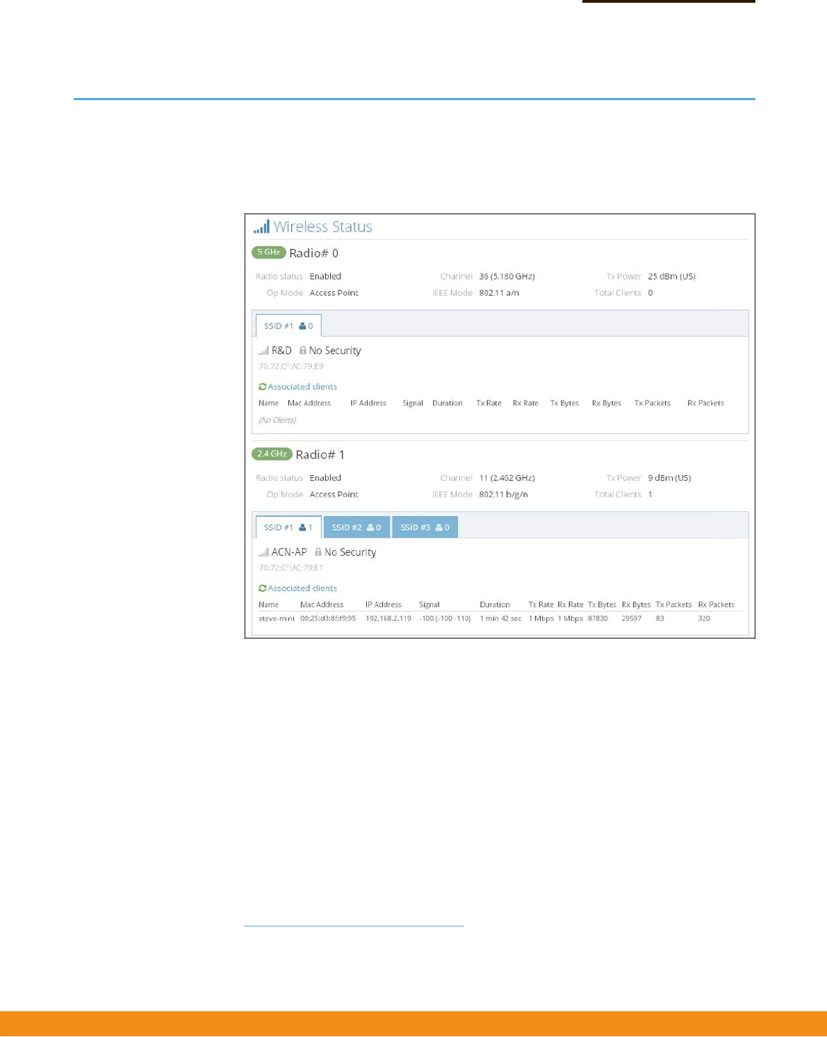
TheLocalNetworkssectionshowsinformationaboutthelocalnetworkconnection.
Figure15:LocalNetworks
Thefollowingitemsaredisplayedinthissection:
◆
Name
—Showsinformationonthenameofthelocalnetwork,whetherstatic
ordynamicconfigurationisused,andthenetworkmask.
◆
DHCPServer
—ShowsifDHCPserviceisenabledonthisnetwork.
◆
Members—Showstheportsandwirelessradiosattachedtothisnetwork.
◆
PortStatus
—ShowsthestatusoftheEthernetports,includinglinkupstate,
MACaddress,speed,andduplexmode.
–
25
–
Chapter2
|
StatusInformation
WirelessStatus
WirelessStatus
TheWirelessStatussectionshowsinformationabouttheradiosettingsand
associatedclients.
Figure16:WirelessStatus
Thefollowingitemsaredisplayedinthissection:
◆
Radio#
—Indicatesthe5GHzor2.4GHzwirelessinterface.
■
RadioStatus—Showsifthewirelessinterfaceisenabledordisabled.
■
OpMode—Showsiftheunitisconfiguredtooperateasanaccesspoint
(manuallyconfigured),anAPinbridgemode,oranAPinroutermode.
■
Channel—Theradiochanneltheaccesspointusestocommunicatewith
wirelessclients.Theavailablechannelsdependonthe802.11Mode
1
,
ChannelBandwidth
1
,andCountryCodesettings
2
.
■
IEEEMode—The802.11wirelessLANstandardssupportedbytheaccess
point.
1.
See“RadioSettings”onpage37.
2.
See“SetupWizard”onpage15.

–
26
–
Chapter2
|
StatusInformation
WirelessStatus
■
TxPower—Thepoweroftheradiosignalstransmittedfromtheaccess
point.
■
TotalClients—Thetotalnumberofclientsattachedtothisinterface.
◆
SSID#—Servicesetidentifier.Clientsthatwanttoconnecttothewireless
networkthroughanaccesspointmustsettheirSSIDstothesameasthatofthe
accesspoint.
■
NetworkName—Auniqueidentifierforthelocalwirelessnetwork.
■
Security—Showswhetherornotsecurityhasbeenenabled.
■
Associatedclients—Showsdetailedinformationaboutclients.
■
Name—Clientname.
■
MACAddress—TheMACaddressofthewirelessclient.
■
IPAddress—TheIPaddressassignedtothewirelessclient.
■
Signal—Signalstrength(TX/RX)indBm.
■
Duration—Thetimethewirelessclienthasbeenassociated.
■
TxRate—Thedatatransmitratetothewirelessclient.
■
RxRate—Thedatareceiveratefromthewirelessclient.
■
TxBytes—Thenumberoftransmittedbytestothisclient.
■
RxBytes—Thenumberofreceivedbytesfromthisclient
■
TxPackets—Thenumberoftransmittedpacketstothisclient.
■
RxPackets—Thenumberofreceivedpacketsfromthisclient.
–
27
–
Chapter2
|
StatusInformation
TrafficGraphs
TrafficGraphs
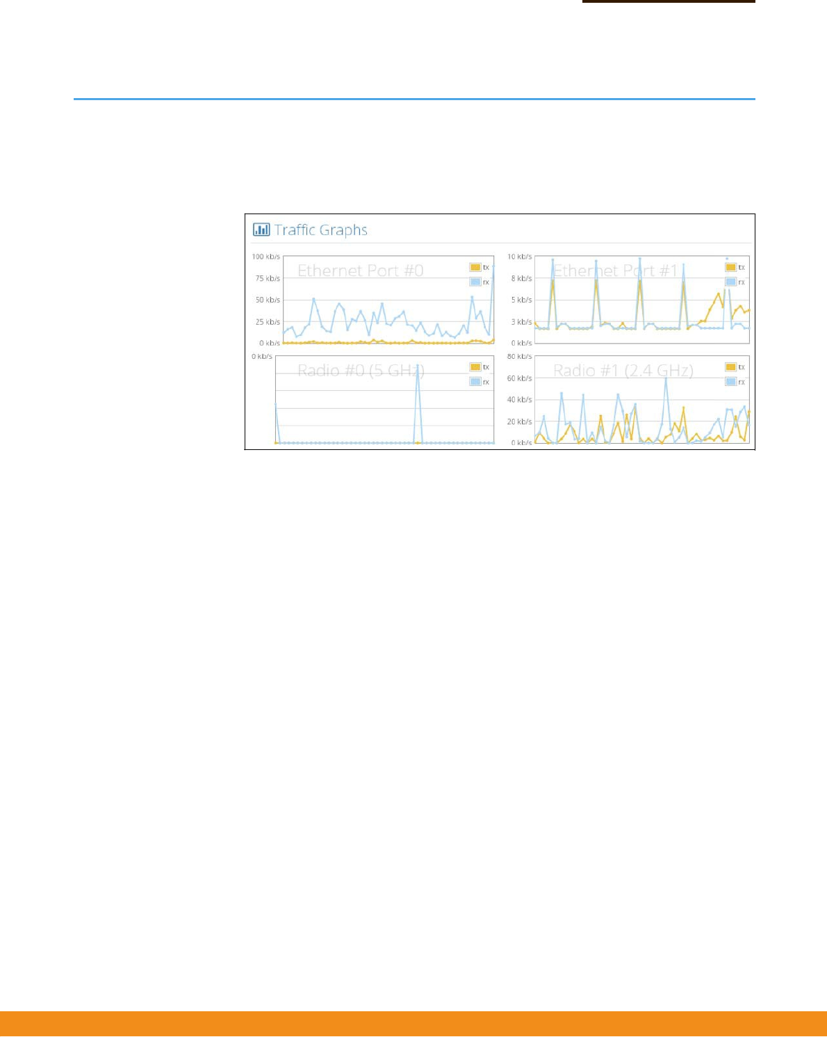
TheTrafficGraphssectionshowsthedataratefortheEthernetportsandwireless
interfaces.
Figure17:TrafficGraphs
–
28
–
NetworkSettings
Thischapterdescribesbasicnetworksettingsontheaccesspoint.Itincludesthe
followingsections:
◆
“InternetSettings”onpage28
◆
“EthernetSettings”onpage31
◆
“LANSettings”onpage33
◆
“HotspotSettings”onpage34
InternetSettings
TheInternetSettingspageconfiguresthebasicInternetsettingsfortheAP,suchas
thesourceport,IPaliases,aswellasthehostnameandmaximumMTUsize.
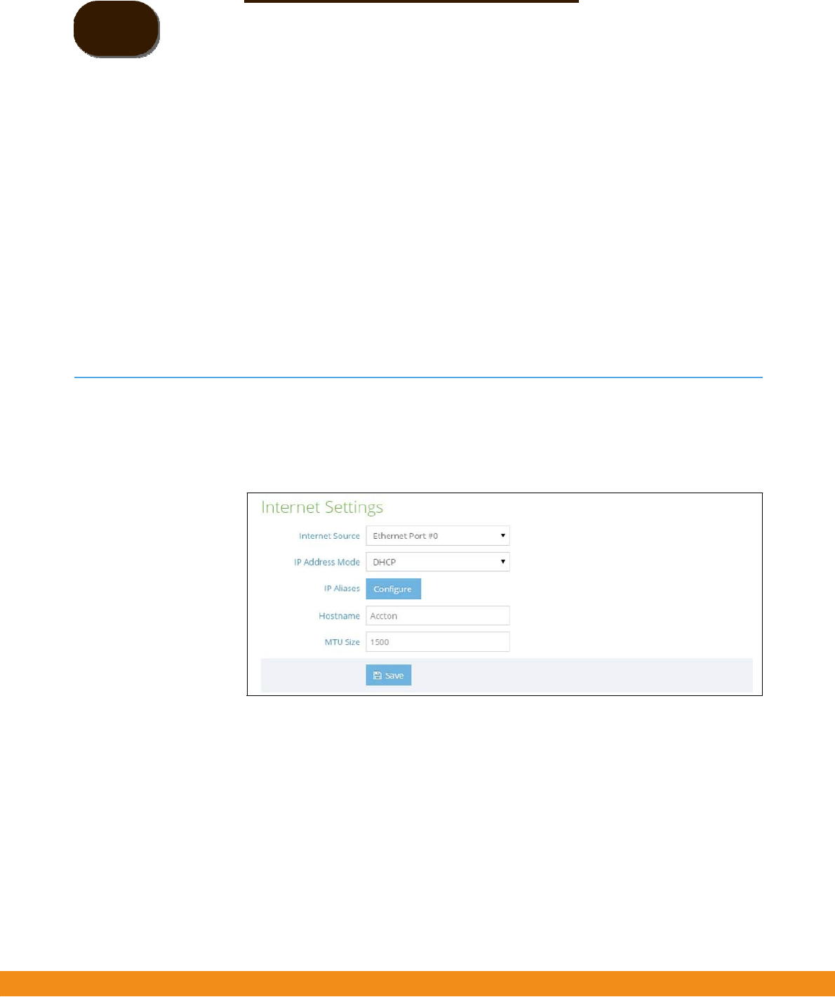
Figure18:InternetSettings
Thefollowingitemsaredisplayedonthispage:
◆
InternetSource—TheEthernetportusedtoaccesstheInternet.
(Default:EthernetPort0;Options:EthernetPort0‐1)
◆
IPAddressMode—ThemethodusedtoprovideanIPaddressfortheInternet
accessport.(Default:DHCP;Options:DHCP,staticIP,PPPoE)
■
DHCP
—ConfigurationoptionsdisplayedforDHCPareshowninFigure18,
“InternetSettings",onpage28.
3
–
29
–
Chapter3
|
NetworkSettings
InternetSettings
■
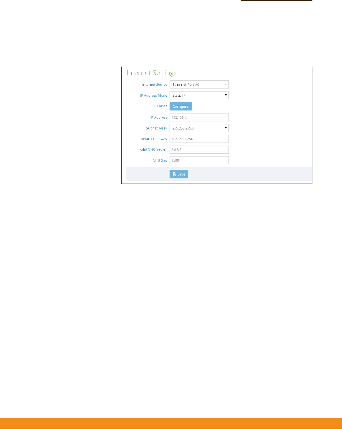
StaticIP—ToconfigureastaticIPaddressfortheselectedEthernet
interface,thefollowingitemsmustbespecified.
Figure19:IPAddressMode–StaticIP
■
IPAddress—SpecifiesanIPaddressfortheaccesspoint.ValidIP
addressesconsistoffourdecimalnumbers,0to255,separatedby
periods.(Default:192.168.1)
■
SubnetMask—Indicatesthelocalsubnetmask.
(Default:255.255.255.0)
■
DefaultGateway—TheIPaddressofthedefaultgateway,whichis
usediftherequesteddestinationaddressisnotonthelocalsubnet.
Ifyouhavemanagementstations,DNS,RADIUS,orothernetwork
serverslocatedonanothersubnet,typetheIPaddressofthedefault
gatewayrouterinthetextfieldprovided.
■
AddlDNSServer—TheIPaddressofDomainNameServersonthe
network.ADNSmapsnumericalIPaddressestodomainnamesand
canbeusedtoidentifynetworkhostsbyfamiliarnamesinsteadofthe
IPaddresses.
IfyouhaveaDNSserverslocatedonthelocalnetwork,typetheIP
addressinthetextfieldsprovided.
–
30
–
Chapter3
|
NetworkSettings
InternetSettings
■
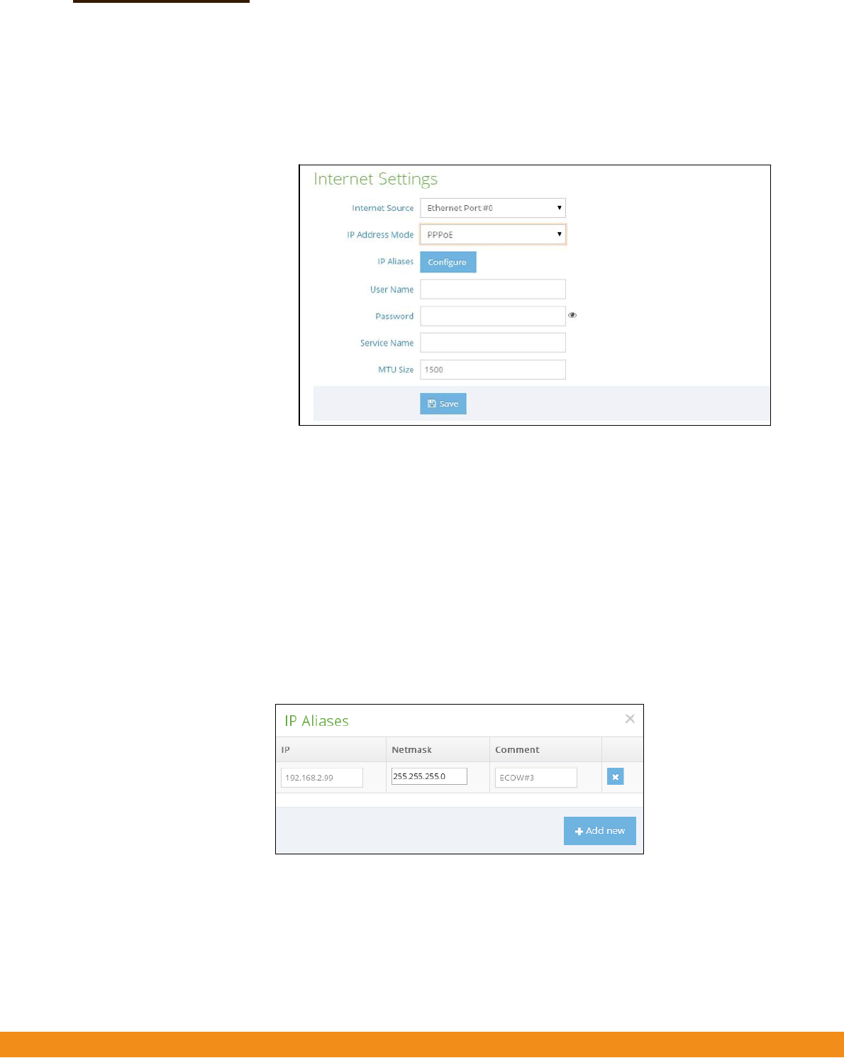
PPPoE—ToobtainanIPaddressfortheselectedEthernetinterfaceusing
PPPoE,thefollowingitemsmustbespecified.
Figure20:IPAddressMode–PPPoE
■
UserName—Theusernamespecifiedbytheserviceprovider.
(Range:1‐32characters)
■
Password—Thepasswordspecifiedbytheserviceprovider.
(Range:1‐32characters)
■
ServiceName
—TheservicenameassignedforthePPPoEconnection.
Theservicenameisnormallyoptional,butmayberequiredbysome
serviceproviders.(Range:1‐32alphanumericcharacters)
◆
IPAliases—AddsastaticIPv4addressunderwhichtheaccesspointcanalso
bereached.
Figure21:IPAlias
◆
MTUSize—Setsthesizeofthemaximumtransmissionunit(MTU)forpackets
sentonthisinterface.(Range:1400‐1500bytes;Default1500bytes)
–
31
–
Chapter3
|
NetworkSettings
EthernetSettings
EthernetSettings
TheEthernetSettingspageconfiguresthenetworkbehavioroftheEthernetports,
indicatingthataportprovidesanInternetconnectionforwirelessclientsattached
tothelocalnetwork(routedtotheInternet),isbridgeddirectlytotheInternet,
connectedtotheguestnetwork,orprovideshotspotservice.
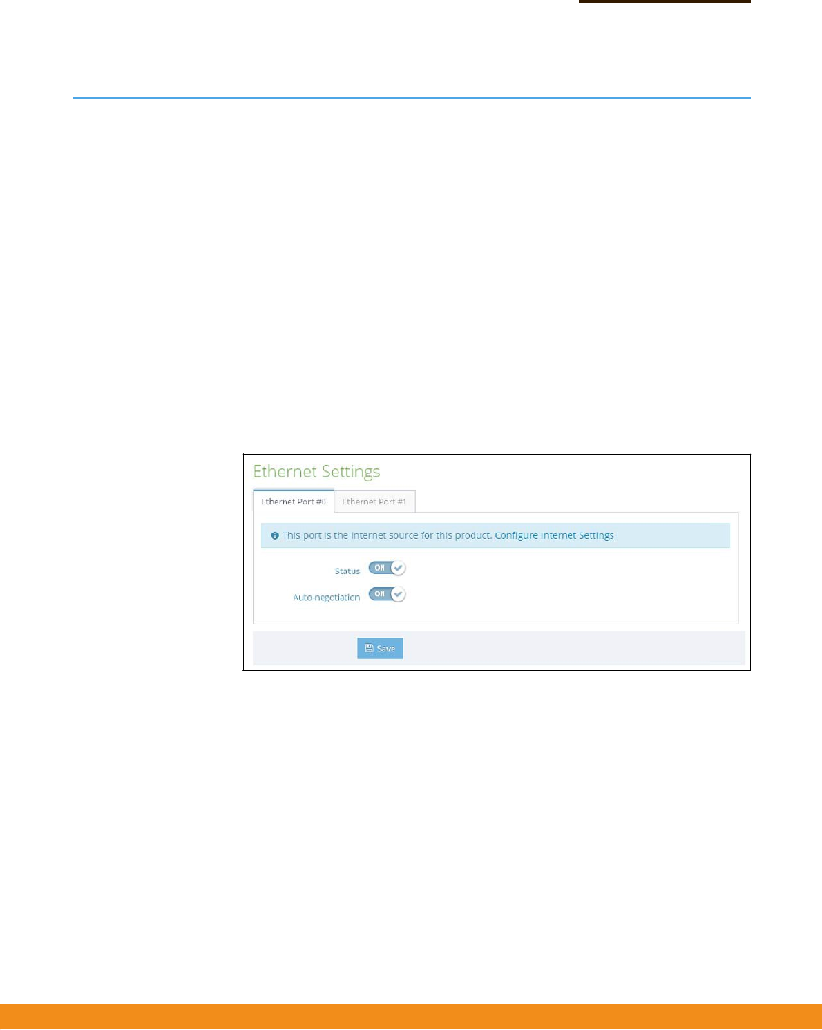
ThefollowingitemsarecommonforallpagesunderEthernetSettings:
◆
Status
—Enablesordisablesthisport.(Default:ON)
◆
Auto‐negotiation—Enablesordisablesauto‐negotiationforagiven
interface.(Default:ON)
1000BASE‐Tdoesnotsupportforcedmode.Auto‐negotiationshouldalwaysbe
usedtoestablishaconnectionoverany1000BASE‐Tport.
Whenauto‐negotiationisenabled,theaccesspointwillnegotiatethebest
settingsforalinkbasedonadvertisedcapabilities.
Figure22:EthernetSettings–InternetSource
Thefollowingstatusmessageisdisplayedifaninterfaceisconnectedtothe
Internet:
◆
“Thisportistheinternetsourceforthisproduct.ConfigureInternetSettings”
IfmorethanoneinterfaceisconnectedtotheInternet,onlythelastconfigured
interfaceisused.

–
32
–
Chapter3
|
NetworkSettings
EthernetSettings
Figure23:EthernetSettings–NetworkBehavior
Thefollowingitemsaredisplayedonthispage:
◆
NetworkBehavior
—FortheEthernetportwhichisnotprovidingInternet
access,oneofthefollowingconnectionmethodsmustbespecified.
(Default:RoutetoInternet)
■
BridgetoInternet
—ConfiguresaninterfacetobeattachedtotheWAN.
TrafficfromthisinterfaceisdirectlybridgedintotheInternet.(SeeFigure6,
“BridgetoInternet",onpage17.)IfanEthernetportisbridgedtothe
Internet,managementaccesscannotbemadebyadirectconnectionto
thisport.However,ifanotherEthernetportorradiointerfaceiswithinthe
LAN(routedtotheInternet)theaccesspointcanbemanagedthroughthis
interfacebyaPCwhichisconfiguredwithIPaddressinthesamesubnet.
■
RoutetoInternet
—ConfiguresaninterfacetobeamemberoftheLAN.
Trafficfromthisinterfaceisroutedacrosstheaccesspointandoutthrough
aninterfacewhichisbridgedtotheInternet.(SeeFigure7,“Routeto
Internet",onpage18.)Bydefault,EthernetPort1isroutedtoInternet,
allowingmanagementaccessviaadirectconnectiontoaPCconfigured
withanaddressinthesamesubnet.
■
NetworkName
—Thenetworktoberouted.Thedefaultis“Default
localnetwork”asdisplayedunderLANSettings–LocalNetworks.
■
AddtoGuestNetwork
—Thisportcanonlyaccesstheguestnetwork.
■
HotspotControlled
—Thisportcanonlyaccesshotspotservices.
■
ConfigureHotspot
—OpenstheHotspotSettingspage.
–
33
–
Chapter3
|
NetworkSettings
LANSettings
LANSettings
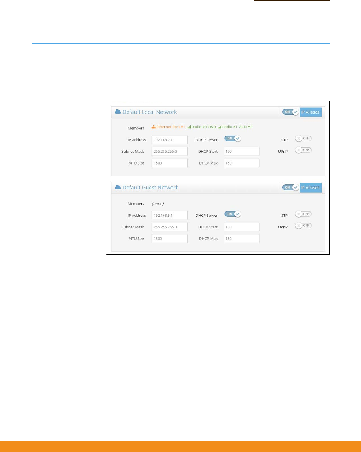
TheLANSettingspageconfigurestheLANsettingsforthelocalnetworkandguest
network,includingIPinterfacesetting,DHCPserversettings,STPadministrative
status,andUPnPadministrativestatus.
Figure24:Network–LANSettings
Thefollowingitemsaredisplayedonthispage:
◆
Members—Theinterfacesattachedtothelocalareanetwork.
◆
IPAddress—SpecifiestheIPaddressforthelocalnetworkorguestnetwork.
ValidIPaddressesconsistoffourdecimalnumbers,0to255,separatedby
periods.(Default:192.168.2.1)
◆
SubnetMask—Indicatesthelocalsubnetmask.(Default:255.255.255.0)
◆
MTUSize—Setsthesizeofthemaximumtransmissionunit(MTU)forpackets
sentonthisnetwork.
◆
DHCPServer
—Enables/disablesDHCPonthisnetwork.(Default:Enabled)
■
DHCPStart—Firstaddressintheaddresspool.(Range:1‐256;
Default:x.x.x.100)
■
DHCPMax—Maximumnumberofaddressesintheaddresspool.
(Range:1‐255;Default:150)
–
34
–
Chapter3
|
NetworkSettings
HotspotSettings
◆
STP
—EnablesordisablesprocessingofSpanningTreeProtocolmessages.
(Default:Disabled)
◆
UPnP
—EnablesordisablesUniversalPlug‐and‐Playbroadcastmessages.
(Default:Disabled)
HotspotSettings
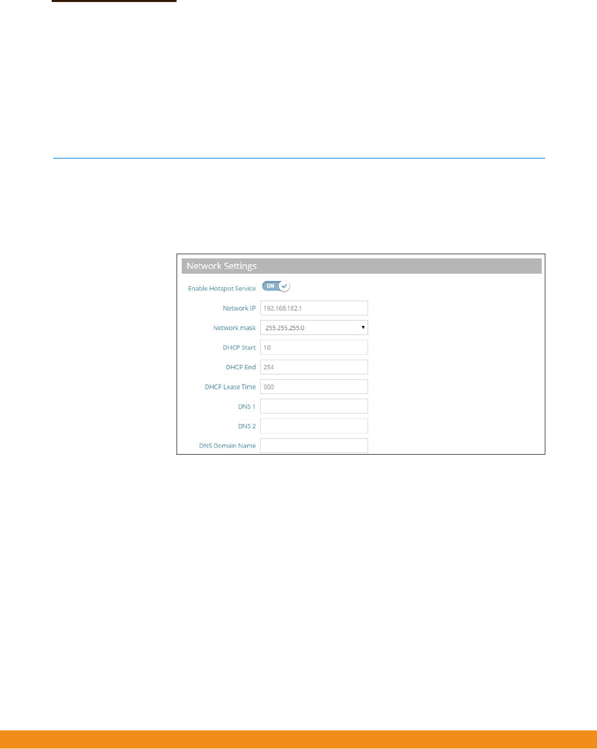
TheHotspotSettingspagecanconfigureInternetaccesstothegeneralpublicin
placessuchascoffeehouses,librariesandhospitals.Specificaccessrightsmayalso
bedefinedthroughaRADIUSserver.
Figure25:HotspotSettings(NetworkSettings)
Thefollowingitemsaredisplayedonthispage:
◆
NetworkIP—SpecifiestheIPaddressforthehotspot.ValidIPaddresses
consistoffourdecimalnumbers,0to255,separatedbyperiods.(Default:
192.168.182.1)
◆
NetworkMask—NetworkmaskfortheassociatedIPsubnet.Thismask
identifiesthehostaddressbitsusedforroutingtospecificsubnets.
◆
DHCPStart
—Startingnumberof(lastnumericfield)inaddresspool.
(Range:1‐254;Default:10)
◆
DHCPEnd—Endingnumberof(lastnumericfield)inaddresspool.
(Range:1‐254;Default:254)
◆
DHCPLeaseTime—ThedurationthatanIPaddressisassignedtoaDHCP
client.(Range:600‐43200seconds;Default:600seconds)
–
35
–
Chapter3
|
NetworkSettings
HotspotSettings
◆
DNS1—TheIPaddressoftheprimaryDomainNameServeronthenetwork.A
DNSmapsnumericalIPaddressestodomainnamesandcanbeusedtoidentify
networkhostsbyfamiliarnamesinsteadoftheIPaddresses.
◆
DNS2
—ThesecondaryDNSserveravailabletoDHCPclients.
◆
DNSDomainName
—Thedomainnameusedtoresolveincompletehost
namesviatheDomainNameSystem.(Range:1‐32characters)
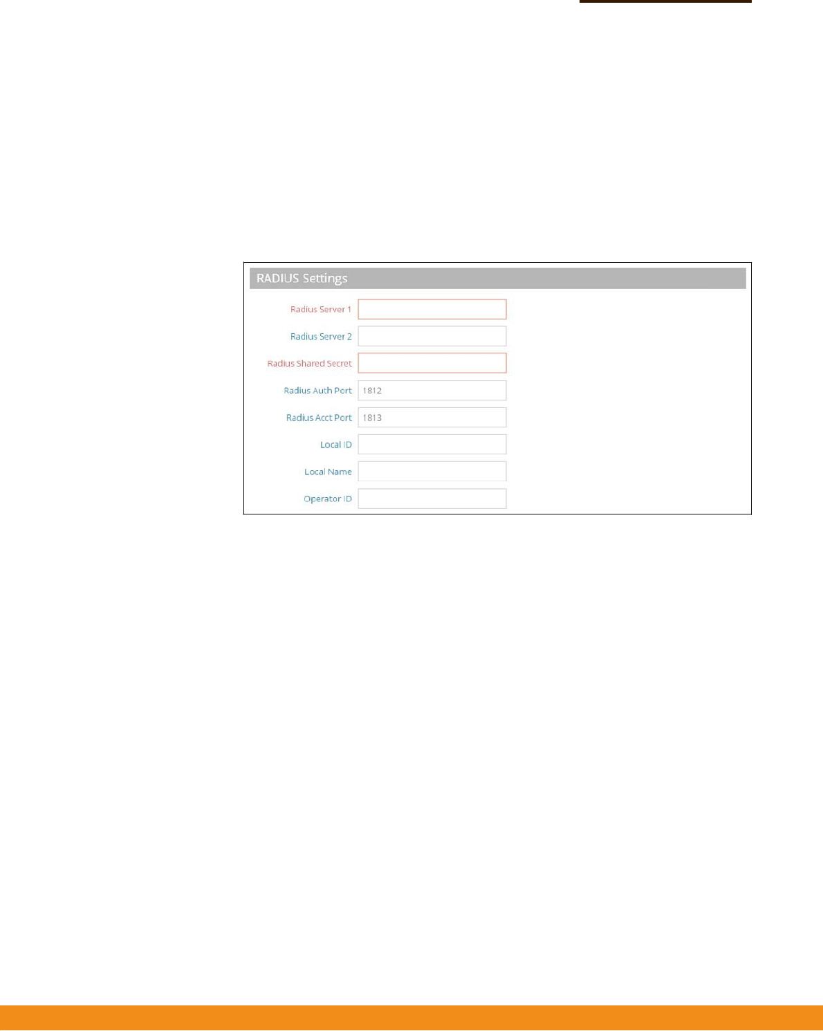
Figure26:HotspotSettings(RADIUSSettings)
Thefollowingitemsaredisplayedonthispage:
◆
RadiusServer1
—IPaddressorhostnameoftheprimaryRADIUSserver.
◆
RadiusServer2—IPaddressorhostnameofthesecondaryRADIUSserver.
◆
RadiusSharedSecret—Asharedtextstringusedtoencryptmessages
betweentheaccesspointandtheRADIUSserver.Besurethatthesametext
stringisspecifiedontheRADIUSserver.Donotuseblankspacesinthestring.
(Range:1‐255characters).
◆
RadiusAuthPort—RADIUSserverUDPportusedforauthentication
messages.(Range:1‐65535,Default:1812)
◆
RadiusAcctPort
—RADIUSserverUDPportusedforaccountingmessages.
(Range:1‐65535,Default:1813)
◆
LocalID
—LocalRADIUSserveridentifier.
◆
LocalName
—LocalRADIUSservername
◆
OperationID
—LocalRADIUSserveroperationidentifier.
–
36
–
Chapter3
|
NetworkSettings
HotspotSettings
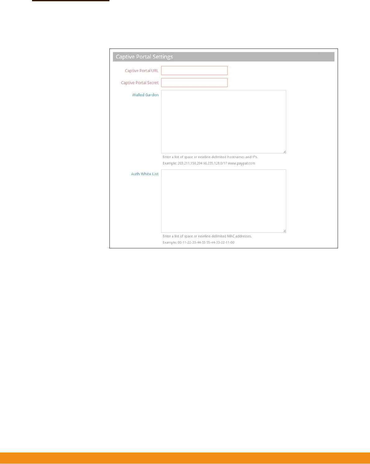
Figure27:HotspotSettings(CaptivePortalSettings)
Thefollowingitemsaredisplayedonthispage:
◆
CaptivePortalURL—HostnameofInternetserviceportalforthehotspot.
Thecaptiveportalforcesahotspotclienttoaccessawelcomewebpage(normally
usedforauthentication)beforegainingfurtheraccesstotheInternet.
The
welcomepagemayrequireauthenticationand/orpayment.
◆
CaptivePortalSecret
—Thepasswordusedforloggingintothehotspot.
◆
WalledGarden—Alistofwebsitestowhichunauthenticatedusersare
allowedtonavigate.
◆
AuthWhiteList—AlistofMACaddressesthatareallowedtobypassthe
captiveportaltoaccesstheinternet.

–
37
–
WirelessSettings
Thischapterdescribeswirelesssettingsontheaccesspoint.Itincludesthe
followingsections:
◆
“RadioSettings”onpage37
◆
“VLANSettings”onpage50
RadioSettings
TheIEEE802.11wirelessinterfacesincludeconfigurationoptionsforradiosignal
characteristicsandwirelesssecurityfeatures.
Theaccesspointcanoperateinseveralradiomodes,802.11a/a+n/AC(5GHz)or
802.11b+g/b+g+n(2.4GHz).Supportedmodesdependontheaccesspointmodel.
Notethatthedual‐bandaccesspointscanoperateat2.4GHzand5GHzatthe
sametime.Thewebinterfaceidentifiestheradioconfigurationpagesas:
◆
Radio0—the5GHz802.11a/n/ACradiointerface
◆
Radio1—the2.4GHz802.11b/g/nradiointerface
Eachradiosupports8virtualaccesspoint(VAP)interfacesbasedontheSSIDs,
referredtoasVAP0~VAP7.EachVAPfunctionsasaseparateaccesspoint,andcan
beconfiguredwithitsownServiceSetIdentification(SSID)andsecuritysettings.
However,mostradiosignalparametersapplytoallVAPinterfaces.Traffictospecific
VAPscanbesegregatedbasedonusergroupsorapplicationtraffic.Theclients
associatewitheachVAPinthesamewayastheywouldwithseparatephysical
accesspoints.TheAPsupportsuptoatotalof127wirelessclientsacrossallVAP
interfacesperradio.
4
–
38
–
Chapter4
|
WirelessSettings
RadioSettings
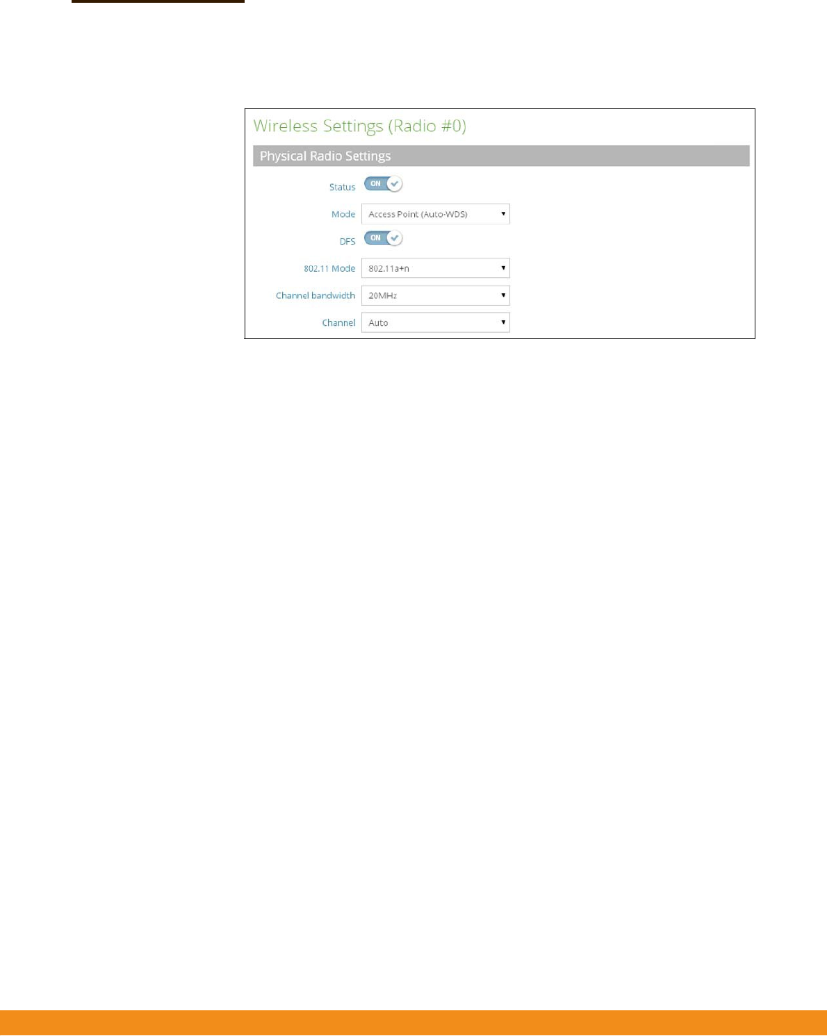
Figure28:RadioSettings(PhysicalRadioSettings)
Thefollowingitemsaredisplayedonthispage:
◆
Status
—Enablesordisablesthewirelessserviceonthisinterface.
◆
Mode—SelectsthemodeinwhichtheAPwillfunction.
■
AccessPoint(Auto‐WDS)
—TheVAPoperatesasanaccesspointinWDS
mode,whichacceptsconnectionsfromAPsinClientWDSmode.(Thisis
thedefaultsetting.)
Inthismode,theAPprovidesservicestoclientsasanormalaccesspoint.
WDSisusedtoautomaticallysearchforandconnecttootherAPnodes
usingthesameSSIDandsecuritysettings.
■
Client—TheAPcanprovideawirelessconnectiontoanotherAP.Inthis
mode,itcanpassinformationfromortolocallywiredhosts,butdoesnot
provideservicestoanywirelessclients.
■
ClientWDS—TheAPprovidesservicestoclientsasanormalaccesspoint,
andoperatesasaclientstationinWDSmode,whichcanconnecttoother
accesspointsinAuto‐WDSmode.ConnectiontoanotherAPcanbemade
automaticallybyotheraccesspointsoperatinginAuto‐WDSmode.
◆
DFS—DynamicFrequencySelectioncanbeusedtodetectandavoid
interferencewithRadarsystemsoperatinginthe5GHzrange(UNIIchannels
52‐64and100‐140).Ifradarisdetected,theAPwillalterthechannelitis
operatingonandtellassociatedstationsthechanneltowhichitismoving.This
allowsstationstore‐associatewithminimuminterruption.(Thisparameteris
onlyapplicabletothe5GHzradio,andisenabledbydefault.)
◆
802.11Mode
—Definestheradiooperationmode.
■
Radio0(5GHzRadio)—Default:11a+n;Options:11a,11a+n,11AC
■
Radio1
(2.4GHzRadio)—Default:11b+g;Options:11b+g,11b+g+n

–
39
–
Radio 0(5 GHz) Radio 1(2.4GHz)
Chapter4
|
WirelessSettings
RadioSettings
◆
ChannelBandwidth
—TheAPoptionsforchannelbandwidthinclude5,10,
20,40and80MHz.Using20MHzgivesan802.11gconnectionaspeedof
54Mbpsandan802.11nconnectionaspeedofupto108Mbps,andensures
backwardcomplianceforslower802.11bdevices.Settingthechannel
bandwidth
to40MHzprovidesaconnectionspeedfor802.11nofupto300Mbps.Usinga
channelbandwidthof80MHzprovidesaconnectionspeedupto
866.7Mbps.(Default:20MHz;Range:5MHz,10MHz,20MHz,40MHz,80MHz)
◆
Channel—Theradiochannelthattheaccesspointusestocommunicatewith
wirelessclients.Whenmultipleaccesspointsaredeployedinthesamearea,set
thechannelonneighboringaccesspointsatleastfivechannelsaparttoavoid
interferencewitheachother.Forexample,for11g/n20MHzmodeyoucan
deployuptothreeaccesspointsinthesameareausingchannels1,6,11.Note
thatwirelessclientsautomaticallysetthechanneltothesameasthatusedby
theaccesspointtowhichitislinked.(Theavailablechannelsaredependenton
the802.11Mode,ChannelBandwidth,andCountryCodesettings.)
SelectingAutoenablestheaccesspointtoautomaticallyselectanunoccupied
radiochannel.(Default:Auto)
Table1:RadioChannels
RadioChannels
a
Frequency(GHz)
RadioChannels Frequency(GHz)
Auto
Autoscan
Auto
Autoscan
365.18012.412
405.20022.417
445.22032.422
485.24042.427
1495.74552.432
1535.76562.437
1575.78572.422
1615.80582.447
1655.82592.452
102.457
112.462
a.Supportedchannelsdependonthe802.11modeandchannelbandwidth.
–
40
–
Chapter4
|
WirelessSettings
RadioSettings
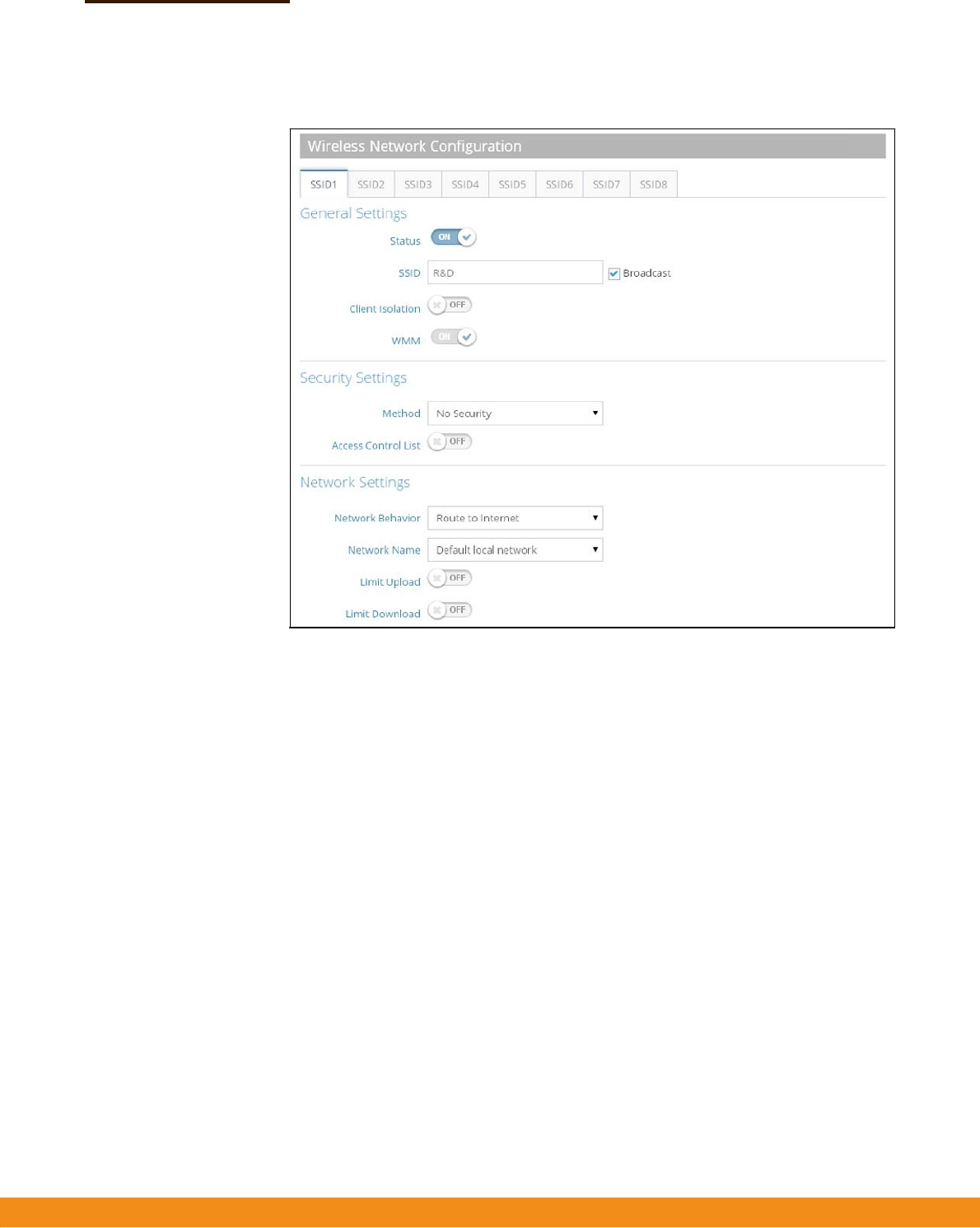
Figure29:RadioSettings(WirelessNetworkConfiguration)
Thefollowingitemsaredisplayedonthispage:
GeneralSettings
◆
Status
—EnablesordisablesthewirelessserviceonthisVAP.
◆
SSID—ThenameofthebasicservicesetprovidedbyaVirtualAccessPoint
(VAP)interface.Clientsthatwanttoconnecttothenetworkthroughtheaccess
pointmustsettheirSSIDtothesameasthatoftheaccesspoint’sVAPinterface.
(Default:ACN0.#(where#is0‐7)for5GHz,ACN1.#(where#is0‐7)for2.4GHz;
Range:1‐32characters)
◆
Broadcast
—TheSSIDcanbebroadcastatregularintervalssothatwireless
stationssearchingforanetworkconnectioncandiscoverit.Thisallowswireless
clientstodynamicallydiscoverandroambetweenWLANs.Thisfeaturealso
makesiteasierforhackerstobreakintoyourhomenetwork.BecauseSSIDsare
notencrypted,itiseasytograbonebysnoopingtheWLANlookingforSSID
broadcastmessagescomingfromtheAP.(Default:Enabled)
◆
ClientIsolation
—Ifenabled,wirelessclientscantalktotheLAN,andreach
theInternetifsuchconnectionisavailable,buttheycannotcommunicatewith
oneanother.(DefaultDisabled)

–
41
–
Chapter4
|
WirelessSettings
RadioSettings
◆
WMM—SetstheWMMoperationalmodeontheaccesspoint.Whenenabled,
theparametersforeachAccessCategory(AC)queuewillbeemployedonthe
accesspointandQoScapabilitiesadvertisedtoWMM‐enabledclients.
(Default:
Enabled)
Whenenabled,WMMmustbesupportedonanydevicetryingtoassociated
with
theaccesspoint.Devicesthatdonotsupportthisfeaturewillnotbe
allowedto
associatewiththeaccesspoint.
Wirelessnetworksofferanequalopportunityforalldevicestotransmitdata
fromanytypeofapplication.Althoughthisisacceptableformostapplications,
multimediaapplications(withaudioandvideodata)areparticularlysensitive
tothedelayandthroughputvariationsthatresultfromthis“equalopportunity”
wirelessaccessmethod.Formultimediaapplicationstorunwelloverawireless
network,aQualityofService(QoS)mechanismisrequiredtoprioritizetraffic
typesandprovidean“enhancedopportunity”wirelessaccessmethod.
TheaccesspointimplementsQoSusingtheWi‐FiMultimedia(WMM)standard.
UsingWMM,theaccesspointisabletoprioritizetrafficandoptimize
performancewhenmultipleapplicationscompeteforwirelessnetwork
bandwidthatthesametime.WMMemploystechniquesthatareasubsetofthe
IEEE802.11eQoSstandardanditenablestheaccesspointtointer‐operatewith
bothWMM‐enabledclientsandotherdevicesthatmaylackanyWMM
functionality.
AccessCategories—WMMdefinesfouraccesscategories(ACs):voice,video,
besteffort,andbackground.Thesecategoriescorrespondtotrafficpriority
levelsandaremappedtoIEEE802.1Dprioritytags(seeFigure2,“WMMAccess
Categories",onpage41).ThedirectmappingofthefourACsto802.1D
prioritiesisspecificallyintendedtofacilitateinteroperabilitywithotherwired
networkQoSpolicies.WhilethefourACsarespecifiedforspecifictypesof
traffic,WMMallowstheprioritylevelstobeconfiguredtomatchanynetwork‐
wideQoSpolicy.WMMalsospecifiesaprotocolthataccesspointscanuseto
communicatetheconfiguredtrafficprioritylevelstoQoS‐enabledwireless
clients.
Table2:WMMAccessCategories
AC_VO(AC3)VoiceHighestpriority,minimumdelay.Time‐sensitive
datasuchasVoIP(VoiceoverIP)calls.
AC_VI(AC2)VideoHighpriority,minimumdelay.Time‐sensitivedata
suchasstreamingvideo.
7,6
5,4
AC_BE(AC0)BestEffortNormalpriority,mediumdelayandthroughput.
Dataonlyaffectedbylongdelays.Datafrom
applicationsordevicesthatlackQoScapabilities.
AC_BK(AC1)
Background
Lowestpriority.Datawithnodelayorthroughput
requirements,suchasbulkdatatransfers.
0,3
2,1
Access
Category
WMM
Description
Designation
802.1D
Tags

–
42
–
Chapter4
|
WirelessSettings
RadioSettings
WMMOperation—WMMusestrafficprioritybasedonthefourACs;Voice,
Video,
BestEffort,andBackground.ThehighertheACpriority,thehighertheprobability
thatdataistransmitted.
Whentheaccesspointforwardstraffic,WMMaddsdatapacketstofour
independenttransmitqueues,oneforeachAC,dependingonthe802.1Dpriority
tagofthepacket.Datapacketswithoutaprioritytagarealwaysadded
totheBest
EffortACqueue.Fromthefourqueues,aninternal“virtual”collision
resolution
mechanismfirstselectsdatawiththehighestprioritytobegrantedatransmit
opportunity.Thenthesamecollisionresolutionmechanismisused
externallyto
determinewhichdevicehasaccesstothewirelessmedium.
ForeachACqueue,thecollisionresolutionmechanismisdependentontwo
timingparameters:
◆AIFSN(ArbitrationInter‐FrameSpaceNumber),anumberusedto
calculatetheminimumtimebetweendataframes
◆CW(ContentionWindow),anumberusedtocalculatearandombackofftime
Afteracollisiondetection,abackoffwaittimeiscalculated.Thetotalwaittimeis
thesumofaminimumwaittime(ArbitrationInter‐FrameSpace,orAIFS)
determinedfromtheAIFSN,andarandombackofftimecalculatedfromavalue
selectedfromzerototheCW.TheCWvaluevarieswithinaconfigurablerange.
It
startsatCWMinanddoublesaftereverycollisionuptoamaximumvalue,
CWMax.
Afterasuccessfultransmission,theCWvalueisresettoitsCWMin
value.
Figure30:WMMBackoffWaitTimes
Forhigh‐prioritytraffic,theAIFSNandCWvaluesaresmaller.Thesmallervalues
equatetolessbackoffandwaittime,andthereforemoretransmit
opportunities.
High Priority
Low Priority
Time
CWMin CWMax
A
IFS
Random Backof
f
Minimum Wait Time Random Wait Time
CWMin CWMax
A
IFS
Random Backof
f
Minimum Wait Time Random Wait Time

–
43
–
Chapter4
|
WirelessSettings
RadioSettings
SecuritySettings
◆
Method—SetsthewirelesssecuritymethodforeachVAP,including
associationmode,encryption,andauthentication.(Default:NoSecurity)
■
NoSecurity—TheVAPbroadcastsabeaconsignalincludingthe
configuredSSID.WirelessclientswithanSSIDsettingof“any”canreadthe
SSIDfromthebeaconandautomaticallysettheirSSIDtoallowimmediate
connection.
■
WEPOpenSystem—TheVAPbroadcastsabeaconsignalincludingthe
configuredSSID.WirelessclientswithanSSIDsettingof“any”canreadthe
SSIDfromthebeaconandautomaticallysettheirSSIDtoallowimmediate
connection.
■
Key—WEPisusedtoencryptdatatransmittedbetweenwireless
clientsandtheVAP.WEPusesstaticsharedkeys(fixed‐length
hexadecimaloralphanumericstrings)thataremanuallydistributedto
allclientsthatwanttousethenetwork.
WEPisthesecurityprotocolinitiallyspecifiedintheIEEE802.11
standardforwirelesscommunications.Unfortunately,WEPhasbeen
foundtobeseriouslyflawedandcannotberecommendedforahigh
levelofnetworksecurity.Formorerobustwirelesssecurity,theaccess
pointprovidesWi‐FiProtectedAccess(WPA)andWPA2forimproved
dataencryptionanduserauthentication.
BesurethattheWEPsharedkeysarethesameforeachclientinthe
wirelessnetwork.Allclientssharethesamekeys,whichareusedfor
dataencryption.
For64‐bitWEP,stringlengthmustbe5ASCIIcharacters(lettersand
numbers)or10hexadecimaldigits.For128‐bitWEP,stringlengthmust
be13ASCIIcharacters(lettersandnumbers)or26hexadecimaldigits.
■
WPA‐PSK—Forenterprisedeployment,WPArequiresaRADIUS
authenticationservertobeconfiguredonthewirednetwork.However,for
smallofficenetworksthatmaynothavetheresourcestoconfigureand
maintainaRADIUSserver,WPAprovidesasimpleoperatingmodethatuses
justapre‐sharedpasswordfornetworkaccess.ThePre‐SharedKeymode
usesacommonpasswordforuserauthenticationthatismanuallyentered
ontheaccesspointandallwirelessclients.ThePSKmodeusesthesame
TKIPpacketencryptionandkeymanagementasWPAintheenterprise,
providingarobustandmanageablealternativeforsmallnetworks.
■
Encryption
—Dataencryptionusesoneofthefollowingmethods:
■
CCMP(AES)—AES‐CCMPisusedasthemulticastencryption
cipher.AES‐CCMPisthestandardencryptioncipherrequiredfor
WPA2.(Thisisthedefaultsetting.)
■
TKIP
—TKIPisusedasthemulticastencryptioncipher.

–
44
–
Chapter4
|
WirelessSettings
RadioSettings
■
Auto:TKIP+CCMP(AES)
—Theencryptionmethodusedbythe
clientisdiscoveredbytheaccesspoint.
■
Key—WPAisusedtoencryptdatatransmittedbetweenwireless
clientsandtheVAP.WPAusesstaticsharedkeys(fixed‐length
hexadecimaloralphanumericstrings)thataremanuallydistributedto
allclientsthatwanttousethenetwork.
Stringlengthmustbe8to63ASCIIcharacters(lettersandnumbers).
Nospecialcharactersareallowed.
■
WPA2‐PSK:ClientsusingWPA2withaPre‐sharedKeyareacceptedfor
authentication.
WPAwasintroducedasaninterimsolutionforthevulnerabilityofWEP
pendingtheratificationoftheIEEE802.11iwirelesssecuritystandard.In
effect,theWPAsecurityfeaturesareasubsetofthe802.11istandard.WPA2
includesthenowratified802.11istandard,butalsooffersbackward
compatibilitywithWPA.Therefore,WPA2includesthesame802.1XandPSK
modesofoperationandsupportforTKIPencryption.
RefertoWPA‐PSKforadescriptionofencryptionmethodsandthekey.
■
WPA‐EAP—WPAemploysacombinationofseveraltechnologiesto
provideanenhancedsecuritysolutionfor802.11wirelessnetworks.A
RADIUSserverisusedforauthentication,andcanalsobeusedfor
accounting.
RefertoWPA‐PSKforadescriptionofencryptionmethods.
RADIUSSettings
ARADIUSservermustbespecifiedfortheaccesspointtoimplementIEEE
802.1XnetworkaccesscontrolandWi‐FiProtectedAccess(WPA)wireless
security.
Inaddition,youcanconfigureaRADIUSAccountingservertoreceiveuser‐
sessionaccountinginformationfromtheaccesspoint.RADIUSAccounting
canbeusedtoprovidevaluableinformationonuseractivityinthe
network.
ThisguideassumesthatyouhavealreadyconfiguredRADIUSserver(s)tosupport
theaccesspoint.ConfigurationofRADIUSserversoftwareisbeyondthescopeof
thisguide,refertothedocumentationprovidedwiththeRADIUSserversoftware.
■
RadiusAuthServer
—SpecifiestheIPaddressorhostnameofthe
RADIUSauthenticationserver.
■
RadiusAuthPort—TheUDPportnumberusedbytheRADIUSserver
forauthenticationmessages.(Range:1024‐65535;Default:1812)

–
45
–
Chapter4
|
WirelessSettings
RadioSettings
■
RadiusAuthSecret—Asharedtextstringusedtoencryptmessages
betweentheaccesspointandtheRADIUSserver.Besurethatthesame
textstringisspecifiedontheRADIUSauthenticationserver.Donotuse
blankspacesinthestring.(Maximumlength:255characters)
■
RadiusAcctServer
—SpecifiestheIPaddressorhostnameofthe
RADIUSaccountingserver.
■
RadiusAcctPort
—TheUDPportnumberusedbytheRADIUSserver
foraccountingmessages.(Range:1024‐65535;Default:1813)
■
RadiusAcctSecret—Asharedtextstringusedtoencryptmessages
betweentheaccesspointandtheRADIUSserver.Besurethatthesame
textstringisspecifiedontheRADIUSaccountingserver.Donotuse
blankspacesinthestring.(Maximumlength:255characters)
■
WPA2‐EAP—WPAwasintroducedasaninterimsolutionforthe
vulnerabilityofWEPpendingtheratificationoftheIEEE802.11iwireless
securitystandard.Ineffect,theWPAsecurityfeaturesareasubsetofthe
802.11istandard.WPA2includesthenowratified802.11istandard,butalso
offersbackwardcompatibilitywithWPA.Therefore,WPA2includesthe
same802.1XandPSKmodesofoperationandsupportforTKIPencryption.
ARADIUSserverisusedforauthentication,andcanalsobeusedto
accounting.
RefertoWPA‐PSKforadescriptionofencryptionmethods.
RefertoWPA‐EAPforainformationonconfiguringtheRADIUSserver.
◆
AccessControlList—Wirelessclientscanbeauthenticatedfornetworkaccess
bycheckingtheirMACaddressagainstthelocaldatabaseconfiguredonthe
accesspoint.(Default:OFF)
■
Policy
—TheMAClistcanbeconfiguredtoeitherallowordenynetwork
accesstospecifiedclients.(Default:AllowallMACsonlist)
■
FilteredMACs—Enteraphysicaladdressforeachclient.Entersixpairsof
hexadecimaldigitsseparatedbycolons,andfollowedbyanoptional
comment;forexample,00:90:D1:12:AB:89JohnSmith’sPC
NetworkSettings
◆
NetworkBehavior
—Oneofthefollowingconnectionmethodsmustbe
specified.(Default:RoutetoInternet)
■
BridgetoInternet
—ConfiguresaninterfaceasattachedtotheWAN.
TrafficfromthisinterfaceisdirectlybridgedintotheInternet.(SeeFigure6,
“BridgetoInternet",onpage17.)

–
46
–
Chapter4
|
WirelessSettings
RadioSettings
■
RoutetoInternet
—ConfiguresaninterfaceasamemberoftheLAN.
Trafficfromthisinterfaceisroutedacrosstheaccesspointandoutthrough
aninterfacewhichisbridgedtotheInternet.(SeeFigure7,“Routeto
Internet",onpage18.)
■
NetworkName
—Thenetworktoberouted.Thedefaultis“Default
localnetwork”asdisplayedunderLANSettings–LocalNetwork.
■
AddtoGuestNetwork
—Thisinterfacecanonlysupporttheguest
network.
■
HotspotControlled
—Thisinterfacecanonlysupporthotspotservices.
■
ConfigureHotspot
—OpensHotspotSettingspage.
■
VLANTagTraffic
—TagsanypacketspassingfromthisVAP(virtualaccess
point)totheassociatedEthernetportasconfiguredunder“VLANSettings”
onpage50.(Range:3‐4095)
◆
LimitUpload—EnablesratelimitingoftrafficfromtheVAPinterfaceasitis
passedtothewirednetwork.YoucansetamaximumrateinKbytespersecond.
(Range:256‐10048576Kbytespersecond;Default:OFF)
◆
LimitDownload—Enablesratelimitingoftrafficfromthewirednetworkasit
ispassedtotheVAPinterface.Youcansetamaximumrateinkbytesper
second.(Range:256‐10048576Kbytespersecond;Default:OFF)
AdvancedSettings
◆
802.11Rates—TheminimumdatarateatwhichtheAPtransmitspacketson
thewirelessinterface.
Table3:802.11DataRates
Option
Rate(Max) CodingMethod
Radio0(5GHz)
Radio1(2.4GHz)
Auto
Auto
Basedonsignalstrength
√
√
1M1Mbps
CKK
√
2M2Mbps
CKK
√
5.5M5.5Mbps
CKK
√
11M11Mbps
CKK
√
√
6M6MbpsOFDM
√
√
9M9MbpsOFDM
√
√
12M12MbpsOFDM
√
√
18M18MbpsOFDM
√
√
24M24MbpsOFDM
√
√
36M36MbpsOFDM
√
√

–
47
–
Chapter4
|
WirelessSettings
RadioSettings
Table3:802.11DataRates(Continued)
Option
Rate(Max) CodingMethod
Radio0(5GHz)
Radio1(2.4GHz)
48M48MbpsOFDM
√
√
54M54MbpsOFDM
√
√
MCS015MbpsBPSK,singlestream
√
√
MCS130MbpsQPSK,singlestream
√
√
MCS245MbpsQPSK,singlestream
√
√
MCS360Mbps16‐QAM,singlestream
√
√
MCS490Mbps16‐QAM,singlestream
√
√
MCS5120Mbps64‐QAM,singlestream
√
√
MCS6135Mbps64‐QAM,singlestream
√
√
MCS7150Mbps64‐QAM,singlestream
√
√
MCS830MbpsBPSK,doublestream
√
√
MCS960MbpsQPSK,doublestream
√
√
MCS1090MbpsQPSK,doublestream
√
√
MCS11120Mbps16‐QAM,doublestream
√
√
MCS12180Mbps16‐QAM,doublestream
√
√
MCS13240Mbps64‐QAM,doublestream
√
√
MCS14270Mbps64‐QAM,doublestream
√
√
MCS15300Mbps64‐QAM,doublestream
√
√
NSS1‐MCS032.5Mbps256‐QAM,singlestream
√
NSS1‐MCS165Mbps256‐QAM,singlestream
√
NSS1‐MCS297.5Mbps256‐QAM,singlestream
√
NSS1‐MCS3130Mbps256‐QAM,singlestream
√
NSS1‐MCS4195Mbps256‐QAM,singlestream
√
NSS1‐MCS5260Mbps256‐QAM,singlestream
√
NSS1‐MCS6292.5Mbps 256‐QAM,singlestream
√
NSS1‐MCS7325Mbps256‐QAM,singlestream
√
NSS1‐MCS8390Mbps256‐QAM,singlestream
√
NSS1‐MCS9433.3Mbps 256‐QAM,singlestream
√
NSS2‐MCS065Mbps256‐QAM,doublestream
√
NSS2‐MCS1130Mbps256‐QAM,doublestream
√
NSS2‐MCS2195Mbps256‐QAM,doublestream
√
NSS2‐MCS3260Mbps256‐QAM,doublestream
√
NSS2‐MCS4390Mbps256‐QAM,doublestream
√

–
48
–
Chapter4
|
WirelessSettings
RadioSettings
Table3:802.11DataRates(Continued)
Option
Rate(Max) CodingMethod
Radio0(5GHz)Radio1(2.4GHz)
NSS2‐MCS5520Mbps256‐QAM,doublestream
√
NSS2‐MCS6585Mbps256‐QAM,doublestream
√
NSS2‐MCS7650Mbps256‐QAM,doublestream
√
NSS2‐MCS8780Mbps256‐QAM,doublestream
√
NSS2‐MCS9866.7Mbps 256‐QAM,doublestream
√
◆
TxStreams—Specifiesasinglestreamat20MHzoradualstreamat20MHz
and40MHzforsignaltransmission.(Options:1,2;Default1)
◆
RxStreams—Specifiesasinglestreamat20MHzoradualstreamat20MHz
and40MHzforsignalreception.(Options:1,2;Default1)
◆
TxPower—Adjuststhepoweroftheradiosignalstransmittedfromtheaccess
point.Thehigherthetransmissionpower,thefartherthetransmissionrange.
Powerselectionisnotjustatradeoffbetweencoverageareaandmaximum
supportedclients.Youalsohavetoensurethathigh‐powersignalsdonot
interferewiththeoperationofotherradiodevicesintheservicearea.
(Default:17dBmfor5GHzradio,27dBmfor2.4GHzradio)
Table4:TxPower
Power
Radio0(5GHz) Radio1(2.4GHz)
0dBM(1mW)√
√
4dBM(2mW)√
√
5dBM(3mW)
√
√
7dBM(5mW)
√
√
8dBM(6mW)
√
√
9dBM(7mW)
√
√
10dBM(10mW)
√
√
11dBM(12mW)
√
√
12dBM(15mW)
√
√
13dBM(19mW)
√
√
14dBM(25mW)
√
√
15dBM(31mW)
√
√
16dBM(39mW)
√
√
17dBM(50mW)
√
√
18dBM(63mW)
√
19dBM(79mW)
√

–
49
–
Chapter4
|
WirelessSettings
RadioSettings
Table4:TxPower(Continued)
20dBM(100mW)√
21dBM(125mW)√
22dBM(158mW)√
23dBM(199mW)√
24dBM(251mW)√
25dBM(316mW)√
26dBM(398mW)√
27dBM(501mW)√
◆
ACKTimeout
—Setstheacknowledgementtimeout,whichisusedprimarily
forlong‐distanceconnections.Thistimeoutisusedtomakeanadjustmentfor
linkdistance.Itisbasedontheamountoftime,inmicroseconds,thatitshould
taketotransmitaframetotheotherendofthelink,beprocessedbythe
receivingdevice,andhavetheACKframecreatedandreturnedtothesending
device.(Range:0‐255microseconds;Default:0microseconds)
◆
FragmentationThresh.—Setsthemaximumframesizeabovewhichpackets
arefragmented.Thisreducesthetimerequiredtotransmittheframe,and
thereforereducestheprobabilitythatitwillbecorrupted(atthecostofmore
dataoverhead).(Range:256‐2346bytes;Default:2346bytes)
◆
RTSThreshold—SetsthepacketsizethresholdatwhichaRequesttoSend
(RTS)signalmustbesenttoareceivingstationpriortothesendingstation
startingcommunications.TheaccesspointsendsRTSframestoareceiving
stationtonegotiatethesendingofadataframe.AfterreceivinganRTSframe,
thestationsendsaCTS(cleartosend)frametonotifythesendingstationthatit
canstartsendingdata.
IftheRTSthresholdissetto1,theaccesspointalwayssendsRTSsignals.Ifsetto
2346,theaccesspointneversendsRTSsignals.Ifsettoanyothervalue,and
the
packetsizeequalsorexceedstheRTSthreshold,theRTS/CTS(Requestto
Send/
CleartoSend)mechanismwillbeenabled.
Theaccesspointscontendingforthemediummaynotbeawareofeachother.
The
RTS/CTSmechanismcansolvethis“HiddenNodeProblem.”(Range:1‐2346bytes:
Default:2346bytes)
◆
SGI—The802.11ndraftspecifiestwoguardintervals:400ns(short)and800ns
(long).Supportofthe400nsShortGuardIntervalisoptionalfortransmitand
receive.Thepurposeofaguardintervalistointroduceimmunityto
propagationdelays,echoes,andreflectionstowhichdigitaldataisnormally
verysensitive.EnablingtheSGIsetsitto400ns.(Default:Disabled)
PowerRadio0(5GHz)Radio1(2.4GHz)

–
50
–
Chapter4
|
WirelessSettings
VLANSettings
◆
STBC—Space‐timeBlockCodingsendsmultiplecopiesofthesamedataover
anumberofantennas,usingthevariousreceivedversionstoimprovethe
reliabilityofdatatransfer.Thetransmittedsignalmaytraverseadifficult
environmentwithscattering,reflection,andrefractionwhichmaythenbe
furthercorruptedbythermalnoiseinthereceiver,sosomeofthereceived
copieswillbebetterthanothers.Thisredundancyresultsinahigherchanceof
beingabletouseoneormoreofthereceivedcopiestocorrectlydecodethe
receivedsignal.(Default:Disabled)
◆
AMPDU—EnablesordisablestheuseofAggregatedMACProtocolDataUnits.
Physicallayer(PHY)datarateimprovementsdonotincreaserealthroughput
beyondapointbecauseof802.11protocoloverheads.Themainmediaaccess
controlfeaturethatprovidesaperformanceimprovementisaggregation.
AggregationofMACprotocoldataunits(MPDUs)isreferredtoasMPDU
aggregationor(A‐MPDU).(Default:Enabled)
VLANSettings
VLANs(virtuallocalareanetworks)areturnedoffbydefault.Ifturnedontheywill
automaticallytaganypacketspassedtotheLANportfromtherelevantVAP(virtual
accesspoint).
TheaccesspointcanemployVLANtaggingtocontrolaccesstonetworkresources
andincreasesecurity.VLANsseparatetrafficpassingbetweentheaccesspoint,
associatedclients,andthewirednetwork.YoucanconfigureaVLANforupto13
VAPinterfaces.
Notethefollowingpointsabouttheaccesspoint’sVLANsupport:
◆
IfanEthernetLANportontheaccesspointisassignedaVLANID,anytraffic
enteringthatportmustbealsotaggedwiththesameVLANID.
◆
AmanagementVLANcanbeusedformanagingtheaccesspointthrough
remotemanagementtools,suchasthewebinterface,SSH,TelnetorSNMP.
Theaccesspointcanbeconfiguredtoonlyacceptmanagementtrafficthatis
taggedwiththespecifiedmanagementVLANID.ThisIDmustbeassignedto
theEthernetportsorradiointerfaceswhicharedesignatedtohandle
managementtraffic.
◆
WirelessclientsassociatedtotheaccesspointcanbeassignedtoaVLAN.
WirelessclientsareassignedtotheVLANfortheVAPinterfacewithwhichthey
areassociated.TheaccesspointonlyallowstraffictaggedwithcorrectVLAN
IDstobeforwardedtoassociatedclientsoneachVAPinterface.
◆
WhenVLANsupportisenabledontheaccesspoint,trafficpassedtothewired
networkistaggedwiththeappropriateVLANID.WhenanEthernetportonthe
accesspointisconfiguredasaVLANmember,trafficreceivedfromthewired
–
51
–
Chapter4
|
WirelessSettings
VLANSettings
networkmustalsobetaggedwiththesameVLANID.Receivedtrafficthathas
an
unknownVLANIDornoVLANtagisdropped.
◆
WhenVLANsupportisdisabled,theaccesspointdoesnottagtrafficpassedto
thewirednetworkandignorestheVLANtagsonanyreceivedframes.
Note:
BeforeenablingVLANtaggingontheaccesspoint,besuretoconfigurethe
attachednetworkswitchporttosupporttaggedVLANframesfortheVLANIDs
configuredontheaccesspoint.Otherwise,connectivitytotheaccesspointwillbe
lostwhenyouenabletheVLANfeature.
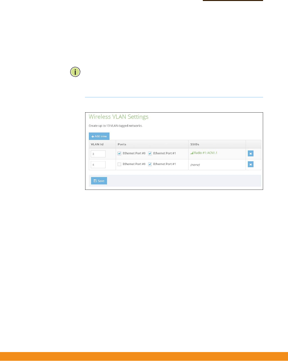
Figure31:ConfiguringVLANs
Thefollowingitemsaredisplayedonthispage:
◆
VLANID—AVLANidentifiertobeassigned.(Range:3‐4095)
(VLAN1and2arereservedforinternaluse.)
◆
Ports
—TheEthernetportsassignedtothespecifiedVLAN.
◆
SSIDs
—TheSSIDofaVAPconfiguredtobeamemberofthespecifiedVLAN.
ThisoptionisconfiguredunderRadioSettings(NetworkSettings–Network
Behavior).

–
52
–
SystemSettings
Thischapterdescribesmaintenancesettingsontheaccesspoint.Itincludesthe
followingsections:
◆
“SystemSettings”onpage53
◆
“Maintenance”onpage54
◆
“UserAccounts”onpage57
◆
“Services”onpage57
5

–
53
–
Chapter5
|
SystemSettings
SystemSettings
SystemSettings
TheSystemSettingspageisusedtoconfiguregeneraldescriptiveinformation
abouttheaccesspoint,suchasthesystemidentificationname,itsgeographic
coordinates,andlocaltime.
Figure32:SystemSettings
Thefollowingitemsaredisplayedonthispage:
◆
DeviceName—AnaliasfortheAP,enablingthedevicetobeuniquely
identifiedonthenetwork.(Default:none;Range:0‐50characters)
◆
DeviceLatitude
—Thegeographiclatitudeoftheaccesspoint,givenin
degreesandminutes.(Range:‐ 90to+90degrees)
◆
DeviceLongitude
—Thegeographiclongitudeoftheaccesspoint,givenin
degreesandminutes.(Range:‐ 180to+180degrees)
◆
Enableresetbutton
—Enablesordisablesthehardwareresetbutton.
◆
LocalTime—Thelocaltime,givenasdayofweek,month,time,year.
◆
ConfigureNetworkTime
—LinkstotheNetworkTime(NTP)sectiononthe
Servicespage.
–
54
–
Chapter5
|
SystemSettings
Maintenance
Maintenance
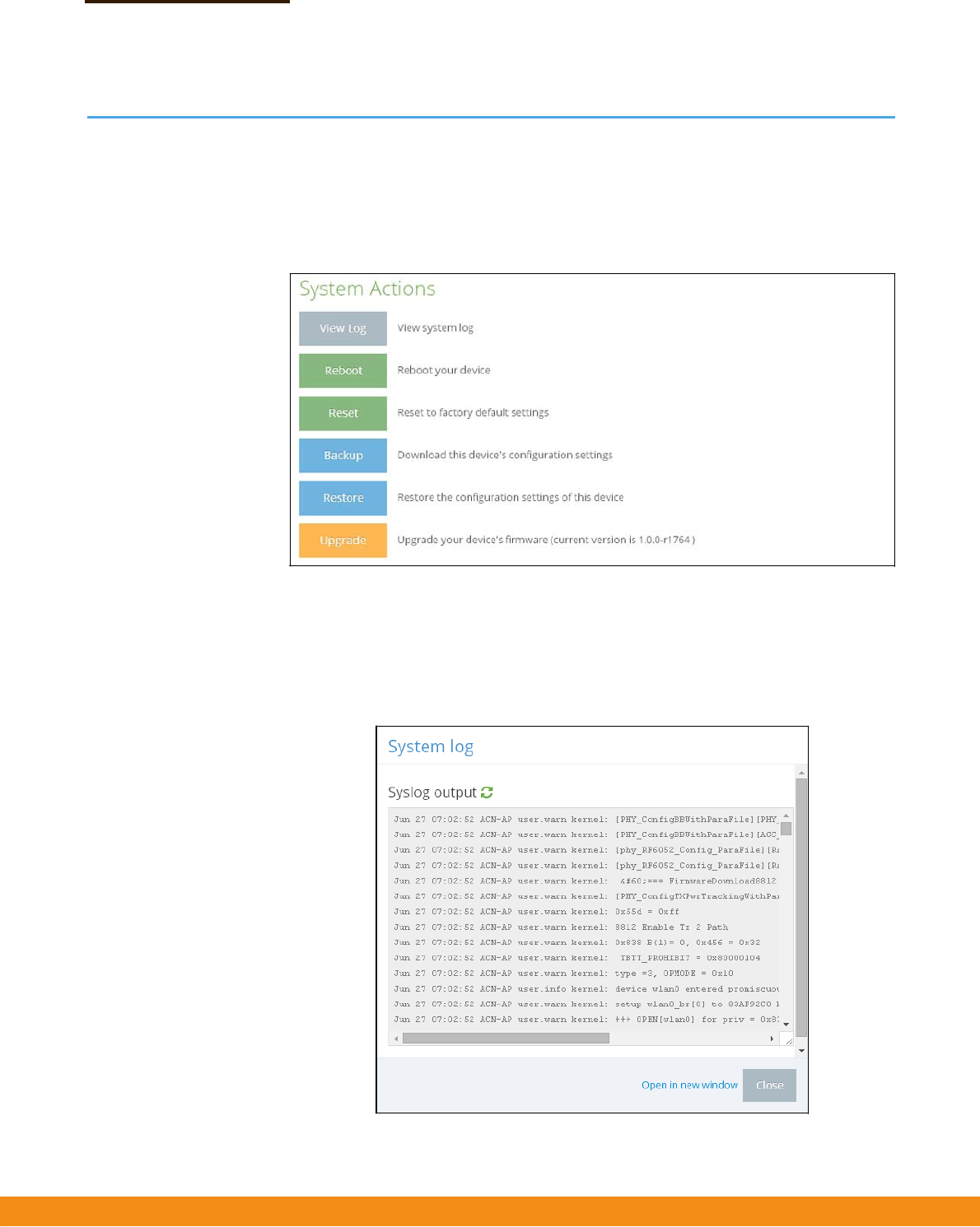
TheMaintenancepagesupportsgeneralmaintenancetasksincludingdisplaying
thesystemlog,rebootingthedevice,restoringfactorydefaults,backingupor
restoringconfigurationsettings,andupgradingfirmware.
Figure33:Maintenance
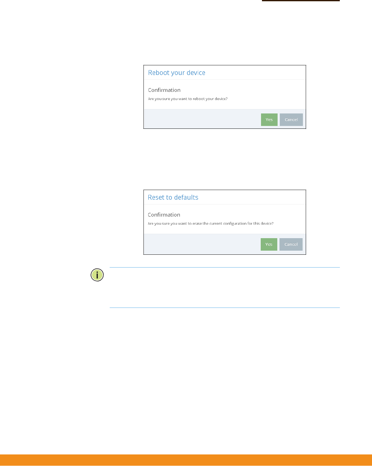
Displaying
SystemLogs
Theaccesspointsaveseventanderrormessagestoalocalsystemlogdatabase.
Thelogmessagesincludethedateandtime,devicename,messagetype,and
messagedetails.
Figure34:SystemLog
–
55
–
Chapter5
|
SystemSettings
Maintenance
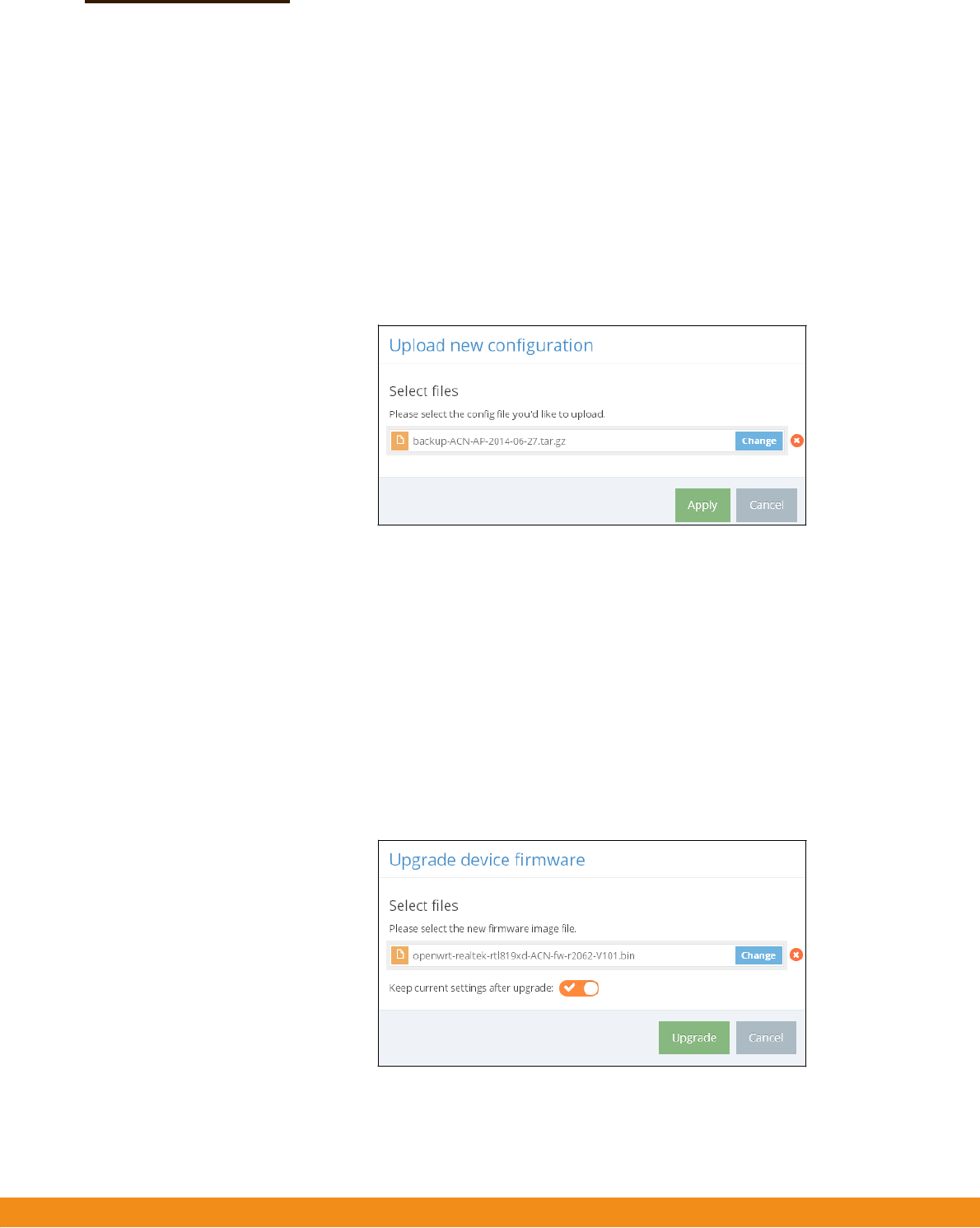
Rebootingthe
AccessPoint
TheRebootpageallowsyoutoreboottheaccesspoint.
Figure35:RebootingtheAccessPoint
Resettingthe
AccessPoint
TheResetpageallowsyoutoresettheaccesspointtothefactorydefaults.Note
thatalluserconfiguredinformationwillbelost.Youwillhavetore‐enterthe
defaultusernameandpasswordtore‐gainmanagementaccesstothisdevice.
Figure36:ResettingtoDefaults
Note:Itisalsopossibletorebootorresettheaccesspointbyinsertingapininthe
pinholelabeled“RESET”ontheconnectorpaneloftheaccesspointand:
◆
press2secondstoreboottheaccesspoint;
◆
press10secondstoresettheaccesspointtothefactorydefaults.
–
56
–
Chapter5
|
SystemSettings
Maintenance
BackingUp
Configuration
Settings
TheBackupfunctionallowsyoutobackuptheaccesspoint’sconfigurationtoa
managementworkstation.InWindows,aGNUZip(*.tar.gz)filewillbestoredinthe
Downloadsfolder.Thisisasamplefilename:backup‐ACN‐AP‐2014‐06‐27.tar.gz
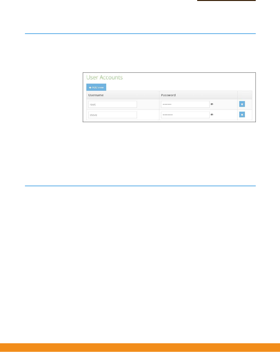
Restoring
Configuration
Settings
TheRestorepageallowsyoutouploadconfigurationsettingsfromamanagement
workstation.Thespecifiedfilemustbeonethatwaspreviouslybackedupfromthe
accesspoint.
Figure37:RestoringConfigurationSettings
UpgradingFirmware Youcanupgradenewaccesspointsoftwarefromalocalfileonthemanagement
workstation.Newsoftwaremaybeprovidedperiodicallyfromyourdistributor.
Afterupgradingnewsoftware,youmustreboottheaccesspointtoimplementthe
newcode.Untilarebootoccurs,theaccesspointwillcontinuetorunthesoftware
itwasusingbeforetheupgradestarted.Theaccesspointsupportsdualsoftware
images,soifnewlyloadedsoftwareiscorrupted,thealternateimagewillbeused
onthenextreboot.Configurationsettingsarestoredseparatelyfromthesoftware,
sothecurrentsettingswillalwaysbeusedforanynewsoftware.However,note
thatifthecurrentconfigurtionsettingsarecorrupted,thesystemdefaultswillbe
used.
Figure38:UpgradingFirmware
–
57
–
Chapter5
|
SystemSettings
UserAccounts
UserAccounts
TheUserAccountspageallowsyoutocontrolmanagementaccesstotheswitch
basedonmanuallyconfiguredusernamesandpasswords.
Figure39:UserAccounts
Thefollowingitemsaredisplayedonthispage:
◆
Username—Thenameoftheuser.(Range:3‐15ASCIIcharacters,nospecial
characters)
◆
Password—Theuserpassword.(Range:3‐15ASCIIcharacters,casesensitive,
nospecialcharacters)
Services
TheServicespageallowsyoutocontrolremotemanagementaccesstotheswitch
andtoconfigureofNTPtimeservers.
RemoteManagement
Settings
TheSSH,Telnet,Web,andSNMPmanagementinterfacesareenabledandopento
accessfromtheInternet.Toprovidemoresecurity,specificservicescanbedisabled
andmanagementaccesspreventedfromtheInternet.
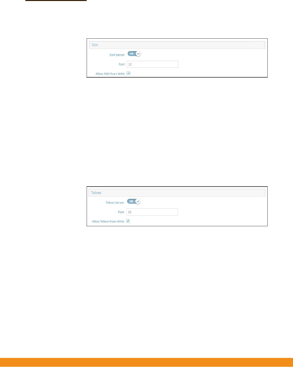
SSH TheSecureShell(SSH)canactasasecurereplacementforTelnet.TheSSHprotocol
usesgeneratedpublickeystoencryptalldatatransferspassingbetweentheaccess
pointandSSH‐enabledmanagementstationclientsandensuresthatdatatraveling
overthenetworkarrivesunaltered.Clientscanthensecurelyusethelocaluser
nameandpasswordforaccessauthentication.
NotethatSSHclientsoftwareneedstobeinstalledonthemanagementstationto
accesstheaccesspointformanagementviatheSSHprotocol.
–
58
–
Chapter5
|
SystemSettings
Services
Figure40:SSHServerSettings
Thefollowingitemsaredisplayedonthispage:
◆
SSHServer
—EnablesordisablesSSHaccesstotheaccesspoint.
(Default:Enabled)
◆
Port—SetstheTCPportnumberfortheSSHserverontheaccesspoint.
(Range:1‐65535;Default:22)
◆
AllowSSHfromWAN
—AllowsSSHmanagementaccessfromtheWAN.
TelnetTelnetisaremotemanagementtoolthatcanbeusedtoconfiguretheaccesspoint
fromanywhereinthenetwork.However,notethatTelnetisnotsecurefromhostile
attacks.
Figure41:TelnetServerSettings
Thefollowingitemsaredisplayedonthispage:
◆
TelnetServer
—EnablesordisablesTelnetaccesstotheaccesspoint.
(Default:Enabled)
◆
Port—SetstheTCPportnumberfortheTelnetserverontheaccesspoint.
(Range:1‐65535;Default:23)
◆
AllowTelnetfromWAN
—AllowsTelnetmanagementaccessfromtheWAN.
WebserverAWebbrowserprovidestheprimarymethodofmanagingtheaccesspoint.Both
HTTPandHTTPSservicecanbeaccessedindependently.IfyouenableHTTPS,you
mustindicatethisintheURL:https://device:port_number]
WhenyoustartHTTPS,theconnectionisestablishedinthisway:

–
59
–
Chapter5
|
SystemSettings
Services
◆
Theclientauthenticatestheserverusingtheserver’sdigitalcertificate.
◆
Theclientandservernegotiateasetofsecurityprotocolstouseforthe
connection.
◆
Theclientandservergeneratesessionkeysforencryptinganddecryptingdata.
◆
Theclientandserverestablishasecureencryptedconnection.
◆
Apadlockiconshouldappearinthestatusbarformostbrowsers.
Figure42:WebServerSettings
Thefollowingitemsaredisplayedonthispage:
◆
HTTPPort—TheTCPporttobeusedbytheHTTPWebbrowserinterface.
(Range:1‐65535;Default:80)
◆
AllowHTTPfromWAN
—AllowsHTTPmanagementaccessfromtheWAN.
◆
HTTPSPort—TheTCPporttobeusedbytheHTTPSWebbrowserinterface.
(Range:1‐65535;Default:443)
◆
AllowHTTPSfromWAN
—AllowsHTTPSmanagementaccessfromtheWAN.
NetworkTime NetworkTimeProtocol(NTP)allowstheaccesspointtosetitsinternalclockbased
onperiodicupdatesfromatimeserver(SNTPorNTP).Maintaininganaccuratetime
ontheaccesspointenablesthesystemlogtorecordmeaningfuldatesandtimes
forevententries.Iftheclockisnotset,theaccesspointwillonlyrecordthetime
fromthefactorydefaultsetatthelastbootup.
TheaccesspointactsasanNTPclient,periodicallysendingtimesynchronization
requeststospecifiedtimeservers.Theaccesspointwillattempttopolleachserver
intheconfiguredsequence.
–
60
–
Chapter5
|
SystemSettings
Services
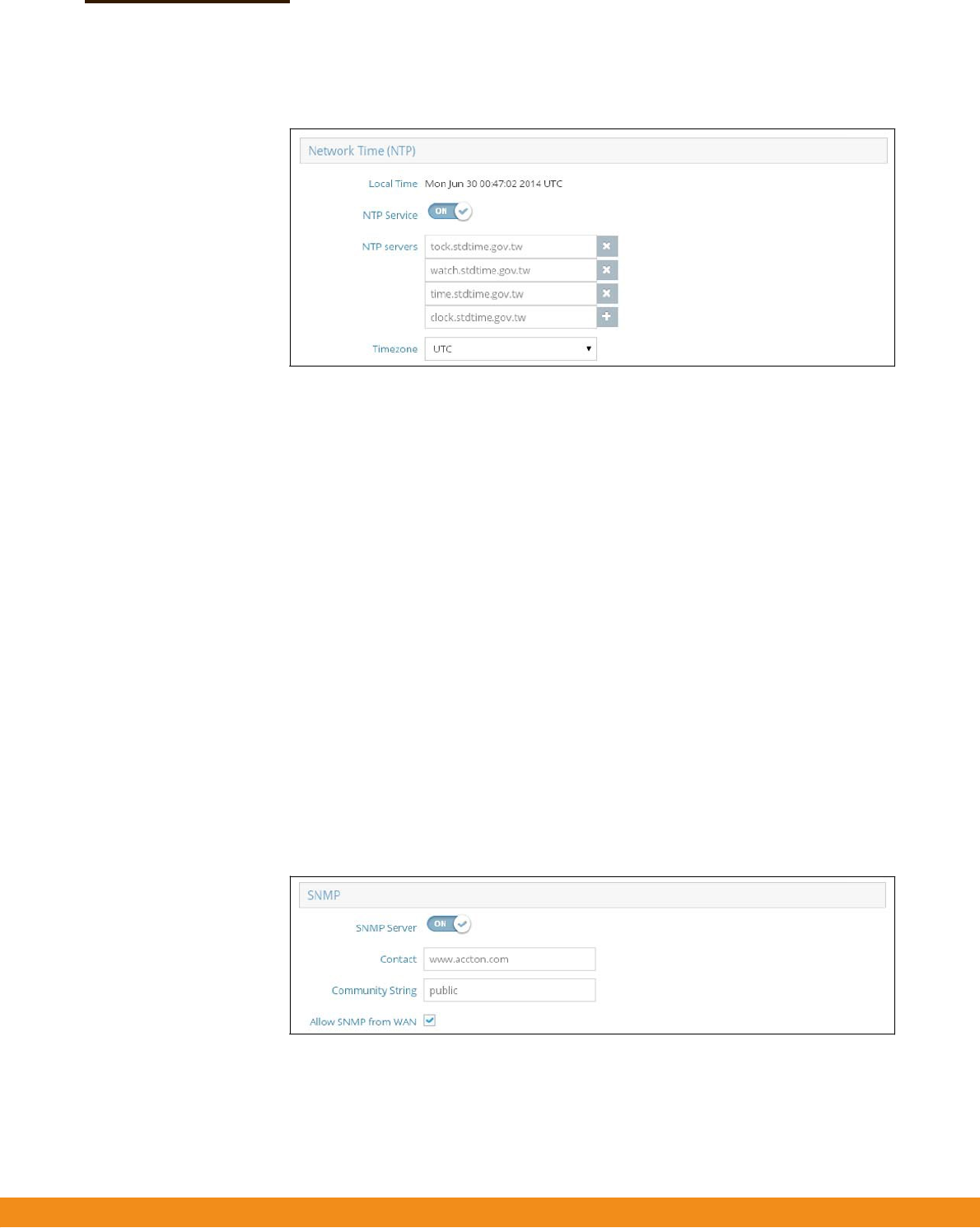
Figure43:NTPSettings
Thefollowingitemsaredisplayedonthispage:
◆
LocalTime—Displaysthelocaltimeasdayofweek,month,
hour:minute:second,year,basedonUniversalTimeCoordinates.
◆
NTPService—Enablesordisablessendingofrequestsfortimeupdates.
(Default:Enabled)
◆
NTPServers—Setsthehostnamesfortimeservers.Theswitchattemptsto
updatethetimefromthefirstserver,ifthisfailsitattemptsanupdatefromthe
nextserverinthesequence.Toconfigureadditionalservers,clickthe“+”
buttontoopenaneweditfield.
◆
TimeZone
—Todisplayatimecorrespondingtoyourlocaltime,chooseone
ofthepredefinedtimezonesfromthescroll‐downlist.
SNMPSimpleNetworkManagementProtocol(SNMP)isacommunicationprotocol
designedspecificallyformanagingdevicesonanetwork.Itistypicallyusedto
configurethesedevicesforproperoperationinanetworkenvironment,aswellas
tomonitorthemtoevaluateperformanceordetectpotentialproblems.
Figure44:SNMPSettings
Thefollowingitemsaredisplayedonthispage:
◆
SNMPServer
—EnablesordisablesSNMPontheaccesspoint.
(Default:Enabled)

–
61
–
Chapter5
|
SystemSettings
Services
◆
Contact—Administratorresponsiblefortheaccesspoint.
◆
CommunityString—Acommunitystringthatactslikeapasswordand
permitsaccesstotheSNMPprotocol.(Range:1‐32characters,casesensitive;
Default:public)
Thedefaultstring“public”providesread‐onlyaccesstotheaccesspoint’s
ManagementInformation(MIB)database.
◆
AllowSNMPfromWAN
—AllowsSNMPmanagementaccessfromtheWAN.

–
61
–
Appendices
Thissectionprovidesadditionalinformationandincludestheseitems:
◆
“Troubleshooting”onpage62
SectionIII

–
62
–
Tro u b l e s h o o t i n g
ProblemsAccessingtheManagementInterface
Table5:TroubleshootingChart
Cannotconnectusing
Telnet,webbrowser,or
SNMPsoftware
◆
BesuretheAPispoweredup.
◆
Checknetworkcablingbetweenthemanagementstationandthe
AP.
◆
CheckthatyouhaveavalidnetworkconnectiontotheAPand
thatintermediateswitchportshavenotbeendisabled.
◆
BesureyouhaveconfiguredtheAPwithavalidIPaddress,subnet
maskanddefaultgateway.
◆
BesurethemanagementstationhasanIPaddressinthesame
subnetastheAP’sIP.
◆
IfyouaretryingtoconnecttotheAPusingataggedVLANgroup,
yourmanagementstation,andtheportsconnectingintermediate
switchesinthenetwork,mustbeconfiguredwiththeappropriate
tag.
◆
IfyoucannotconnectusingTelnet,youmayhaveexceededthe
maximumnumberofconcurrentTelnet/SSHsessionspermitted.
Tryconnectingagainatalatertime.
Forgotorlostthepassword◆ ResettheAPtofactorydefaultsusingitsResetbutton.
UsingSystemLogs
Ifafaultdoesoccur,refertotheQuickStartGuidetoensurethattheproblemyou
encounteredisactuallycausedbytheAP.Iftheproblemappearstobecausedby
theAP,followthesesteps:
1.
EnableSNMPintheSystem>Servciesmenu.
2.
EnableSNMPaccessfromtheWANwhenconnectingfromaremotelocation.
3.
Repeatthesequenceofcommandsorotheractionsthatleaduptotheerror.
4.
Makealistofthecommandsorcircumstancesthatledtothefault.Alsomakea
listofanyerrormessagesdisplayed.
5.
Recordallrelevantsystemsettings.
Symptom
Action
A

–
63
–
ChapterA
|
Troubleshooting
UsingSystemLogs
6.
DisplaythelogfilethroughtheSystem>Maintenancemenu,andcopythe
informationfromthelogfile.
7.
Contactyourdistributor’sserviceengineer,andsendadetaileddescriptionof
theproblem,alongwithalloftheinformationmentionedintheabovesteps.

–
64
–
QuickStart Guide
–
2
–
FollowthestepsinthisguidetoinstalltheAPinyournetwork.
Caution:
TheplanningandinstallationoftheAPrequiresprofessionalpersonnel
thataretrainedintheinstallationofradiotransmittingequipment.Theuseris
responsibleforcompliancewithlocalregulationsconcerningitemssuchas
antennapower,useoflightningarrestors,grounding,andradiomastortower
construction.Therefore,itisrecommendedtoconsultaprofessionalcontractor
knowledgeableinlocalradioregulationspriortoequipmentinstallation.
1.
UnpacktheAP
UnpacktheAPandcheckthepackagecontents.
◆
OutdoorStand‐AloneAccessPoint
SkyFireAC1200orSkyFireAC866
◆
Pole‐mountingkit—includestwosteel‐bandclamps
◆
PoEpowerinjectorwithpowercord—eitherUS,ContinentalEuropeorUK
◆
Documentation—QuickStartGuideandRegulatoryandSafetyInformation
2.
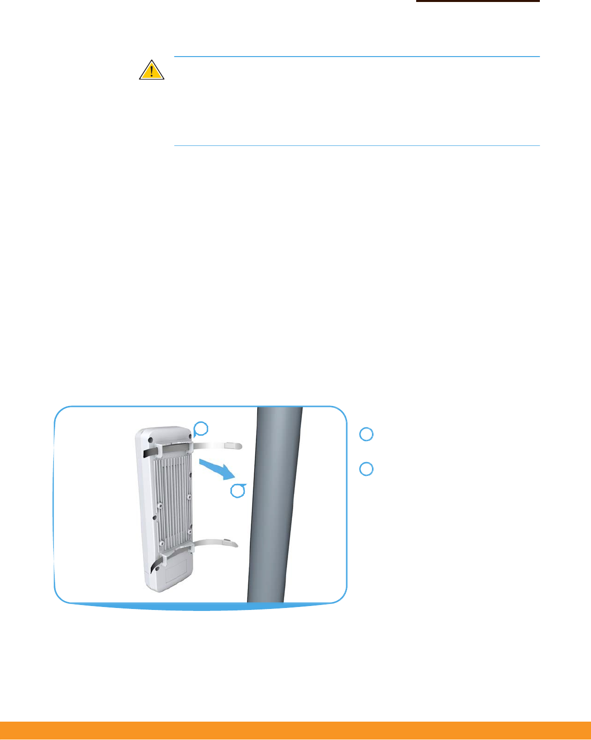
MounttheAP Afterplanningyourinstallation,mounttheunitonapole,mast,ortowerusingthe
includedtwosteel‐bandclamps.
Also,formodelsthatrequireexternalantennas,installtheantennasneartheAP
andattachtheRFcoaxialcablestotheappropriateconnectorsontheAP.
PoleMounting
Feedthesteel‐bandclampsthroughthe
integratedpole‐mountbracketpointson
thebackoftheAP.
Fastenthesteel‐bandclampsaroundthe
poletosecuretheAPtothepole.
1
2
1
2
QuickStart Guide
–
3
–
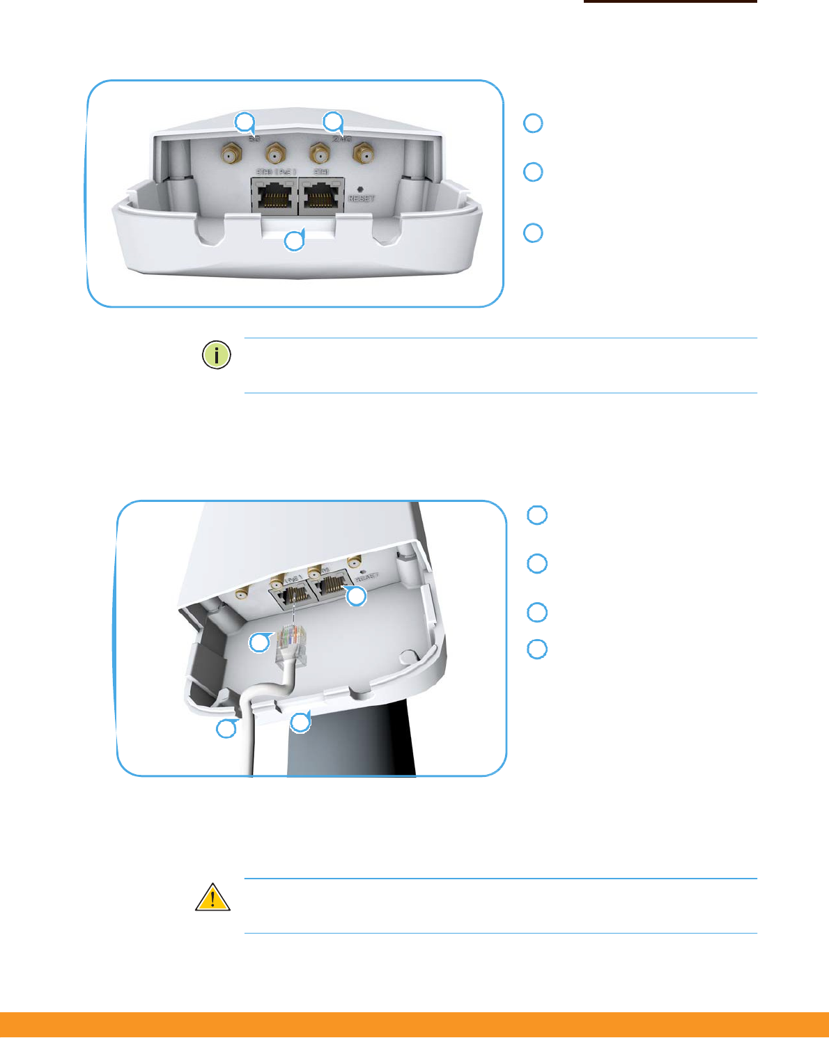
AttachExternalAntennas
Removethefrontportcoverby
pushingthelockingtabupandthen
slidingthecoveroff.
Connectexternalantennastothe
AP’s5GHzRP‐SMAconnectorsusing
RFcoaxialcableprovidedinthe
antennapackage.
Connectexternalantennastothe
AP’s2.4GHzRP‐SMAconnectors
usingRFcoaxialcableprovidedinthe
antennapackage.
Note:Thenumberofavailable2.4GHzor5GHzexternalantennaconnectors
dependsonthespecificmodel.
3.
ConnectCablesConnectoutdoor‐ratedEthernetcabletothe1000BASE‐TRJ‐45ETH0(PoE)porton
theunit.
Connectoutdoor‐ratedCategory5e
orbettercabletotheleft‐sideRJ‐45
ETH0(PoE)port.
(Optional)ConnectalocalLAN
switchorcomputertotheright‐side
ETH1100BASE‐TXRJ‐45port.
Passthecablesthroughtheaccess
holesatthebottomoftheAP.
ReplacetheportcoverontheAPand
pushthelockingtabdowntosecure
itinplace.
4.
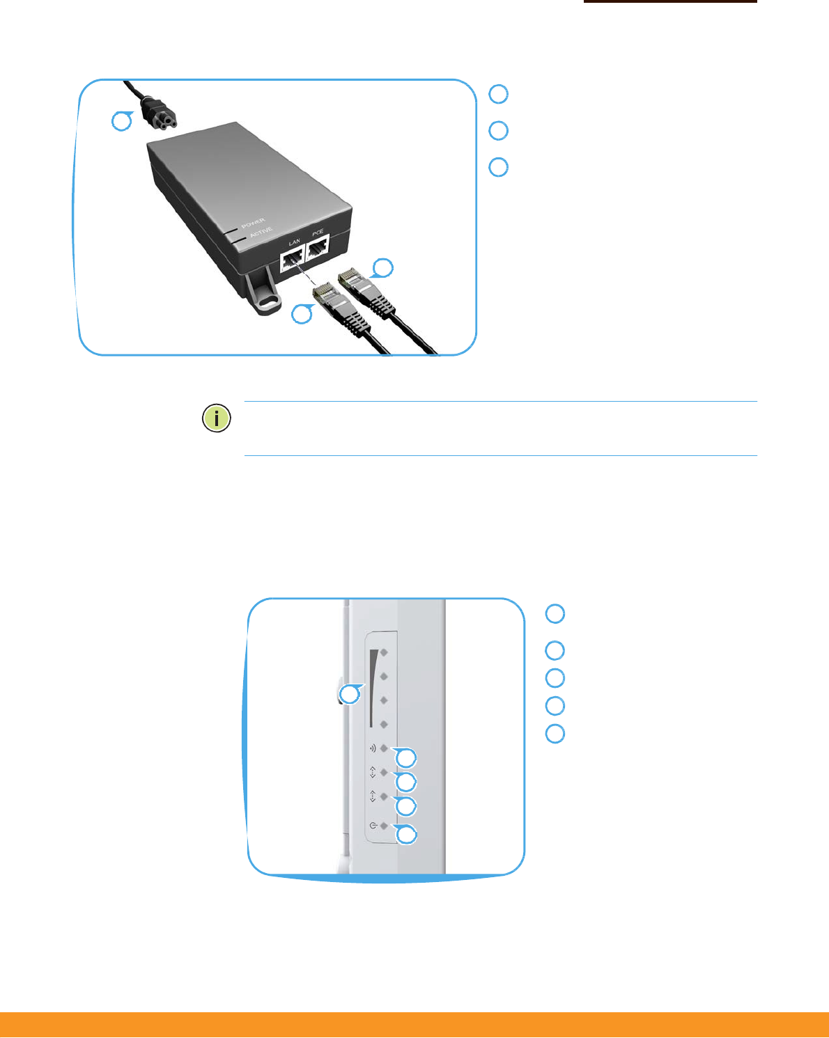
ConnectPower InstallthePoEpowerinjectorindoors.ConnectthepowerinjectortotheEthernet
cablefromtheAP,toaportonalocalLANswitch,andthentoanACpowersource.
Caution:
Thepowerinjectormoduleisdesignedforindooruseonly.Nevermount
thepowerinjectoroutsidewiththeAPunit.
23
1
1
2
3
1
2
2
3
14
34
QuickStart Guide
–
4
–
ConnecttheEthernetcablefromtheAPto
the“POE”portonthepowerinjector.
ConnectEthernetcablefromthe“LAN”port
onthepowerinjectortoaLANswitch.
ConnectthepowercordtoanearbyAC
powersource(100‐240VAC,50/60Hz).
Note
:
ConnectingtheEthernetcablefromtheAPtotheinjectormodulepowers
ontheunit.
5.
VerifyAPOperation
VerifybasicAPoperationbycheckingthesystemLEDs.
ThepowerLEDshouldbeongreen,theETH0portLEDon/blinkinggreen,andthe
2.4GHz/5GHzwirelessLEDon/blinkinggreen(2.4GHz)orblue(5GHz).
2.4GHz/5GHzsignalstrength
LEDs.
2.4GHz/5GHzlink/activityLED.
ETH1portlink/activityLED.
ETH0(PoE)portlink/activityLED.
PowerLED.
1
3
2
3
1
2
1
2
3
4
5
1
2
3
4
5

QuickStart Guide
–
5
–
6.
ConnecttotheWeb
UserInterface
Thestand‐aloneAPsofferaweb‐basedmanagementinterfaceforthe
configurationofalltheunit’sfeatures.
YoucanmakeinitialconfigurationchangesbyconnectingaPCdirectlytotheAP’s
ETH1RJ‐45port.TheAPhasadefaultmanagementIPaddressof192.168.2.1anda
subnetmaskof255.255.255.0.YoumustsetyourPCIPaddresstobeonthesame
subnetastheAP(thatis,thePCandAPaddressesmustbothstart192.168.2.x).
Logintothewebinterfaceusingthedefaultsettings:
◆
LoginName—root
◆
Password—admin123
Formoreinformationonstand‐aloneAPconfigurationusingthewebinterface,
refertotheManagementGuide.

QuickStart Guide
–
6
–
HardwareSpecifications
Chassis
Size(HxWxD:)283x94x50mm(11.14x3.7x1.97inches)
Weight
762g(1.68lb)
TemperatureOperating:‐20°Cto65°C(‐4°Fto149°F)
Storage:‐30°Cto80°C(‐22°Fto176°F)
Humidity
Operating:15%to95%(non‐condensing)
Waterproof/Dustproof
IP55
NetworkInterfaces
PortsETH0(PoE)RJ‐45Port:1000BASE‐T,passivePoE
ETH1RJ‐45Port:100BASE‐TX
2.4GHzRadioIEEE802.11b/g/n
5GHzRadioIEEE802.11a/n/ac
RadioFrequencies2412~2472MHz
5745~5825MHz(China)
5180~5320MHz(ETSI)
5500~5700MHz(ETSI)
PowerSupply
PoEInputPower24VDC,1.0A
PowerConsumption24Wmaximum
PowerInjectorModule100‐240VAC,50‐60Hz,auto‐sensing
RegulatoryCompliances
RadioEN300328V1.8.1:2012
EN301893V1.7.1:2012
EN301489‐1V1.9.2(2011‐09)
EN301489‐7V1.3.1:2005
FCCPart15C15.247/15.207(2.4‐2.4835GHz,5.725‐5.850GHz)
FCCPart15E15.407(5.150GHz‐5.250GHz)
EmissionsEN550222010+AC:2011
EN61000‐3‐22006+A1:2009+A2:2009
FCCClassBPart15
ImmunityEN55024:2010
EN61000‐4‐2:2009
ItemSpecification

QuickStart Guide
–
7
–
FederalCommunicationCommissionInterferenceStatement
ThisdevicecomplieswithPart15oftheFCCRules.Operationissubjecttothefollowingtwoconditions:(
1)Thisdevicemaynotcauseharmfulinterference,and
(2)thisdevicemustacceptanyinterferencereceived,includinginterferencethatmaycauseundesiredoperation.
ThisequipmenthasbeentestedandfoundtocomplywiththelimitsforaClassBdigitaldevice,pursuanttoPart15
oftheFCCRules.Theselimitsaredesignedtoprovidereasonableprotectionagainstharmfulinterferenceina
residentialinstallation.Thisequipmentgenerates,usesandcanradiateradiofrequencyenergyand,ifnotinstalled
andusedinaccordancewiththeinstructions,maycauseharmfulinterferencetoradiocommunications.However,
thereisnoguaranteethatinterferencewillnotoccurinaparticularinstallation.Ifthisequipmentdoescause
harmfulinterferencetoradioortelevisionreception,whichcanbedeterminedbyturningtheequipmentoffandon,
theuserisencouragedtotrytocorrecttheinterferencebyoneofthefollowingmeasures:
‐ Reorientorrelocatethereceivingantenna.
‐ Increasetheseparationbetweentheequipmentandreceiver.
‐ Connecttheequipmentintoanoutletonacircuitdifferentfromthat
towhichthereceiverisconnected.
‐ Consultthedealeroranexperiencedradio/TVtechnicianforhelp.
FCCCaution:Anychangesormodificationsnotexpresslyapprovedbythepartyresponsibleforcompliancecouldvoid
theuser'sauthoritytooperatethisequipment.
Thistransmittermustnotbeco‐locatedoroperatinginconjunctionwithanyotherantennaortransmitter.
Foroperationwithin5.15~5.25GHz/5.47~5.725GHzfrequencyrange,itisrestrictedtoindoorenvironment.
Thebandfrom5600‐5650MHzwillbedisabledbythesoftwareduringthemanufacturingandcannotbechanged
bytheenduser.ThisdevicemeetsalltheotherrequirementsspecifiedinPart15E,Section15.407oftheFCCRules.
RadiationExposureStatement:
ThisequipmentcomplieswithFCCradiationexposurelimitssetforthforanuncontrolledenvironment.
Thisequipmentshouldbeinstalledandoperatedwithminimumdistance20cmbetweentheradiator&yourbody.
Note:Thecountrycodeselectionisfornon‐USmodelonlyandisnotavailabletoallUSmodel.
PerFCCregulation,allWiFiproductmarketedinUSmustfixedtoUSoperationchannelsonly.

QuickStart Guide
–
8
–
Professionalinstallationinstruction
1. Installationpersonal
ThisproductisdesignedforspecificapplicationandneedstobeinstalledbyaqualifiedpersonalwhohasRFand
relatedruleknowledge.Thegeneralusershallnotattempttoinstallorchangethesetting.
2. Installationlocation
Theproductshallbeinstalledatalocationwheretheradiatingantennacanbekept20cmfromnearbypersonin
normaloperationconditiontomeetregulatoryRFexposurerequirement.
3. Externalantenna
Useonlytheantennaswhichhavebeenapprovedbytheapplicant.Thenon‐approvedantenna(s)mayproduce
unwantedspuriousorexcessiveRFtransmittingpowerwhichmayleadtotheviolationofFCClimitandisprohibited.
4. Installationprocedure
Pleaserefertouser’smanualforthedetail.
5. Warning
Pleasecarefullyselecttheinstallationpositionandmakesurethatthefinaloutputpowerdoesnotexceedthe
limitsetforceinrelevantrules.Theviolationoftherulecouldleadtoseriousfederalpenalty.
低功率電波輻射性電機管理辦法
第十二條 經型式認證合格之低功率射頻電機,非經許可,公司、商號或使用者均不得擅自變更頻率、
加大功率或變更原設計之特性及功能。
第十四條 低功率射頻電機之使用不得影響飛航安全及干擾合法通信;經發現有干擾現象時,應立即停用,
並改善至無干擾時方得繼續使用。前項合法通信,指依電信法規定作業之無線電通信。低功率射頻電機須忍受合法通信或工業、
科學及醫療用電波輻射性電機設備之干擾。
此器材須經專業安裝並限用於固定式點對點操作。
本器材須經專業工程人員安裝及設定,始得設置使用,且不得直接販售給一般消費者。
「電磁波曝露量MPE標準值1mW/cm2,送測產品實測值為 0.736 mW/cm2」
To professional installer : Installer must disable UNII band 1 by tool when you install this device for outdoor
usage for complying with FCC rule.