Accton Technology AC866 5GHz Outdoor AP, 802.11ac Outdoor 5GHz Access Point User Manual SF AC866 FCC Manual 20150506
Accton Technology Corp 5GHz Outdoor AP, 802.11ac Outdoor 5GHz Access Point SF AC866 FCC Manual 20150506
User Manual rev.pdf

QuickStartGuide
Brand:IgniteNet
TheAC866is5GHzOutdoor/IndoorAPaccesspoints(APs)thatarehousedina
waterproofenclosureformountingoutdoors.Theunitsincludeabuilt‐in
mountingbracketforattachingtoa1.5to6‐inchpoleandtheycanbepowered
throughtheirEthernetcableconnectionfromapowerinjectormodulethatis
installedindoors.
TheOutdoorStand‐AloneAccessPointsincludethesemodels:
◆ SF‐AC866‐ 5GHzOutdoor/IndoorAP
Note:ForSafetyandRegulatoryinformation,refertotheSafetyandRegulatory
InformationdocumentincludedwiththeAP.
www.ignitenet.com

–
12
–
–
GettingStarted
Thissectionprovidesanoverviewoftheaccesspoint,andintroducessomebasic
conceptsaboutwirelessnetworking.Italsodescribesthebasicsettingsrequiredto
accessthemanagementinterface.
Thissectionincludesthesechapters:
◆
“Introduction”onpage12
SectionI

–
13
–
Introduction
Theaccesspoint(AP)runssoftwarethatincludesanetworkmanagementagent.
Theagentoffersavarietyofmanagementoptions,includingSNMPandaweb‐
basedinterface.TheAPcanalsobeaccessedviaTelnetorSSHforconfiguration
usingacommandlineinterface(CLI).
ConfigurationOptions
Theaccesspoint’swebagentallowsyoutoconfigureAPparameters,monitor
wirelessconnections,anddisplaystatisticsusingastandardwebbrowsersuchas
InternetExplorer9.xorlater,MozillaFirefox5orlater,andGoogleChrome35or
later.TheAP’swebmanagementinterfacecanbeaccessedfromanycomputer
attachedtothenetwork.
TheCLIprogramcanbeaccessedremotelybyaTelnetorSecureShell(SSH)
connectionoverthenetwork.TheCLIisusedprimarilyfortechnicalsupport.
TheAP’smanagementagentalsosupportsSNMP(SimpleNetworkManagement
Protocol).ThisSNMPagentpermitstheAPtobemanagedfromanycomputerin
thenetworkusingnetworkmanagementsoftware.
TheAP’swebinterface,consoleinterface,andSNMPagentallowyoutoperform
managementfunctionssuchas:
◆
Setmanagementaccessusernamesandpasswords
◆
ConfigureIPsettings
◆
ConfigureSNMPparameters
◆
Configure5GHzradiosettings
◆
Controlaccessthroughwirelesssecuritysettings
◆
FilterpacketsusingAccessControlLists(ACLs)
◆
Downloadsystemfirmware
◆
Downloadoruploadconfigurationfiles
◆
Displaysysteminformationandstatistics
1

–
14
–
Chapter1
|
Introduction
NetworkConnections
NetworkConnections
PriortoaccessingtheAP’smanagementagentthroughanetworkconnection,you
mustfirstconfigureitwithavalidIPaddress,subnetmask,anddefaultgateway
usingthewebinterface,ortheDHCPprotocol.
TheAPhasastaticdefaultmanagementaddressof192.168.2.1andasubnetmask
of255.255.255.0.IftheAP’sdefaultIPaddressisnotcompatiblewithyournetwork
oraDHCPserverisnotavailable,theAP’sIPaddressmustbeconfiguredmanually
throughthewebinterface.
FirstconnecttotheAP’sEthernet1portandlogintothewebinterface,as
describedin“ConnectingtotheWebInterface”onpage13.Followthesteps
describedin“SetupWizard”onpage15toselectyourcountryandspecifyoneof
theconfigurationmethods.ThenconfiguretheAPwithanIPaddressthatis
compatiblewithyournetworkasdescribedunder“LANSettings”onpage33.
OncetheAP’sIPsettingsareconfiguredforyournetwork,youcanaccesstheAP’s
managementagentfromanywherewithintheattachednetwork.TheAPcanbe
managedbyanycomputerusingawebbrowser,orfromanetworkcomputerusing
SNMPnetworkmanagementsoftware.
ConnectingtotheWebInterface
TheAPoffersauser‐friendlyweb‐basedmanagementinterfaceforthe
configurationofalltheunit’sfeatures.AnyPCdirectlyattachedtotheunitcan
accessthemanagementinterfaceusingawebbrowser,suchasInternetExplorer
9.xorlater,MozillaFirefox5orlater,andGoogleChrome35orlater.
YoumaywanttomakeinitialconfigurationchangesbyconnectingaPCdirectlyto
theAP’sLANport.TheAPhasadefaultmanagementIPaddressof192.168.2.1and
asubnetmaskof255.255.255.0.YoumustsetyourPCIPaddresstobeonthesame
subnetastheAP(thatis,thePCandAPaddressesmustbothstartwith192.168.2.x).
ToaccesstheAP’swebmanagementinterface,followthesesteps:
1.
Useyourwebbrowsertoconnecttothemanagementinterfaceusingthe
defaultIPaddressof192.168.2.1.
2.
Logintotheinterfacebyenteringthedefaultusername“root”withthe
password“admin123”,thenclickLogin.

–
15
–
Chapter1
|
Introduction
ConnectingtotheWebInterface
Note:
Itisstronglyrecommendedtochangethedefaultusernameandpassword
thefirsttimeyouaccessthewebinterface.Forinformationonchanginguser
namesandpasswords,see“UserAccounts”onpage57.
Figure1:LoginPage
–
16
–
Chapter1
|
Introduction
SetupWizard
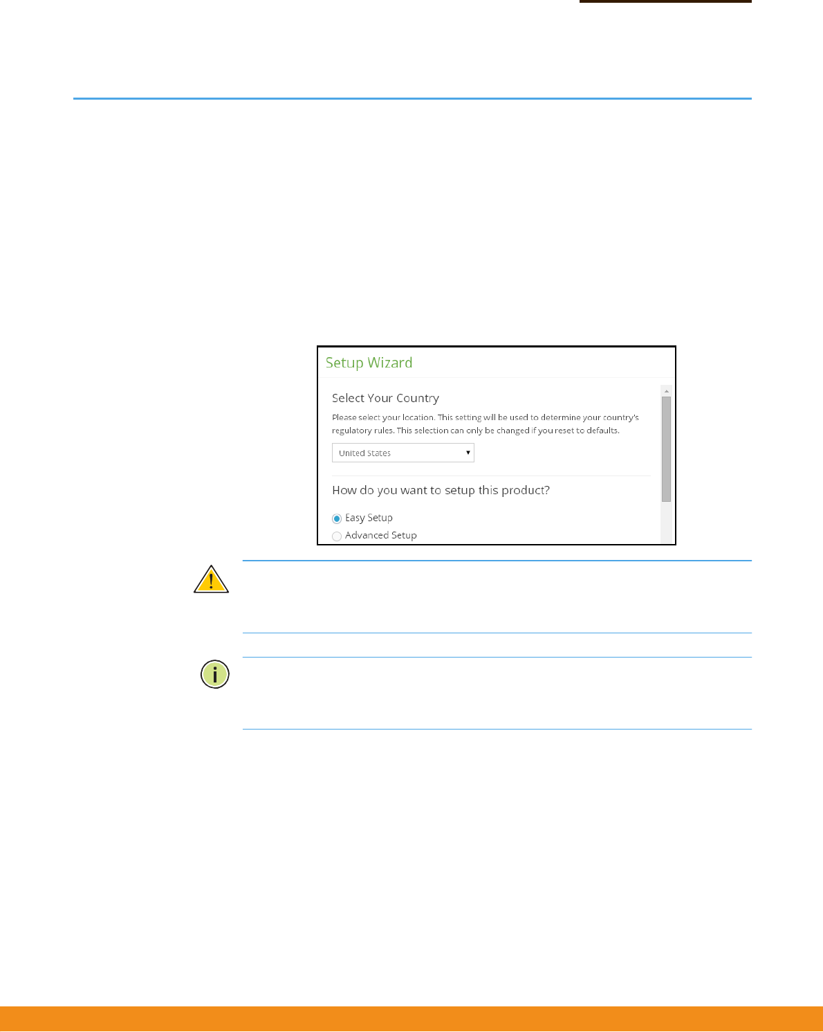
SetupWizard
TheSetupWizardisdesignedtohelpyouconfigurethebasicsettingsrequiredto
gettheAPupandrunning.
Step1 SelectYourCountry–Selecttheaccesspoint’scountryofoperationfromthedrop‐
downmenu.YoumustsettheAP’scountrycodetobesurethattheradiosoperate
accordingtopermittedlocalregulations.Thatis,settingthecountrycoderestricts
operationoftheAPtotheradiochannelsandtransmitpowerlevelspermittedfor
wirelessnetworksinthespecifiedcountry.
Figure2:SelectYourCountry
Caution:
Youmustsetthecountrycodetothecountryofoperation.Settingthe
countrycodeensuresthattheradiosoperatewithinthelocalregulationsspecified
forwirelessnetworks.
Note:Thecountrycodeselectionisfornon‐USmodelsonlyandisnotavailableto
allUSmodels.PerFCCregulation,allWi‐FiproductsmarketedintheUSmustbe
fixedtoUSoperationchannelsonly.
–
17
–
Chapter1
|
Introduction
SetupWizard
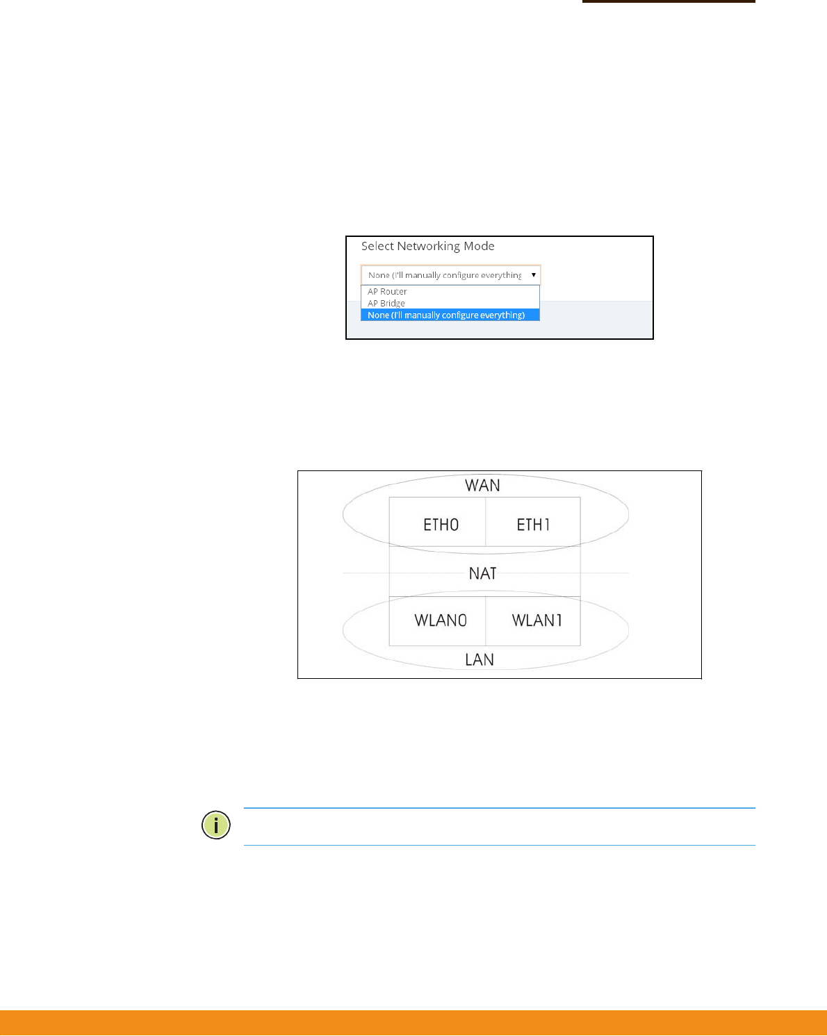
Step2 SelectSetupMethod–SelectEasySetuptosetbasicwirelessnetworkaccessand
guestnetworkaccessparameters,orAdvancedSetuptospecifynetworkingmodes
foranAPbridge,AProuter,ormanualconfiguration.
Figure3:SelectSetupMethod
Step3
ConfigureSettings
◆
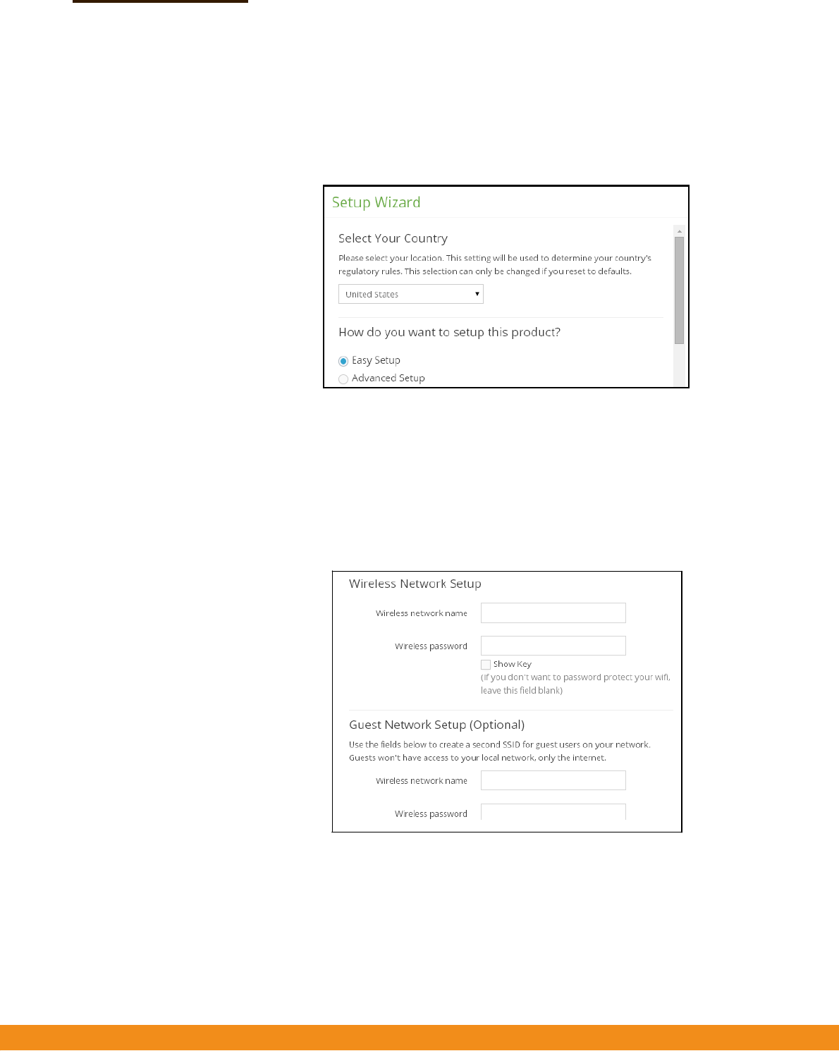
EasySetup—Basicwirelessnetworkandguestnetworkaccessparameters.
Specifythenameandpasswordforthewirelessnetworkandguestnetwork.
TheNetworkingModeissettoAPRouterasdescribedunderAdvancedSetup.
Figure4:EasySetup
■
WirelessNetworkSetup—Setthenameandpasswordfortheprimary
wirelessnetwork.Apasswordmustbespecifiedtoprotectthenetwork
fromunauthorizedaccess.
–
18
–
Chapter1
|
Introduction
SetupWizard
■
GuestNetworkSetup—Setthenameandpasswordfortheguestwireless
network.ThiscreatesasecondSSIDforguestusers,limitingtheiraccess
onlytotheInternet.
◆
AdvancedSetup—NetworkingmodesforAPBridge,APRouter,ormanual
configuration.
Figure5:AdvancedSetup
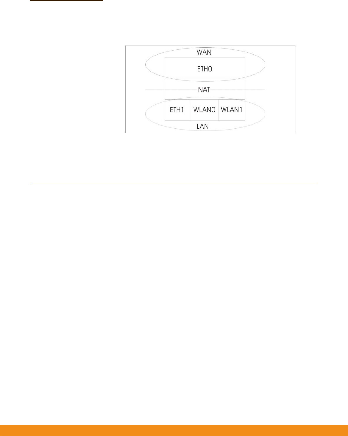
■
APBridgeMode—ConfiguresaninterfaceasattachedtotheWAN(thatis,
theInternet).Inthefollowingfigure,EthernetPort0andEthernetPort1are
bothattachedtotheWAN.Trafficfromtheseinterfacesisdirectlybridged
intotheInternet.(ThisisalsocalledbridgetoInternet.)
Figure6:BridgetoInternet
■
APRouterMode—ConfiguresaninterfaceasamemberoftheLAN.Inthe
followingfigure,EthernetPort1,WirelessLAN0(5GHzRadio),andWireless
LAN1(2.4GHzRadio)areallincludedintheLAN.Trafficfromthese
interfacesisroutedacrosstheaccesspointthroughEthernetPort0tothe
Internet.(ThisisalsocalledroutetoInternet.)
Note:
Single‐bandaccesspointsonlysupportoneWLAN.
–
19
–
Chapter1
|
Introduction
MainMenu
Figure7:RoutetoInternet
■
ManualMode—Allowsallconfigurationparameterstobemanually
configured.Anywiredmoduleorradiomodulemaybelogicallyplacedon
theWANandLANsideoftheaccesspoint.
MainMenu
ThewebinterfaceMainMenuprovidesaccesstoalltheconfigurationsettings
availablefortheAP.
Toconfiguresettings,clicktherelevantMainMenuitem.EachMainMenuitemis
summarizedbelowwithlinkstotherelevantsectioninthisguidewherethe
configurationparametersaredescribedindetail:
◆
Dashboard—ThedashboardshowsbasicsettingsfortheAP,including
Internetstatus,localnetworksettings,wirelessradiostatus,andtrafficgraphs.
See“StatusInformation”onpage22.
◆
Network
—ConfiguresInternet,Ethernet,LAN,andHotspotsettings.See
“NetworkSettings”onpage28.
◆
Wireless
—Configures5GHzRadio,2.4GHzRadio,andVLANsettings.See
“WirelessSettings”onpage37
◆
System
—ConfiguresSystem(designationandlocation),Maintenance(suchas
viewlog,firmwareupgrade,andreset),UserAccounts,andServices
(managementaccessmethods).
–
20
–
Chapter1
|
Introduction
MainMenu
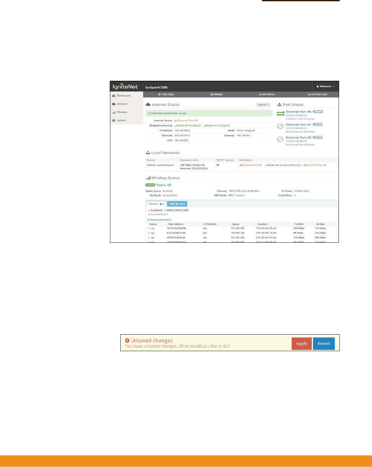
Dashboard Afterloggingintothewebinterface,thedashboarddisplays.Thedashboardshows
basicsettingsfortheAP,includingInternetstatus,localnetworksettings,wireless
radiostatus,andtrafficgraphs.
Figure8:TheDashboard
CommonWebPage
Buttons
Thelistbelowdescribesthecommonbuttonsfoundonmostoftheweb
managementpages:
◆
Save
–AppliesthenewparametersandsavesthemtotemporaryRAM
memory.Alsodisplaysamessageatthetopofthescreentoinformyouthatthe
changeshavenotyetbeensavedtoFlashmemory.Therunningconfiguration
will
not
besaveduponarebootunlessyouclickthe“Apply”button.
Figure9:SetConfigurationChanges
◆
Apply
–Savesthecurrentconfigurationsothatitisretainedafterarestart.
◆
Revert–Cancelsthenewlyenteredsettingsandrestorestheoriginals.
◆
Welcome>Logout
–OpentheWelcomelistandclickLogouttoendtheweb
managementsession.
◆
Welcome>ViewUsers
–OpentheWelcomelistandclickViewUserstoopen
theUserAccountsmenu.

–
20
–
Chapter1
|
Introduction
MainMenu

–
21
–
WebConfiguration
Thissectionprovidesdetailsonconfiguringtheaccesspointusingtheweb
browserinterface.
Thissectionincludesthesechapters:
◆
“StatusInformation”onpage22
◆
“NetworkSettings”onpage28
◆
“WirelessSettings”onpage37
◆
“SystemSettings”onpage52
SectionII

–
22
–
StatusInformation
TheDashboarddisplaysinformationonthecurrentsystemconfiguration,including
Internetstatus,localnetworksettings,wirelessradiostatus,andtrafficgraphs.
StatusInformationincludesthefollowingsections:
◆
“SystemandProductInformation”onpage22
◆
“InternetStatus”onpage22
◆
“LocalNetworks”onpage24
◆
“WirelessStatus”onpage25
◆
“TrafficGraphs”onpage27
SystemandProductInformation
TheSystemandProductInfosectionshowsdescriptiveinformationabouttheAP.
Figure10:SystemandProductInformation
Thefollowingitemsaredisplayedinthissection:
◆
Themodelnameoftheunit.
◆
Thesoftwareversionnumber.
◆
Theserialnumberofthephysicalaccesspoint.
◆
Lengthoftimethemanagementagenthasbeenup.
◆
Thelast1‐minute,5‐minuteand15‐minuteCPUloadaverage.
InternetStatus
TheInternetStatussectionshowsinformationabouttheInternetconnection.
2

–
23
–
Chapter2
|
StatusInformation
InternetStatus
Figure11:InternetStatus
Thefollowingitemsaredisplayedinthissection:
◆
InternetSource
—TheEthernetportconnectedtotheInternet.Bydefault,
thisisEthernetPort0.
◆
PortsbridgedtoInternet—Additionalinterfacesattacheddirectlytothe
Internet.(SeeConfigureSettings–“Step3”onpage16foramoredetailed
description.)
◆
IPAddress
—IPaddressoftheInternetconnection.
◆
Gateway—IPaddressofthegatewayrouterusedtopasstrafficbetweenthis
deviceandothernetworksegments.
◆
DNS—TheIPaddressoftheDomainNameServeronthenetwork.ADNS
mapsnumericalIPaddressestodomainnamesandcanbeusedtoidentify
networkhostsbyfamiliarnamesinsteadoftheIPaddresses.
◆
HotspotStatus
—Showsifthehotspotisenabledordisabled,andtheports
onwhichthisserviceisenabled.
◆
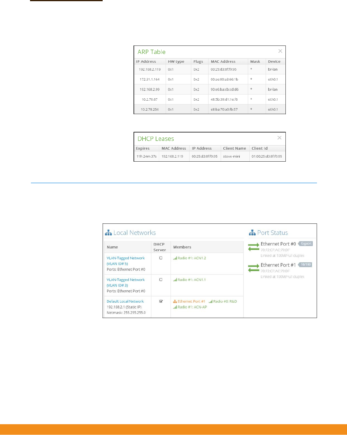
Options
—IncludesshowingtheARPcache,showingDHCPleases,or
renewingDHCPleases.
Figure12:Options
–
24
–
Chapter2
|
StatusInformation
LocalNetworks
Figure13:ARPTable
Figure14:DHCPLeases
LocalNetworks
TheLocalNetworkssectionshowsinformationaboutthelocalnetworkconnection.
Figure15:LocalNetworks
Thefollowingitemsaredisplayedinthissection:
◆
Name
—Showsinformationonthenameofthelocalnetwork,whetherstatic
ordynamicconfigurationisused,andthenetworkmask.
◆
DHCPServer
—ShowsifDHCPserviceisenabledonthisnetwork.
◆
Members—Showstheportsandwirelessradiosattachedtothisnetwork.
◆
PortStatus
—ShowsthestatusoftheEthernetports,includinglinkupstate,
MACaddress,speed,andduplexmode.
–
25
–
Chapter2
|
StatusInformation
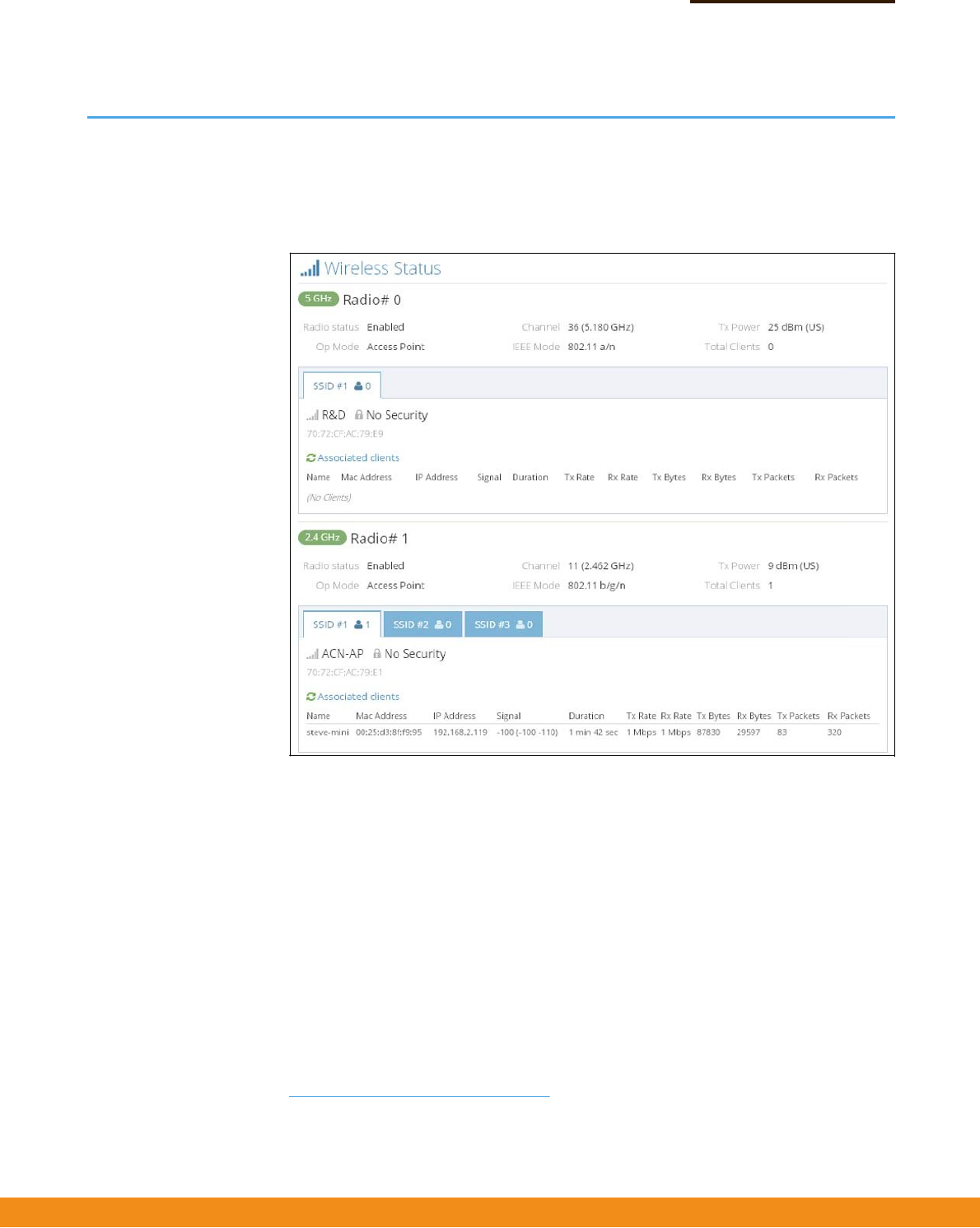
WirelessStatus
WirelessStatus
TheWirelessStatussectionshowsinformationabouttheradiosettingsand
associatedclients.
Figure16:WirelessStatus
Thefollowingitemsaredisplayedinthissection:
◆
Radio#
—Indicatesthe5GHzor2.4GHzwirelessinterface.
■
RadioStatus—Showsifthewirelessinterfaceisenabledordisabled.
■
OpMode—Showsiftheunitisconfiguredtooperateasanaccesspoint
(manuallyconfigured),anAPinbridgemode,oranAPinroutermode.
■
Channel—Theradiochanneltheaccesspointusestocommunicatewith
wirelessclients.Theavailablechannelsdependonthe802.11Mode
1
,
ChannelBandwidth
1
,andCountryCodesettings
2
.
■
IEEEMode—The802.11wirelessLANstandardssupportedbytheaccess
point.
1.
See“RadioSettings”onpage37.
2.
See“SetupWizard”onpage15.

–
26
–
Chapter2
|
StatusInformation
WirelessStatus
■
TxPower—Thepoweroftheradiosignalstransmittedfromtheaccess
point.
■
TotalClients—Thetotalnumberofclientsattachedtothisinterface.
◆
SSID#—Servicesetidentifier.Clientsthatwanttoconnecttothewireless
networkthroughanaccesspointmustsettheirSSIDstothesameasthatofthe
accesspoint.
■
NetworkName—Auniqueidentifierforthelocalwirelessnetwork.
■
Security—Showswhetherornotsecurityhasbeenenabled.
■
Associatedclients—Showsdetailedinformationaboutclients.
■
Name—Clientname.
■
MACAddress—TheMACaddressofthewirelessclient.
■
IPAddress—TheIPaddressassignedtothewirelessclient.
■
Signal—Signalstrength(TX/RX)indBm.
■
Duration—Thetimethewirelessclienthasbeenassociated.
■
TxRate—Thedatatransmitratetothewirelessclient.
■
RxRate—Thedatareceiveratefromthewirelessclient.
■
TxBytes—Thenumberoftransmittedbytestothisclient.
■
RxBytes—Thenumberofreceivedbytesfromthisclient
■
TxPackets—Thenumberoftransmittedpacketstothisclient.
■
RxPackets—Thenumberofreceivedpacketsfromthisclient.
–
27
–
Chapter2
|
StatusInformation
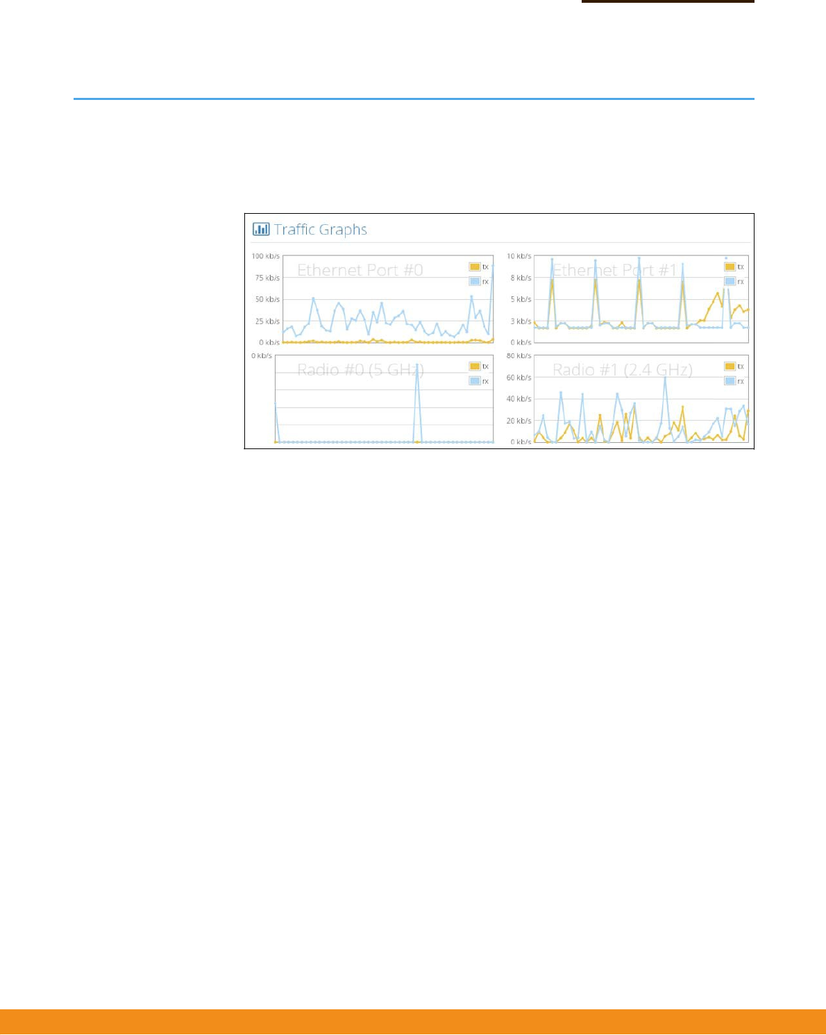
TrafficGraphs
TrafficGraphs
TheTrafficGraphssectionshowsthedataratefortheEthernetportsandwireless
interfaces.
Figure17:TrafficGraphs
–
28
–
NetworkSettings
Thischapterdescribesbasicnetworksettingsontheaccesspoint.Itincludesthe
followingsections:
◆
“InternetSettings”onpage28
◆
“EthernetSettings”onpage31
◆
“LANSettings”onpage33
◆
“HotspotSettings”onpage34
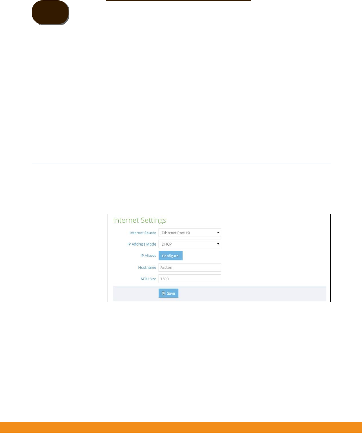
InternetSettings
TheInternetSettingspageconfiguresthebasicInternetsettingsfortheAP,suchas
thesourceport,IPaliases,aswellasthehostnameandmaximumMTUsize.
Figure18:InternetSettings
Thefollowingitemsaredisplayedonthispage:
◆
InternetSource—TheEthernetportusedtoaccesstheInternet.
(Default:EthernetPort0;Options:EthernetPort0‐1)
◆
IPAddressMode—ThemethodusedtoprovideanIPaddressfortheInternet
accessport.(Default:DHCP;Options:DHCP,staticIP,PPPoE)
■
DHCP
—ConfigurationoptionsdisplayedforDHCPareshowninFigure18,
“InternetSettings",onpage28.
3
–
29
–
Chapter3
|
NetworkSettings
InternetSettings
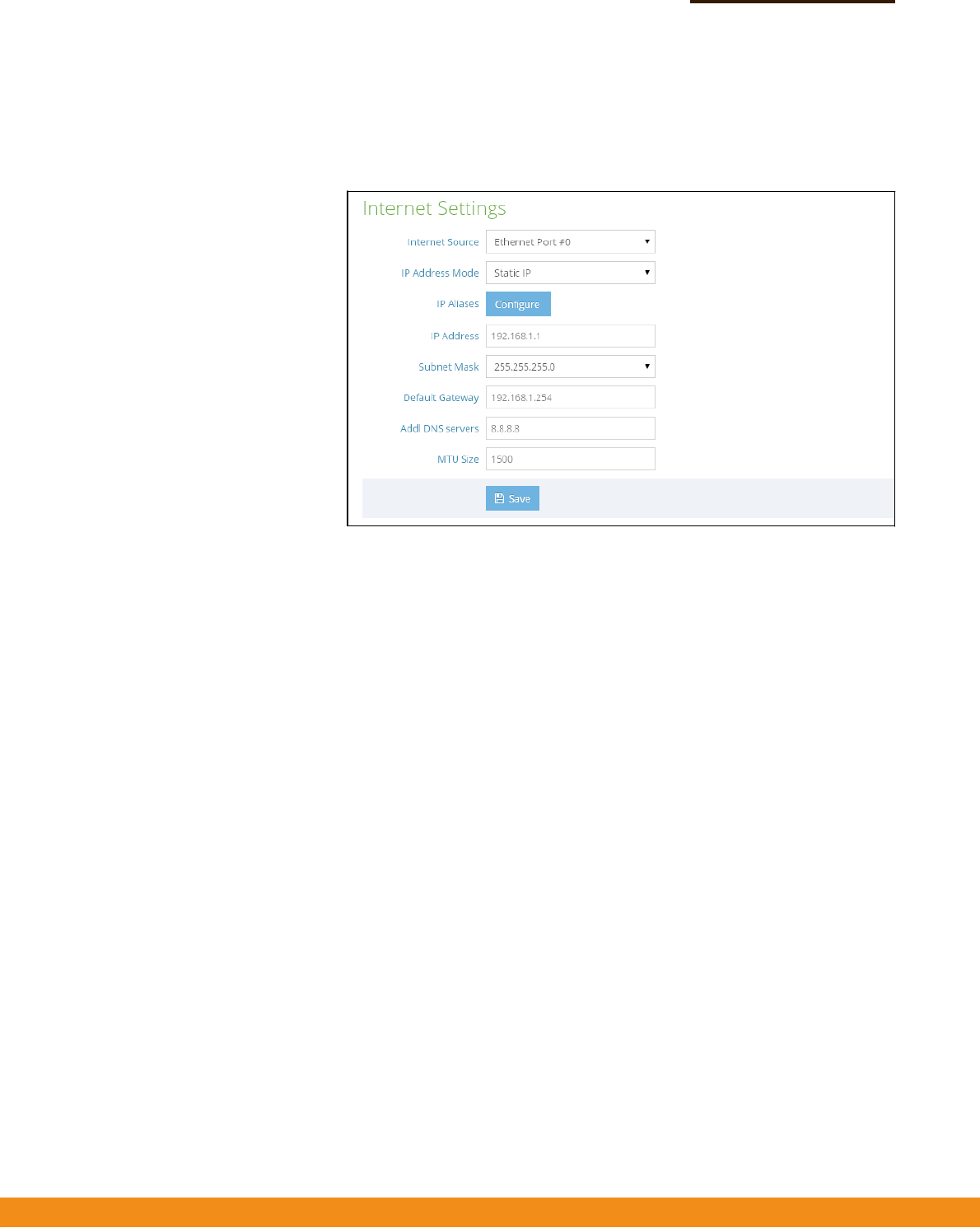
■
StaticIP—ToconfigureastaticIPaddressfortheselectedEthernet
interface,thefollowingitemsmustbespecified.
Figure19:IPAddressMode–StaticIP
■
IPAddress—SpecifiesanIPaddressfortheaccesspoint.ValidIP
addressesconsistoffourdecimalnumbers,0to255,separatedby
periods.(Default:192.168.1)
■
SubnetMask—Indicatesthelocalsubnetmask.
(Default:255.255.255.0)
■
DefaultGateway—TheIPaddressofthedefaultgateway,whichis
usediftherequesteddestinationaddressisnotonthelocalsubnet.
Ifyouhavemanagementstations,DNS,RADIUS,orothernetwork
serverslocatedonanothersubnet,typetheIPaddressofthedefault
gatewayrouterinthetextfieldprovided.
■
AddlDNSServer—TheIPaddressofDomainNameServersonthe
network.ADNSmapsnumericalIPaddressestodomainnamesand
canbeusedtoidentifynetworkhostsbyfamiliarnamesinsteadofthe
IPaddresses.
IfyouhaveaDNSserverslocatedonthelocalnetwork,typetheIP
addressinthetextfieldsprovided.
–
30
–
Chapter3
|
NetworkSettings
InternetSettings
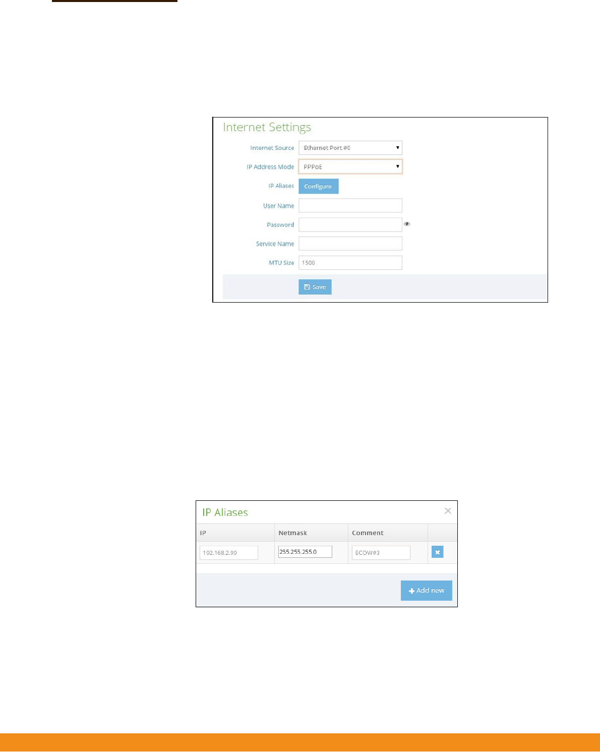
■
PPPoE—ToobtainanIPaddressfortheselectedEthernetinterfaceusing
PPPoE,thefollowingitemsmustbespecified.
Figure20:IPAddressMode–PPPoE
■
UserName—Theusernamespecifiedbytheserviceprovider.
(Range:1‐32characters)
■
Password—Thepasswordspecifiedbytheserviceprovider.
(Range:1‐32characters)
■
ServiceName
—TheservicenameassignedforthePPPoEconnection.
Theservicenameisnormallyoptional,butmayberequiredbysome
serviceproviders.(Range:1‐32alphanumericcharacters)
◆
IPAliases—AddsastaticIPv4addressunderwhichtheaccesspointcanalso
bereached.
Figure21:IPAlias
◆
MTUSize—Setsthesizeofthemaximumtransmissionunit(MTU)forpackets
sentonthisinterface.(Range:1400‐1500bytes;Default1500bytes)
–
31
–
Chapter3
|
NetworkSettings
EthernetSettings
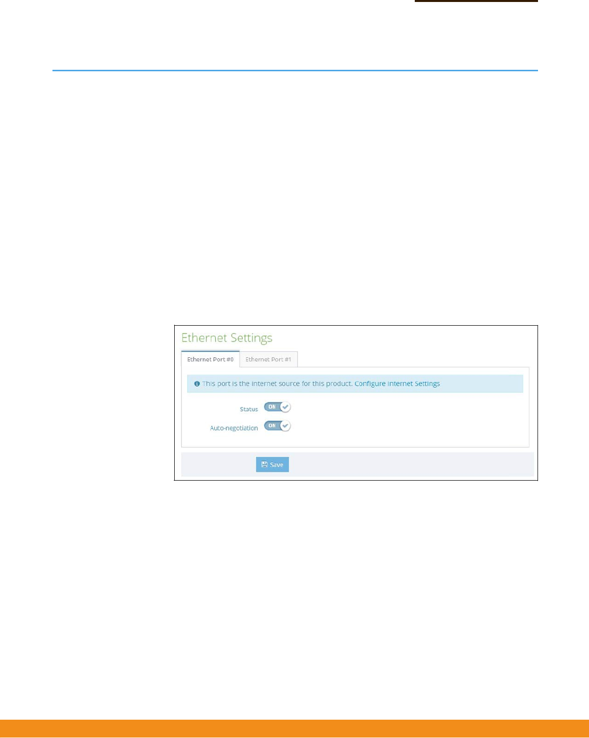
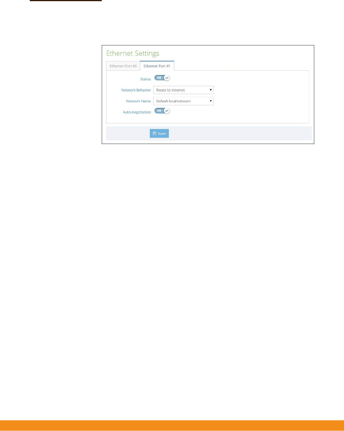
EthernetSettings
TheEthernetSettingspageconfiguresthenetworkbehavioroftheEthernetports,
indicatingthataportprovidesanInternetconnectionforwirelessclientsattached
tothelocalnetwork(routedtotheInternet),isbridgeddirectlytotheInternet,
connectedtotheguestnetwork,orprovideshotspotservice.
ThefollowingitemsarecommonforallpagesunderEthernetSettings:
◆
Status
—Enablesordisablesthisport.(Default:ON)
◆
Auto‐negotiation—Enablesordisablesauto‐negotiationforagiven
interface.(Default:ON)
1000BASE‐Tdoesnotsupportforcedmode.Auto‐negotiationshouldalwaysbe
usedtoestablishaconnectionoverany1000BASE‐Tport.
Whenauto‐negotiationisenabled,theaccesspointwillnegotiatethebest
settingsforalinkbasedonadvertisedcapabilities.
Figure22:EthernetSettings–InternetSource
Thefollowingstatusmessageisdisplayedifaninterfaceisconnectedtothe
Internet:
◆
“Thisportistheinternetsourceforthisproduct.ConfigureInternetSettings”
IfmorethanoneinterfaceisconnectedtotheInternet,onlythelastconfigured
interfaceisused.
–
32
–
Chapter3
|
NetworkSettings
EthernetSettings
Figure23:EthernetSettings–NetworkBehavior
Thefollowingitemsaredisplayedonthispage:
◆
NetworkBehavior
—FortheEthernetportwhichisnotprovidingInternet
access,oneofthefollowingconnectionmethodsmustbespecified.
(Default:RoutetoInternet)
■
BridgetoInternet
—ConfiguresaninterfacetobeattachedtotheWAN.
TrafficfromthisinterfaceisdirectlybridgedintotheInternet.(SeeFigure6,
“BridgetoInternet",onpage17.)IfanEthernetportisbridgedtothe
Internet,managementaccesscannotbemadebyadirectconnectionto
thisport.However,ifanotherEthernetportorradiointerfaceiswithinthe
LAN(routedtotheInternet)theaccesspointcanbemanagedthroughthis
interfacebyaPCwhichisconfiguredwithIPaddressinthesamesubnet.
■
RoutetoInternet
—ConfiguresaninterfacetobeamemberoftheLAN.
Trafficfromthisinterfaceisroutedacrosstheaccesspointandoutthrough
aninterfacewhichisbridgedtotheInternet.(SeeFigure7,“Routeto
Internet",onpage18.)Bydefault,EthernetPort1isroutedtoInternet,
allowingmanagementaccessviaadirectconnectiontoaPCconfigured
withanaddressinthesamesubnet.
■
NetworkName
—Thenetworktoberouted.Thedefaultis“Default
localnetwork”asdisplayedunderLANSettings–LocalNetworks.
■
AddtoGuestNetwork
—Thisportcanonlyaccesstheguestnetwork.
■
HotspotControlled
—Thisportcanonlyaccesshotspotservices.
■
ConfigureHotspot
—OpenstheHotspotSettingspage.
–
33
–
Chapter3
|
NetworkSettings
LANSettings
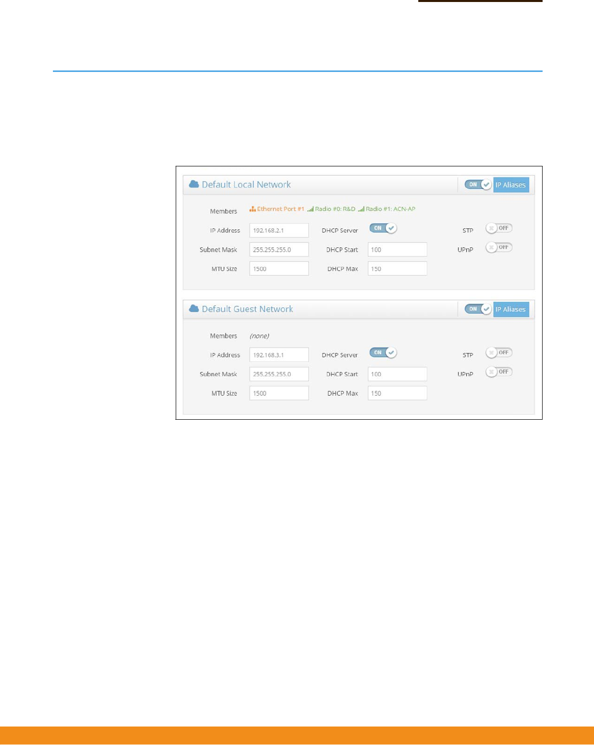
LANSettings
TheLANSettingspageconfigurestheLANsettingsforthelocalnetworkandguest
network,includingIPinterfacesetting,DHCPserversettings,STPadministrative
status,andUPnPadministrativestatus.
Figure24:Network–LANSettings
Thefollowingitemsaredisplayedonthispage:
◆
Members—Theinterfacesattachedtothelocalareanetwork.
◆
IPAddress—SpecifiestheIPaddressforthelocalnetworkorguestnetwork.
ValidIPaddressesconsistoffourdecimalnumbers,0to255,separatedby
periods.(Default:192.168.2.1)
◆
SubnetMask—Indicatesthelocalsubnetmask.(Default:255.255.255.0)
◆
MTUSize—Setsthesizeofthemaximumtransmissionunit(MTU)forpackets
sentonthisnetwork.
◆
DHCPServer
—Enables/disablesDHCPonthisnetwork.(Default:Enabled)
■
DHCPStart—Firstaddressintheaddresspool.(Range:1‐256;
Default:x.x.x.100)
■
DHCPMax—Maximumnumberofaddressesintheaddresspool.
(Range:1‐255;Default:150)
–
34
–
Chapter3
|
NetworkSettings
HotspotSettings
◆
STP
—EnablesordisablesprocessingofSpanningTreeProtocolmessages.
(Default:Disabled)
◆
UPnP
—EnablesordisablesUniversalPlug‐and‐Playbroadcastmessages.
(Default:Disabled)
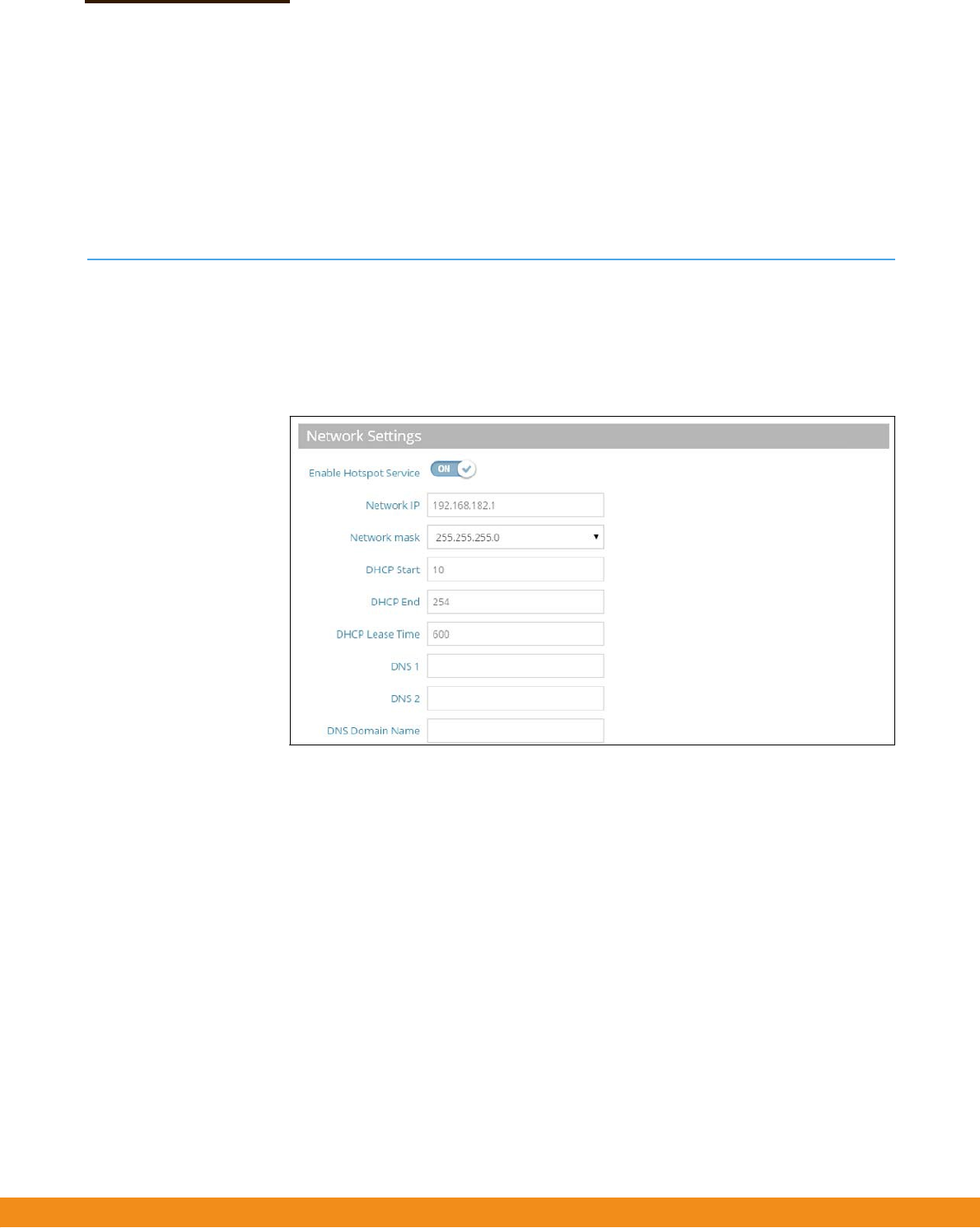
HotspotSettings
TheHotspotSettingspagecanconfigureInternetaccesstothegeneralpublicin
placessuchascoffeehouses,librariesandhospitals.Specificaccessrightsmayalso
bedefinedthroughaRADIUSserver.
Figure25:HotspotSettings(NetworkSettings)
Thefollowingitemsaredisplayedonthispage:
◆
NetworkIP—SpecifiestheIPaddressforthehotspot.ValidIPaddresses
consistoffourdecimalnumbers,0to255,separatedbyperiods.(Default:
192.168.182.1)
◆
NetworkMask—NetworkmaskfortheassociatedIPsubnet.Thismask
identifiesthehostaddressbitsusedforroutingtospecificsubnets.
◆
DHCPStart
—Startingnumberof(lastnumericfield)inaddresspool.
(Range:1‐254;Default:10)
◆
DHCPEnd—Endingnumberof(lastnumericfield)inaddresspool.
(Range:1‐254;Default:254)
◆
DHCPLeaseTime—ThedurationthatanIPaddressisassignedtoaDHCP
client.(Range:600‐43200seconds;Default:600seconds)
–
35
–
Chapter3
|
NetworkSettings
HotspotSettings
◆
DNS1—TheIPaddressoftheprimaryDomainNameServeronthenetwork.A
DNSmapsnumericalIPaddressestodomainnamesandcanbeusedtoidentify
networkhostsbyfamiliarnamesinsteadoftheIPaddresses.
◆
DNS2
—ThesecondaryDNSserveravailabletoDHCPclients.
◆
DNSDomainName
—Thedomainnameusedtoresolveincompletehost
namesviatheDomainNameSystem.(Range:1‐32characters)
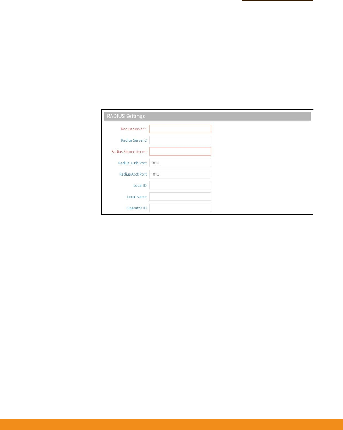
Figure26:HotspotSettings(RADIUSSettings)
Thefollowingitemsaredisplayedonthispage:
◆
RadiusServer1
—IPaddressorhostnameoftheprimaryRADIUSserver.
◆
RadiusServer2—IPaddressorhostnameofthesecondaryRADIUSserver.
◆
RadiusSharedSecret—Asharedtextstringusedtoencryptmessages
betweentheaccesspointandtheRADIUSserver.Besurethatthesametext
stringisspecifiedontheRADIUSserver.Donotuseblankspacesinthestring.
(Range:1‐255characters).
◆
RadiusAuthPort—RADIUSserverUDPportusedforauthentication
messages.(Range:1‐65535,Default:1812)
◆
RadiusAcctPort
—RADIUSserverUDPportusedforaccountingmessages.
(Range:1‐65535,Default:1813)
◆
LocalID
—LocalRADIUSserveridentifier.
◆
LocalName
—LocalRADIUSservername
◆
OperationID
—LocalRADIUSserveroperationidentifier.
–
36
–
Chapter3
|
NetworkSettings
HotspotSettings
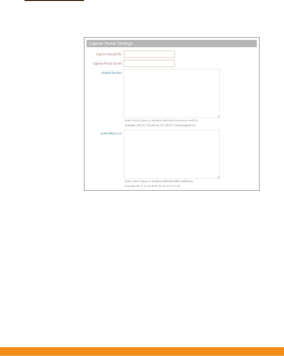
Figure27:HotspotSettings(CaptivePortalSettings)
Thefollowingitemsaredisplayedonthispage:
◆
CaptivePortalURL—HostnameofInternetserviceportalforthehotspot.
Thecaptiveportalforcesahotspotclienttoaccessawelcomewebpage(normally
usedforauthentication)beforegainingfurtheraccesstotheInternet.
The
welcomepagemayrequireauthenticationand/orpayment.
◆
CaptivePortalSecret
—Thepasswordusedforloggingintothehotspot.
◆
WalledGarden—Alistofwebsitestowhichunauthenticatedusersare
allowedtonavigate.
◆
AuthWhiteList—AlistofMACaddressesthatareallowedtobypassthe
captiveportaltoaccesstheinternet.

–
37
–
WirelessSettings
Thischapterdescribeswirelesssettingsontheaccesspoint.Itincludesthe
followingsections:
◆
“RadioSettings”onpage37
◆
“VLANSettings”onpage50
RadioSettings
TheIEEE802.11wirelessinterfacesincludeconfigurationoptionsforradiosignal
characteristicsandwirelesssecurityfeatures.
Theaccesspointcanoperateinseveralradiomodes,802.11a/a+n/AC(5GHz)or
802.11b+g/b+g+n(2.4GHz).Supportedmodesdependontheaccesspointmodel.
Notethatthedual‐bandaccesspointscanoperateat2.4GHzand5GHzatthe
sametime.Thewebinterfaceidentifiestheradioconfigurationpagesas:
◆
Radio0—the5GHz802.11a/n/ACradiointerface
◆
Radio1—the2.4GHz802.11b/g/nradiointerface
Eachradiosupports8virtualaccesspoint(VAP)interfacesbasedontheSSIDs,
referredtoasVAP0~VAP7.EachVAPfunctionsasaseparateaccesspoint,andcan
beconfiguredwithitsownServiceSetIdentification(SSID)andsecuritysettings.
However,mostradiosignalparametersapplytoallVAPinterfaces.Traffictospecific
VAPscanbesegregatedbasedonusergroupsorapplicationtraffic.Theclients
associatewitheachVAPinthesamewayastheywouldwithseparatephysical
accesspoints.TheAPsupportsuptoatotalof127wirelessclientsacrossallVAP
interfacesperradio.
4
–
38
–
Chapter4
|
WirelessSettings
RadioSettings
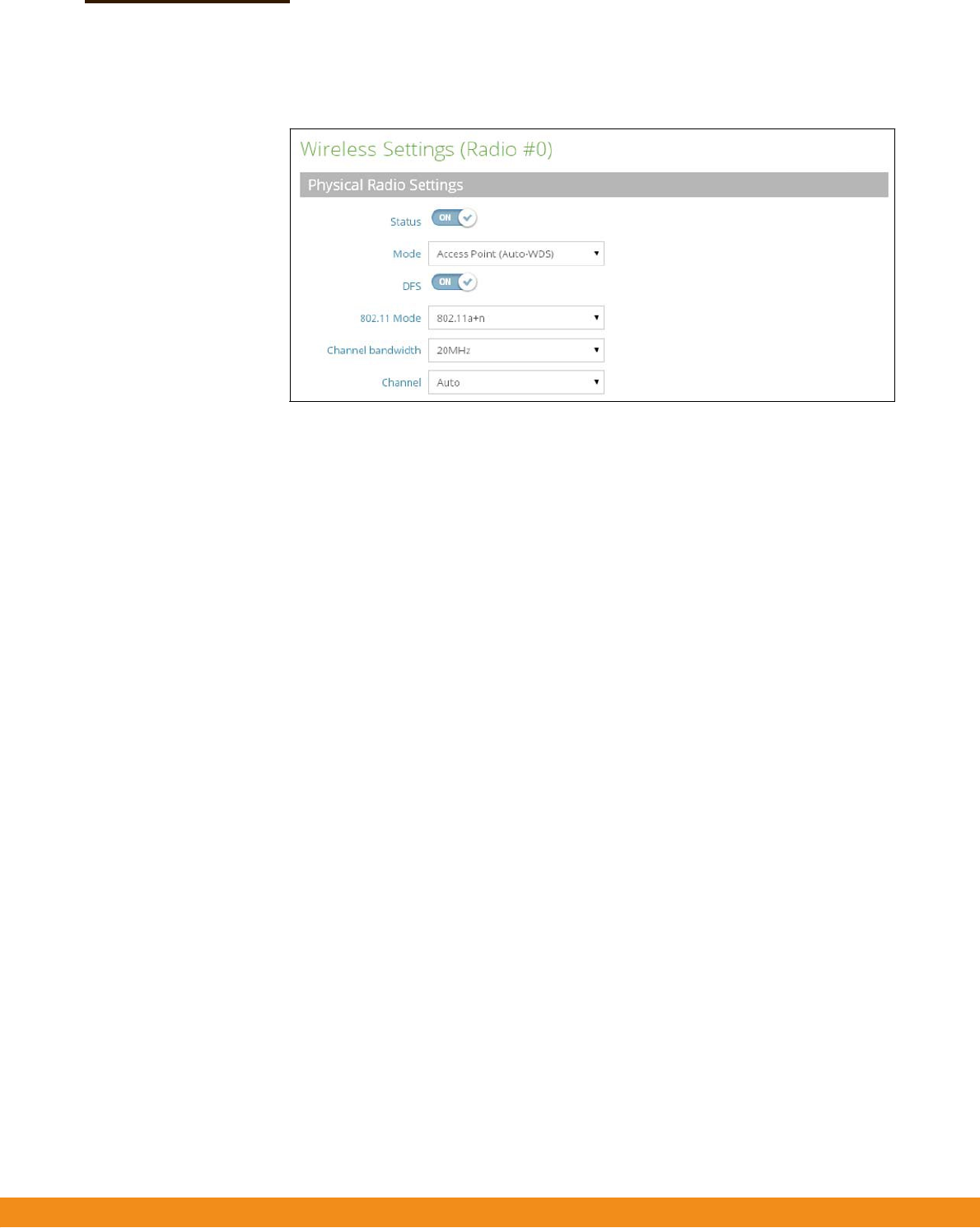
Figure28:RadioSettings(PhysicalRadioSettings)
Thefollowingitemsaredisplayedonthispage:
◆
Status
—Enablesordisablesthewirelessserviceonthisinterface.
◆
Mode—SelectsthemodeinwhichtheAPwillfunction.
■
AccessPoint(Auto‐WDS)
—TheVAPoperatesasanaccesspointinWDS
mode,whichacceptsconnectionsfromAPsinClientWDSmode.(Thisis
thedefaultsetting.)
Inthismode,theAPprovidesservicestoclientsasanormalaccesspoint.
WDSisusedtoautomaticallysearchforandconnecttootherAPnodes
usingthesameSSIDandsecuritysettings.
■
Client—TheAPcanprovideawirelessconnectiontoanotherAP.Inthis
mode,itcanpassinformationfromortolocallywiredhosts,butdoesnot
provideservicestoanywirelessclients.
■
ClientWDS—TheAPprovidesservicestoclientsasanormalaccesspoint,
andoperatesasaclientstationinWDSmode,whichcanconnecttoother
accesspointsinAuto‐WDSmode.ConnectiontoanotherAPcanbemade
automaticallybyotheraccesspointsoperatinginAuto‐WDSmode.
◆
DFS—DynamicFrequencySelectioncanbeusedtodetectandavoid
interferencewithRadarsystemsoperatinginthe5GHzrange(UNIIchannels
52‐64and100‐140).Ifradarisdetected,theAPwillalterthechannelitis
operatingonandtellassociatedstationsthechanneltowhichitismoving.This
allowsstationstore‐associatewithminimuminterruption.(Thisparameteris
onlyapplicabletothe5GHzradio,andisenabledbydefault.)
◆
802.11Mode
—Definestheradiooperationmode.
■
Radio0(5GHzRadio)—Default:11a+n;Options:11a,11a+n,11AC
■
Radio1
(2.4GHzRadio)—Default:11b+g;Options:11b+g,11b+g+n

–
39
–
Radio 0(5 GHz) Radio 1(2.4GHz)
Chapter4
|
WirelessSettings
RadioSettings
◆
ChannelBandwidth
—TheAPoptionsforchannelbandwidthinclude5,10,
20,40and80MHz.Using20MHzgivesan802.11gconnectionaspeedof
54Mbpsandan802.11nconnectionaspeedofupto108Mbps,andensures
backwardcomplianceforslower802.11bdevices.Settingthechannel
bandwidth
to40MHzprovidesaconnectionspeedfor802.11nofupto300Mbps.Usinga
channelbandwidthof80MHzprovidesaconnectionspeedupto
866.7Mbps.(Default:20MHz;Range:5MHz,10MHz,20MHz,40MHz,80MHz)
◆
Channel—Theradiochannelthattheaccesspointusestocommunicatewith
wirelessclients.Whenmultipleaccesspointsaredeployedinthesamearea,set
thechannelonneighboringaccesspointsatleastfivechannelsaparttoavoid
interferencewitheachother.Forexample,for11g/n20MHzmodeyoucan
deployuptothreeaccesspointsinthesameareausingchannels1,6,11.Note
thatwirelessclientsautomaticallysetthechanneltothesameasthatusedby
theaccesspointtowhichitislinked.(Theavailablechannelsaredependenton
the802.11Mode,ChannelBandwidth,andCountryCodesettings.)
SelectingAutoenablestheaccesspointtoautomaticallyselectanunoccupied
radiochannel.(Default:Auto)
Table1:RadioChannels
RadioChannels
a
Frequency(GHz)
RadioChannels Frequency(GHz)
Auto
Autoscan
Auto
Autoscan
365.18012.412
405.20022.417
445.22032.422
485.24042.427
1495.74552.432
1535.76562.437
1575.78572.422
1615.80582.447
1655.82592.452
102.457
112.462
a.Supportedchannelsdependonthe802.11modeandchannelbandwidth.
–
40
–
Chapter4
|
WirelessSettings
RadioSettings
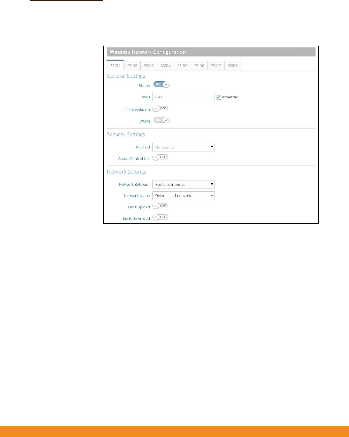
Figure29:RadioSettings(WirelessNetworkConfiguration)
Thefollowingitemsaredisplayedonthispage:
GeneralSettings
◆
Status
—EnablesordisablesthewirelessserviceonthisVAP.
◆
SSID—ThenameofthebasicservicesetprovidedbyaVirtualAccessPoint
(VAP)interface.Clientsthatwanttoconnecttothenetworkthroughtheaccess
pointmustsettheirSSIDtothesameasthatoftheaccesspoint’sVAPinterface.
(Default:ACN0.#(where#is0‐7)for5GHz,ACN1.#(where#is0‐7)for2.4GHz;
Range:1‐32characters)
◆
Broadcast
—TheSSIDcanbebroadcastatregularintervalssothatwireless
stationssearchingforanetworkconnectioncandiscoverit.Thisallowswireless
clientstodynamicallydiscoverandroambetweenWLANs.Thisfeaturealso
makesiteasierforhackerstobreakintoyourhomenetwork.BecauseSSIDsare
notencrypted,itiseasytograbonebysnoopingtheWLANlookingforSSID
broadcastmessagescomingfromtheAP.(Default:Enabled)
◆
ClientIsolation
—Ifenabled,wirelessclientscantalktotheLAN,andreach
theInternetifsuchconnectionisavailable,buttheycannotcommunicatewith
oneanother.(DefaultDisabled)

–
41
–
Chapter4
|
WirelessSettings
RadioSettings
◆
WMM—SetstheWMMoperationalmodeontheaccesspoint.Whenenabled,
theparametersforeachAccessCategory(AC)queuewillbeemployedonthe
accesspointandQoScapabilitiesadvertisedtoWMM‐enabledclients.
(Default:
Enabled)
Whenenabled,WMMmustbesupportedonanydevicetryingtoassociated
with
theaccesspoint.Devicesthatdonotsupportthisfeaturewillnotbe
allowedto
associatewiththeaccesspoint.
Wirelessnetworksofferanequalopportunityforalldevicestotransmitdata
fromanytypeofapplication.Althoughthisisacceptableformostapplications,
multimediaapplications(withaudioandvideodata)areparticularlysensitive
tothedelayandthroughputvariationsthatresultfromthis“equalopportunity”
wirelessaccessmethod.Formultimediaapplicationstorunwelloverawireless
network,aQualityofService(QoS)mechanismisrequiredtoprioritizetraffic
typesandprovidean“enhancedopportunity”wirelessaccessmethod.
TheaccesspointimplementsQoSusingtheWi‐FiMultimedia(WMM)standard.
UsingWMM,theaccesspointisabletoprioritizetrafficandoptimize
performancewhenmultipleapplicationscompeteforwirelessnetwork
bandwidthatthesametime.WMMemploystechniquesthatareasubsetofthe
IEEE802.11eQoSstandardanditenablestheaccesspointtointer‐operatewith
bothWMM‐enabledclientsandotherdevicesthatmaylackanyWMM
functionality.
AccessCategories—WMMdefinesfouraccesscategories(ACs):voice,video,
besteffort,andbackground.Thesecategoriescorrespondtotrafficpriority
levelsandaremappedtoIEEE802.1Dprioritytags(seeFigure2,“WMMAccess
Categories",onpage41).ThedirectmappingofthefourACsto802.1D
prioritiesisspecificallyintendedtofacilitateinteroperabilitywithotherwired
networkQoSpolicies.WhilethefourACsarespecifiedforspecifictypesof
traffic,WMMallowstheprioritylevelstobeconfiguredtomatchanynetwork‐
wideQoSpolicy.WMMalsospecifiesaprotocolthataccesspointscanuseto
communicatetheconfiguredtrafficprioritylevelstoQoS‐enabledwireless
clients.
Table2:WMMAccessCategories
AC_VO(AC3)VoiceHighestpriority,minimumdelay.Time‐sensitive
datasuchasVoIP(VoiceoverIP)calls.
AC_VI(AC2)VideoHighpriority,minimumdelay.Time‐sensitivedata
suchasstreamingvideo.
7,6
5,4
AC_BE(AC0)BestEffortNormalpriority,mediumdelayandthroughput.
Dataonlyaffectedbylongdelays.Datafrom
applicationsordevicesthatlackQoScapabilities.
AC_BK(AC1)
Background
Lowestpriority.Datawithnodelayorthroughput
requirements,suchasbulkdatatransfers.
0,3
2,1
Access
Category
WMM
Description
Designation
802.1D
Tags
–
42
–
Chapter4
|
WirelessSettings
RadioSettings
WMMOperation—WMMusestrafficprioritybasedonthefourACs;Voice,
Video,
BestEffort,andBackground.ThehighertheACpriority,thehighertheprobability
thatdataistransmitted.
Whentheaccesspointforwardstraffic,WMMaddsdatapacketstofour
independenttransmitqueues,oneforeachAC,dependingonthe802.1Dpriority
tagofthepacket.Datapacketswithoutaprioritytagarealwaysadded
totheBest
EffortACqueue.Fromthefourqueues,aninternal“virtual”collision
resolution
mechanismfirstselectsdatawiththehighestprioritytobegrantedatransmit
opportunity.Thenthesamecollisionresolutionmechanismisused
externallyto
determinewhichdevicehasaccesstothewirelessmedium.
ForeachACqueue,thecollisionresolutionmechanismisdependentontwo
timingparameters:
◆AIFSN(ArbitrationInter‐FrameSpaceNumber),anumberusedto
calculatetheminimumtimebetweendataframes
◆CW(ContentionWindow),anumberusedtocalculatearandombackofftime
Afteracollisiondetection,abackoffwaittimeiscalculated.Thetotalwaittimeis
thesumofaminimumwaittime(ArbitrationInter‐FrameSpace,orAIFS)
determinedfromtheAIFSN,andarandombackofftimecalculatedfromavalue
selectedfromzerototheCW.TheCWvaluevarieswithinaconfigurablerange.
It
startsatCWMinanddoublesaftereverycollisionuptoamaximumvalue,
CWMax.
Afterasuccessfultransmission,theCWvalueisresettoitsCWMin
value.
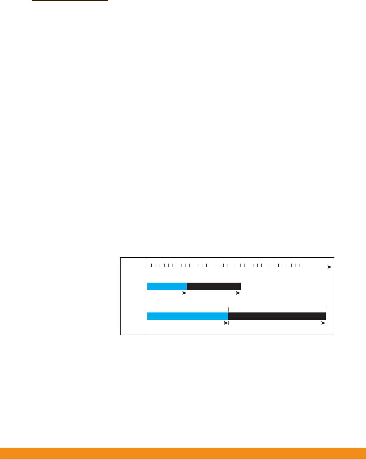
Figure30:WMMBackoffWaitTimes
Forhigh‐prioritytraffic,theAIFSNandCWvaluesaresmaller.Thesmallervalues
equatetolessbackoffandwaittime,andthereforemoretransmit
opportunities.
High Priority
Low Priority
Time
CWMin CWMax
A
IFS
Random Backof
f
Minimum Wait Time Random Wait Time
CWMin CWMax
A
IFS
Random Backof
f
Minimum Wait Time Random Wait Time

–
43
–
Chapter4
|
WirelessSettings
RadioSettings
SecuritySettings
◆
Method—SetsthewirelesssecuritymethodforeachVAP,including
associationmode,encryption,andauthentication.(Default:NoSecurity)
■
NoSecurity—TheVAPbroadcastsabeaconsignalincludingthe
configuredSSID.WirelessclientswithanSSIDsettingof“any”canreadthe
SSIDfromthebeaconandautomaticallysettheirSSIDtoallowimmediate
connection.
■
WEPOpenSystem—TheVAPbroadcastsabeaconsignalincludingthe
configuredSSID.WirelessclientswithanSSIDsettingof“any”canreadthe
SSIDfromthebeaconandautomaticallysettheirSSIDtoallowimmediate
connection.
■
Key—WEPisusedtoencryptdatatransmittedbetweenwireless
clientsandtheVAP.WEPusesstaticsharedkeys(fixed‐length
hexadecimaloralphanumericstrings)thataremanuallydistributedto
allclientsthatwanttousethenetwork.
WEPisthesecurityprotocolinitiallyspecifiedintheIEEE802.11
standardforwirelesscommunications.Unfortunately,WEPhasbeen
foundtobeseriouslyflawedandcannotberecommendedforahigh
levelofnetworksecurity.Formorerobustwirelesssecurity,theaccess
pointprovidesWi‐FiProtectedAccess(WPA)andWPA2forimproved
dataencryptionanduserauthentication.
BesurethattheWEPsharedkeysarethesameforeachclientinthe
wirelessnetwork.Allclientssharethesamekeys,whichareusedfor
dataencryption.
For64‐bitWEP,stringlengthmustbe5ASCIIcharacters(lettersand
numbers)or10hexadecimaldigits.For128‐bitWEP,stringlengthmust
be13ASCIIcharacters(lettersandnumbers)or26hexadecimaldigits.
■
WPA‐PSK—Forenterprisedeployment,WPArequiresaRADIUS
authenticationservertobeconfiguredonthewirednetwork.However,for
smallofficenetworksthatmaynothavetheresourcestoconfigureand
maintainaRADIUSserver,WPAprovidesasimpleoperatingmodethatuses
justapre‐sharedpasswordfornetworkaccess.ThePre‐SharedKeymode
usesacommonpasswordforuserauthenticationthatismanuallyentered
ontheaccesspointandallwirelessclients.ThePSKmodeusesthesame
TKIPpacketencryptionandkeymanagementasWPAintheenterprise,
providingarobustandmanageablealternativeforsmallnetworks.
■
Encryption
—Dataencryptionusesoneofthefollowingmethods:
■
CCMP(AES)—AES‐CCMPisusedasthemulticastencryption
cipher.AES‐CCMPisthestandardencryptioncipherrequiredfor
WPA2.(Thisisthedefaultsetting.)
■
TKIP
—TKIPisusedasthemulticastencryptioncipher.

–
44
–
Chapter4
|
WirelessSettings
RadioSettings
■
Auto:TKIP+CCMP(AES)
—Theencryptionmethodusedbythe
clientisdiscoveredbytheaccesspoint.
■
Key—WPAisusedtoencryptdatatransmittedbetweenwireless
clientsandtheVAP.WPAusesstaticsharedkeys(fixed‐length
hexadecimaloralphanumericstrings)thataremanuallydistributedto
allclientsthatwanttousethenetwork.
Stringlengthmustbe8to63ASCIIcharacters(lettersandnumbers).
Nospecialcharactersareallowed.
■
WPA2‐PSK:ClientsusingWPA2withaPre‐sharedKeyareacceptedfor
authentication.
WPAwasintroducedasaninterimsolutionforthevulnerabilityofWEP
pendingtheratificationoftheIEEE802.11iwirelesssecuritystandard.In
effect,theWPAsecurityfeaturesareasubsetofthe802.11istandard.WPA2
includesthenowratified802.11istandard,butalsooffersbackward
compatibilitywithWPA.Therefore,WPA2includesthesame802.1XandPSK
modesofoperationandsupportforTKIPencryption.
RefertoWPA‐PSKforadescriptionofencryptionmethodsandthekey.
■
WPA‐EAP—WPAemploysacombinationofseveraltechnologiesto
provideanenhancedsecuritysolutionfor802.11wirelessnetworks.A
RADIUSserverisusedforauthentication,andcanalsobeusedfor
accounting.
RefertoWPA‐PSKforadescriptionofencryptionmethods.
RADIUSSettings
ARADIUSservermustbespecifiedfortheaccesspointtoimplementIEEE
802.1XnetworkaccesscontrolandWi‐FiProtectedAccess(WPA)wireless
security.
Inaddition,youcanconfigureaRADIUSAccountingservertoreceiveuser‐
sessionaccountinginformationfromtheaccesspoint.RADIUSAccounting
canbeusedtoprovidevaluableinformationonuseractivityinthe
network.
ThisguideassumesthatyouhavealreadyconfiguredRADIUSserver(s)tosupport
theaccesspoint.ConfigurationofRADIUSserversoftwareisbeyondthescopeof
thisguide,refertothedocumentationprovidedwiththeRADIUSserversoftware.
■
RadiusAuthServer
—SpecifiestheIPaddressorhostnameofthe
RADIUSauthenticationserver.
■
RadiusAuthPort—TheUDPportnumberusedbytheRADIUSserver
forauthenticationmessages.(Range:1024‐65535;Default:1812)

–
45
–
Chapter4
|
WirelessSettings
RadioSettings
■
RadiusAuthSecret—Asharedtextstringusedtoencryptmessages
betweentheaccesspointandtheRADIUSserver.Besurethatthesame
textstringisspecifiedontheRADIUSauthenticationserver.Donotuse
blankspacesinthestring.(Maximumlength:255characters)
■
RadiusAcctServer
—SpecifiestheIPaddressorhostnameofthe
RADIUSaccountingserver.
■
RadiusAcctPort
—TheUDPportnumberusedbytheRADIUSserver
foraccountingmessages.(Range:1024‐65535;Default:1813)
■
RadiusAcctSecret—Asharedtextstringusedtoencryptmessages
betweentheaccesspointandtheRADIUSserver.Besurethatthesame
textstringisspecifiedontheRADIUSaccountingserver.Donotuse
blankspacesinthestring.(Maximumlength:255characters)
■
WPA2‐EAP—WPAwasintroducedasaninterimsolutionforthe
vulnerabilityofWEPpendingtheratificationoftheIEEE802.11iwireless
securitystandard.Ineffect,theWPAsecurityfeaturesareasubsetofthe
802.11istandard.WPA2includesthenowratified802.11istandard,butalso
offersbackwardcompatibilitywithWPA.Therefore,WPA2includesthe
same802.1XandPSKmodesofoperationandsupportforTKIPencryption.
ARADIUSserverisusedforauthentication,andcanalsobeusedto
accounting.
RefertoWPA‐PSKforadescriptionofencryptionmethods.
RefertoWPA‐EAPforainformationonconfiguringtheRADIUSserver.
◆
AccessControlList—Wirelessclientscanbeauthenticatedfornetworkaccess
bycheckingtheirMACaddressagainstthelocaldatabaseconfiguredonthe
accesspoint.(Default:OFF)
■
Policy
—TheMAClistcanbeconfiguredtoeitherallowordenynetwork
accesstospecifiedclients.(Default:AllowallMACsonlist)
■
FilteredMACs—Enteraphysicaladdressforeachclient.Entersixpairsof
hexadecimaldigitsseparatedbycolons,andfollowedbyanoptional
comment;forexample,00:90:D1:12:AB:89JohnSmith’sPC
NetworkSettings
◆
NetworkBehavior
—Oneofthefollowingconnectionmethodsmustbe
specified.(Default:RoutetoInternet)
■
BridgetoInternet
—ConfiguresaninterfaceasattachedtotheWAN.
TrafficfromthisinterfaceisdirectlybridgedintotheInternet.(SeeFigure6,
“BridgetoInternet",onpage17.)

–
46
–
Chapter4
|
WirelessSettings
RadioSettings
■
RoutetoInternet
—ConfiguresaninterfaceasamemberoftheLAN.
Trafficfromthisinterfaceisroutedacrosstheaccesspointandoutthrough
aninterfacewhichisbridgedtotheInternet.(SeeFigure7,“Routeto
Internet",onpage18.)
■
NetworkName
—Thenetworktoberouted.Thedefaultis“Default
localnetwork”asdisplayedunderLANSettings–LocalNetwork.
■
AddtoGuestNetwork
—Thisinterfacecanonlysupporttheguest
network.
■
HotspotControlled
—Thisinterfacecanonlysupporthotspotservices.
■
ConfigureHotspot
—OpensHotspotSettingspage.
■
VLANTagTraffic
—TagsanypacketspassingfromthisVAP(virtualaccess
point)totheassociatedEthernetportasconfiguredunder“VLANSettings”
onpage50.(Range:3‐4095)
◆
LimitUpload—EnablesratelimitingoftrafficfromtheVAPinterfaceasitis
passedtothewirednetwork.YoucansetamaximumrateinKbytespersecond.
(Range:256‐10048576Kbytespersecond;Default:OFF)
◆
LimitDownload—Enablesratelimitingoftrafficfromthewirednetworkasit
ispassedtotheVAPinterface.Youcansetamaximumrateinkbytesper
second.(Range:256‐10048576Kbytespersecond;Default:OFF)
AdvancedSettings
◆
802.11Rates—TheminimumdatarateatwhichtheAPtransmitspacketson
thewirelessinterface.
Table3:802.11DataRates
Option
Rate(Max) CodingMethod
Radio0(5GHz)
Radio1(2.4GHz)
Auto
Auto
Basedonsignalstrength
√
√
1M1Mbps
CKK
√
2M2Mbps
CKK
√
5.5M5.5Mbps
CKK
√
11M11Mbps
CKK
√
√
6M6MbpsOFDM
√
√
9M9MbpsOFDM
√
√
12M12MbpsOFDM
√
√
18M18MbpsOFDM
√
√
24M24MbpsOFDM
√
√
36M36MbpsOFDM
√
√

–
47
–
Chapter4
|
WirelessSettings
RadioSettings
Table3:802.11DataRates(Continued)
Option
Rate(Max) CodingMethod
Radio0(5GHz)
Radio1(2.4GHz)
48M48MbpsOFDM
√
√
54M54MbpsOFDM
√
√
MCS015MbpsBPSK,singlestream
√
√
MCS130MbpsQPSK,singlestream
√
√
MCS245MbpsQPSK,singlestream
√
√
MCS360Mbps16‐QAM,singlestream
√
√
MCS490Mbps16‐QAM,singlestream
√
√
MCS5120Mbps64‐QAM,singlestream
√
√
MCS6135Mbps64‐QAM,singlestream
√
√
MCS7150Mbps64‐QAM,singlestream
√
√
MCS830MbpsBPSK,doublestream
√
√
MCS960MbpsQPSK,doublestream
√
√
MCS1090MbpsQPSK,doublestream
√
√
MCS11120Mbps16‐QAM,doublestream
√
√
MCS12180Mbps16‐QAM,doublestream
√
√
MCS13240Mbps64‐QAM,doublestream
√
√
MCS14270Mbps64‐QAM,doublestream
√
√
MCS15300Mbps64‐QAM,doublestream
√
√
NSS1‐MCS032.5Mbps256‐QAM,singlestream
√
NSS1‐MCS165Mbps256‐QAM,singlestream
√
NSS1‐MCS297.5Mbps256‐QAM,singlestream
√
NSS1‐MCS3130Mbps256‐QAM,singlestream
√
NSS1‐MCS4195Mbps256‐QAM,singlestream
√
NSS1‐MCS5260Mbps256‐QAM,singlestream
√
NSS1‐MCS6292.5Mbps 256‐QAM,singlestream
√
NSS1‐MCS7325Mbps256‐QAM,singlestream
√
NSS1‐MCS8390Mbps256‐QAM,singlestream
√
NSS1‐MCS9433.3Mbps 256‐QAM,singlestream
√
NSS2‐MCS065Mbps256‐QAM,doublestream
√
NSS2‐MCS1130Mbps256‐QAM,doublestream
√
NSS2‐MCS2195Mbps256‐QAM,doublestream
√
NSS2‐MCS3260Mbps256‐QAM,doublestream
√
NSS2‐MCS4390Mbps256‐QAM,doublestream
√

–
48
–
Chapter4
|
WirelessSettings
RadioSettings
Table3:802.11DataRates(Continued)
Option
Rate(Max) CodingMethod
Radio0(5GHz)Radio1(2.4GHz)
NSS2‐MCS5520Mbps256‐QAM,doublestream
√
NSS2‐MCS6585Mbps256‐QAM,doublestream
√
NSS2‐MCS7650Mbps256‐QAM,doublestream
√
NSS2‐MCS8780Mbps256‐QAM,doublestream
√
NSS2‐MCS9866.7Mbps 256‐QAM,doublestream
√
◆
TxStreams—Specifiesasinglestreamat20MHzoradualstreamat20MHz
and40MHzforsignaltransmission.(Options:1,2;Default1)
◆
RxStreams—Specifiesasinglestreamat20MHzoradualstreamat20MHz
and40MHzforsignalreception.(Options:1,2;Default1)
◆
TxPower—Adjuststhepoweroftheradiosignalstransmittedfromtheaccess
point.Thehigherthetransmissionpower,thefartherthetransmissionrange.
Powerselectionisnotjustatradeoffbetweencoverageareaandmaximum
supportedclients.Youalsohavetoensurethathigh‐powersignalsdonot
interferewiththeoperationofotherradiodevicesintheservicearea.
(Default:17dBmfor5GHzradio,27dBmfor2.4GHzradio)
Table4:TxPower
Power
Radio0(5GHz) Radio1(2.4GHz)
0dBM(1mW)√
√
4dBM(2mW)√
√
5dBM(3mW)
√
√
7dBM(5mW)
√
√
8dBM(6mW)
√
√
9dBM(7mW)
√
√
10dBM(10mW)
√
√
11dBM(12mW)
√
√
12dBM(15mW)
√
√
13dBM(19mW)
√
√
14dBM(25mW)
√
√
15dBM(31mW)
√
√
16dBM(39mW)
√
√
17dBM(50mW)
√
√
18dBM(63mW)
√
19dBM(79mW)
√

–
49
–
Chapter4
|
WirelessSettings
RadioSettings
Table4:TxPower(Continued)
20dBM(100mW)√
21dBM(125mW)√
22dBM(158mW)√
23dBM(199mW)√
24dBM(251mW)√
25dBM(316mW)√
26dBM(398mW)√
27dBM(501mW)√
◆
ACKTimeout
—Setstheacknowledgementtimeout,whichisusedprimarily
forlong‐distanceconnections.Thistimeoutisusedtomakeanadjustmentfor
linkdistance.Itisbasedontheamountoftime,inmicroseconds,thatitshould
taketotransmitaframetotheotherendofthelink,beprocessedbythe
receivingdevice,andhavetheACKframecreatedandreturnedtothesending
device.(Range:0‐255microseconds;Default:0microseconds)
◆
FragmentationThresh.—Setsthemaximumframesizeabovewhichpackets
arefragmented.Thisreducesthetimerequiredtotransmittheframe,and
thereforereducestheprobabilitythatitwillbecorrupted(atthecostofmore
dataoverhead).(Range:256‐2346bytes;Default:2346bytes)
◆
RTSThreshold—SetsthepacketsizethresholdatwhichaRequesttoSend
(RTS)signalmustbesenttoareceivingstationpriortothesendingstation
startingcommunications.TheaccesspointsendsRTSframestoareceiving
stationtonegotiatethesendingofadataframe.AfterreceivinganRTSframe,
thestationsendsaCTS(cleartosend)frametonotifythesendingstationthatit
canstartsendingdata.
IftheRTSthresholdissetto1,theaccesspointalwayssendsRTSsignals.Ifsetto
2346,theaccesspointneversendsRTSsignals.Ifsettoanyothervalue,and
the
packetsizeequalsorexceedstheRTSthreshold,theRTS/CTS(Requestto
Send/
CleartoSend)mechanismwillbeenabled.
Theaccesspointscontendingforthemediummaynotbeawareofeachother.
The
RTS/CTSmechanismcansolvethis“HiddenNodeProblem.”(Range:1‐2346bytes:
Default:2346bytes)
◆
SGI—The802.11ndraftspecifiestwoguardintervals:400ns(short)and800ns
(long).Supportofthe400nsShortGuardIntervalisoptionalfortransmitand
receive.Thepurposeofaguardintervalistointroduceimmunityto
propagationdelays,echoes,andreflectionstowhichdigitaldataisnormally
verysensitive.EnablingtheSGIsetsitto400ns.(Default:Disabled)
PowerRadio0(5GHz)Radio1(2.4GHz)

–
50
–
Chapter4
|
WirelessSettings
VLANSettings
◆
STBC—Space‐timeBlockCodingsendsmultiplecopiesofthesamedataover
anumberofantennas,usingthevariousreceivedversionstoimprovethe
reliabilityofdatatransfer.Thetransmittedsignalmaytraverseadifficult
environmentwithscattering,reflection,andrefractionwhichmaythenbe
furthercorruptedbythermalnoiseinthereceiver,sosomeofthereceived
copieswillbebetterthanothers.Thisredundancyresultsinahigherchanceof
beingabletouseoneormoreofthereceivedcopiestocorrectlydecodethe
receivedsignal.(Default:Disabled)
◆
AMPDU—EnablesordisablestheuseofAggregatedMACProtocolDataUnits.
Physicallayer(PHY)datarateimprovementsdonotincreaserealthroughput
beyondapointbecauseof802.11protocoloverheads.Themainmediaaccess
controlfeaturethatprovidesaperformanceimprovementisaggregation.
AggregationofMACprotocoldataunits(MPDUs)isreferredtoasMPDU
aggregationor(A‐MPDU).(Default:Enabled)
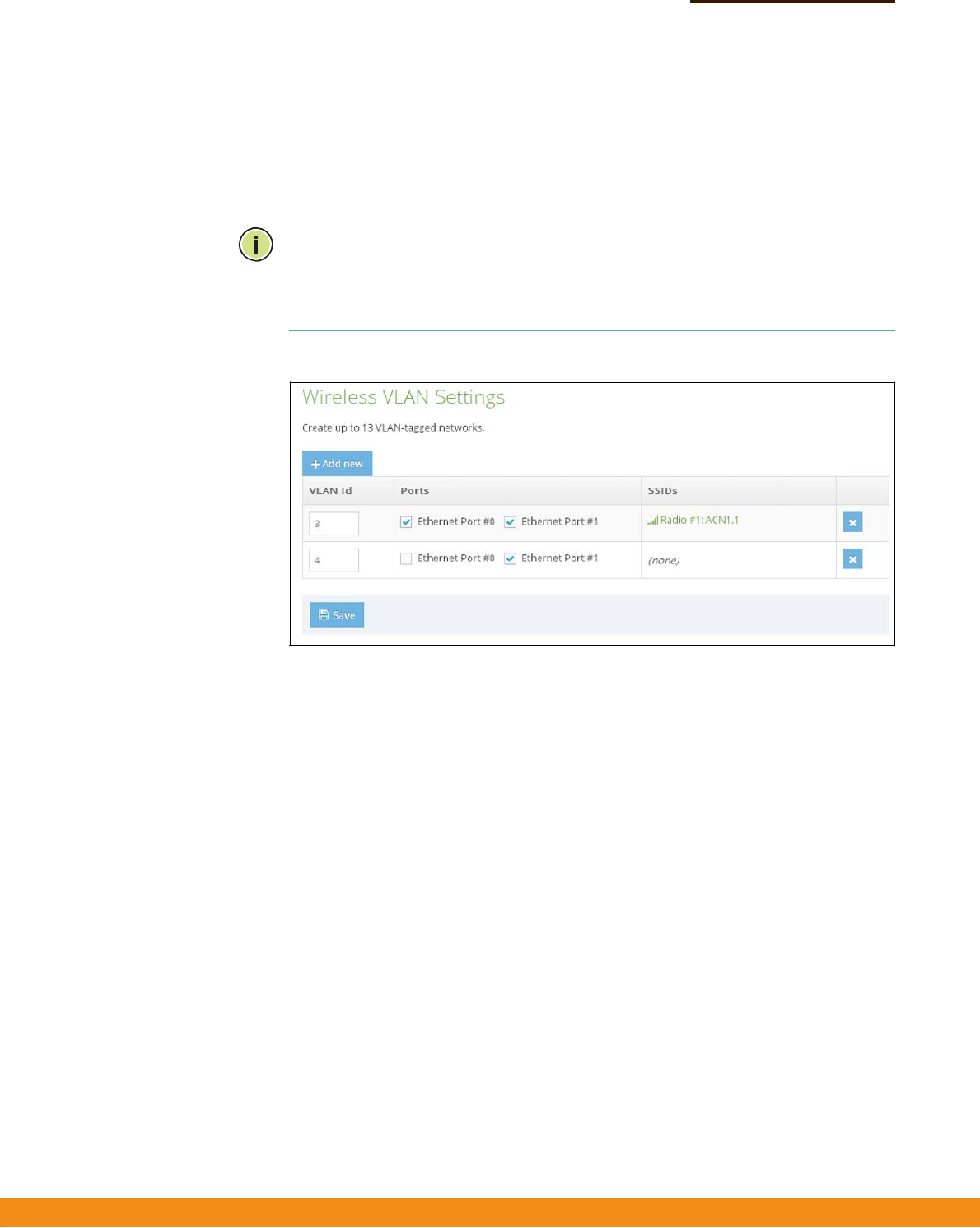
VLANSettings
VLANs(virtuallocalareanetworks)areturnedoffbydefault.Ifturnedontheywill
automaticallytaganypacketspassedtotheLANportfromtherelevantVAP(virtual
accesspoint).
TheaccesspointcanemployVLANtaggingtocontrolaccesstonetworkresources
andincreasesecurity.VLANsseparatetrafficpassingbetweentheaccesspoint,
associatedclients,andthewirednetwork.YoucanconfigureaVLANforupto13
VAPinterfaces.
Notethefollowingpointsabouttheaccesspoint’sVLANsupport:
◆
IfanEthernetLANportontheaccesspointisassignedaVLANID,anytraffic
enteringthatportmustbealsotaggedwiththesameVLANID.
◆
AmanagementVLANcanbeusedformanagingtheaccesspointthrough
remotemanagementtools,suchasthewebinterface,SSH,TelnetorSNMP.
Theaccesspointcanbeconfiguredtoonlyacceptmanagementtrafficthatis
taggedwiththespecifiedmanagementVLANID.ThisIDmustbeassignedto
theEthernetportsorradiointerfaceswhicharedesignatedtohandle
managementtraffic.
◆
WirelessclientsassociatedtotheaccesspointcanbeassignedtoaVLAN.
WirelessclientsareassignedtotheVLANfortheVAPinterfacewithwhichthey
areassociated.TheaccesspointonlyallowstraffictaggedwithcorrectVLAN
IDstobeforwardedtoassociatedclientsoneachVAPinterface.
◆
WhenVLANsupportisenabledontheaccesspoint,trafficpassedtothewired
networkistaggedwiththeappropriateVLANID.WhenanEthernetportonthe
accesspointisconfiguredasaVLANmember,trafficreceivedfromthewired
–
51
–
Chapter4
|
WirelessSettings
VLANSettings
networkmustalsobetaggedwiththesameVLANID.Receivedtrafficthathas
an
unknownVLANIDornoVLANtagisdropped.
◆
WhenVLANsupportisdisabled,theaccesspointdoesnottagtrafficpassedto
thewirednetworkandignorestheVLANtagsonanyreceivedframes.
Note:
BeforeenablingVLANtaggingontheaccesspoint,besuretoconfigurethe
attachednetworkswitchporttosupporttaggedVLANframesfortheVLANIDs
configuredontheaccesspoint.Otherwise,connectivitytotheaccesspointwillbe
lostwhenyouenabletheVLANfeature.
Figure31:ConfiguringVLANs
Thefollowingitemsaredisplayedonthispage:
◆
VLANID—AVLANidentifiertobeassigned.(Range:3‐4095)
(VLAN1and2arereservedforinternaluse.)
◆
Ports
—TheEthernetportsassignedtothespecifiedVLAN.
◆
SSIDs
—TheSSIDofaVAPconfiguredtobeamemberofthespecifiedVLAN.
ThisoptionisconfiguredunderRadioSettings(NetworkSettings–Network
Behavior).

–
52
–
SystemSettings
Thischapterdescribesmaintenancesettingsontheaccesspoint.Itincludesthe
followingsections:
◆
“SystemSettings”onpage53
◆
“Maintenance”onpage54
◆
“UserAccounts”onpage57
◆
“Services”onpage57
5
–
53
–
Chapter5
|
SystemSettings
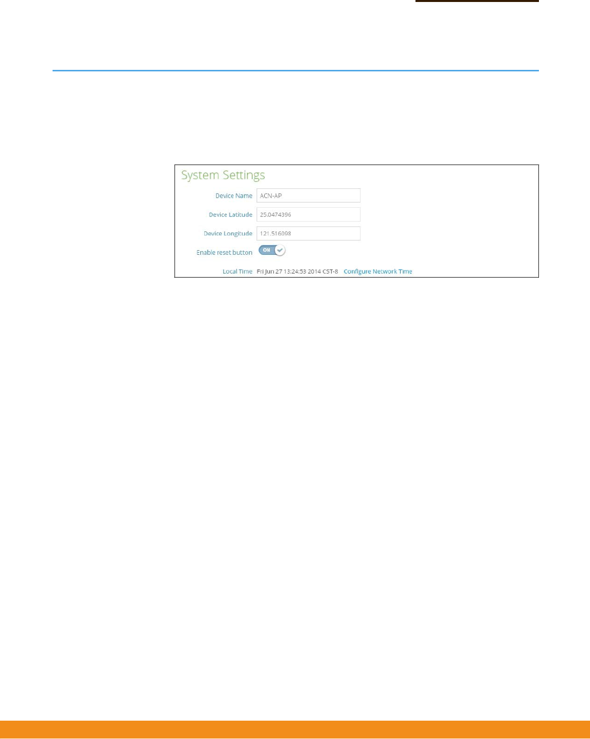
SystemSettings
SystemSettings
TheSystemSettingspageisusedtoconfiguregeneraldescriptiveinformation
abouttheaccesspoint,suchasthesystemidentificationname,itsgeographic
coordinates,andlocaltime.
Figure32:SystemSettings
Thefollowingitemsaredisplayedonthispage:
◆
DeviceName—AnaliasfortheAP,enablingthedevicetobeuniquely
identifiedonthenetwork.(Default:none;Range:0‐50characters)
◆
DeviceLatitude
—Thegeographiclatitudeoftheaccesspoint,givenin
degreesandminutes.(Range:‐ 90to+90degrees)
◆
DeviceLongitude
—Thegeographiclongitudeoftheaccesspoint,givenin
degreesandminutes.(Range:‐ 180to+180degrees)
◆
Enableresetbutton
—Enablesordisablesthehardwareresetbutton.
◆
LocalTime—Thelocaltime,givenasdayofweek,month,time,year.
◆
ConfigureNetworkTime
—LinkstotheNetworkTime(NTP)sectiononthe
Servicespage.
–
54
–
Chapter5
|
SystemSettings
Maintenance
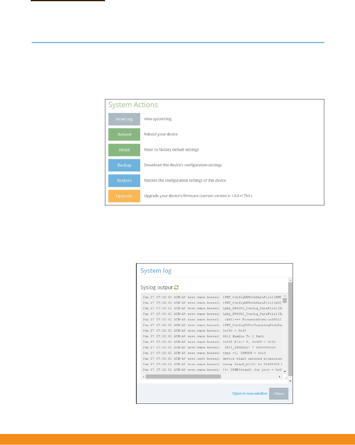
Maintenance
TheMaintenancepagesupportsgeneralmaintenancetasksincludingdisplaying
thesystemlog,rebootingthedevice,restoringfactorydefaults,backingupor
restoringconfigurationsettings,andupgradingfirmware.
Figure33:Maintenance
Displaying
SystemLogs
Theaccesspointsaveseventanderrormessagestoalocalsystemlogdatabase.
Thelogmessagesincludethedateandtime,devicename,messagetype,and
messagedetails.
Figure34:SystemLog

–
55
–
Chapter5
|
SystemSettings
Maintenance
Rebootingthe
AccessPoint
TheRebootpageallowsyoutoreboottheaccesspoint.
Figure35:RebootingtheAccessPoint
Resettingthe
AccessPoint
TheResetpageallowsyoutoresettheaccesspointtothefactorydefaults.Note
thatalluserconfiguredinformationwillbelost.Youwillhavetore‐enterthe
defaultusernameandpasswordtore‐gainmanagementaccesstothisdevice.
Figure36:ResettingtoDefaults
Note:Itisalsopossibletorebootorresettheaccesspointbyinsertingapininthe
pinholelabeled“RESET”ontheconnectorpaneloftheaccesspointand:
◆
press2secondstoreboottheaccesspoint;
◆
press10secondstoresettheaccesspointtothefactorydefaults.
–
56
–
Chapter5
|
SystemSettings
Maintenance
BackingUp
Configuration
Settings
TheBackupfunctionallowsyoutobackuptheaccesspoint’sconfigurationtoa
managementworkstation.InWindows,aGNUZip(*.tar.gz)filewillbestoredinthe
Downloadsfolder.Thisisasamplefilename:backup‐ACN‐AP‐2014‐06‐27.tar.gz
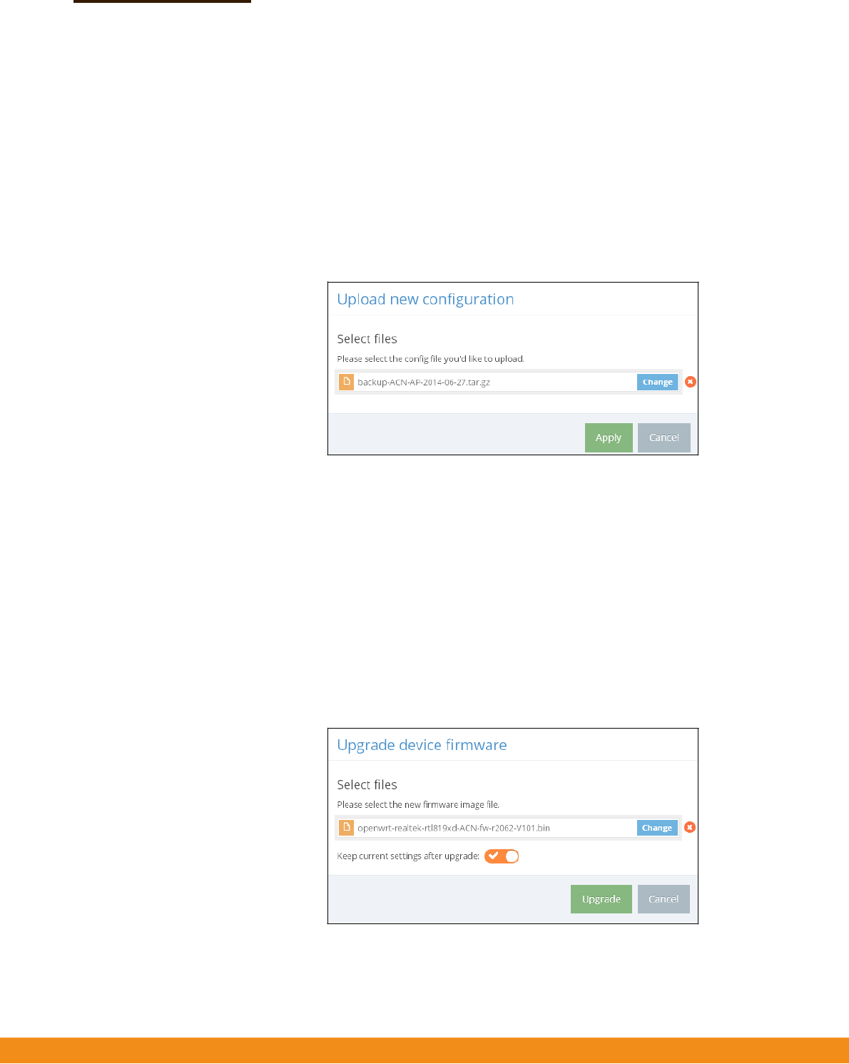
Restoring
Configuration
Settings
TheRestorepageallowsyoutouploadconfigurationsettingsfromamanagement
workstation.Thespecifiedfilemustbeonethatwaspreviouslybackedupfromthe
accesspoint.
Figure37:RestoringConfigurationSettings
UpgradingFirmware Youcanupgradenewaccesspointsoftwarefromalocalfileonthemanagement
workstation.Newsoftwaremaybeprovidedperiodicallyfromyourdistributor.
Afterupgradingnewsoftware,youmustreboottheaccesspointtoimplementthe
newcode.Untilarebootoccurs,theaccesspointwillcontinuetorunthesoftware
itwasusingbeforetheupgradestarted.Theaccesspointsupportsdualsoftware
images,soifnewlyloadedsoftwareiscorrupted,thealternateimagewillbeused
onthenextreboot.Configurationsettingsarestoredseparatelyfromthesoftware,
sothecurrentsettingswillalwaysbeusedforanynewsoftware.However,note
thatifthecurrentconfigurtionsettingsarecorrupted,thesystemdefaultswillbe
used.
Figure38:UpgradingFirmware
–
57
–
Chapter5
|
SystemSettings
UserAccounts
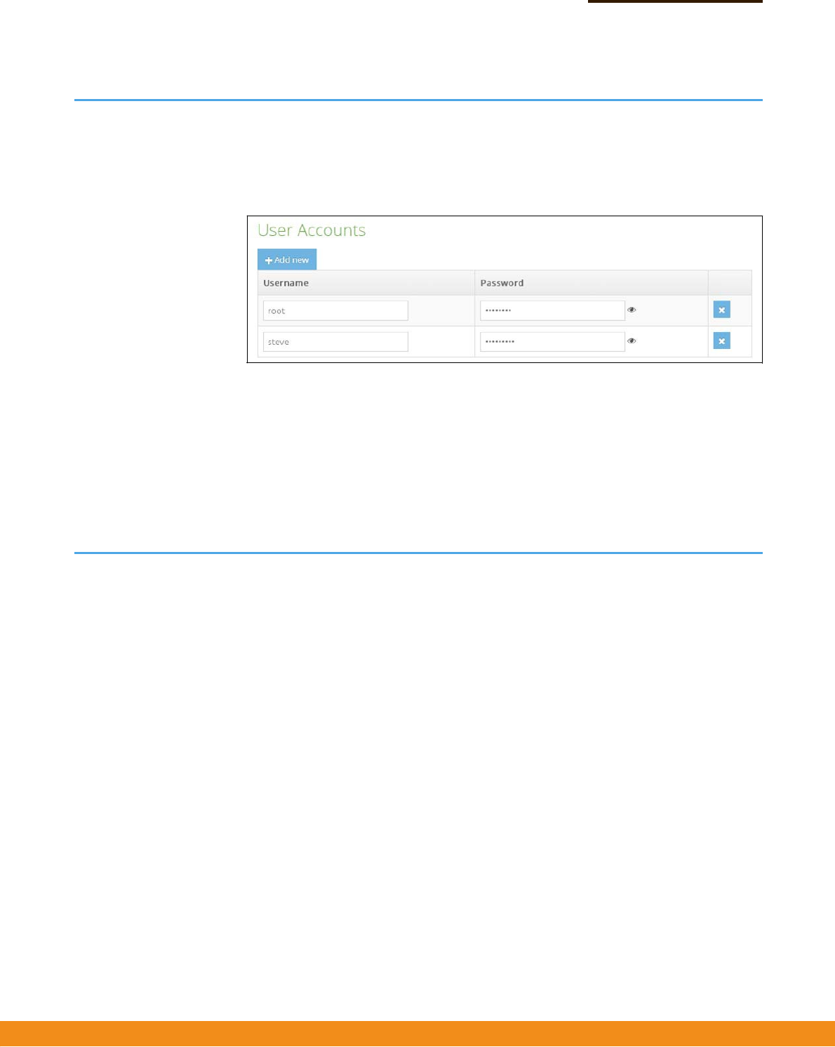
UserAccounts
TheUserAccountspageallowsyoutocontrolmanagementaccesstotheswitch
basedonmanuallyconfiguredusernamesandpasswords.
Figure39:UserAccounts
Thefollowingitemsaredisplayedonthispage:
◆
Username—Thenameoftheuser.(Range:3‐15ASCIIcharacters,nospecial
characters)
◆
Password—Theuserpassword.(Range:3‐15ASCIIcharacters,casesensitive,
nospecialcharacters)
Services
TheServicespageallowsyoutocontrolremotemanagementaccesstotheswitch
andtoconfigureofNTPtimeservers.
RemoteManagement
Settings
TheSSH,Telnet,Web,andSNMPmanagementinterfacesareenabledandopento
accessfromtheInternet.Toprovidemoresecurity,specificservicescanbedisabled
andmanagementaccesspreventedfromtheInternet.
SSH TheSecureShell(SSH)canactasasecurereplacementforTelnet.TheSSHprotocol
usesgeneratedpublickeystoencryptalldatatransferspassingbetweentheaccess
pointandSSH‐enabledmanagementstationclientsandensuresthatdatatraveling
overthenetworkarrivesunaltered.Clientscanthensecurelyusethelocaluser
nameandpasswordforaccessauthentication.
NotethatSSHclientsoftwareneedstobeinstalledonthemanagementstationto
accesstheaccesspointformanagementviatheSSHprotocol.
–
58
–
Chapter5
|
SystemSettings
Services
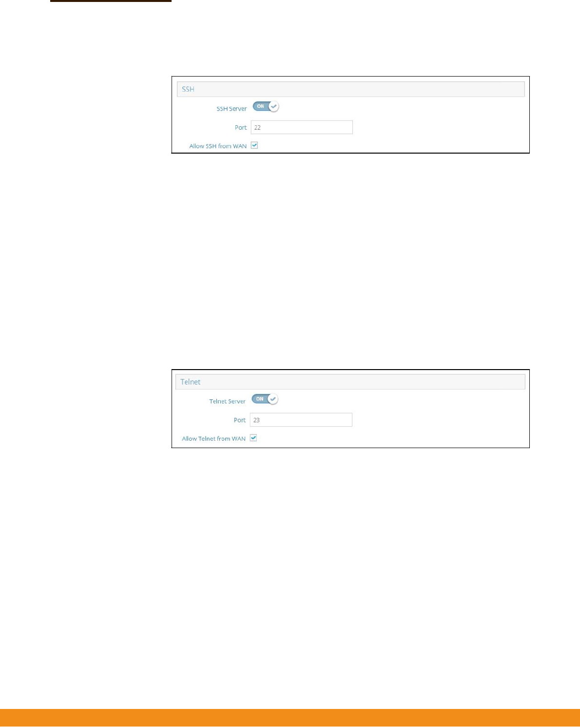
Figure40:SSHServerSettings
Thefollowingitemsaredisplayedonthispage:
◆
SSHServer
—EnablesordisablesSSHaccesstotheaccesspoint.
(Default:Enabled)
◆
Port—SetstheTCPportnumberfortheSSHserverontheaccesspoint.
(Range:1‐65535;Default:22)
◆
AllowSSHfromWAN
—AllowsSSHmanagementaccessfromtheWAN.
TelnetTelnetisaremotemanagementtoolthatcanbeusedtoconfiguretheaccesspoint
fromanywhereinthenetwork.However,notethatTelnetisnotsecurefromhostile
attacks.
Figure41:TelnetServerSettings
Thefollowingitemsaredisplayedonthispage:
◆
TelnetServer
—EnablesordisablesTelnetaccesstotheaccesspoint.
(Default:Enabled)
◆
Port—SetstheTCPportnumberfortheTelnetserverontheaccesspoint.
(Range:1‐65535;Default:23)
◆
AllowTelnetfromWAN
—AllowsTelnetmanagementaccessfromtheWAN.
WebserverAWebbrowserprovidestheprimarymethodofmanagingtheaccesspoint.Both
HTTPandHTTPSservicecanbeaccessedindependently.IfyouenableHTTPS,you
mustindicatethisintheURL:https://device:port_number]
WhenyoustartHTTPS,theconnectionisestablishedinthisway:
–
59
–
Chapter5
|
SystemSettings
Services
◆
Theclientauthenticatestheserverusingtheserver’sdigitalcertificate.
◆
Theclientandservernegotiateasetofsecurityprotocolstouseforthe
connection.
◆
Theclientandservergeneratesessionkeysforencryptinganddecryptingdata.
◆
Theclientandserverestablishasecureencryptedconnection.
◆
Apadlockiconshouldappearinthestatusbarformostbrowsers.
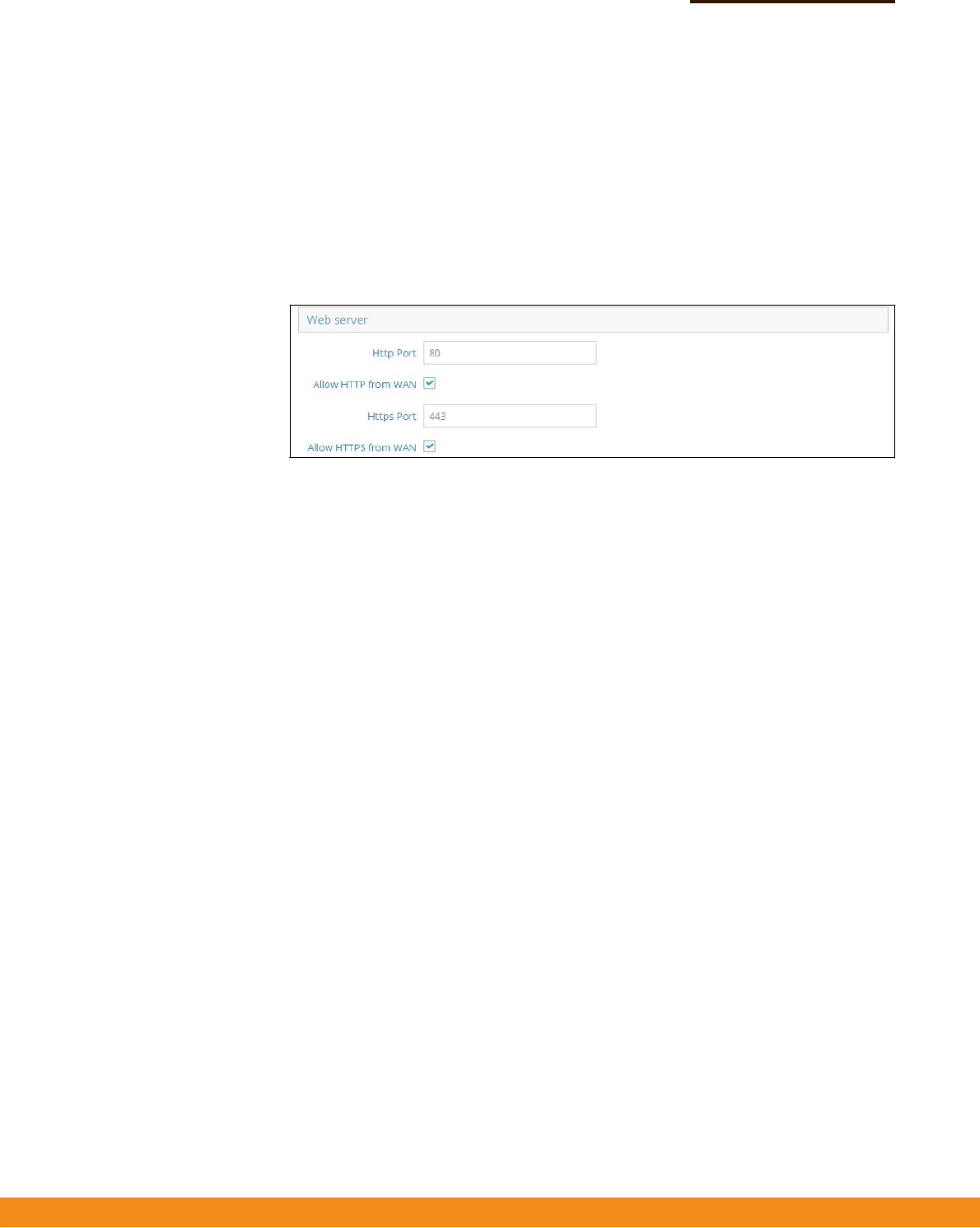
Figure42:WebServerSettings
Thefollowingitemsaredisplayedonthispage:
◆
HTTPPort—TheTCPporttobeusedbytheHTTPWebbrowserinterface.
(Range:1‐65535;Default:80)
◆
AllowHTTPfromWAN
—AllowsHTTPmanagementaccessfromtheWAN.
◆
HTTPSPort—TheTCPporttobeusedbytheHTTPSWebbrowserinterface.
(Range:1‐65535;Default:443)
◆
AllowHTTPSfromWAN
—AllowsHTTPSmanagementaccessfromtheWAN.
NetworkTime NetworkTimeProtocol(NTP)allowstheaccesspointtosetitsinternalclockbased
onperiodicupdatesfromatimeserver(SNTPorNTP).Maintaininganaccuratetime
ontheaccesspointenablesthesystemlogtorecordmeaningfuldatesandtimes
forevententries.Iftheclockisnotset,theaccesspointwillonlyrecordthetime
fromthefactorydefaultsetatthelastbootup.
TheaccesspointactsasanNTPclient,periodicallysendingtimesynchronization
requeststospecifiedtimeservers.Theaccesspointwillattempttopolleachserver
intheconfiguredsequence.
–
60
–
Chapter5
|
SystemSettings
Services
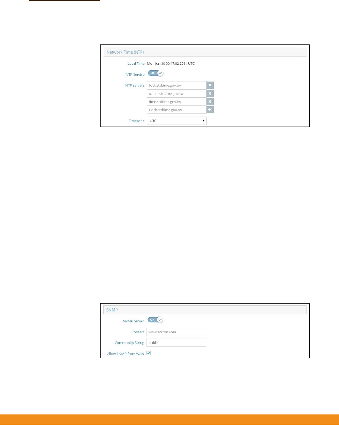
Figure43:NTPSettings
Thefollowingitemsaredisplayedonthispage:
◆
LocalTime—Displaysthelocaltimeasdayofweek,month,
hour:minute:second,year,basedonUniversalTimeCoordinates.
◆
NTPService—Enablesordisablessendingofrequestsfortimeupdates.
(Default:Enabled)
◆
NTPServers—Setsthehostnamesfortimeservers.Theswitchattemptsto
updatethetimefromthefirstserver,ifthisfailsitattemptsanupdatefromthe
nextserverinthesequence.Toconfigureadditionalservers,clickthe“+”
buttontoopenaneweditfield.
◆
TimeZone
—Todisplayatimecorrespondingtoyourlocaltime,chooseone
ofthepredefinedtimezonesfromthescroll‐downlist.
SNMPSimpleNetworkManagementProtocol(SNMP)isacommunicationprotocol
designedspecificallyformanagingdevicesonanetwork.Itistypicallyusedto
configurethesedevicesforproperoperationinanetworkenvironment,aswellas
tomonitorthemtoevaluateperformanceordetectpotentialproblems.
Figure44:SNMPSettings
Thefollowingitemsaredisplayedonthispage:
◆
SNMPServer
—EnablesordisablesSNMPontheaccesspoint.
(Default:Enabled)

–
61
–
Chapter5
|
SystemSettings
Services
◆
Contact—Administratorresponsiblefortheaccesspoint.
◆
CommunityString—Acommunitystringthatactslikeapasswordand
permitsaccesstotheSNMPprotocol.(Range:1‐32characters,casesensitive;
Default:public)
Thedefaultstring“public”providesread‐onlyaccesstotheaccesspoint’s
ManagementInformation(MIB)database.
◆
AllowSNMPfromWAN
—AllowsSNMPmanagementaccessfromtheWAN.

–
61
–
Appendices
Thissectionprovidesadditionalinformationandincludestheseitems:
◆
“Troubleshooting”onpage62
SectionIII

–
62
–
Tro u b l e s h o o t i n g
ProblemsAccessingtheManagementInterface
Table5:TroubleshootingChart
Cannotconnectusing
Telnet,webbrowser,or
SNMPsoftware
◆
BesuretheAPispoweredup.
◆
Checknetworkcablingbetweenthemanagementstationandthe
AP.
◆
CheckthatyouhaveavalidnetworkconnectiontotheAPand
thatintermediateswitchportshavenotbeendisabled.
◆
BesureyouhaveconfiguredtheAPwithavalidIPaddress,subnet
maskanddefaultgateway.
◆
BesurethemanagementstationhasanIPaddressinthesame
subnetastheAP’sIP.
◆
IfyouaretryingtoconnecttotheAPusingataggedVLANgroup,
yourmanagementstation,andtheportsconnectingintermediate
switchesinthenetwork,mustbeconfiguredwiththeappropriate
tag.
◆
IfyoucannotconnectusingTelnet,youmayhaveexceededthe
maximumnumberofconcurrentTelnet/SSHsessionspermitted.
Tryconnectingagainatalatertime.
Forgotorlostthepassword◆ ResettheAPtofactorydefaultsusingitsResetbutton.
UsingSystemLogs
Ifafaultdoesoccur,refertotheQuickStartGuidetoensurethattheproblemyou
encounteredisactuallycausedbytheAP.Iftheproblemappearstobecausedby
theAP,followthesesteps:
1.
EnableSNMPintheSystem>Servciesmenu.
2.
EnableSNMPaccessfromtheWANwhenconnectingfromaremotelocation.
3.
Repeatthesequenceofcommandsorotheractionsthatleaduptotheerror.
4.
Makealistofthecommandsorcircumstancesthatledtothefault.Alsomakea
listofanyerrormessagesdisplayed.
5.
Recordallrelevantsystemsettings.
Symptom
Action
A

–
63
–
ChapterA
|
Troubleshooting
UsingSystemLogs
6.
DisplaythelogfilethroughtheSystem>Maintenancemenu,andcopythe
informationfromthelogfile.
7.
Contactyourdistributor’sserviceengineer,andsendadetaileddescriptionof
theproblem,alongwithalloftheinformationmentionedintheabovesteps.

–
64
–
QuickStart Guide
–
2
–
FollowthestepsinthisguidetoinstalltheAPinyournetwork.
Caution:
TheplanningandinstallationoftheAPrequiresprofessionalpersonnel
thataretrainedintheinstallationofradiotransmittingequipment.Theuseris
responsibleforcompliancewithlocalregulationsconcerningitemssuchas
antennapower,useoflightningarrestors,grounding,andradiomastortower
construction.Therefore,itisrecommendedtoconsultaprofessionalcontractor
knowledgeableinlocalradioregulationspriortoequipmentinstallation.
1.
UnpacktheAP
UnpacktheAPandcheckthepackagecontents.
◆
OutdoorStand‐AloneAccessPoint
SkyFireAC866
◆
Pole‐mountingkit—includestwosteel‐bandclamps
◆
PoEpowerinjectorwithpowercord—eitherUS,ContinentalEuropeorUK
◆
Documentation—QuickStartGuideandRegulatoryandSafetyInformation
2.
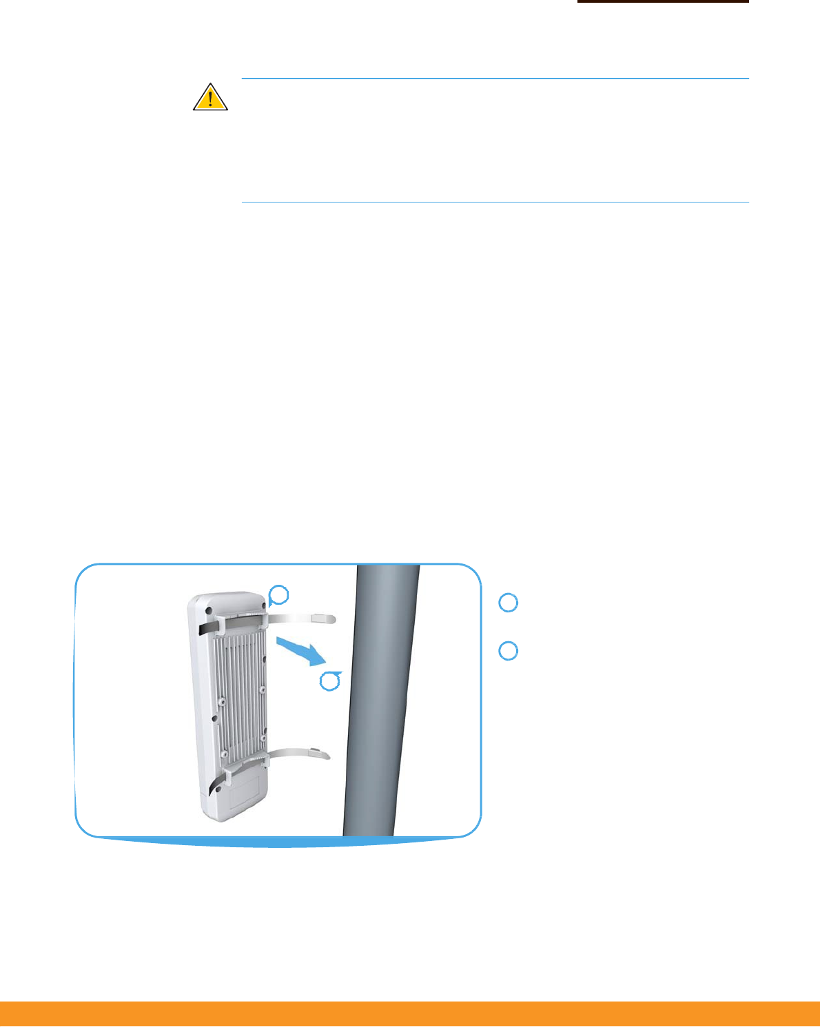
MounttheAP Afterplanningyourinstallation,mounttheunitonapole,mast,ortowerusingthe
includedtwosteel‐bandclamps.
Also,formodelsthatrequireexternalantennas,installtheantennasneartheAP
andattachtheRFcoaxialcablestotheappropriateconnectorsontheAP.
PoleMounting
Feedthesteel‐bandclampsthroughthe
integratedpole‐mountbracketpointson
thebackoftheAP.
Fastenthesteel‐bandclampsaroundthe
poletosecuretheAPtothepole.
1
2
1
2
QuickStart Guide
–
3
–
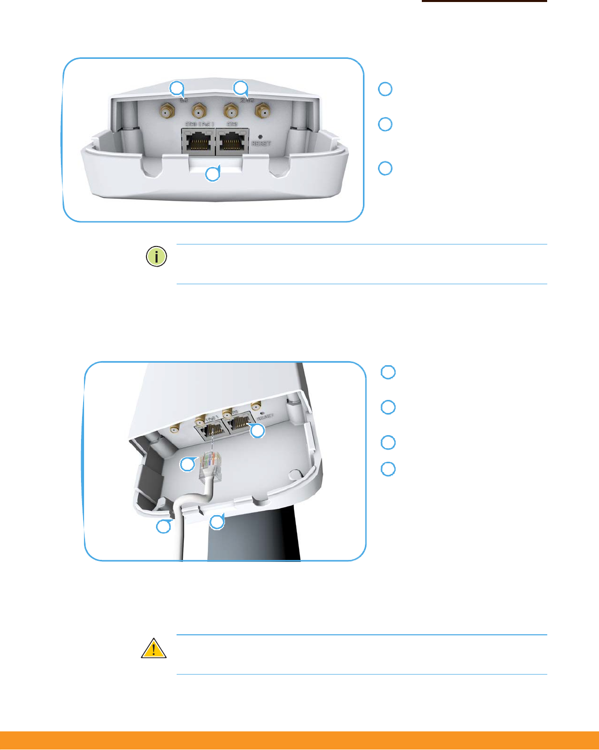
AttachExternalAntennas
Removethefrontportcoverby
pushingthelockingtabupandthen
slidingthecoveroff.
Connectexternalantennastothe
AP’s5GHzRP‐SMAconnectorsusing
RFcoaxialcableprovidedinthe
antennapackage.
Connectexternalantennastothe
AP’s2.4GHzRP‐SMAconnectors
usingRFcoaxialcableprovidedinthe
antennapackage.
Note:Thenumberofavailable2.4GHzor5GHzexternalantennaconnectors
dependsonthespecificmodel.
3.
ConnectCablesConnectoutdoor‐ratedEthernetcabletothe1000BASE‐TRJ‐45ETH0(PoE)porton
theunit.
Connectoutdoor‐ratedCategory5e
orbettercabletotheleft‐sideRJ‐45
ETH0(PoE)port.
(Optional)ConnectalocalLAN
switchorcomputertotheright‐side
ETH1100BASE‐TXRJ‐45port.
Passthecablesthroughtheaccess
holesatthebottomoftheAP.
ReplacetheportcoverontheAPand
pushthelockingtabdowntosecure
itinplace.
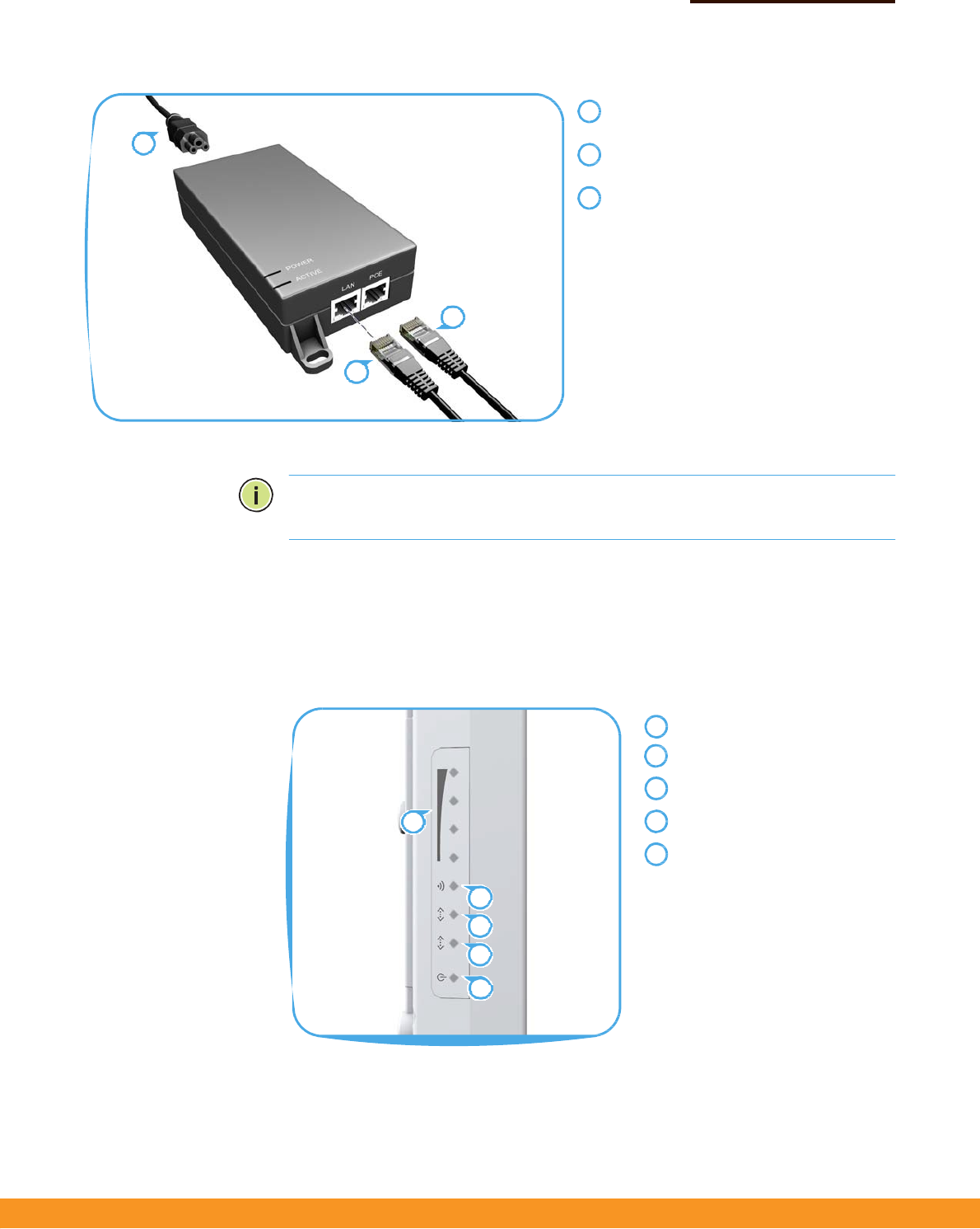
4.
ConnectPower InstallthePoEpowerinjectorindoors.ConnectthepowerinjectortotheEthernet
cablefromtheAP,toaportonalocalLANswitch,andthentoanACpowersource.
Caution:
Thepowerinjectormoduleisdesignedforindooruseonly.Nevermount
thepowerinjectoroutsidewiththeAPunit.
23
1
1
2
3
1
2
2
3
14
34
QuickStart Guide
–
4
–
ConnecttheEthernetcablefromtheAPto
the“POE”portonthepowerinjector.
ConnectEthernetcablefromthe“LAN”port
onthepowerinjectortoaLANswitch.
ConnectthepowercordtoanearbyAC
powersource(100‐240VAC,50/60Hz).
Note
:
ConnectingtheEthernetcablefromtheAPtotheinjectormodulepowers
ontheunit.
5.
VerifyAPOperation
VerifybasicAPoperationbycheckingthesystemLEDs.
ThepowerLEDshouldbeongreen,theETH0portLEDon/blinkinggreen,andthe
5GHzwirelessLED/blue(5GHz).
5GHzsignalstrength
LEDs.
5GHzlink/activityLED.
ETH1
portlink/activityLED.
ETH0(PoE)
portlink/activityLED.
PowerLED.
1
3
2
3
1
2
1
2
3
4
5
1
2
3
4
5

QuickStart Guide
–
5
–
6.
ConnecttotheWeb
UserInterface
Thestand‐aloneAPsofferaweb‐basedmanagementinterfaceforthe
configurationofalltheunit’sfeatures.
YoucanmakeinitialconfigurationchangesbyconnectingaPCdirectlytotheAP’s
ETH1RJ‐45port.TheAPhasadefaultmanagementIPaddressof192.168.2.1anda
subnetmaskof255.255.255.0.YoumustsetyourPCIPaddresstobeonthesame
subnetastheAP(thatis,thePCandAPaddressesmustbothstart192.168.2.x).
Logintothewebinterfaceusingthedefaultsettings:
◆
LoginName—root
◆
Password—admin123
Formoreinformationonstand‐aloneAPconfigurationusingthewebinterface,
refertotheManagementGuide.

QuickStart Guide
–
6
–
HardwareSpecifications
Chassis
Size(HxWxD:)283x94x50mm(11.14x3.7x1.97inches)
Weight
762g(1.68lb)
TemperatureOperating:‐20°Cto65°C(‐4°Fto149°F)
Storage:‐30°Cto80°C(‐22°Fto176°F)
Humidity
Operating:15%to95%(non‐condensing)
Waterproof/Dustproof
IP55
NetworkInterfaces
PortsETH0(PoE)RJ‐45Port:1000BASE‐T,passivePoE
ETH1RJ‐45Port:100BASE‐TX
2.4GHzRadioIEEE802.11b/g/n
5GHzRadioIEEE802.11a/n/ac
RadioFrequencies5745~5825MHz(China)
5180~5240MHz(NCC)
5260~5230MHz(NCC)
5745~5825MHz(NCC)
PowerSupply
PoEInputPower24VDC,1.0A
PowerConsumption24Wmaximum
PowerInjectorModule100‐240VAC,50‐60Hz,auto‐sensing
RegulatoryCompliances
RadioEN300328V1.8.1:2012
EN301893V1.7.1:2012
EN301489‐1V1.9.2(2011‐09)
EN301489‐7V1.3.1:2005
FCCPart15E15.407(5.150GHz‐5.250GHz)
EmissionsEN550222010+AC:2011
EN61000‐3‐22006+A1:2009+A2:2009
FCCClassBPart15
ImmunityEN55024:2010
EN61000‐4‐2:2009
ItemSpecification

QuickStart Guide
–
7
–
FederalCommunicationCommissionInterferenceStatement
ThisdevicecomplieswithPart15oftheFCCRules.Operationissubjecttothefollowingtwoconditions:(
1)Thisdevicemaynotcauseharmfulinterference,and
(2)thisdevicemustacceptanyinterferencereceived,includinginterferencethatmaycauseundesiredoperation.
ThisequipmenthasbeentestedandfoundtocomplywiththelimitsforaClassBdigitaldevice,pursuanttoPart15
oftheFCCRules.Theselimitsaredesignedtoprovidereasonableprotectionagainstharmfulinterferenceina
residentialinstallation.Thisequipmentgenerates,usesandcanradiateradiofrequencyenergyand,ifnotinstalled
andusedinaccordancewiththeinstructions,maycauseharmfulinterferencetoradiocommunications.However,
thereisnoguaranteethatinterferencewillnotoccurinaparticularinstallation.Ifthisequipmentdoescause
harmfulinterferencetoradioortelevisionreception,whichcanbedeterminedbyturningtheequipmentoffandon,
theuserisencouragedtotrytocorrecttheinterferencebyoneofthefollowingmeasures:
‐ Reorientorrelocatethereceivingantenna.
‐ Increasetheseparationbetweentheequipmentandreceiver.
‐ Connecttheequipmentintoanoutletonacircuitdifferentfromthat
towhichthereceiverisconnected.
‐ Consultthedealeroranexperiencedradio/TVtechnicianforhelp.
FCCCaution:Anychangesormodificationsnotexpresslyapprovedbythepartyresponsibleforcompliancecouldvoid
theuser'sauthoritytooperatethisequipment.
Thistransmittermustnotbeco‐locatedoroperatinginconjunctionwithanyotherantennaortransmitter.
Foroperationwithin5.15~5.25GHz/5.47~5.725GHzfrequencyrange,itisrestrictedtoindoorenvironment.
Thebandfrom5600‐5650MHzwillbedisabledbythesoftwareduringthemanufacturingandcannotbechanged
bytheenduser.ThisdevicemeetsalltheotherrequirementsspecifiedinPart15E,Section15.407oftheFCCRules.
RadiationExposureStatement:
ThisequipmentcomplieswithFCCradiationexposurelimitssetforthforanuncontrolledenvironment.
Thisequipmentshouldbeinstalledandoperatedwithminimumdistance20cmbetweentheradiator&yourbody.
Note:Thecountrycodeselectionisfornon‐USmodelonlyandisnotavailabletoallUSmodel.
PerFCCregulation,allWiFiproductmarketedinUSmustfixedtoUSoperationchannelsonly.

QuickStart Guide
–
8
–
Professionalinstallationinstruction
1.Installationpersonal
ThisproductisdesignedforspecificapplicationandneedstobeinstalledbyaqualifiedpersonalwhohasRFand
relatedruleknowledge.Thegeneralusershallnotattempttoinstallorchangethesetting.
2.Installationlocation
Theproductshallbeinstalledatalocationwheretheradiatingantennacanbekept20cmfromnearbypersonin
normaloperationconditiontomeetregulatoryRFexposurerequirement.
3.Externalantenna
Useonlytheantennaswhichhavebeenapprovedbytheapplicant.Thenon‐approvedantenna(s)mayproduce
unwantedspuriousorexcessiveRFtransmittingpowerwhichmayleadtotheviolationofFCClimitandisprohibited.
4.Installationprocedure
Pleaserefertouser’smanualforthedetail.
5.Warning
Pleasecarefullyselecttheinstallationpositionandmakesurethatthefinaloutputpowerdoesnotexceedthe
limitsetforceinrelevantrules.Theviolationoftherulecouldleadtoseriousfederalpenalty.
professionalinstaller:5.15‐5.25Gband(UNIIband1)iscertifiedtoindooruseonly.InstallermustdisableUNIIband1byprovidedproprietarytool
whenyouinstallthisdeviceforoutdoorapplicationtocomplywithFCCrequirement.
低功率電波輻射性電機管理辦法
第十二條 經型式認證合格之低功率射頻電機,非經許可,公司、商號或使用者均不得擅自變更頻率、
加大功率或變更原設計之特性及功能。
第十四條 低功率射頻電機之使用不得影響飛航安全及干擾合法通信;經發現有干擾現象時,應立即停用,
並改善至無干擾時方得繼續使用。前項合法通信,指依電信法規定作業之無線電通信。低功率射頻電機須忍受合法通信或工業、
科學及醫療用電波輻射性電機設備之干擾。
此器材須經專業安裝並限用於固定式點對點操作。
本器材須經專業工程人員安裝及設定,始得設置使用,且不得直接販售給一般消費者。
「電磁波曝露量MPE標準值1mW/cm2,送測產品實測值為 0.682 mW/cm2」