Accton Technology ACCWA5001 Wireless LAN Access Point User Manual UsersGuide rev 2
Accton Technology Corp Wireless LAN Access Point UsersGuide rev 2
UserManual.wiki
>
Accton Technology
>
ACCWA5001 User Manual
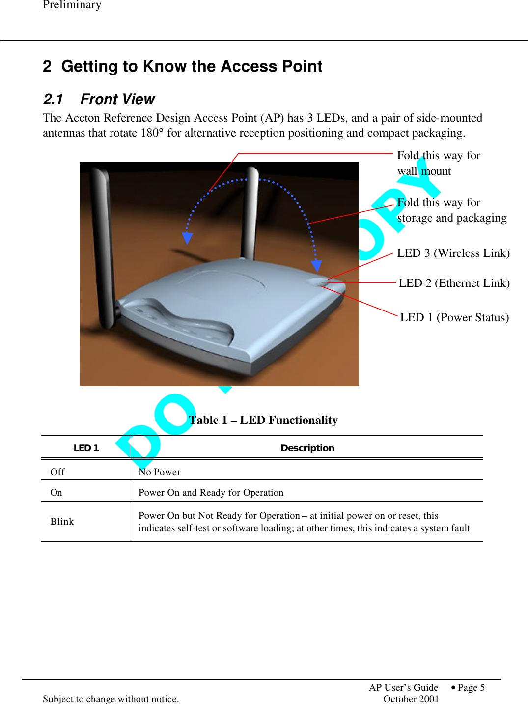
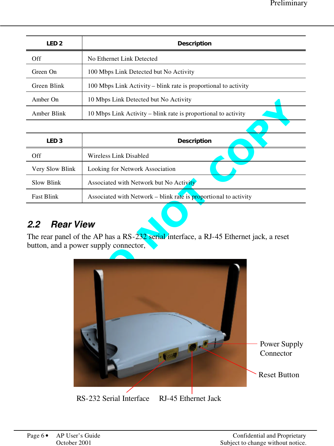
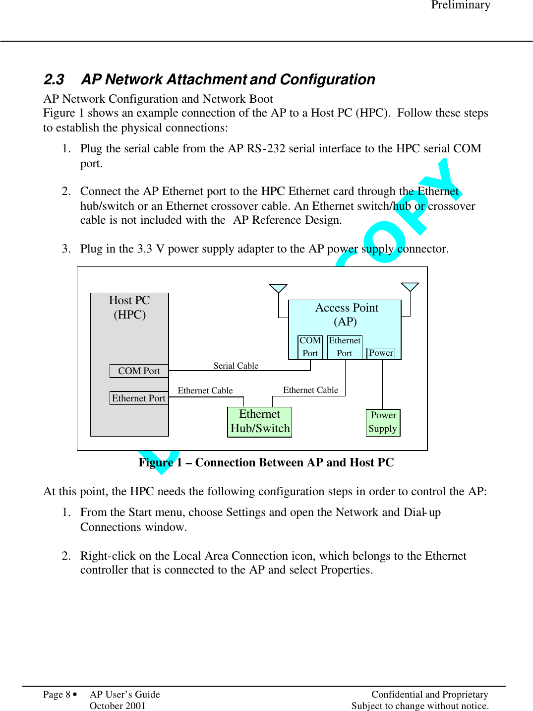
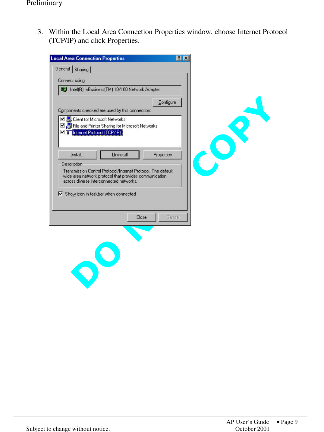
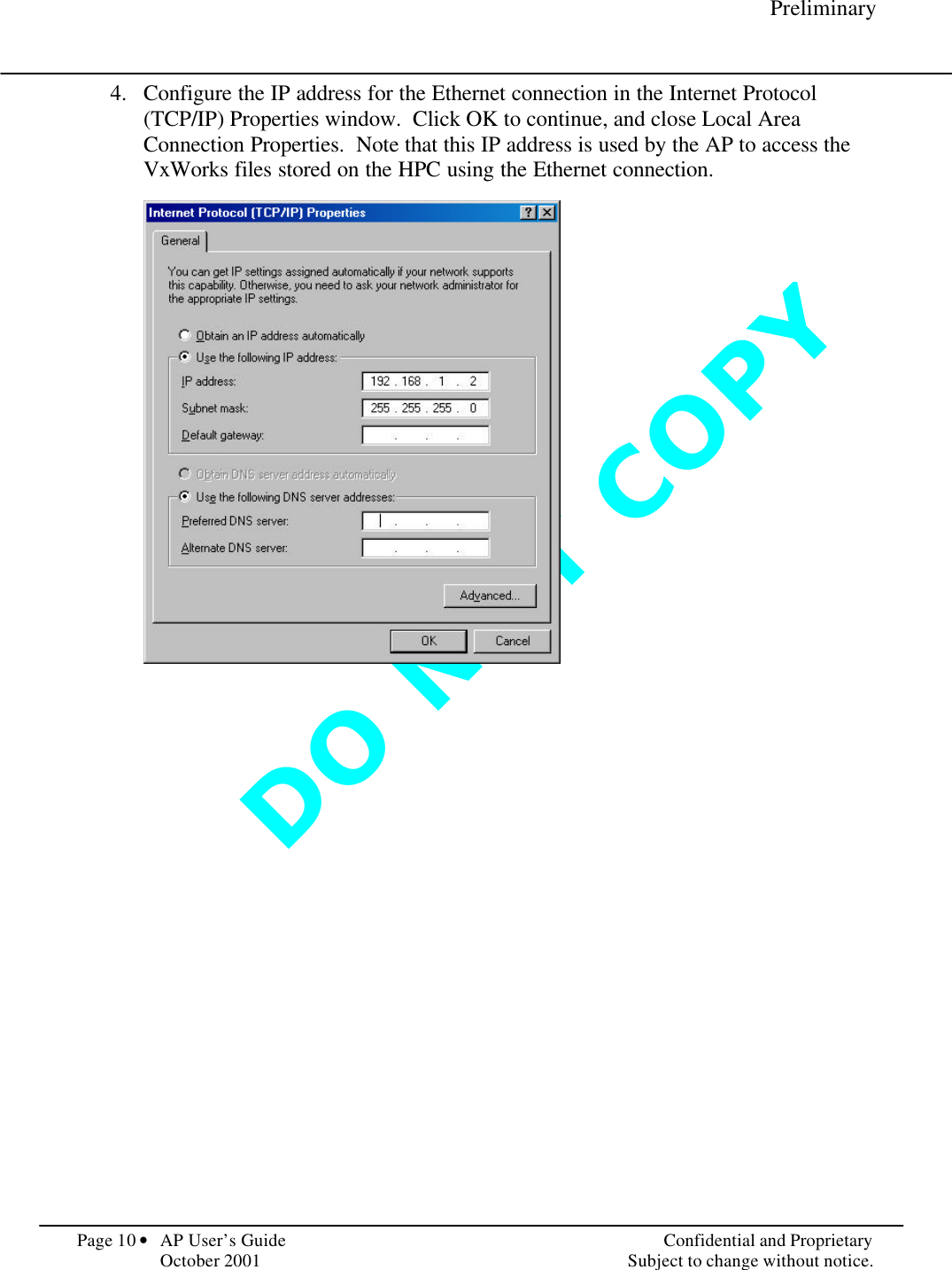
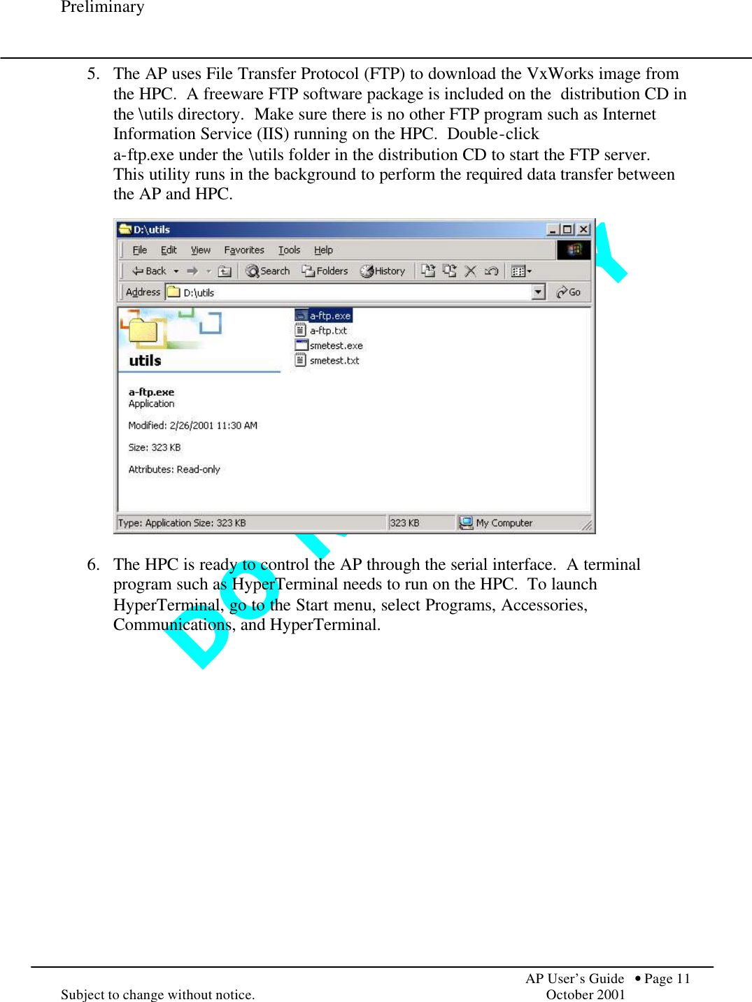
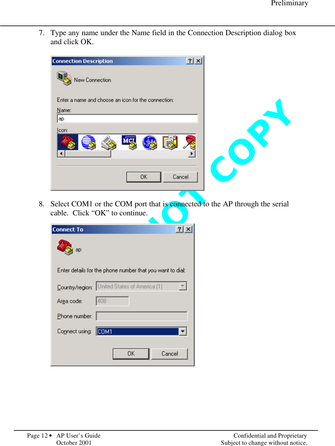
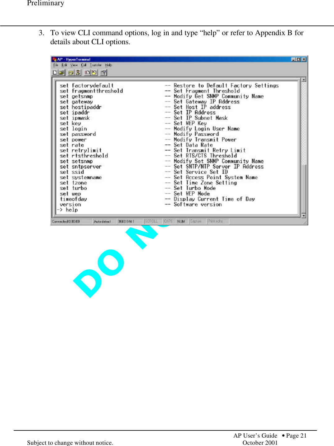
User Guide
Navigation menu
Upload a User Manual
Namespaces
Wiki Guide
HTML
PDF
Info
Views
User Manual
Discussion / Help
Navigation