Accton Technology CAP2315A 802.11b/g AP Cradle User Manual install guide
Accton Technology Corp 802.11b/g AP Cradle install guide
Users Manual
WA6102-ZZ
CAP2315A
802.11b/g AP Cradle
Installation Guide

Installation Guide
Guide
802.11b/g AP Cradle
IEEE 802.11b/g Wireless Access Point,
with Cradle Charger for Wi-Fi Phone

CAP2315A
E072006-EK-R01
150xxxxxxxxxxxx

i
Compliances
Federal Communication Commission Interference Statement
This equipment has been tested and found to comply with the limits for a Class B digital
device, pursuant to Part 15 of the FCC Rules. These limits are designed to provide
reasonable protection against harmful interference in a residential installation. This
equipment generates, uses and can radiate radio frequency energy and, if not installed
and used in accordance with the instructions, may cause harmful interference to radio
communications. However, there is no guarantee that interference will not occur in a
particular installation. If this equipment does cause harmful interference to radio or
television reception, which can be determined by turning the equipment off and on, the
user is encouraged to try to correct the interference by one of the following measures:
• Reorient or relocate the receiving antenna
• Increase the separation between the equipment and receiver
• Connect the equipment into an outlet on a circuit different from that to which the receiver
is connected
• Consult the dealer or an experienced radio/TV technician for help
This device complies with Part 15 of the FCC Rules. Operation is subject to the following
two conditions: (1) This device may not cause harmful interference, and (2) this device
must accept any interference received, including interference that may cause undesired
operation.
FCC Caution: Any changes or modifications not expressly approved by the party
responsible for compliance could void the user's authority to operate this equipment.
IMPORTANT NOTE:
FCC Radiation Exposure Statement
This equipment complies with FCC radiation exposure limits set forth for an uncontrolled
environment. This equipment should be installed and operated with a minimum distance
of 20 centimeters (8 inches) between the radiator and your body. This transmitter must
not be co-located or operating in conjunction with any other antenna or transmitter.
The antenna(s) used for this transmitter must not be co-located or operating in
conjunction with any other antenna or transmitter.
IEEE 802.11b or 802.11g operation of this product in the U.S.A. is firmware-limited to
channels 1 through 11.
Japan VCCI Class B

ii
EC Conformance Declaration
Marking by the above symbol indicates compliance with the Essential Requirements of
the R&TTE Directive of the European Union (1999/5/EC). This equipment meets the
following conformance standards:
• EN 60950-1 (IEC 60950-1) - Product Safety
• EN 300 328 - Technical requirements for 2.4 GHz radio equipment
• EN 301 489-1, EN 301 489-17 - EMC requirements for radio equipment
• EN 50385 - The Compliance of Radio Base Stations and Fixed Terminal Stations for
Wireless Telecommunication Systems with the Basic Restrictions or the Reference
Levels Related to Human Exposure to Radio Frequency Electromagnetic Fields (110
MHz - 40 GHz)
This device is intended for use in the following European Community countries:
Requirements for indoor vs. outdoor operation, license requirements and allowed
channels of operation apply in some countries as described below:
• In Italy the end-user must apply for a license from the national spectrum authority to
operate this device outdoors.
• In Belgium outdoor operation is only permitted using the 2.46 - 2.4835 GHz band:
Channel 13.
• In France outdoor operation is only permitted using the 2.4 - 2.454 GHz band: Channels
1 - 7.
• Austria • Belgium • Denmark
• Finland • France • Germany
• Italy • Luxembourg • Netherlands
• Norway • Spain • Sweden
• Switzerland • United Kingdom • Portugal
• Greece • Ireland • Iceland

iii
Contents
Chapter 1: Introduction 1-1
Package Checklist 1-1
Hardware Description 1-2
Wi-Fi Phone Cradle 1-3
LED Indicators 1-3
Ethernet Port 1-3
Reset Button 1-4
Power Connector 1-4
Chapter 2: Hardware Installation 2-1
Access Point Configuration 2-2
Appendix A: Troubleshooting A-1
Diagnosing Access Point Indicators A-1
Appendix B: Cables and Pinouts B-1
Twisted-Pair Cable Assignments B-1
10/100BASE-TX Pin Assignments B-1
Straight-Through Wiring B-2
Crossover Wiring B-2
Appendix C: Specifications C-1

iv
Contents

1-1
Chapter 1: Introduction
The Cradle Access Point is an IEEE 802.11b/g (Wi-Fi) access point that provides a
quality wireless Voice over Internet Protocol (VoIP) service for Wi-Fi phones, and
high-speed data communications between a wired LAN and other 802.11b/g mobile
devices. The access point also includes a cradle for charging a Wi-Fi phone.
The access point software provides two “virtual” wireless interfaces that separate
the Wi-Fi Phone traffic from the regular data traffic. Quality of Service (QoS) features
ensure sustained high throughput for the voice traffic and channel hopping avoids
radio interference, which helps maintain high-quality voice communications.
The data wireless interface provides gateway functions, such as a DHCP server and
Network Address Translation (NAT), that route data from wireless clients to the wired
network.
In addition, the access point offers full network management capabilities through an
easy-to-use web interface.
Package Checklist
The Cradle Access Point package includes:
• Cradle Access Point
• One Category 5 network cable
• One AC power adapter
• This Installation Guide
• Management Guide CD
Inform your dealer if there are any incorrect, missing or damaged parts. If possible,
retain the carton, including the original packing materials. Use them again to repack
the product in case there is a need to return it.
Introduction
1-2
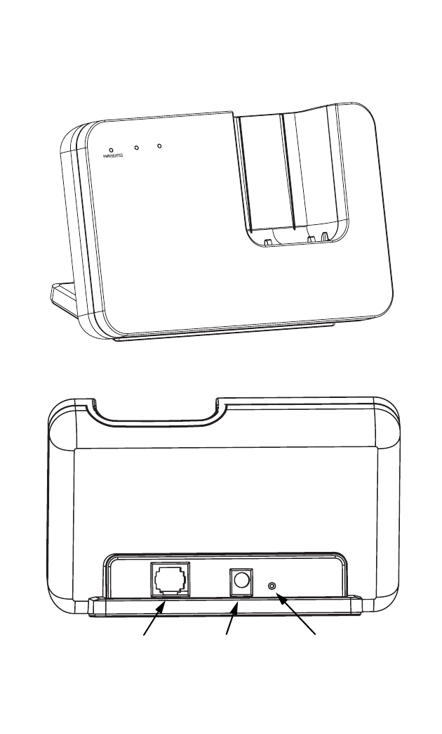
Hardware Description
Front Panel
Back Panel
WLANLAN
Ethernet LAN
RJ-45 Port Power
Socket Reset
Button
Hardware Description
1-3
Wi-Fi Phone Cradle
The access point accepts a Wi-Fi Phone in its cradle for charging the battery. When
the access point is powered on, just place the phone in the cradle and charging
starts immediately.
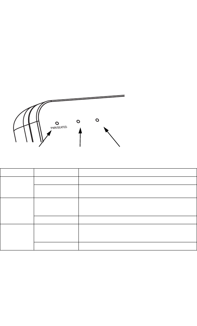
LED Indicators
The access point includes three status LED indicators, as described in the following
figure and table.
Ethernet Port
The access point has one 10BASE-T/100BASE-TX RJ-45 port that can be attached
directly to 10BASE-T/100BASE-TX LAN segments. These segments must conform
to the IEEE 802.3-2005 specifications.
This port supports automatic MDI/MDI-X operation, so you can use straight-through
cables for all network connections to PCs, switches, or hubs.
LED Status Description
PWR/SEATED On Green Indicates that the system is working normally.
On Red The system is working normally with a Wi-Fi phone seated in the
cradle.
WLAN On/Flashing Green Indicates the 802.11g radio is enabled and transmitting or
receiving data through wireless links. The flashing rate is
proportional to network activity.
Off Indicates the 802.11g radio is disabled.
LAN On/Flashing Green Indicates a valid link on the Ethernet port and that the access
point is transmitting or receiving data. The flashing rate is
proportional to network activity.
Off The Ethernet port has no valid link.
WLAN LAN
Power 802.11g
Wireless
Link/Activity
Ethernet
Link/Activity

Introduction
1-4
Reset Button
The Reset button is used to restart the access point or restore the factory default
configuration. If you hold down the button for less than 5 seconds, the access point
will perform a hardware reset. If you hold down the button for 5 seconds or more,
any configuration changes you may have made are removed, and the factory default
configuration is restored to the access point.
Power Connector
The access point does not have a power switch. It is powered on when connected to
the AC power adapter, and the power adapter is connected to a power source. The
power adapter automatically adjusts to any voltage between 100-240 volts at 50 or
60 Hz. No voltage range settings are required.

2-1
Chapter 2: Hardware Installation
To install the Cradle Access Point, follow these steps:
1. Select a Site – Choose a proper place for the access point. In general, the best
location is at the center of your wireless coverage area, within line of sight of all
wireless devices. For optimum performance, consider these points:
• Mount the access point as high as possible above any obstructions in the
coverage area.
• Avoid mounting next to or near building support columns or other obstructions
that may cause reduced signal or null zones in parts of the coverage area.
• Mount away from any signal absorbing or reflecting structures (such as those
containing metal).
• Avoid radio interference by mounting away from other 2.4 GHz devices, such
as other 802.11b or g wireless devices, regular cordless phones, and
microwave ovens.
2. Mount the Access Point – The access point is designed to be mounted on any
horizontal surface, such as a desktop.
3. Connect the Power Cord – Connect the power adapter to the access point,
and plug the power adapter into an AC power outlet.
Caution: Use ONLY the power adapter supplied with the access point. Otherwise, the
product may be damaged.
4. Observe the Indicator LEDs – When you power on the access point verify that
the Power LED turns on and that the other LED indicators start functioning as
described under “LED Indicators” on page 1-3.
5. Connect the Ethernet Cable – The access point can be connected to any 10
or 100 Mbps Ethernet network device, such as a hub or a switch. Connect your
network to the RJ-45 port on the back panel using category 3, 4, or 5 UTP
Ethernet cable. When the access point and the connected device are powered
on, the LAN LED should turn on indicating a valid network connection. If the
LAN LED fails to turn on, refer to “Troubleshooting” on page A-1.
Note: The RJ-45 port on the access point supports automatic MDI/MDI-X operation, so
you can use straight-through cables for all network connections to PCs, switches,
or hubs.

Hardware Installation
2-2
Access Point Configuration
The access point can be configured by connecting a PC to its Ethernet port and
accessing the web interface. The default IP address of the access point is
192.168.1.20, with login user name “admin” and no default password.
For information on configuring the access point, refer to the Management Guide.
A-1
Appendix A: Troubleshooting
Diagnosing Access Point Indicators
Note: For information on troubleshooting wireless connectivity issues, refer to the
Management Guide.
Troubleshooting Chart
Symptom Action
PWR/SEATED LED is Off • AC power adapter may be disconnected. Check connections between
the access point, the power adapter, and the wall outlet.
LAN LED is Off • Verify that the access point and attached device are powered on.
• Be sure the cable is plugged into both the access point and
corresponding device.
• Verify that the proper cable type is used and its length does not exceed
specified limits.
• Check the cable connections for possible defects. Replace the
defective cable if necessary.

Troubleshooting
A-2
B-1
Appendix B: Cables and Pinouts
Twisted-Pair Cable Assignments
For 10/100BASE-TX connections, a twisted-pair cable must have two pairs of wires.
Each wire pair is identified by two different colors. For example, one wire might be
green and the other, green with white stripes. Also, an RJ-45 connector must be
attached to both ends of the cable.
Caution: Each wire pair must be attached to the RJ-45 connectors in a specific
orientation. (See “Straight-Through Wiring” on page B-2 and “Crossover
Wiring” on page B-2 for an explanation.)
Caution: DO NOT plug a phone jack connector into the RJ-45 port. Use only twisted-pair
cables with RJ-45 connectors that conform with FCC standards.
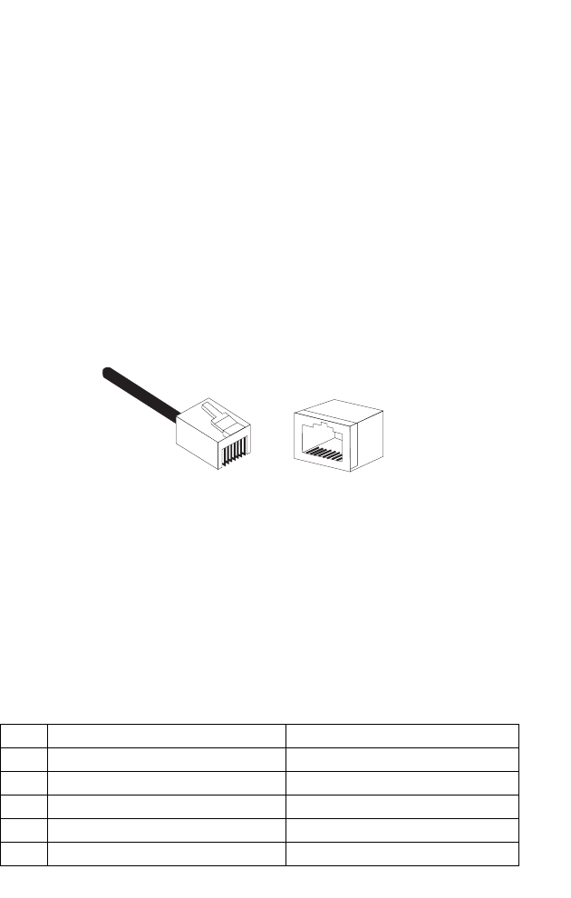
The following figure illustrates how the pins on the RJ-45 connector are numbered.
Be sure to hold the connectors in the same orientation when attaching the wires to
the pins.
10/100BASE-TX Pin Assignments
Use unshielded twisted-pair (UTP) or shielded twisted-pair (STP) cable for RJ-45
connections: 100-ohm Category 3 or better cable for 10 Mbps connections, or
100-ohm Category 5 or better cable for 100 Mbps connections. Also be sure
that the
length of any twisted-pair connection does not exceed 100 meters (328 feet).
The RJ-45 port on the access point supports automatic MDI/MDI-X operation, so
you can use straight-through or crossover cables for all network connections to PCs,
switches, or hubs. In straight-through cable, pins 1, 2, 3, and 6, at one end of the
cable, are connected straight through to pins 1, 2, 3, and 6 at the other end.
Pin MDI Signal Name MDI-X Signal Name
1 Transmit Data plus (TD+) Receive Data plus (RD+)
2 Transmit Data minus (TD-) Receive Data minus (RD-)
3 Receive Data plus (RD+) Transmit Data plus (TD+)
6 Receive Data minus (RD-) Transmit Data minus (TD-)
4,5,7,8 Not used Not used
Note: The “+” and “-” signs represent the polarity of the wires that make up each wire pair.
1
881
Cables and Pinouts
B-2
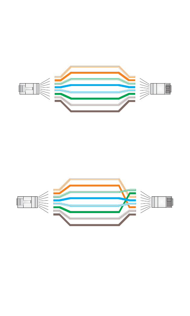
Straight-Through Wiring
If the twisted-pair cable is to join two ports and only one of the ports has an internal
crossover (MDI-X), the two pairs of wires must be straight-through.
Crossover Wiring
If the twisted-pair cable is to join two ports and either both ports are labeled with an
“X” (MDI-X) or neither port is labeled with an “X” (MDI), a crossover must be
implemented in the wiring.
White/Orange Stripe
Orange
White/Green Stripe
Green
1
2
3
4
5
6
7
8
1
2
3
4
5
6
7
8
EIA
/
TIA 568B RJ-45 Wiring
S
tandard
10/100BASE-TX Straight-through Cable
End A End B
Blue
White/Blue Stripe
Brown
White/Brown Stripe
White/Orange Stripe
Orange
White/Green Stripe
1
2
3
4
5
6
7
8
1
2
3
4
5
6
7
8
EIA/TIA 568B RJ-45 Wiring Standard
10/100BASE-TX Crossover Cable
End A End B
Green
Blue
White/Blue Stripe
Brown
White/Brown Stripe

C-1
Appendix C: Specifications
Maximum Channels
FCC/IC: 1-11
ETSI: 1-13
France: 10-13
MKK: 1-14
Taiwan: 1-11
Maximum Clients
32 per VAP interface
Data Rate
802.11g: 6, 9, 11, 12, 18, 24, 36, 48, 54 Mbps per channel
802.11b: 1, 2, 5.5, 11 Mbps per channel
Modulation Type
802.11g: CCK, BPSK, QPSK, OFDM
802.11b: CCK, BPSK, QPSK
Network Configuration
Infrastructure
Operating Frequency
2.4 ~ 2.4835 GHz (US, Canada, ETSI)
2.4 ~ 2.497 GHz (Japan)
2.400 ~ 2.4835 GHz (Taiwan)
Wireless Output Power
802.11b: 20 dBm (typical)
802.11g: 18 dBm @ 6 Mbps, 15 dBm @ 54 Mbps
Wireless Receive Sensitivity
802.11b: -90 dBm @ 1 Mbps, -84 dBm @ 11 Mbps
802.11g: -86 dBm @ 6 Mbps, -68 dBm @ 54 Mbps
AC Power Adapter
Input: 100-240 VAC, 50-60 Hz
Output: 5 VDC, 2 A
Unit Power Supply
DC Input: 5 VDC, 2 A maximum
Power Consumption: 6.5 W maximum
Physical Size
14.7 x 9.0 x 2.8 cm (5.79 x 3.54 x 1.1 in)

Specifications
C-2
Weight
300 g (10.6 oz)
LED Indicators
PWR/SEATED (Power), LAN (Ethernet Link/Activity), WLAN (Wireless Link/Activity)
Network Management
Web-browser
Temperature
Operating: 0 to 50 °C (32 to 122 °F)
Storage: -20 to 70 °C (32 to 158 °F)
Humidity
15% to 95% (non-condensing)
Compliances
FCC Part 15B Class B
VCCI ClassB
EN 55022 Class B
EN 55024
EN 50385
EN61000-3-2
EN61000-3-3
Radio Signal Certification
FCC Part 15C 15.247, 15.207 (2.4 GHz)
EN 300-328
EN 301 489-1
EN 301 489-17
ARIB STD-T66
ARIB STD-33
Safety
EN 60950-1
IEC 60950-1 (CB)
Standards
IEEE 802.3-2005 10BASE-T, 100BASE-TX
IEEE 802.11b, g
Wi-Fi 11b/g, WPA, WPA2, WMM
CAP2315A
E072006-EK-R01
150xxxxxxxxxxxx