Accton Technology EAP2316A WLAN ENTERPRISE AP EAP2316A-38 User Manual wa6102 zz
Accton Technology Corp WLAN ENTERPRISE AP EAP2316A-38 wa6102 zz
User Manual

www.edge-core.com
Installation Guide
Powered by Accton
EAP2316A
2.4 GHz
Wireless Access Point


Installation Guide
2.4 GHz Wireless Access Point
IEEE 802.11b/g Access Point
with Integrated Diversity Antennas
EAP2316A
E072005-R01

i
Compliances
Federal Communication Commission Interference Statement
This equipment has been tested and found to comply with the limits for a Class B digital
device, pursuant to Part 15 of the FCC Rules. These limits are designed to provide
reasonable protection against harmful interference in a residential installation. This
equipment generates, uses and can radiate radio frequency energy and, if not installed
and used in accordance with the instructions, may cause harmful interference to radio
communications. However, there is no guarantee that interference will not occur in a
particular installation. If this equipment does cause harmful interference to radio or
television reception, which can be determined by turning the equipment off and on, the
user is encouraged to try to correct the interference by one of the following measures:
• Reorient or relocate the receiving antenna
• Increase the separation between the equipment and receiver
• Connect the equipment into an outlet on a circuit different from that to which the
receiver is connected
• Consult the dealer or an experienced radio/TV technician for help
FCC Caution: Any changes or modifications not expressly approved by the party
responsible for compliance could void the user's authority to operate this equipment. This
device complies with Part 15 of the FCC Rules. Operation is subject to the following two
conditions: (1) This device may not cause harmful interference, and (2) this device must
accept any interference received, including interference that may cause undesired
operation.
IMPORTANT NOTE:
FCC Radiation Exposure Statement
This equipment complies with FCC radiation exposure limits set forth for an uncontrolled
environment. This equipment should be installed and operated with a minimum distance
of 20 centimeters (8 inches) between the radiator and your body. This transmitter must
not be co-located or operating in conjunction with any other antenna or transmitter.
Countries of Operation & Conditions of Use in the European
Community
This device is intended to be operated in all countries of the European Community.
Requirements for indoor vs. outdoor operation, license requirements and allowed
channels of operation apply in some countries as described below:
Note: The user must use the configuration utility provided with this product to ensure the
channels of operation are in conformance with the spectrum usage rules for
European Community countries as described below.
• This device requires that the user or installer properly enter the current country of
operation in the command line interface as described in the user guide, before operating
this device.

ii
• This device will automatically limit the allowable channels determined by the current
country of operation. Incorrectly entering the country of operation may result in illegal
operation and may cause harmful interference to other system. The user is obligated to
ensure the device is operating according to the channel limitations, indoor/outdoor
restrictions and license requirements for each European Community country as
described in this document.
• The 2.5 GHz Turbo Mode feature is not allowed for operation in any European
Community country. The current setting for this feature is found in the 2.5 GHz 802.11g
Radio Settings Window as described in the user guide.
• This device may be operated indoors or outdoors in all countries of the European
Community using the 2.4 GHz band: Channels 1 - 13, except where noted below.
- In Italy the end-user must apply for a license from the national spectrum authority to
operate this device outdoors.
- In Belgium outdoor operation is only permitted using the 2.46 - 2.4835 GHz band:
Channel 13.
- In France outdoor operation is only permitted using the 2.4 - 2.454 GHz band:
Channels 1 - 7.
Declaration of Conformity in Languages of the European
Community
English Hereby, Edgecore, declares that this Radio LAN device is in com-
pliance with the essential requirements and other relevant provi-
sions of Directive 1999/5/EC.
Finnish Valmistaja Edgecore vakuuttaa täten että Radio LAN device tyyp-
pinen laite on direktiivin 1999/5/EY oleellisten vaatimusten ja sitä
koskevien direktiivin muiden ehtojen mukainen.
Dutch Hierbij verklaart Edgecore dat het toestel Radio LAN device in
overeenstemming is met de essentiële eisen en de andere rele-
vante bepalingen van richtlijn 1999/5/EG
Bij deze Edgecore dat deze Radio LAN device voldoet aan de es-
sentiële eisen en aan de overige relevante bepalingen van Rich-
tlijn 1999/5/EC.
French Par la présente Edgecore déclare que l'appareil Radio LAN device
est conforme aux exigences essentielles et aux autres dispositions
pertinentes de la directive 1999/5/CE
Swedish Härmed intygar Edgecore att denna Radio LAN device står I öve-
rensstämmelse med de väsentliga egenskapskrav och övriga rel-
evanta bestämmelser som framgår av direktiv 1999/5/EG.
Danish Undertegnede Edgecore erklærer herved, at følgende udstyr Ra-
dio LAN device overholder de væsentlige krav og øvrige relevante
krav i direktiv 1999/5/EF

iii
German Hiermit erklärt Edgecore, dass sich dieser/diese/dieses Radio LAN
device in Übereinstimmung mit den grundlegenden Anforderun-
gen und den anderen relevanten Vorschriften der Richtlinie 1999/
5/EG befindet". (BMWi)
Hiermit erklärt Edgecore die Übereinstimmung des Gerätes Radio
LAN device mit den grundlegenden Anforderungen und den an-
deren relevanten Festlegungen der Richtlinie 1999/5/EG. (Wien)
Greek ΜΕ ΤΗΝ ΠΑΡΟΥΣΑ Edgecore ∆ΗΛΩΝΕΙ ΟΤΙ Radio LAN device
ΣΥΜΜΟΡΦΩΝΕΤΑΙ ΠΡΟΣ ΤΙΣ ΟΥΣΙΩ∆ΕΙΣ ΑΠΑΙΤΗΣΕΙΣ ΚΑΙ ΤΙΣ
ΛΟΙΠΕΣ ΣΧΕΤΙΚΕΣ ∆ΙΑΤΑΞΕΙΣ ΤΗΣ Ο∆ΗΓΙΑΣ 1999/5/ΕΚ
Italian Con la presente Edgecore dichiara che questo Radio LAN device
è conforme ai requisiti essenziali ed alle altre disposizioni pertinen-
ti stabilite dalla direttiva 1999/5/CE.
Spanish Por medio de la presente Edgecore declara que el Radio LAN de-
vice cumple con los requisitos esenciales y cualesquiera otras dis-
posiciones aplicables o exigibles de la Directiva 1999/5/CE
Portuguese Edgecore declara que este Radio LAN device está conforme com
os requisitos essenciais e outras disposições da Directiva 1999/5/
CE

iv

v
Contents
Chapter 1: Introduction 1-1
Package Checklist 1-2
Hardware Description 1-3
Component Description 1-4
Chapter 2: Hardware Installation 2-1
Access Point Configuration 2-4
Chapter 3: Network Configuration 3-1
Network Topologies 3-2
Ad Hoc Wireless LAN (no Access Point) 3-2
Infrastructure Wireless LAN 3-2
Infrastructure Wireless LAN for Roaming Wireless PCs 3-3
Infrastructure Wireless Bridge 3-4
Infrastructure Wireless Repeater 3-5
Appendix A: Troubleshooting A-1
Diagnosing Access Point Indicators A-1
Appendix B: Cables and Pinouts B-1
Twisted-Pair Cable Assignments B-1
10/100BASE-TX Pin Assignments B-1
Straight-Through Wiring B-2
Crossover Wiring B-3
Appendix C: Specifications C-1
General Specifications C-1
Sensitivity C-3
Transmit Power C-3
Operating Range C-4

vi
Contents

1-1
Chapter 1: Introduction
The 2.4 GHz Wireless Access Point is an IEEE 802.11b/g access point that provides
transparent, wireless high-speed data communications between the wired LAN and
fixed or mobile devices equipped with an 802.11b, or 802.11g wireless adapter.
This solution offers fast, reliable wireless connectivity with considerable cost savings
over wired LANs (which include long-term maintenance overhead for cabling). Using
802.11b and 802.11g technology, this access point can easily replace a 10 Mbps
Ethernet connection or seamlessly integrate into a 10/100 Mbps Ethernet LAN.
The access point radio interface can operate in one of five modes:
•Access Point – Providing conectivity to wireless clients in the service area.
•AP Client – Act as a wireless clients in the service area.
•Repeater – Providing an extended link to a remote access point from the wired
LAN. In this mode the access point does not have a connection to a wired Ethernet
LAN.
•Bridge – Providing links to other access points in “Bridge” or “Root Bridge” mode
connecting wired LAN segments.
•Root Bridge – Providing links to other access points in “Bridge” mode connecting
wired LAN segments. Only one unit in the wireless bridge network can be set to
“Root Bridge” mode.
In addition, the access point offers full network management capabilities through an
easy to configure web interface, a command line interface for initial configuration
and troubleshooting, and support for Simple Network Management tools, such as
HP’s OpenView.
Radio Characteristics – The IEEE 802.11g standard uses a radio modulation
technique known as Orthogonal Frequency Division Multiplexing (OFDM), and a
shared collision domain (CSMA/CA). It operates at the 2.4 GHz Unlicensed National
Information Infrastructure (UNII) band for connections to 802.1g clients.
IEEE 802.11g includes backward compatibility with the IEEE 802.11b standard.
IEEE 802.11b also operates at 2.4 GHz, but uses Direct Sequence Spread
Spectrum (DSSS) and Complementary Code Keying (CCK) modulation technology
to achieve a communication rate of up to 11 Mbps.
The access point supports a 54 Mbps half-duplex connection to Ethernet networks
for each active channel.

Introduction
1-2
Super G– The Atheros proprietary Super G performance enhancements are
supported by the access point. Features and benifits of Super G are described in the
following table:
Package Checklist
The 2.4 GHz Wireless Access Point package includes:
• One 2.4 GHz Wireless Access Point
• One Category 5 network cable
• One AC power adapter and power cord
• Two wall-mounting screws
• This Installation Guide
• Documentation CD (includes Installation Guide and Management Guide)
Inform your dealer if there are any incorrect, missing or damaged parts. If possible,
retain the carton, including the original packing materials. Use them again to repack
the product in case there is a need to return it.
Feature Characteristics Benifit
Bursting More data frames per given time
period
Standards-based
Relevant to STA
Increased throughput via overhead
reduction
802.11e subset
Advantage applies to any AP
Compression Real-time hardware data
compression
Standards-based (Lempel Ziv)
Increased data throughput using
compressed frames
No impact on host processor
Fast Frames Utilizes frame aggregation and
timing modifications Increases throughput by transmitting
more data per frame
Dynamic Turbo Similar to trunking techniques
used in Fast Ethernet networks,
utilizes dual channels to “double”
transmission rates
Analyzes environment and
adjusts bandwidth utilization
accordingly
Maximises bandwidth using multiple
channels
Environment-aware
Hardware Description
1-3
Hardware Description
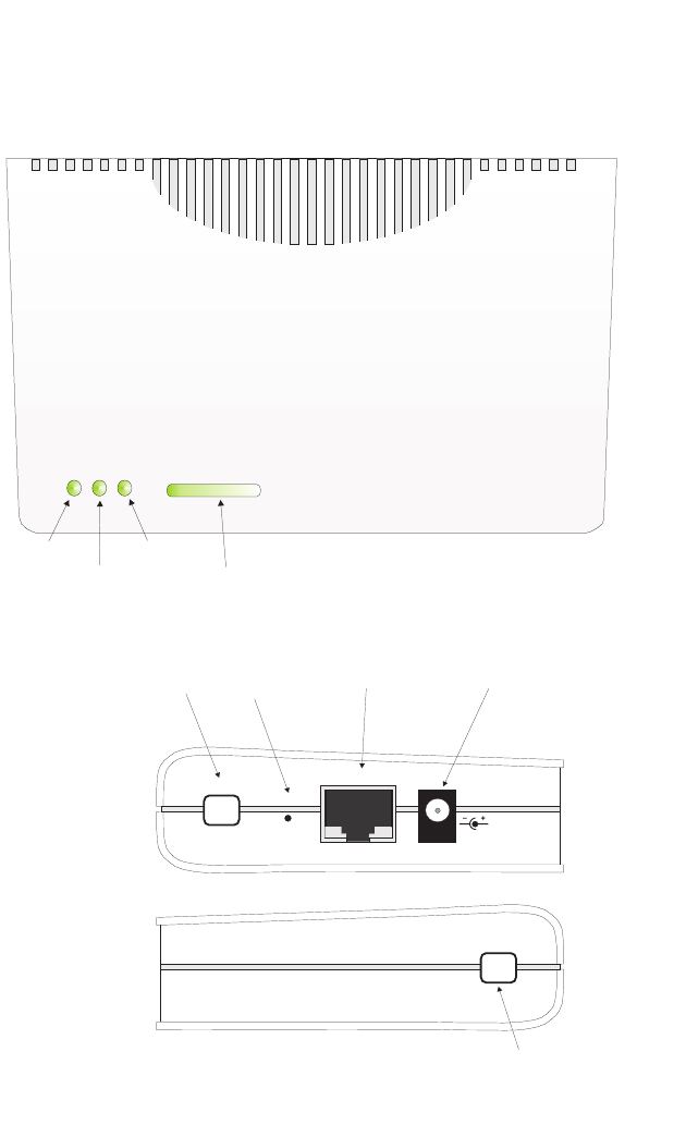
Top Panel
Side Panels
Traffic Rate
Power
WLAN
WAN
Power LED
WLAN LED
WAN LED
Traffic Rate LED
DC5V
WAN
Reset
ANT
External Antenna Connector
(not currently implemented) Rest Button 10/100 Ethernet
Port Power Socket
ANT
External Antenna Connector
(not currently implemented)
Introduction
1-4
Component Description
Antennas
The access point includes integrated internal diversity antennas for wireless
comunications. A diversity antenna system uses two identical antennas to receive
and transmit signals, helping to avoid multipath fading effects. When receiving, the
access point checks both antennas and selects the one with the strongest signal.
When transmitting, it will continue to use the antenna previously selected for
receiving. The access point never transmits from both antennas at the same time.
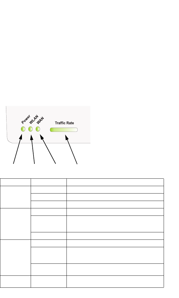
LED Indicators
The access point includes four status LED indicators, as described in the following
figure and table.
LED Status Description
Power On Green Indicates that the system is working normally
Flashing Green System running its power-on-self-test
On Amber Indicates system errors
WLAN On Green Indicates the 802.11g radio is enabled.
Flashing Green Indicates that the access point is transmitting or receiving
data through wireless links. Flashing rate is proportional
to network activity.
Off Indicates the 802.11g radio is disabled.
WAN On Green Indicates a valid link on the Ethernet port.
Flashing Green Indicates that the access point is transmitting or receiving
data through the Ethernet port. Flashing rate is
proportional to network activity.
Off The Ethernet port has no link or is administratively
disabled.
Traffic Rate On or Flashing
Green Indicates the level of wireless activity ranging from 0% to
100% of bandwidth utilization.
Power 802.11g
Wireless
Link/Activity
Traffic Rate
Ethernet
Link/Activity

Hardware Description
1-5
Ethernet Port
The access point has one 10BASE-T/100BASE-TX RJ-45 port that can be attached
directly to 10BASE-T/100BASE-TX LAN segments. These segments must conform
to the IEEE 802.3 or 802.3u specifications.
This port supports automatic MDI/MDI-X operation, so you can use straight-through
cables for all network connections to PCs, switches, or hubs.
The access point appears as an Ethernet node and performs a bridging function by
moving packets from the wired LAN to remote workstations on the wireless
infrastructure.
Note: The RJ-45 port also supports Power over Ethernet (PoE) based on the IEEE
802.3af standard. Refer to the description for the “Power Connector” for
information on supplying power to the access point’s network port from a
network device, such as a switch, that provides Power over Ethernet (PoE).
Reset Button
This button is used to reset the access point or restore the factory default
configuration. If you hold down the button for less than 5 seconds, the access point
will perform a hardware reset. If you hold down the button for 5 seconds or more,
any configuration changes you may have made are removed, and the factory default
configuration is restored to the access point.
Power Connector
The access point does not have a power switch. It is powered on when connected to
the AC power adapter, and the power adapter is connected to a power source. The
power adapter automatically adjusts to any voltage between 100-240 volts at 50 or
60 Hz. No voltage range settings are required.
The access point may also receive Power over Ethernet (PoE) from a switch or
other network device that supplies power over the network cable based on the IEEE
802.3af standard.
Note that if the access point is connected to a PoE source device and also
connected to a local power source through the AC power adapter, PoE will be
disabled.

Introduction
1-6
2-1
Chapter 2: Hardware Installation
1. Select a Site – Choose a proper place for the access point. In general, the best
location is at the center of your wireless coverage area, within line of sight of all
wireless devices. Try to place the access point in a position that can best cover
its Basic Service Set (refer to “Infrastructure Wireless LAN” on page 3-2). For
optimum performance, consider these points:
• Mount the access point as high as possible above any obstructions in the
coverage area.
• Avoid mounting next to or near building support columns or other obstructions
that may cause reduced signal or null zones in parts of the coverage area.
• Mount away from any signal absorbing or reflecting structures (such as those
containing metal).
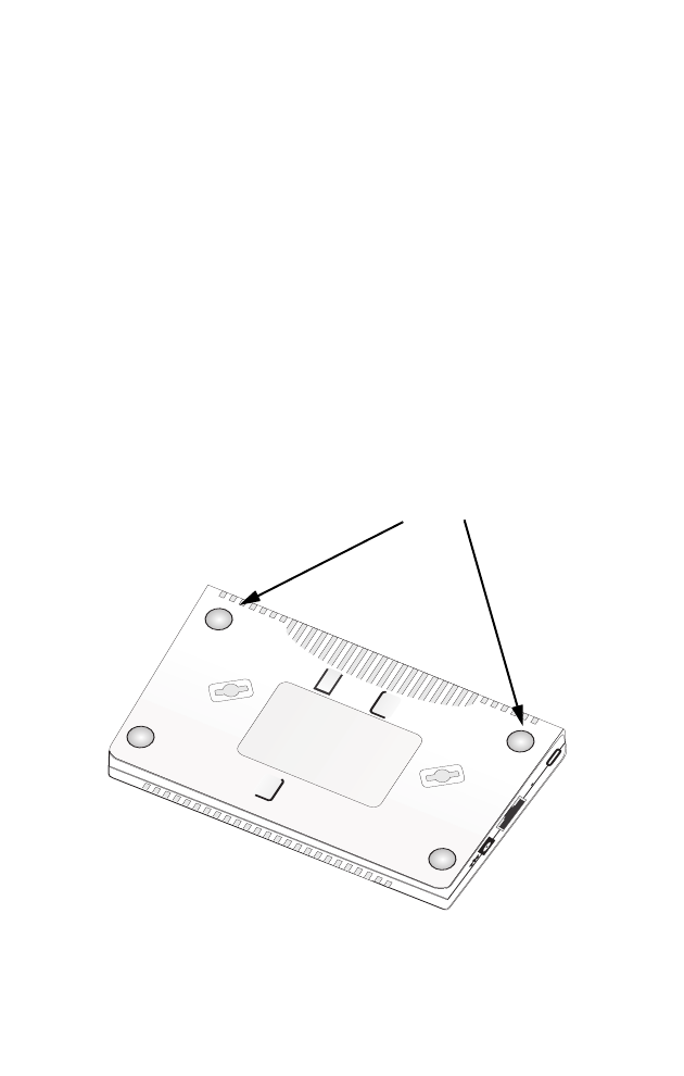
2. Mount the Access Point – The access point can be mounted on any
horizontal surface, wall or suspended ceiling.
Mounting on a horizontal surface – The four attached rubber feet keep the
access point from sliding on smooth surfaces.
DC5V
WAN
Reset
ANT
Rubber Feet
Bottom of Access Point
Hardware Installation
2-2
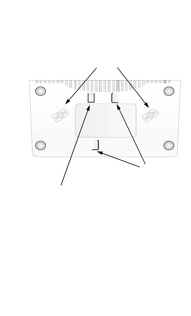
Mounting on a wall – The access point should be mounted only to a wall or
wood surface that is at least 1/2-inch plywood or its equivalent. Mark the
position of the mounting screws on the wall so they line up with the two
mounting slots on the bottom of the access point. Set the 5/8-inch number 12
wood screws into the wall, leaving about 3 mm (0.12 in.) clearance from the
wall. And then slide the access point down onto the screws.
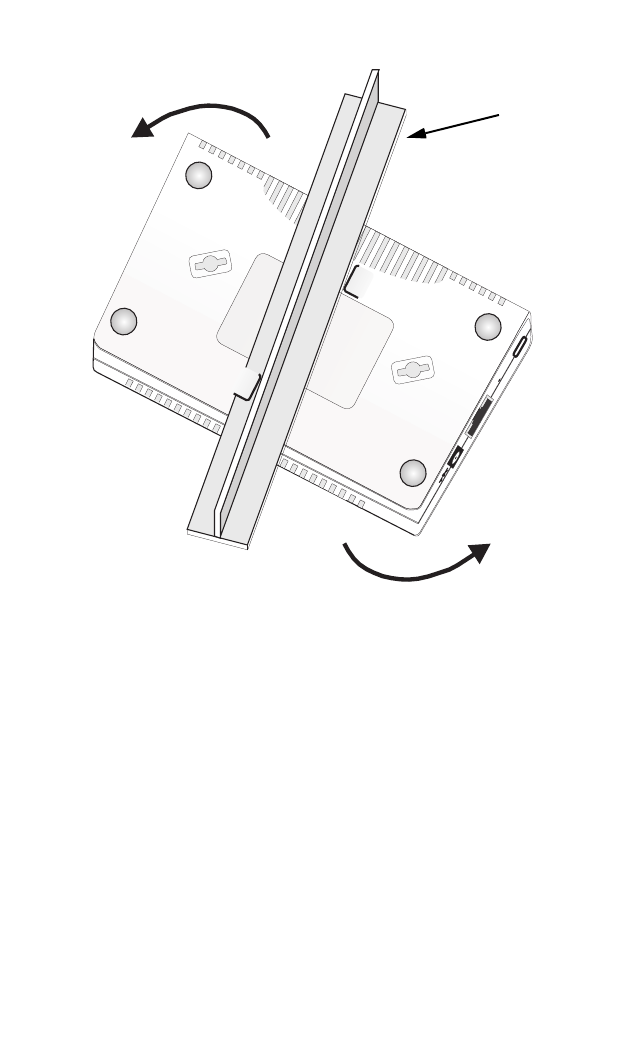
Mounting on a suspended ceiling – To mount the access point to a suspended
ceiling, do the following:
• Choose a location on the ceiling where the access point will be installed on the
suspended ceiling T-rail.
• Align the mounting track and fastening clip with the T-rail and slide sideways
so that the T-rail engages with the second mounting track. The access point
will snap into place.
Wall Mounting Slots
Bottom of Access Point
Fastening Clip
T-rail Mounting Tracks
2-3
3. Connect the Power Cord – Connect the power adapter to the access point,
and the power cord to an AC power outlet.
Note: If the access point is connected to both a PoE source device and an AC power
source, PoE will be disabled.
Caution: Use ONLY the power adapter supplied with this access point. Otherwise, the
product may be damaged.
4. Observe the Self Test – When you power on the access point, verify that the
Power indicator stops flashing and remains on, and that the other indicators
start functioning as described under “LED Indicators” on page 1-4. If the Power
LED turns on amber, the self test has not completed correctly. Refer to
“Troubleshooting” on page A-1.
5. Connect the Ethernet Cable – The access point can be wired to a
10/100 Mbps Ethernet through a network device such as a hub or a switch.
Connect your network to the RJ-45 port on the back panel with category 3, 4, or
5 UTP Ethernet cable. When the access point and the connected device are
powered on, the WAN LED should turn on indicating a valid network
connection. If the WAN LED fails to turn on refer to
“Troubleshooting” on page A-1.
DC5V
WAN
Reset
ANT
T-rail (ceiling mount)

Hardware Installation
2-4
Note: The RJ-45 port on the access point supports automatic MDI/MDI-X operation, so
you can use straight-through cables for all network connections to PCs, switches,
or hubs.
Access Point Configuration
The access point can be configured by connecting a PC to its Ethernet port and
accessing the web interface. The default IP address of the access point is
192.168.1.50, with default user name and password of ‘admin’.
For detailed information on configuring the access point refer to the Management
Guide.

3-1
Chapter 3: Network Configuration
Wireless networks support a stand-alone configuration as well as an integrated
configuration with 10/100 Mbps Ethernet LANs. The 2.4 GHz Wireless Access Point
also provides repeater and bridging services.
Access points can be deployed to support wireless clients and connect wired LANs
in the following configurations:
• Ad hoc for departmental, SOHO or enterprise LANs
• Infrastructure for wireless LANs
• Infrastructure wireless LAN for roaming wireless PCs
• Infrastructure wireless bridge to connect wired LANs
• Infrastructure wireless repeater for extended range
The 802.11b and 802.11g frequency band, which operates at 2.4 GHz, can easily
encounter interference from other 2.4 GHz devices, such as other 802.11b or g
wireless devices, cordless phones and microwave ovens. If you experience poor
wireless LAN performance, try the following measures:
• Limit any possible sources of radio interference within the service area
• Increase the distance between neighboring access points
• Decrease the signal strength of neighboring access points
• Increase the channel separation of neighboring access points (e.g. up to 3
channels of seperation for 802.11b, or up to 5 channels for 802.11g)
Network Configuration
3-2
Network Topologies
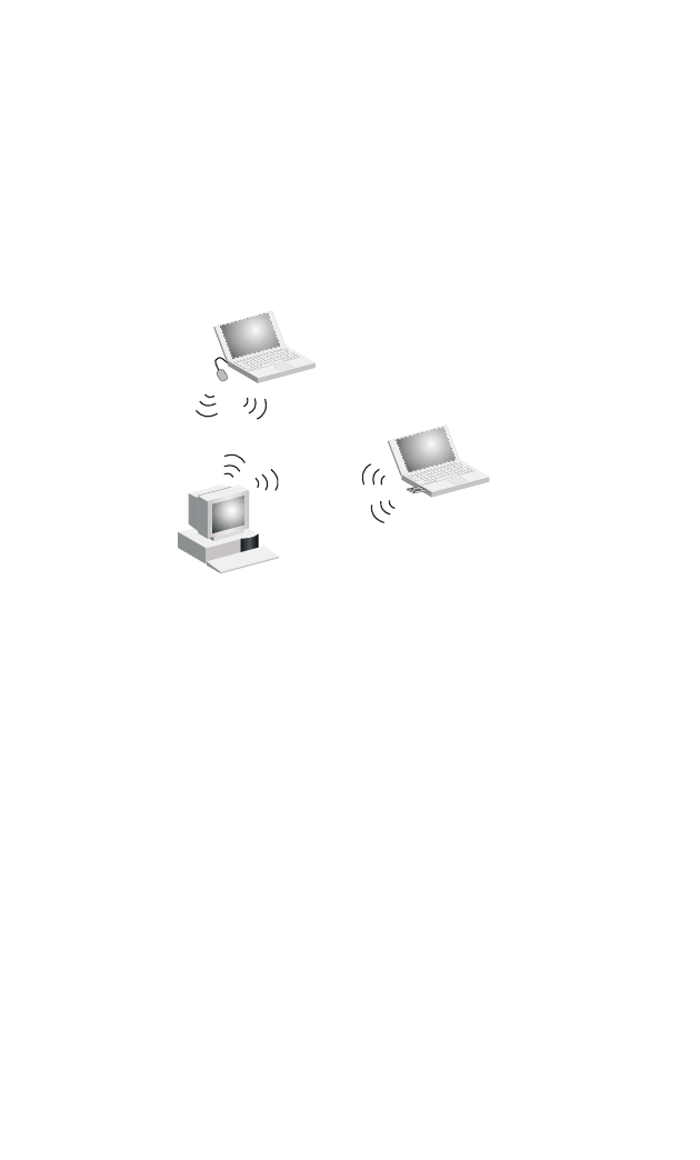
Ad Hoc Wireless LAN (no Access Point)
An ad hoc wireless LAN consists of a group of computers, each equipped with a
wireless adapter, connected via radio signals as an independent wireless LAN.
Computers in a specific ad hoc wireless LAN must therefore be configured to the
same radio channel. An ad hoc wireless LAN can be used for a branch office or
SOHO operation.
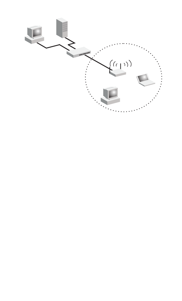
Infrastructure Wireless LAN
The access point also provides access to a wired LAN for wireless workstations. An
integrated wired/wireless LAN is called an Infrastructure configuration. A Basic
Service Set (BSS) consists of a group of wireless PC users, and an access point
that is directly connected to the wired LAN. Each wireless PC in this BSS can talk to
any computer in its wireless group via a radio link, or access other computers or
network resources in the wired LAN infrastructure via the access point.
The infrastructure configuration not only extends the accessibility of wireless PCs to
the wired LAN, but also increases the effective wireless transmission range for
wireless PCs by passing their signal through one or more access points.
A wireless infrastructure can be used for access to a central database, or for
connection between mobile workers, as shown in the following figure.
Ad Hoc Wireless LAN
Notebook with
Wireless USB Adapter
Notebook with
Wireless PC Card
PC with Wireless
PCI Adapter
Network Topologies
3-3
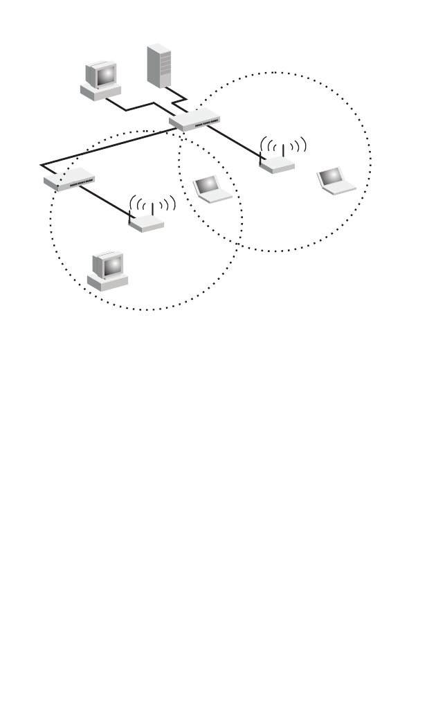
Infrastructure Wireless LAN for Roaming Wireless PCs
The Basic Service Set (BSS) defines the communications domain for each access
point and its associated wireless clients. The BSS ID is a 48-bit binary number
based on the access point’s wireless MAC address, and is set automatically and
transparently as clients associate with the access point. The BSS ID is used in
frames sent between the access point and its clients to identify traffic in the service
area.
The BSS ID is only set by the access point, never by its clients. The clients only
need to set the Service Set Identifier (SSID) that identifies the service set provided
by one or more access points. The SSID can be manually configured by the clients,
can be detected in an access point’s beacon, or can be obtained by querying for the
identity of the nearest access point. For clients that do not need to roam, set the
SSID for the wireless card to that used by the access point to which you want to
connect.
A wireless infrastructure can also support roaming for mobile workers. More than
one access point can be configured to create an Extended Service Set (ESS). By
placing the access points so that a continuous coverage area is created, wireless
users within this ESS can roam freely. All wireless network cards and adapters and
wireless access points within a specific ESS must be configured with the same
SSID.
Server
Switch
Desktop PC
Access Point
Wired LAN Extension
to Wireless Clients
Desktop PC
Notebook PC
Network Configuration
3-4
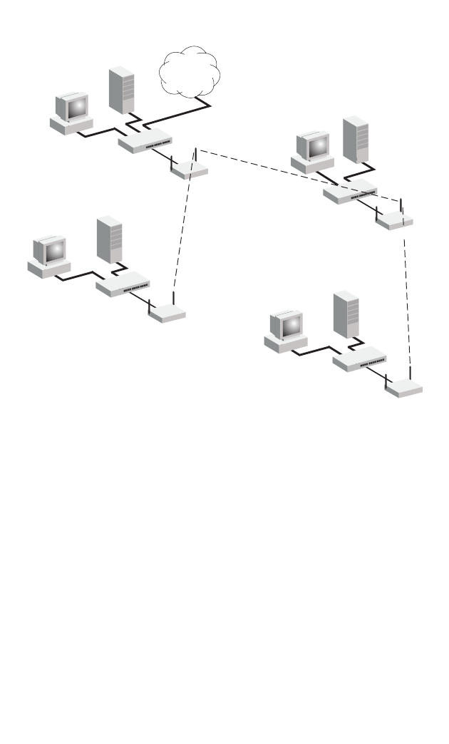
Infrastructure Wireless Bridge
The IEEE 802.11 standard defines a WIreless Distribution System (WDS) for bridge
connections between BSS areas (access points). The access point uses WDS to
forward traffic on links between units.
Up to six WDS bridge links can be specified for each unit in the wireless bridge
network. One unit only must be configured as the “root bridge” in the wireless
network. The root bridge should be the unit connected to the main core of the wired
LAN. Other bridges must configure one “parent” link to the root bridge or to a bridge
connected to the root bridge. The other five available WDS links can be specified as
“child” links to other bridges. This forms a tiered-star topology for the wireless bridge
network.
When using WDS on the access point radio, only wireless bridge units can associate
to each other. Wireless clients can only associate with the access point when the
radio is set to access point or repeater mode.
<BSS 2>
<ESS>
<BSS 1>
Server
Switch
Desktop PC
Access Point
Seamless Roaming
Between Access Points
Desktop PC
Notebook PC
Access Point
Notebook PC
Switch
Network Topologies
3-5
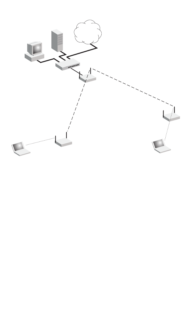
Infrastructure Wireless Repeater
The access point can also operate in a bridge “repeater” mode to extend the range
of links to wireless clients. The access point uses WDS to forward traffic between
the repeater bridge and the root bridge. The access point supports up to six WDS
repeater links.
In repeater mode, the access point does not support an Ethernet link to a wired LAN.
Note that when the access point operates in this mode only half the normal
throughput is possible. This is because the access point has to receive and then
re-transmit all data on the same channel.
Wireless Bridge Links
Between Access Points
Root Bridge
Bridge
Bridge
Bridge
Network
Core
Network Configuration
3-6
Wireless Repeater Links
Between Access Points
802.11g Radio
Repeater Link
802.11g Radio
Repeater Link
802.11g Radio
AP Link
802.11g Radio
AP Link
Root Bridge
Repeater
Network
Core
Repeater

A-1
Appendix A: Troubleshooting
Diagnosing Access Point Indicators
Note: For information on troubleshooting wireless connectivity issues, refer to the
Management Guide.
Troubleshooting Chart
Symptom Action
Power LED is Off • AC power adapter may be disconnected. Check connections between
the access point, the power adapter, and the wall outlet.
• PoE power to the access point may be disabled at the connected
switch port. Check the switch configuration to be sure that PoE power
is enabled for the switch and specified port. Also check that the switch
has not exceeded its power budget and turned off the port power.
Power LED is Amber • The access point has detected a system error. Reboot the access
point to try and clear the condition.
• If the condition does not clear, contact your local dealer for assistance.
WAN LED is Off • Verify that the access point and attached device are powered on.
• Be sure the cable is plugged into both the access point and
corresponding device.
• Verify that the proper cable type is used and its length does not exceed
specified limits.
• Check the cable connections for possible defects. Replace the
defective cable if necessary.

Troubleshooting
A-2
B-1
Appendix B: Cables and Pinouts
Twisted-Pair Cable Assignments
For 10/100BASE-TX connections, a twisted-pair cable must have two pairs of wires.
Each wire pair is identified by two different colors. For example, one wire might be
green and the other, green with white stripes. Also, an RJ-45 connector must be
attached to both ends of the cable.
Caution: Each wire pair must be attached to the RJ-45 connectors in a specific
orientation. (See “Straight-Through Wiring” on page B-2 and “Crossover
Wiring” on page B-3 for an explanation.)
Caution: DO NOT plug a phone jack connector into the RJ-45 port. Use only twisted-pair
cables with RJ-45 connectors that conform with FCC standards.
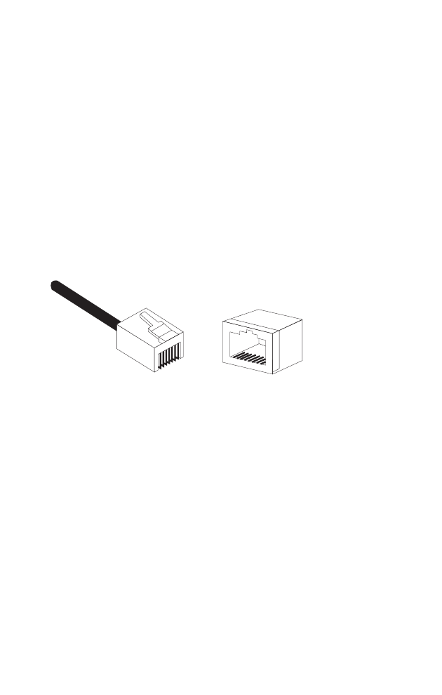
The following figure illustrates how the pins on the RJ-45 connector are numbered.
Be sure to hold the connectors in the same orientation when attaching the wires to
the pins.
10/100BASE-TX Pin Assignments
Use unshielded twisted-pair (UTP) or shielded twisted-pair (STP) cable for RJ-45
connections: 100-ohm Category 3 or better cable for 10 Mbps connections, or
100-ohm Category 5 or better cable for 100 Mbps connections. Also be sure
that the
length of any twisted-pair connection does not exceed 100 meters (328 feet).
The RJ-45 port on the access point supports automatic MDI/MDI-X operation, so
you can use straight-through or crossover cables for all network connections to PCs,
switches, or hubs. In straight-through cable, pins 1, 2, 3, and 6, at one end of the
cable, are connected straight through to pins 1, 2, 3, and 6 at the other end of the
cable.
1
88
1
Cables and Pinouts
B-2
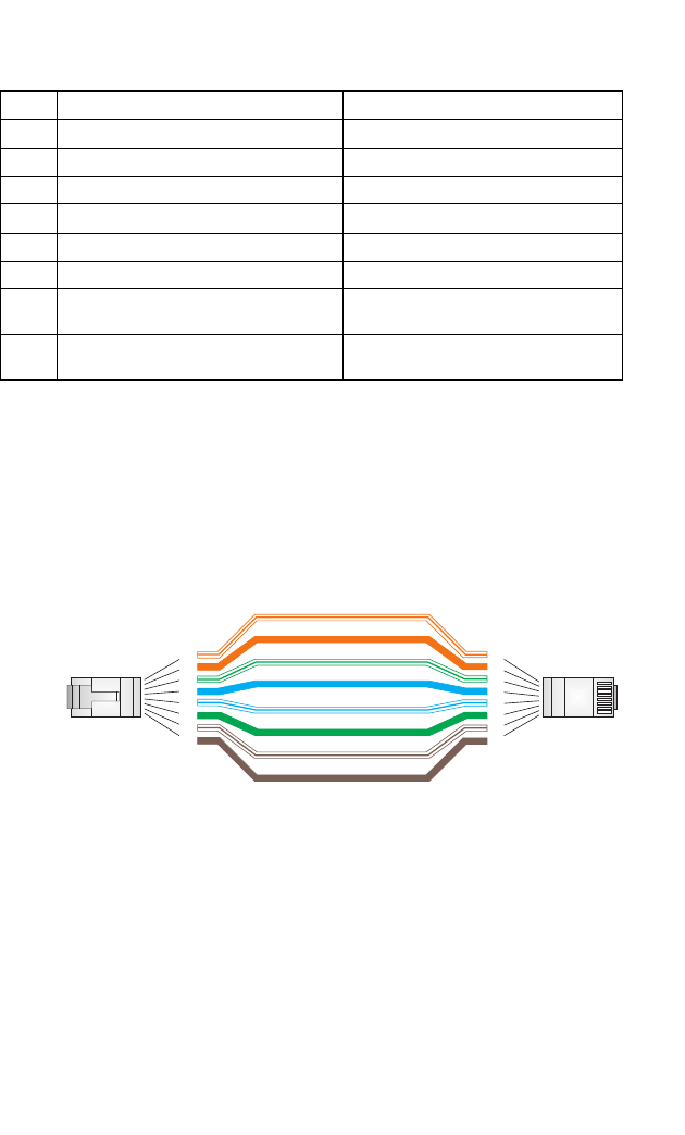
Straight-Through Wiring
If the twisted-pair cable is to join two ports and only one of the ports has an internal
crossover (MDI-X), the two pairs of wires must be straight-through.
Pin MDI Signal Name MDI-X Signal Name
1 Transmit Data plus (TD+) Receive Data plus (RD+)
2 Transmit Data minus (TD-) Receive Data minus (RD-)
3 Receive Data plus (RD+) Transmit Data plus (TD+)
4 GND (Positive Vport) GND (Positive Vport)
5 GND (Positive Vport) GND (Positive Vport)
6 Receive Data minus (RD-) Transmit Data minus (TD-)
7 -48V feeding power
(Negative- Vport) -48V feeding power
(Negative- Vport)
8 -48V feeding power
(Negative- Vport) -48V feeding power
(Negative- Vport)
Note: The “+” and “-” signs represent the polarity of the wires that make up each wire pair.
White/Orange Stripe
Orange
White/Green Stripe
Green
1
2
3
4
5
6
7
8
1
2
3
4
5
6
7
8
EIA
/
TIA 568B RJ-45 Wiring
S
tandard
10/100BASE-TX Straight-through Cable
End A End B
Blue
White/Blue Stripe
Brown
White/Brown Stripe

Twisted-Pair Cable Assignments
B-3
Crossover Wiring
If the twisted-pair cable is to join two ports and either both ports are labeled with an
“X” (MDI-X) or neither port is labeled with an “X” (MDI), a crossover must be
implemented in the wiring.
White/Orange Stripe
Orange
White/Green Stripe
1
2
3
4
5
6
7
8
1
2
3
4
5
6
7
8
EIA
/
TIA 568B RJ-45 Wiring
S
tandard
10/100BASE-TX Crossover Cable
End A End B
Green
Blue
White/Blue Stripe
Brown
White/Brown Stripe

Cables and Pinouts
B-4

C-1
Appendix C: Specifications
General Specifications
Maximum Channels
802.11b/g:
FCC/IC: 1-11
ETSI: 1-13
France: 10-13
MKK: 1-14
Taiwan: 1-11
Maximum Clients
64 per VAP interface
Data Rate
802.11g: 6, 9, 11, 12, 18, 24, 36, 48, 54 Mbps per channel
802.11b: 1, 2, 5.5, 11 Mbps per channel
Modulation Type
802.11g: CCK, BPSK, QPSK, OFDM
802.11b: CCK, BPSK, QPSK
Network Configuration
Infrastructure
Operating Frequency
802.11b:
2.4 ~ 2.4835 GHz (US, Canada, ETSI)
2.4 ~ 2.497 GHz (Japan)
2.400 ~ 2.4835 GHz (Taiwan)
AC Power Adapter
Input: 100-240 AC, 50-60 Hz
Output: 5 VDC, 2A
Maximum Power: 13.2 Watts
Unit Power Supply
DC Input: 5 VDC, 2 A maximum
PoE input: -48 VDC, 0.27 A maximum
Power Consumption: 9.6 W maximum
Physical Size
15.6 x 11.7 x 2.8 cm (6.14 x 4.6 x 1.1 in)

Specifications
C-2
Weight
0.205 kg (0.44 lbs)
LED Indicators
PWR (Power), WAN (Ethernet Link/Activity), WLAN (802.11b/g Wireless Link/
Activity), Traffic Rate (Wireless LAN bandwidth utilization)
Network Management
Web-browser, SNMP
Temperature
Operating: 0 to 55 °C (32 to 131 °F)
Storage: 0 to 70 °C (32 to 158 °F)
Humidity
15% to 95% (non-condensing)
Compliances
FCC Part 15B Class B
Radio Signal Certification
FCC Part 15C 15.247, 15.207 (2.4 GHz)
Safety
CSA/C US (CSA60950-1 & UL60950-1)
IEC60950-1 (CB)
Standards
IEEE 802.3 10BASE-T, IEEE 802.3u 100BASE-TX,
IEEE 802.11b, g

General Specifications
C-3
Sensitivity
Transmit Power
IEEE 802.11g
Data Rate Sensitivity (dBm)
6 Mbps -88
9 Mbps -87
12 Mbps -86
17 Mbps -85
24 Mbps -81
36 Mbps -77
48 Mbps -72
54 Mbps -70
IEEE 802.11b
Data Rate Sensitivity (dBm)
1 Mbps -93
2 Mbps -90
5.5 Mbps -90
11 Mbps -87
IEEE 802.11g Maximum Output Power (GHz - dBm)
Data Rate 2.412 2.417~2.467 2.472
6 Mbps 20 20 18
9 Mbps 20 20 18
12 Mbps 20 20 18
18 Mbps 20 20 18
24 Mbps 20 20 18
36 Mbps 18 19 17
48 Mbps 17 16 15
54 Mbps 15 14 13

Specifications
C-4
Operating Range
Note: The operating range distances listed in the following tables are for typical
environments only. Operating ranges can vary considerably depending on
factors such as local interference and barrier composition. It is recommended
to do a site survey to determine the maximum ranges for specific access point
locations in your environment.
IEEE 802.11b Maximum Output Power (GHz - dBm)
Data Rate 2.412 2.417~2.467 2.472
1 Mbps 15 16 15
2 Mbps 15 16 15
5.5 Mbps 15 16 15
11 Mbps 15 16 15
802.11g Wireless Distance Table
Speed and Distance Ranges
54
Mbps 48
Mbps 36
Mbps 24
Mbps 18
Mbps 12
Mbps 11
Mbps 9
Mbps 6
Mbps 5
Mbps 2
Mbps 1
Mbps
LoS1148 m
485 ft 235 m
771 ft 415 m
136 ft 500 m
1640 ft 522 m
1712 ft 570 m
1870 ft 620 m
2034 ft 650 m
2132 ft 680 m
2230 ft 780 m
2558 ft 782 m
2565 ft 790 m
2591 ft
Non-LoS243 m
141 ft 50 m
164 ft 57 m
187 ft 63 m
207 ft 67 m
220 ft 71 m
233 ft 75 m
246 ft 77 m
253 ft 81 m
266 ft 85 m
279 ft 85 m
279 ft 85 m
279ft
1. A line-of-sight (LoS) environment with no obstructions between the access point and clients.
2. A typical non-LoS environment (office or home) with floor to ceiling obstructions between the access point
and clients.
802.11b Wireless Distance Table
Speed and Distance Ranges
11 Mbps 5.5 Mbps 2 Mbps 1 Mbps
LoS1578 m
1896 ft
617 m
2024 ft
694 m
2276 ft
875 m
2870 ft
Non-LoS270 m
230 ft
75 m
246 ft
85 m
279 ft
85 m
279 ft
1. A line-of-sight (LoS) environment with no obstructions between the access point and clients.
2. A typical non-LoS environment (office or home) with floor to ceiling obstructions between the access point
and clients.
Model Number: EAP2316A
Pub. Number: 150200023800E, E072005-R01