Accton Technology ECG9210 VDSL2 Gateway User Manual install
Accton Technology Corp VDSL2 Gateway install
User Manual

http://www.edgecorenetworks.com
User Guide
http://www.edgecorenetwork
s
ECG9210-04
Home Gateway VDSL2
Router with 802.11b/g
capabilities


User Guide
Home Gateway VDSL2 Router
VDSL2 Home Gateway Router with
4100BASE-TX (RJ-45) Ports, 2 VDSL Ports (RJ-11)
and 802.11b/g wireless capabilities
EGC9210-04
E022010-DT-R01
150200000095A

v
Compliances
FCC - Class B
This equipment has been tested and found to comply with the limits for a Class B
digital device, pursuant to Part 15 of the FCC Rules. These limits are designed to
provide reasonable protection against harmful interference in a residential installation.
This equipment generates, uses and can radiate radio frequency energy and, if not
installed and used in accordance with instructions, may cause harmful interference to
radio communications. However, there is no guarantee that the interference will not
occur in a particular installation. If this equipment does cause harmful interference to
radio or television reception, which can be determined by turning the equipment off
and on, the user is encouraged to try to correct the interference by one or more of the
following measures:
• Reorient the receiving antenna
• Increase the separation between the equipment and receiver
• Connect the equipment into an outlet on a circuit different from that to which the
receiver is connected
• Consult the dealer or an experienced radio/TV technician for help
You are cautioned that changes or modifications not expressly approved by the party
responsible for compliance could void your authority to operate the equipment.
You may use unshielded twisted-pair (UTP) for RJ-45 connections - Category 3 or
better for 10 Mbps connections, or Category 5 or better for 100 Mbps connections.
This device complies with Part 15 of the FCC Rules. Operation is subject to the
following two conditions: (1) This device may not cause harmful interference, and (2)
this device must accept any interference received, including interference that may
cause undesired operation.
For product available in the USA/Canada market, only channel 1~11 can be operated.
Selection of other channels is not possible.
This device and its antenna(s) must not be co-located or operation in conjunction with
any other antenna or transmitter.
IMPORTANT NOTE:
FCC Radiation Exposure Statement:
This equipment complies with FCC radiation exposure limits set forth for an
uncontrolled environment. This equipment should be installed and operated with
minimum distance 20cm between the radiator & your body.
EC Conformance Declaration
Marking by the above symbol indicates compliance with the Essential Requirements of the
R&TTE Directive of the European Union (1999/5/EC). This equipment meets the following
conformance standards:
• EN 60950-1 (IEC 60950-1) - Product Safety

vi
• EN 300 328 - Technical requirements for 2.4 GHz radio equipment
• EN 301 489-1 / EN 301 489-17 - EMC requirements for radio equipment
This device is intended for use in the following European Community and EFTA countries:
Requirements for indoor vs. outdoor operation, license requirements and allowed channels
of operation apply in some countries as described below:
• In Italy the end-user must apply for a license from the national spectrum authority to
operate this device outdoors.
• In Belgium outdoor operation is only permitted using the 2.46 - 2.4835 GHz band:
Channel 13.
• In France outdoor operation is only permitted using the 2.4 - 2.454 GHz band:
Channels 1 - 7.
Note: The user must use the configuration utility provided with this product to ensure the
channels of operation are in conformance with the spectrum usage rules for
European Community countries as described below.
• This device will automatically limit the allowable channels determined by the current
country of operation. Incorrectly entering the country of operation may result in illegal
operation and may cause harmful interference to other systems. The user is obligated to
ensure the device is operating according to the channel limitations, indoor/outdoor
restrictions and license requirements for each European Community country as described
in this document.
• This device may be operated indoors only in all countries of the European Community
using the 2.4 GHz band: Channels 1 - 13, except where noted below.
• In Italy the end-user must apply for a license from the national spectrum authority to
operate this device outdoors.
• In Belgium outdoor operation is only permitted using the 2.46 - 2.4835 GHz band:
Channel 13.
• In France outdoor operation is only permitted using the 2.4 - 2.454 GHz band:
Channels 1 - 7.
Declaration of Conformity in Languages of the European Community:
Austria Belgium Cyprus Czech Republic Denmark
Estonia Finland France Germany Greece
Hungary Iceland Ireland Italy Latvia
Liechtenstein Lithuania Luxembourg Malta Netherlands
Norway Poland Portugal Slovakia Slovenia
Spain Sweden Switzerland United Kingdom
Czech
Česky
SMC tímto prohlašuje, že tento Radio LAN device je ve shodě se základními
požadavky a dalšími příslušnými ustanoveními směrnice 1999/5/ES.
Estonian
Eesti
Käesolevaga kinnitab SMC seadme Radio LAN device vastavust direktiivi
1999/5/EÜ põhinõuetele ja nimetatud direktiivist tulenevatele teistele
asjakohastele sätetele.

vii
English Hereby, SMC, declares that this Radio LAN device is in compliance with the
essential requirements and other relevant provisions of Directive 1999/5/
EC.
Finnish
Suomi
Valmistaja SMC vakuuttaa täten että Radio LAN device tyyppinen laite on
direktiivin 1999/5/EY oleellisten vaatimusten ja sitä koskevien direktiivin
muiden ehtojen mukainen.
Dutch
Nederlands
Hierbij verklaart SMC dat het toestel Radio LAN device in overeenstemming
is met de essentiële eisen en de andere relevante bepalingen van richtlijn
1999/5/EG
Bij deze SMC dat deze Radio LAN device voldoet aan de essentiële eisen
en aan de overige relevante bepalingen van Richtlijn 1999/5/EC.
French
Français
Par la présente SMC déclare que l'appareil Radio LAN device est conforme
aux exigences essentielles et aux autres dispositions pertinentes de la
directive 1999/5/CE
Swedish
Svenska
Härmed intygar SMC att denna Radio LAN device står I överensstämmelse
med de väsentliga egenskapskrav och övriga relevanta bestämmelser som
framgår av direktiv 1999/5/EG.
Danish
Dansk
Undertegnede SMC erklærer herved, at følgende udstyr Radio LAN device
overholder de væsentlige krav og øvrige relevante krav i direktiv 1999/5/EF
German
Deutsch
Hiermit erklärt SMC, dass sich dieser/diese/dieses Radio LAN device in
Übereinstimmung mit den grundlegenden Anforderungen und den anderen
relevanten Vorschriften der Richtlinie 1999/5/EG befindet". (BMWi)
Hiermit erklärt SMC die Übereinstimmung des Gerätes Radio LAN device
mit den grundlegenden Anforderungen und den anderen relevanten
Festlegungen der Richtlinie 1999/5/EG. (Wien)
Greek
Ελληνική
με την παρουσα SMC δηλωνει οτι radio LAN device συμμορφωνεται προσ
τισ ουσιωδεισ απαιτησεισ και τισ λοιπεσ σχετικεσ διαταξεισ τησ οδηγιασ
1999/5/εκ.
Hungarian
Magyar
Alulírott, SMC nyilatkozom, hogy a Radio LAN device megfelel a vonatkozó
alapvetõ követelményeknek és az 1999/5/EC irányelv egyéb elõírásainak.
Italian
Italiano
Con la presente SMC dichiara che questo Radio LAN device è conforme ai
requisiti essenziali ed alle altre disposizioni pertinenti stabilite dalla direttiva
1999/5/CE.
Latvian
Latviski
Ar šo SMC deklarē, ka Radio LAN device atbilst Direktīvas 1999/5/EK
būtiskajām prasībām un citiem ar to saistītajiem noteikumiem.
Lithuanian
Lietuvių
Šiuo SMC deklaruoja, kad šis Radio LAN device atitinka esminius
reikalavimus ir kitas 1999/5/EB Direktyvos nuostatas.
Maltese
Malti
Hawnhekk, SMC, jiddikjara li dan Radio LAN device jikkonforma mal-ħtiġijiet
essenzjali u ma provvedimenti oħrajn relevanti li hemm fid-Dirrettiva 1999/
5/EC.

viii
Customer Information
1. This equipment complies with Part 68 of the FCC rules and the requirements
adopted by the ACTA. On bottom of this equipment is a label that contains,
among other information, a product identifier of [INSERT LABEL]. If requested,
this number must be provided to the telephone company.
2. If this equipment, ECG9210-04, causes harm to the telephone network, the
telephone company will notify you in advance that temporary discontinuance of
service may be required. But if advance notice isn't practical, the telephone
company will notify the customer as soon as possible. Also you will be advised of
your right to file a complaint with the FCC if you believe it is necessary.
3. The telephone company may make changes in its facilities, equipment, operations
or procedures that could affect the operation of the equipment. If this happens, the
telephone company will provide advance notice in order for you to make
necessary modification to maintain uninterrupted service.
4. If you experience trouble with this equipment, you disconnect it from the network
until the problem has been corrected or until you are sure that the equipment is
not malfunctioning.
5. Please follow instructions for repairing if any (e.g. battery replacement section);
otherwise do not alternate or repair any parts of device except specified.
6. Connection to party line service is subject to state tariffs. Contact the state public
utility commission, public service commission or corporation commission for
information.
7. If your home has specially wired alarm equipment connected to the telephone
line, ensure the installation of this equipment does not disable alarm equipment,
consult your telephone company or a qualified installer.
Spanish
Español
Por medio de la presente SMC declara que el Radio LAN device cumple con
los requisitos esenciales y cualesquiera otras disposiciones aplicables o
exigibles de la Directiva 1999/5/CE
Polish
Polski
Niniejszym SMC oświadcza, że Radio LAN device jest zgodny z
zasadniczymi wymogami oraz pozostałymi stosownymi postanowieniami
Dyrektywy 1999/5/EC.
Portuguese
Português
SMC declara que este Radio LAN device está conforme com os requisitos
essenciais e outras disposições da Directiva 1999/5/CE.
Slovak
Slovensky
SMC týmto vyhlasuje, že Radio LAN device spĺňa základné požiadavky a
všetky príslušné ustanovenia Smernice 1999/5/ES.
Slovenian
Slovensko
SMC izjavlja, da je ta radio LAN device v skladu z bistvenimi zahtevami in
ostalimi relevantnimi določili direktive 1999/5/ES.

ix
Warnings and Cautionary Messages
Environmental Statement
The manufacturer of this product endeavours to sustain an environmentally-friendly policy
throughout the entire production process. This is achieved though the following means:
• Adherence to national legislation and regulations on environmental production standards.
• Conservation of operational resources.
• Waste reduction and safe disposal of all harmful un-recyclable by-products.
• Recycling of all reusable waste content.
• Design of products to maximize recyclables at the end of the product’s life span.
• Continual monitoring of safety standards.
End of Product Life Span
This product is manufactured in such a way as to allow for the recovery and disposal of all
included electrical components once the product has reached the end of its life.
Manufacturing Materials
There are no hazardous nor ozone-depleting materials in this product.
Documentation
All printed documentation for this product uses biodegradable paper that originates from
sustained and managed forests. The inks used in the printing process are non-toxic.
Warning: This product does not contain any serviceable user parts.
Caution: Do not plug a phone jack connector in the RJ-45 port. This may damage this
device.
Caution: Use only twisted-pair cables with RJ-45 connectors that conform to FCC
standards.

x

xi
About This Guide
Purpose
This guide details the hardware features of the Gateway, including its physical and
performance-related characteristics, and how to install the Gateway. It also includes
information on how to operate and use the management functions of the Gateway.
Audience
The guide is intended for use by network administrators who are responsible for installing
and setting up network equipment; consequently, it assumes a basic working knowledge
of LANs (Local Area Networks).
Conventions
The following conventions are used throughout this guide to show information:
Note: Emphasizes important information or calls your attention to related features or
instructions.
Caution: Alerts you to a potential hazard that could cause loss of data, or damage the
system or equipment.
Warning: Alerts you to a potential hazard that could cause personal injury.
Revision History
This section summarizes the changes in each revision of this guide.
January 2010 Revision
This is the first revision of this guide.

xii

xiii
Contents
Chapter 1: Introduction 13
Overview 13
VDSL Technology 14
Features and Benefits 15
Description of Hardware 16
Chapter 2: Installation 25
Installation Overview 25
Package Contents 25
System Requirements 25
Cable Connections 26
Powering On 27
Configuring the TCP/IP Protocols 27
Chapter 3: Network Planning 29
Application Examples 29
Networking Concepts 29
Route Determination 29
Bridging 29
Routing 30
Network Applications 30
Accessing a Remote Site 30
Accessing the Internet 31
Network Services 32
DHCP Service 32
DNS Service 32
NAT Functions 32
Virtual Server 33
User-Definable Application Sensing Tunnel 33
DMZ Host Support 33
Security 33
Virtual Private Network 34
Chapter 4: Initial Configuration 35
Accessing the Setup Wizard 35
Using the Setup Wizard 36
Chapter 5: System Configuration 45
Using the Web Interface 45
Home Page 46
Advanced Settings Menu 47
Status Information 50
System Information 50

Contents
xiv
WAN Status 51
Bridge WAN Status 52
LAN Status 52
System Log 53
DHCP Client List 53
System Configuration 54
System Mode 54
System Time 56
Admin Settings 57
System Tools 58
UPnP 59
Service Settings 60
SNMP 61
DNS 63
Management IP 63
WAN Configuration 64
WAN Type 64
WAN Settings 65
Dynamic IP Address 65
Static IP Address 66
PPPoE 67
DDNS 68
LAN Configuration 69
LAN Type 69
LAN Settings 70
Switch Ports 72
Route Configuration 73
Static Routing 73
Dynamic Routing 74
Policy Routing 76
Wireless Configuration 77
WLAN Security 79
WEP Security 79
WPA2 Security 80
WPS Security 82
Access Control 84
Client List 85
NAT Configuration 86
Virtual Server 86
Port Mapping 87
DMZ 89
Firewall Configuration 90
Firewall Settings 90
IP Filtering 91
ALG Configuration 92

Contents
xv
Remote Control 93
Denial of Service 94
VDSL Configuration 95
VDSL Status and Rate Information 95
Performance Counters 98
SNR Information 99
DELT 100
IGMP Configuration 101
IGMP Settings 102
QoS Configuration 104
QoS Settings 104
Traffic Classification 105
DSCP to 802.1p Mapping 107
ACS Configuration 108
TR Settings 108
Appendix A: Troubleshooting 111
Diagnosing Gateway Indicators 111
If You Cannot Connect to the Internet 112
Problems Accessing the Management Interface 112
Appendix B: Cables 113
Twisted-Pair Cable and Pin Assignments 113
10BASE-T/100BASE-TX Pin Assignments 113
Straight-Through Wiring 114
Crossover Wiring 115
Cable Testing for Existing Category 5 Cable 115
RJ-11 Ports 116
Appendix C: Specifications 117
Physical Characteristics 117
Standards 118
Compliances 119
Wireless Characteristics 119
Glossary 121
Index 127

Contents
xvi

13
Chapter 1: Introduction
Overview
This device can serve as a key component in any Ethernet-over-VDSL2 data transport
system that consists of an end-user Gateway and a VDSL2 switch connected by
standard telephone cable. The VDSL connection delivers an Ethernet data link rated
up to both 100 Mbps downstream and 100 Mbps upstream (VDSL2 profile 30A), while
simultaneously supporting standard telephone services. The system can be deployed
in any multi-dwelling/multi-tenant environment (apartment blocks, hotels, or office
complexes) to provide both high-speed Internet access and telephone services without
any need for re-wiring. It also provides a built-in 802.11b/g access point for wireless
connectivity.
VDSL switches combine both the data and phone signals coming from your Internet
and telephone service providers, and pass these signals directly over standard
telephone wiring to multiple users in the same building. The Gateway is used to
separate these signals and pass them on to a customer’s computer and telephone
equipment.
The VDSL2 switch is typically located in a wiring closet or other central location of a
multi-dwelling/multi-tenant unit, campus, or enterprise. An Internet connection is
provided from the ISP to the customer’s building over fiber optic cable, running
Ethernet directly over a 1 to 10 Gbps connection. This kind of WAN connection is
referred to as Fiber To The Building (FTTB). Data signals entering a site are first
passed through an Ethernet switch that segregates the signals for individual user
connections, and are then fed into the switch. Phone signals are also routed from PBX/
MDF distribution equipment into the switch. The data and phone signals for each user
are combined in the switch, and passed over VDSL lines to individual customers.
The Gateway at the customer end of the VDSL line connects to any PC equipped with
a 10BASE-T or 100BASE-TX network interface card. Your existing telephone, modem,
or fax machine simply plugs into the Gateway’s phone port. There is no need for
splitters, terminators, or filters. In fact, there is no need to modify your home wiring at
all. And because the VDSL connection is based on Ethernet, no complex software
configuration is required.
The Gateway provides access to a wide range of advanced transport features,
including support for real-time video, and other multimedia services requiring
guaranteed Quality of Service (QoS). It also provides multiprotocol encapsulation for
bridging Windows NetBEUI and Novell’s IPX protocols directly to a remote site for
complete access to corporate resources, or for routing TCP/IP traffic for Internet
connections.
Introduction
14
1
VDSL Technology
VDSL (Very High Bit-Rate Digital Subscriber Line) is at the high-end of all the DSL
technologies, offering the best combination of fiber optics and copper to provide
high-speed broadband Internet access. VDSL’s primary application is in providing a
broadband data service to multi-tenant residential or commercial buildings. In this
implementation, fiber optic cable carries the data from a telephone company’s central
office to the building; then the installed telephone copper wires take the data and
deliver it to individual units within that building.
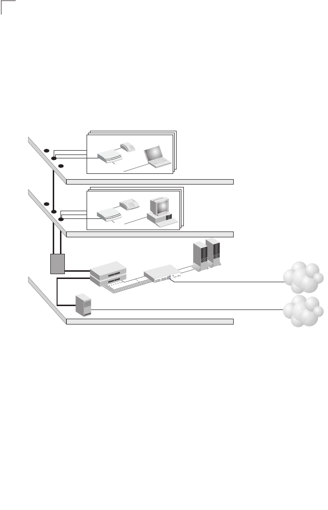
Figure 1-1 Providing Broadband Internet Access through VDSL
VDSL provides high-speed Internet access over existing phone lines by making use of
previously unused frequency bandwidth above the voice band (i.e., up to 30 MHz with
VDSL2). By placing VDSL signals above the frequency of the voice signal, a VDSL
service can coexist on the same line with other telephone services. VDSL can operate
symmetrically, providing the same data rate in both directions, or asymmetrically,
providing a higher data rate in the downstream (receive) direction than in the upstream
(transmit) direction.
VDSL delivers high-performance online applications, such as high-quality video and
other switched multimedia services. This Ethernet VDSL2 Gateway provides robust
performance, with a data rate up to 100 Mbps downstream and 100 Mbps upstream,
and a range up to 200 meters (656 ft).
This system is based on advanced VDSL2 Multi-Carrier Modulation (MCM) technology
with adaptive channel equalization that overcomes bridge taps and other line
ISP
(Internet)
Central Office
(PSTN)
Punch Down
Blocks /
Patch Panels
PBX
Telephone/Fax
Telephone
VDSL
Concentrators Ethernet
Switch
1
ES3526F
Telephone Line from Central Office
Fiber Optic Link to ISP
Local Servers
(Locally Hosted Services,
Video Servers, Billing)
Existing Phone
Lines to Clients
Multi-dwelling/Multi-tenant Building
Floor 2
Floor 1
Rooms/Clients
Rooms/Clients
VDSL Lines
Phone Lines
Ethernet
Links to Switch
VDSL Gateway
VDSL Gateway

Features and Benefits
15
1
distortions. Reed-Solomon Forward Error Correction and interleaving protects against
errors due to impulse noise, and enables recovery from signal interruptions. Frequency
Division Duplexing (FDD) separates downstream and upstream channels and allows
VDSL signals to coexist with regular telephone services. A power back-off mechanism
is also implemented to reduce noise from crosstalk in line bundles.
Features and Benefits
VDSL features (Gateway side) include:
• High-speed Internet access over existing phone lines
• VDSL2 connection provides the following rate/range options (profile 30A):
• Concurrent data and telephone services over a single connection
• Always-on digital connection eliminates dial-up delays, providing transparent
reconnection when initiating a network request
• Supports ITU-T VDSL2 and interface standards
• Spectral compatibility with VDSL2, Smartphone digital PBX extensions and
narrowband interference
• Robust operation on severely distorted lines
• Supports power back-off algorithm that permits a mixed distance deployment
• Wireless 802.11b/g access point
• LEDs indicate VDSL link status, and power
• Simple plug-and-play installation
Additional VDSL2 features (Gateway side) include:
• Fast startup for quick initialization
• Trellis coding modulation for higher performance
• Seamless rate adaptation for enhanced quality in video applications
• Variable tone spacing enables best performance for long and short reach lines
• Improved framing, overhead channel, and interleaving
Gateway services include:
• Multiprotocol encapsulation of Windows NetBEUI, Novell’s IPX and TCP/IP via
bridging for complete access to corporate resources
• TCP/IP routing transport using RIP or RIP 2 for Internet access
Table 1-1 Maximum Rates and Distances
Rate Mode Max. Range
100 Mbps Downstream 200 m (656 ft)
100 Mbps Upstream

Introduction
16
1
• Network Address Translation (NAT/NAPT) which enables multiple user Internet
access with a single user account, flexible local IP address administration, and
firewall protection
• Virtual Server which allows remote users access to various services at your site
using a constant IP address
• DMZ Host allows a client to be fully exposed to the Internet for applications which do
not work properly behind a firewall
• Dynamic Host Configuration Protocol (DHCP) for dynamic IP address assignment as
a server or server relay
• TR-069 CPE WAN Management Protocol support for communication between the
Gateway and an Auto-Configuration Server
• TR-098 Multi-Service Delivery Framework for Home Networks
Description of Hardware
This Gateway is a Very High Bit-Rate Digital Subscriber Line (VDSL2) customer
premises equipment (CPE) that can connect to a remote site (via bridging) or to the
Internet (via routing). It transports data over standard telephone wire at a symmetric
data rate up to 100 Mbps downstream and 100 Mbps upstream, and a range up to
200 meters (656 ft).
This unit provides the following ports on the rear panel:
• One RJ-11 port for connection to your VDSL service provider’s incoming line.
• One RJ-11 port for connection to your telephone, modem, or fax machine. The
Gateway includes a built-in POTS voice/data splitter, so no external splitter or
low-pass filter is required.
• Four RJ-45 ports for connection to a 10/100BASE-TX Ethernet Local Area Network.
These ports operate at 10/100 Mbps, half/full duplex. All of these ports support
automatic MDI/MDI-X operation, so you can use straight-through cables for all
network connections. (See “10BASE-T/100BASE-TX Pin Assignments,” page 113.)
• One 802.11b/g antenna for wireless connectivity.
• WPS button for instant wireless connection.
• Wall or ceiling mount kit.
The rear panel also includes a DC power input jack, and a screw hole for grounding the
Gateway to earth.
There is also a reset button on the bottom of unit that can be used to restore the device
to its factory default settings.
Description of Hardware
17
1
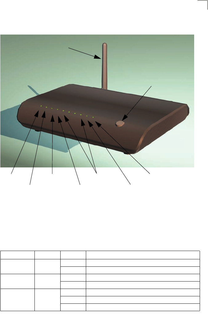
The following figure shows the front components of the Gateway:
Figure 1-2 Top Panel
The Gateway includes key system and port indicators that simplify installation and
network troubleshooting. The LEDs, which are located on the top of the unit for easy
viewing, are described in the following table.
Table 1-2 LED Display Status
LED Color Status Description
PWR Green On The unit is being supplied with power.
Off The unit is not receiving power.
ALARM Orange On Indicates VDSL link failure.
Off Connected to network; VDSL link has been established.
VDSL LINK Green On A stable link has been established with the VDSL network.
Off VDSL link has not been established.
Blinking The unit is synchronizing (initializing the VDSL link).
PWR ALARM VDSL VDSL LAN1 LAN2 LAN3 LAN4 WLAN WPS
LINK TX/RX
WPS
802.11b/g Antenna
WPS Button
Power LED VDSL LINK LED LAN1~4 LEDs WPS LED
ALARM LED VDSL TX/RX LED WLAN LED

Introduction
18
1
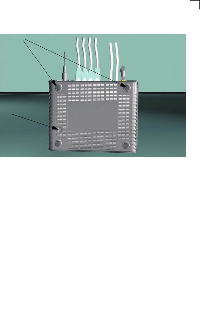
The following figure shows the rear components of the Gateway:
Figure 1-3 Rear Panel
VDSL TX/RX Green On Signal detected on VDSL WAN port.
Off No signal detected on VDSL WAN port.
Blinking Network traffic is crossing the VDSL WAN port.
LAN1-4 Green On Ethernet link signal detected on LAN port.
Off No Ethernet link signal detected on LAN port.
Blinking Network traffic is crossing the LAN port.
WLAN Green
On/
Flashing Indicates the 802.11b/g radio is enabled. Flashing indicates
wireless network activity.
Off Indicates the 802.11b/g radio is disabled.
WPS Green
On (for 10
seconds) Indicates the WPS authentication of a device has been
successfully completed.
Fast
Flashing Indicates the WPS authentication of a client device is in
progress.
Slow
Flashing
(for 10
seconds)*
Indicates the WPS authentication of a device did not complete
after 120 seconds.
Off Indicates that WPS is not in progress.
Table 1-2 LED Display Status (Continued)
LED Color Status Description
Power Receptacle Power Switch RJ-11 Phone Ports
Grounding Point RJ-45 LAN Ports
Description of Hardware
19
1
The following figure shows the base components of the Gateway:
Figure 1-4 Base Panel
Reset Button
Rubber Feet
Introduction
20
1
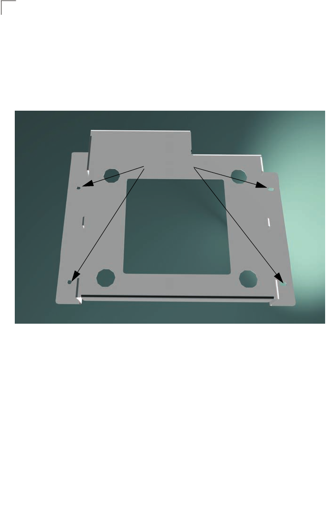
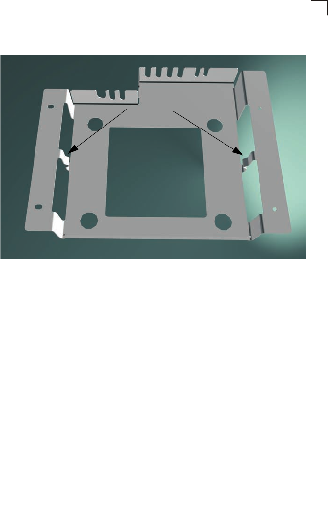
The gateway also includes a wall/ceiling mount bracket illustrated in the picture that
follows. Align the bracket in the direction indicated, marking four screw holes in the
mounting surface with a pencil. Drill four holes in the mounting surface sufficient in size
to accomodate the screws that you are using. If drilling into a wall, make sure to use
wall-plugs as well.
The mounting bracket also includes two clips for attaching the unit to the backet.
Figure 1-5 Mounting Bracket - Front
Before attaching the bracket to the mounting surface be sure to connect the unit to its
required connections, a power source, RJ-11/RJ-45 leads, grounding source, and
power on the unit to make sure that it is functioning and providing connectivity.
Mounting Holes
Description of Hardware
21
1
The mounting bracket also includes two clips for attaching the unit to the backet.
Figure 1-6 Mounting Bracket - Rear
Mounting Clips
Introduction
22
1
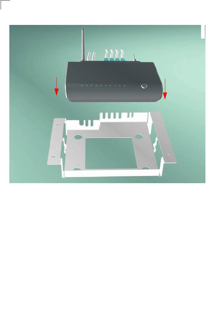
Figure 1-7 Mounting the unit in the bracket
Figure 1-8
Mount the connected unit into the bracket in the direction of the red arrows shown
above, making sure the unit clips correctly into the mounting clips.
Description of Hardware
23
1
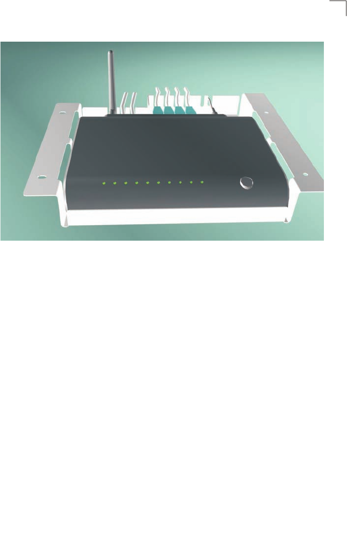
Figure 1-9 Unit in bracket
Introduction
24
1
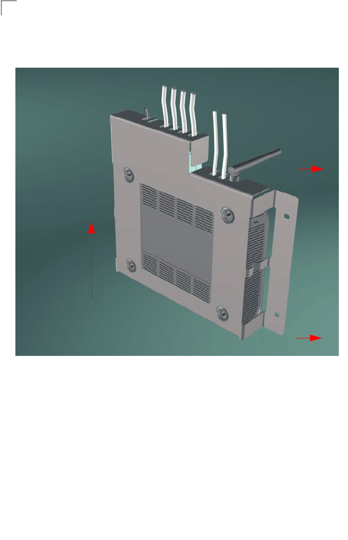
If mounting the assembled unit to a vertical surface follow the directions of the red
arrows indicated below.
Figure 1-10 Attaching the bracket to the mounting surface

25
Chapter 2: Installation
Installation Overview
Before installing the Gateway, verify that you have all the items listed in “Package
Contents.” If any items are missing or damaged, contact your local distributor. Also,
be sure you have all the necessary tools and cabling before installing the Gateway.
Package Contents
After unpacking the Gateway, check the contents of the box to be sure that you have
received the following components:
• 1 Ethernet-over-VDSL2 Gateway
• 1 AC power adapter
• 4 rubber foot pads
• CD-ROM containing this User Guide
• 1 Category 5 UTP straight-through network cable (1 m / 3.28 ft)
• 1 standard RJ-11 telephone cable (1 m / 3.28 ft)
• Mounting bracket (Optional)
• Warranty Card
Please inform your dealer if there are any incorrect, missing, or damaged parts. If
possible, retain the carton, including the original packing materials in case there is a
need to return the Gateway for repair.
System Requirements
Before you start installing the Gateway, make sure you can provide the right operating
environment. See the following installation requirements:
• A PC or Macintosh with a 10/100 Mbps Ethernet adapter card installed.
• For Internet access, the computer must be configured for TCP/IP.
• Power requirements: 12 VDC via the included AC power adapter. Make sure that a
properly grounded power outlet is within 1.8 m (6 ft) of the Gateway.
• The Gateway should be located in a cool dry place, with at least 5 cm (2 in.) of space
on all sides for ventilation.
• Place the Gateway out of direct sunlight, and away from heat sources or areas with
a high amount of electromagnetic interference. The temperature and humidity
should be within the ranges listed in the specifications.
• Be sure that the Gateway is also accessible for Ethernet and telephone cabling.
Installation
26
2
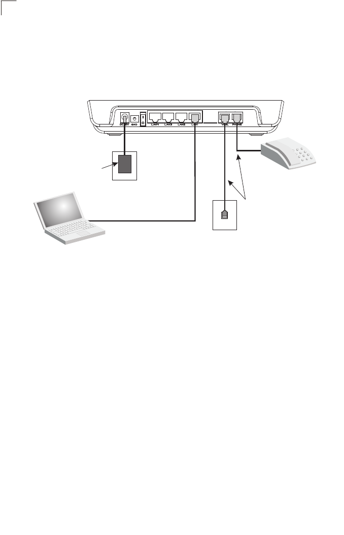
Cable Connections
Depending on the wiring configuration used in your house, separate wall jacks may be
used for telephone and VDSL services. Otherwise, you will need to connect
telephones and your computer directly to the Gateway.
Figure 2-1 Connecting the Gateway
1. Using standard telephone cable, connect the Gateway’s RJ-11 VDSL port to the
RJ-11 telephone wall jack providing the VDSL service.
2. Connect a telephone or fax machine to the RJ-11 port on the Gateway labeled
PHONE.
3. For Ethernet connections, make sure you have installed a 10BASE-T or
100BASE-TX network adapter card in the computers to be connected to the LAN.
4. Prepare straight-through shielded or unshielded twisted-pair cables with RJ-45
plugs at both ends. Use 100-Ohm Category 3, 4, or 5 cable for a 10 Mbps Ethernet
connection, or Category 5 cable for a 100 Mbps connection.
5. Connect one end of the cable to the RJ-45 port of the network interface card, and
the other end to any of the RJ-45 LAN ports on the Gateway.
When inserting an RJ-45 plug, be sure the tab on the plug clicks into position to
ensure that it is properly seated.
Caution: Do not plug a phone jack connector into any RJ-45 port. Use only
twisted-pair cables with RJ-45 connectors that conform to FCC standards.
Notes: 1. When connecting to any network device (such as a PC, hub or switch), you can
use either straight-through or crossover cabling. (Refer to Appendix B: “Cables”
on page 113 for a description of cable types.)
2. Make sure the twisted-pair cable connected to any of the Gateway’s LAN ports
does not exceed 100 meters (328 feet).
Category 5 UTP cable to
Ethernet port on computer
Computer
AC Power Adapter
AC Power Outlet
RJ-11 Ports
RJ-45 Ports
VDSL Line Wall Jack
Standard Telephone Cable
Telephone, Fax, or Modem

Powering On
27
2
Powering On
Plug the power adapter cord into the DC 12V power socket on the Gateway, and then
plug the power adapter directly into a power outlet. Check the LED marked PWR on
the top of the unit to be sure it is on. If the PWR indicator does not light up, refer to
Appendix A: “Troubleshooting” on page 111.
If the Gateway is properly configured, it will take about 30 seconds to establish a
connection with the VDSL service provider after powering up. During this time the
VDSL LINK indicator will flash during synchronization. After the VDSL connection has
been established, the VDSL LINK indicator will stay on.
Configuring the TCP/IP Protocols
To connect the Gateway to a computer through its Ethernet port, the computer must
have an Ethernet network adapter card installed, and be configured for the TCP/IP
protocol. Many service providers configure TCP/IP for client computers automatically
using a networking technology known as Dynamic Host Configuration Protocol
(DHCP). Other service providers may require you to use a specific IP configuration
(known as a static IP address), which must be entered manually.
Carry out the following steps to check that the computer’s Ethernet port is correctly
configured for DHCP.
Windows 95/98/NT
1. Click “Start/Settings/Control Panel.”
2. Click the “Network” icon.
3. For Windows NT, click the “Protocols” tab.
4. Select “TCP/IP” from the list of network protocols; this may include details of
adapters installed in your computer.
5. Click “Properties.”
6. Check the option “Obtain an IP Address.”
Windows 2000
1. Click “Start/Settings/Network/Dial-up Connections.”
2. Click “Local Area Connections.”
3. Select “TCP/IP” from the list of network protocols.
4. Click on “Properties.”
5. Select the option “Obtain an IP Address.”
Windows XP
1. Click “Start/Control Panel/Network Connections.”

Installation
28
2
2. Right-click the “Local Area Connection” icon for the adapter you want to configure.
3. Highlight “Internet Protocol (TCP/IP).”
4. Click on “Properties.”
5. Select the option “Obtain an IP address automatically” and “Obtain DNS server
address automatically.”
Windows Vista
1. Click Start/Control Panel.
2. Double-click “Network and Sharing Center.”
3. Click “View status.”
4. Click “Properties.” If the “User Account Control” window appears, click “Continue.”
5. Highlight “Internet Protocol Version 6 (TCP/IPv6)” or “Internet Protocol Version 4
(TCP/IPv4),” and click “Properties.”
6. Select the option “Obtain an IP address automatically” and “Obtain DNS server
address automatically.”
Mac OS
1. Pull down the Apple Menu. Click “Control Panels” and select “TCP/IP.”
2. In the TCP/IP dialog box, verify that “Ethernet” is selected in the “Connect Via:”
field.
3. If “Using DHCP Server” is already selected in the “Configure” field, your computer
is already configured for DHCP. Otherwise, select “Using DHCP Server” in the
“Configure” field and close the window.
4. Another box will appear asking whether you want to save your TCP/IP settings.
Click “Save.”
5. Your service provider will now be able to automatically assign an IP address to your
computer.

29
Chapter 3: Network Planning
Application Examples
VDSL provides significant savings on network installation, equipment, and service
fees. Internet services operate over existing phone cabling and a minimal amount of
network equipment. The only changes require installing a VDSL CPE (or Gateway
as described in this manual) for each client, and a VDSL switch in the basement or
wiring closet. Internet service can then be provided over a direct Ethernet connectio
n
from your ISP. For non-commercial environments, you can run the switch through a
broadband router (such as this Gateway) at the customer’s site. This will allow you
to use a single-user account and ISP sharing to significantly reduce network access
charges.
Using VDSL provides Internet connections of up to 100 Mbps downstream and 100
Mbps upstream at 200 meters. Installation is extremely economical for
multiple-tenant dwellings such as apartment buildings, hotels or school dormitories,
as well as commercial buildings.
VDSL provides multiple-user access to the Internet with benefits including:
• Internet services such as e-mail over faster connections than currently possible
with other options such as cable modem or ADSL
• Multimedia applications such as video and virtual gaming made available to the
broader public for the first time
• Access to corporate intranets at speeds close to that available in the office
• Both local network applications and Internet services are supported for commercial
environments
Networking Concepts
Route Determination
Depending on the transport protocol used, this device can handle traffic as a Layer-2
bridge, using only the physical address stored in the packet’s source and destination
address fields. Or it can forward traffic as a fully functional Layer-3 router, using a
specific route (that is, next hop) for each IP host or subnet that is statically
configured or learned through dynamic routing protocols.
Bridging
When Bridge Mode is selected, the Gateway behaves like a wire directly connecting
your local network to the ISP. The Gateway simply stores the physical address and
corresponding port number of each incoming packet in an address table. This
information is subsequently used to filter packets whose destination address is on

30
Network Planning
3
the same segment (that is, the local network or remote network) as the source
address.
Routing
When Router Mode is selected, the Gateway forwards incoming IP packets and
uses RIP or RIP-2 for routing path management if enabled. The router supports both
static routing and dynamic routing.
• Static routing requires routing information to be stored in the router, either manually
or when a connection is set up, using the default gateway designated by your ISP.
• Dynamic routing uses a routing protocol to exchange routing information,
calculates routing tables, and responds to changes in the status or traffic on the
network.
Dynamic Routing Protocols - This router supports both RIP and RIP-2 dynamic
routing protocols. Routing Information Protocol (RIP) is the most widely used
method for dynamically maintaining routing tables in small to medium networks. RIP
uses a distance vector-based approach to routing. Routes are chosen to minimize
the distance vector, or hop count, which serves as a rough estimate of transmission
cost. Each router broadcasts an advertisement every 30 seconds, together with any
updates to its routing table. This allows all routers on the network to build consistent
tables of next hop links which lead to relevant subnets.
RIP-2 is a compatible upgrade to RIP. However, RIP-2 adds useful capabilities for
plain text authentication, multiple independent RIP domains, variable length subnet
masks, and multicast transmissions for route advertising (see RFC 1388).
Note: If the destination route is not found in the routing table, the router simply transmits
the packet to a default router for resolution.
Network Applications
The Gateway can be configured as a bridge for making a transparent connection to
a remote site, or as a router for accessing the Internet. These applications are briefly
described in the following sections.
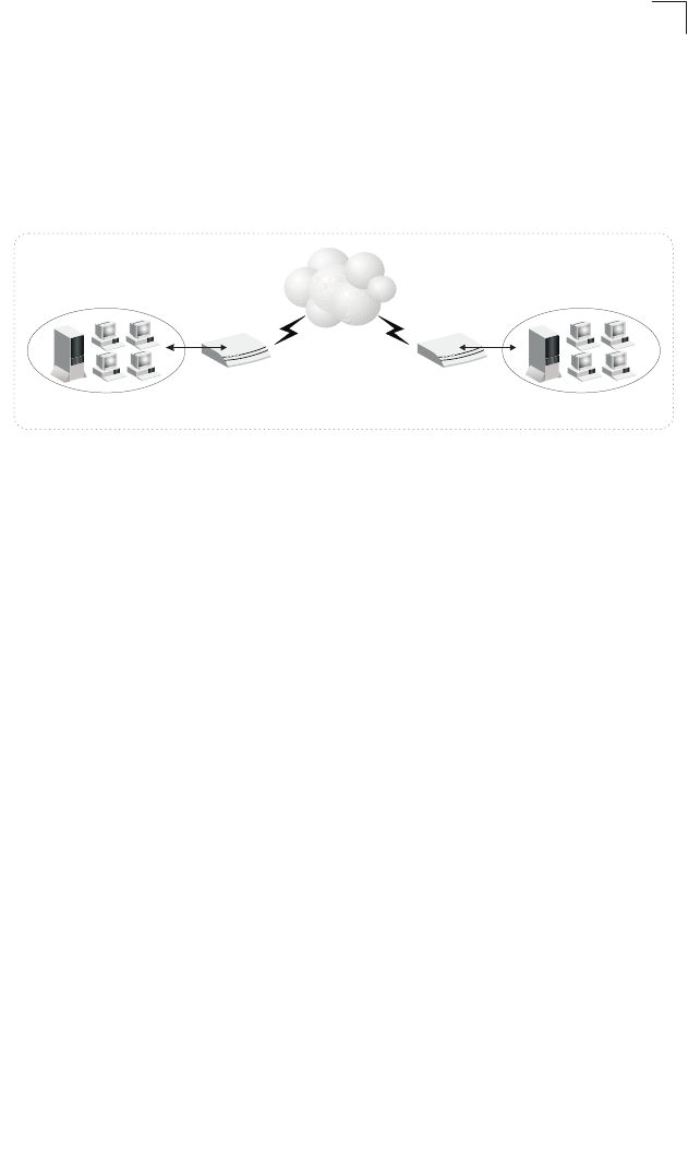
Accessing a Remote Site
The Gateway can be configured to act as a transparent bridge between a local PC
or LAN attached to the Ethernet ports and a remote site across the WAN VDSL link.
Bridging can be used to make two separate networks appear as if they were part of
the same physical network. When data enters an Ethernet port on the Gateway, its
destination MAC address (physical address) is checked in the address database to
see if it is located in the local segment (that is, attached to one of the Gateway’s
Ethernet ports). If the destination address is not found, the frame is forwarded to the
VDSL port and queued for output. If the destination address is found to belong to
one of the local ports, the frame is dropped or “filtered.” However, note that
broadcast or multicast frames are always broadcast across the VDSL link.
31
Network Applications
3
The source MAC address of each frame is recorded into the address database only
if it belongs to the local LAN segment. This information is then used to make
subsequent decisions on frame forwarding. The address database can hold up to
512 unique MAC addresses. An entry in the address database will be discarded only
if it has not been accessed for a period of time called the aging time. This is to
ensure that correct forwarding decisions can still be made when a node is moved to
another port, and to keep the table clean.
Figure 3-1 Transparent Bridged Network
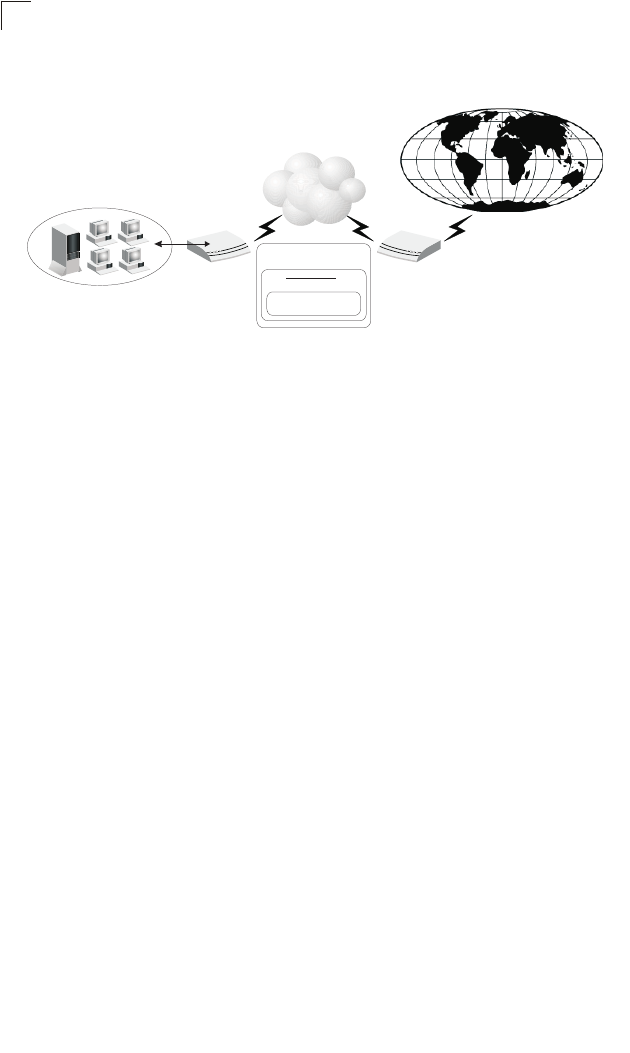
Accessing the Internet
To access the Internet, which uses the TCP/IP protocol exclusively, the Gateway
should be configured to function as a router. One side of the connection is formed by
the ports attached to a local 10/100Mbps Ethernet LAN (or directly to a host PC with
an Ethernet adapter), while the other is the Layer 3 transport service running on the
VDSL port. When the Gateway receives an IP packet over the WAN interface, the
destination address is checked in the routing table. If the address is found, the
packet is forwarded to the associated interface/port. Otherwise, the packet is
dropped. When it receives an IP packet over the LAN interface, it also checks the
routing table. If the source and destination address are in the same subnet, no
action is required because the packet can be passed on at Layer 2. If the address is
found to be in a remote subnet, the packet is forwarded to the next hop router.
Otherwise, if not found in the address table, it is sent to the default gateway
designated by the ISP.
The routing table contains information on which networks are accessible through
each interface. It can be dynamically updated using the Routing Information Protocol
(RIP), or statically configured through the web management interface. If you use
RIP, the router will exchange information with neighboring routers to learn the best
routes to remote networks, and advertise the networks for which it can provide the
best route.
When the system is powered on, the Gateway builds its own routing
database
according to previous static routing entries, and/or collects
routing information from
adjacent routers through RIP or RIP-2
protocol. RIP (that is, RIP-1) is generally
supported by all routers, but RIP-2 carries
more information which allows the router to
10/100Mbps Ethernet LAN
ECG9210-04
ECG9210-04
VDSL
10/100Mbps Ethernet LAN
32
Network Planning
3
make better choices on the most appropriate path to a remote network. However,
RIP-1 is adequate for most networks and involves less overhead.
Figure 3-2 Routed Network
Network Services
DHCP Service
Dynamic Host Configuration Protocol (DHCP) allows network clients to dynamically
obtain TCP/IP configuration information upon bootup. When a DHCP client starts, it
broadcasts a DHCP request. The Gateway can be set up to respond to the client
with configuration information (including, an IP address, subnet mask and default IP
gateway) or to relay the request to another DHCP server.
The Gateway can be configured with an client pool of up to 254 IP addresses. These
addresses are leased to the requesting client for a specified amount of time, or until
the device surrenders the address during shut-down. Windows 95, 98, NT, 2000,
and Vista hosts as well as other systems that provide DHCP client services can be
configured with a TCP/IP address provided by this Gateway.
DNS Service
The DNS protocol is used to map host names to IP addresses. The Gateway can
specify a well-known DNS server, or relay service requests directly through to the
ISP for resolution.
NAT Functions
Network Address Translation (NAT) allows you to map multiple IP addresses for
clients from your local Ethernet through to the Internet using a single IP address for
the VDSL port. This allows multiple users to access the Internet using a single-user
account from your ISP.
LocalArea Network
ECG9210-04
VDSL
VDSL
TCP/IP Protocol
PPP/ATM
Internet
ISP
DSLAM

33
Network Services
3
Virtual Server
You can also map multiple local servers to the Gateway’s external IP address. In this
way, service requests from Internet users can be redirected to designated servers
on the local network. This allows you to define a single access point for all the
Internet services provided at your site, such as a local web server or an FTP server.
And then, just by entering the external IP address for your site (provided by your
ISP), Internet users can access the service they need at the local address to which
you redirect them.
NAT allows Internet users through to the services you designate, but because all
your internal IP addresses are private, this provides a natural firewall that prevents
direct access to local resources by hackers. NAT also simplifies address
management because changes to IP addresses for local services will not affect
access for Internet users accessing your site. For example, when you update an IP
address for an Internet server on your local network, Internet users can continue to
access the service via the same external IP address.
User-Definable Application Sensing Tunnel
You can define special applications that require multiple connections such as
Internet gaming, videoconferencing, and Internet telephony. The Gateway can then
sense the application type and open a multi-port TCP/UDP tunnel for it.
DMZ Host Support
DMZ allows a networked computer to be fully exposed to the Internet. This function
is used when the special application sensing tunnel is insufficient to allow an
application to function correctly.
Security
The Gateway supports security features that can deny Internet access to specified
users, or filter all requests for specific services the administrator does not want to
serve. The Gateway’s firewall can also block common hacker attacks, including IP
Spoofing, Land Attack, Ping of Death, IP with zero length, Smurf Attack, UDP port
loopback, Snork Attack, TCP null scan, and TCP SYN flooding.
It also supports the following additional security features:
• Disable Ping from the LAN or WAN side
• Discard port scans from the WAN side
• Filter specific MAC or IP addresses
• Block certain web sites based a specified URL
• Stateful Packet Inspection which accepts only legitimate packets based on
connection type

34
Network Planning
3
Virtual Private Network
The Gateway supports three of the most commonly used VPN protocols – PPTP,
L2TP and IPSec. These protocols allow remote users to establish a secure
connection to their corporate network. If your service provider supports VPNs, then
any of these protocols can be used to create an authenticated and encrypted tunnel
for passing secure data over the Internet (i.e., a traditionally shared data network).
The VPN protocols supported by the Gateway are briefly described below.
Point-to-Point Tunneling Protocol – Provides a secure tunnel for remote client
access to a PPTP security gateway. PPTP includes provisions for call origination
and flow control required by ISPs.
Layer Two Tunneling Protocol – L2TP includes most of the features provided by
PPTP, but has less overhead and is more suited for managed networks.
IP Security – Provides IP network-layer encryption. IPSec can support large
encryption networks (such as the Internet) by using digital certificates for device
authentication.
35
Chapter 4: Initial Configuration
Accessing the Setup Wizard
The Gateway provides a Setup Wizard for initial configuration of the unit’s operating
mode (Bridge or Router as described in “Networking Concepts” on page 29) and
WAN IP address (when Router mode is selected).
For initial configuration, connect a PC directly to one of the LAN ports on the back of
the unit, and use a web browser (such as Internet Explorer 6.0 or above, or Mozilla
Firefox 2.0.0.0 or above) to connect to the Gateway.
The Gateway has a default IP address of 192.168.2.1 and a subnet mask of
255.255.255.0. If your PC is set to “Obtain an IP address automatically” (that is, set
as a DHCP client), you can connect immediately to the web interface. Otherwise,
you must set your PC IP address to be on the same subnet as the Gateway (that is,
the PC and Gateway addresses must both start with 192.168.2.x).
To access the Setup Wizard, follow these steps:
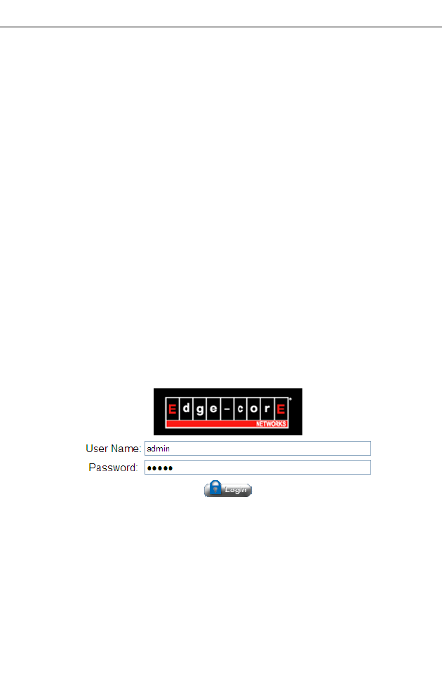
1. Use your web browser to connect to the management interface using the default
IP address of 192.168.2.1.
2. Log into the Gateway’s management interface by entering the default user name
and password both as “admin,” and then click OK.
Figure 4-1 Login Dialog Box
Initial Configuration
36
4
3. Click WIZARD when the home page appears.
Figure 4-2 Home Page
Using the Setup Wizard
There are only a few basic steps you need to set up the Gateway, and to configure
an IP address for the WAN interface (when operating in Router mode).
The Setup Wizard takes you through the configuration procedures shown below:
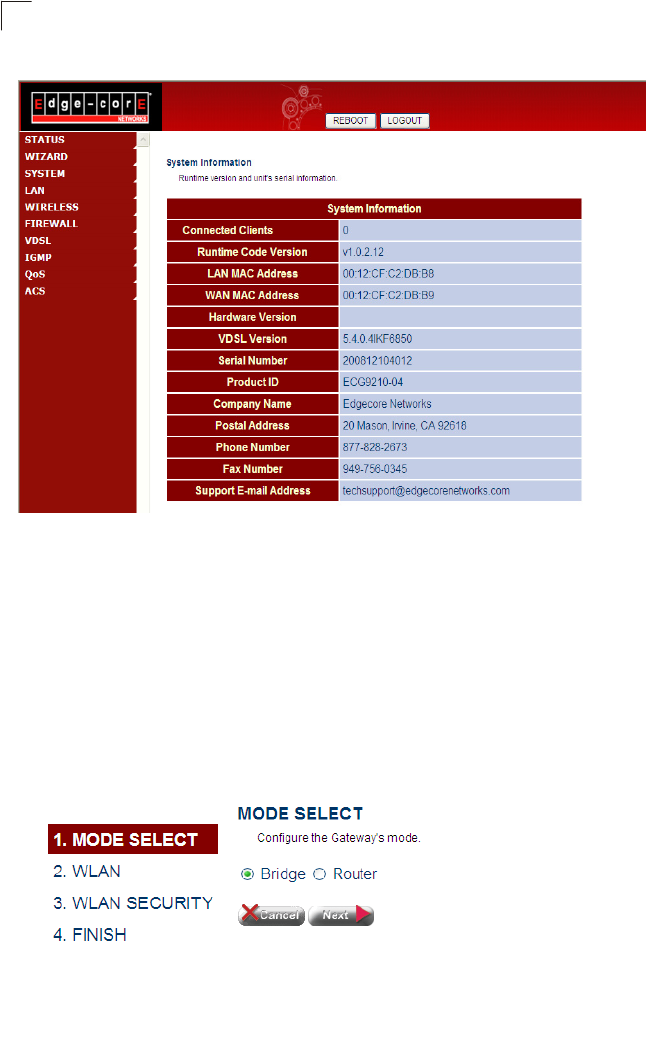
1. Select the Operating Mode – By default, the Gateway is set to operate in Bridge
mode, and requires no other features to be set before using the Advanced Setup
menu. If you plan on using the Gateway in Bridge mode, just click Next and skip
to Step 4. Otherwise, select Router mode, and click Next.
Figure 4-3 Mode Selection (Bridge Mode)
Using the Setup Wizard
37
4
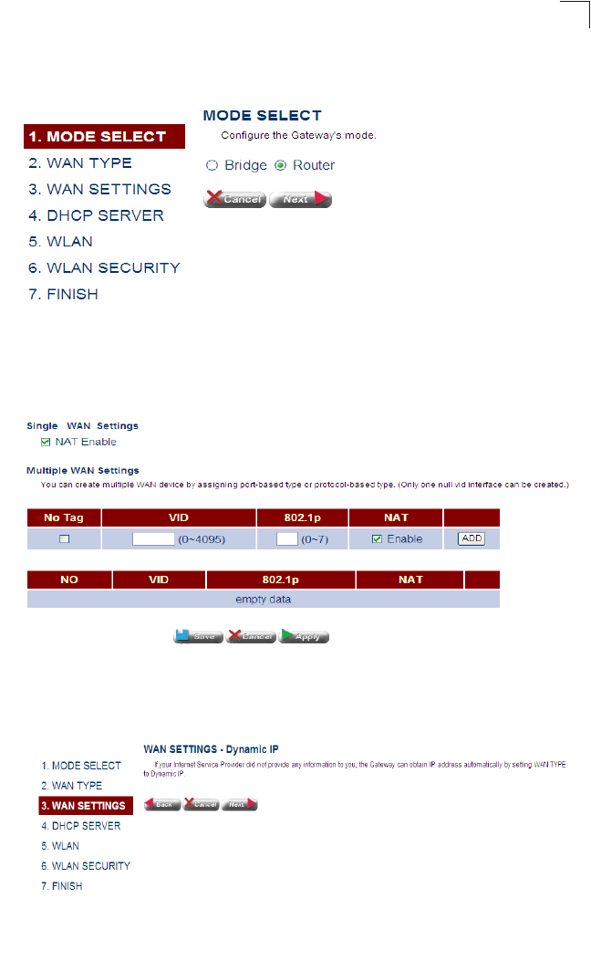
If Router mode is selected the information displayed on the screen changes to
that shown below.
Figure 4-4 Mode Selection (Router Mode)
2. Set the WAN Connection Type – By default, the Gateway’s WAN port is
configured for dynamic IP assignment using DHCP. Select the option indicated by
your Internet service provider, and click Next.
Figure 4-5 WAN Type
•Dynamic IP – If you selected Dynamic IP, the following screen will appear.
Click Next to confirm your selection.
Figure 4-6 WAN Setting (Dynamic IP)
Initial Configuration
38
4
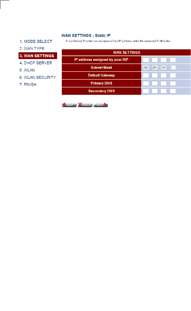
•Static IP – If you selected Static-IP, the following screen will appear. Fill in the
required settings, and then click Next.
Figure 4-7 WAN Setting (Static IP)
Field Attributes
•IP address assigned by your ISP – IP address of the WAN interface. Valid
addresses consist of four decimal numbers, 0 to 255, separated by periods.
•Subnet Mask – This mask identifies the subnet and host portion of the IP
address.
•Default Address – The IP address of the gateway router which is used if the
requested destination address is not on the local subnet, nor in any of the
routing tables.
•Primary DNS – The IP address of the Primary Domain Name Server on the
network. A DNS maps numerical IP addresses to domain names which can
be used to identify network hosts by familiar names instead of the IP
addresses.
•Secondary DNS – The secondary domain name server.
Using the Setup Wizard
39
4
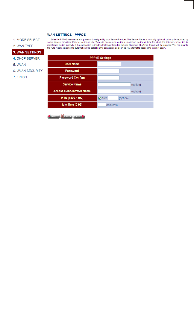
•PPPoE – If you selected PPPoE, the following screen will appear. Fill in the
required settings, and then click Next.
Figure 4-8 WAN Setting (PPPoE)
Field Attributes
•User Name – Sets the PPPoE user name. (Range: 1-32 characters)
•Password – Sets a PPPoE password. (Range: 1-32 characters)
•Password Confirm – Prompts you to re-enter your password.
•Service Name – The service name assigned for the PPPoE connection. The
service name is normally optional, but may be required by some service
providers. (Range: 1-32 characters)
•Access Concentrator Name – The name of the access concentrator to use
in PPPoE Active Discovery Offers (PADO). (Range: 1-32 characters)
•MTU (1400-1492) – Sets the maximum packet size that the WAN port may
transmit. The Maximum Transmission Unit is expressed in bytes. By default,
the Gateway will send several test messages to determine the MTU for the
upstream connection. (Range: 1400-1492 bytes)
•Idle Time (0-99) – The maximum length of inactive time the unit will stay
connected to the service provider before disconnecting. Select
“Auto-reconnect” to reconnect to the upstream gateway whenever an
Internet access request is made. (Range: 1-99 minutes; Default: 2 minutes)
Initial Configuration
40
4
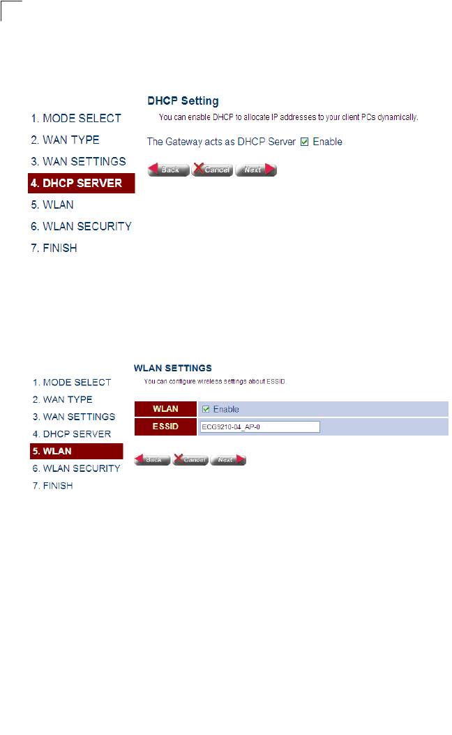
3. Enable Local DHCP Service – By default, the Gateway’s is configured to
provide DHCP service to any client attached to the Gateway’s LAN ports. Set the
administrative status of this feature, and click Next.
Figure 4-9 DHCP Setting
4. Set Wireless Settings – The wireless radio on the Gateway is disabled by
default. To enable it check the WLAN Enable box. The access point’s ESSID is
automatically set, but may be changed by altering this field. Click Next to continue
with the wireless setup.
Figure 4-10 WLAN Setting
Field Attributes
•WLAN – Enables the wireless radio interface.
•ESSID – The name of the wireless network service provided by the VAP.
Clients that want to connect to the network must set their SSID to the same
as that of the VAP interface. (Default: ECG9210-04_AP-0; Range: 1-32
characters)
Using the Setup Wizard
41
4
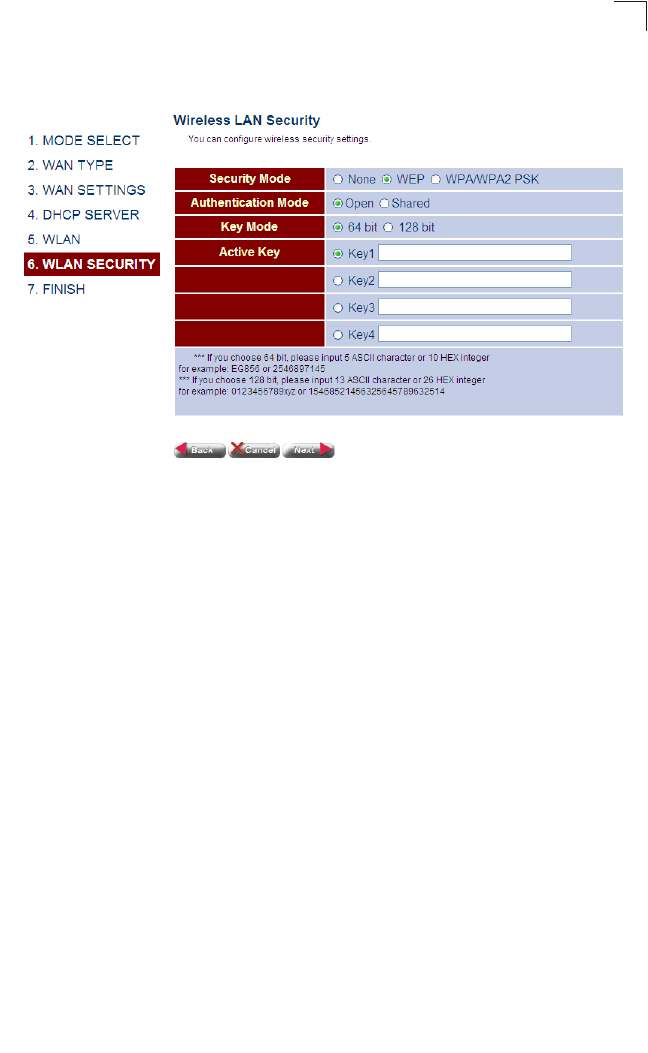
5. Setting WLAN Security (WEP) – Sets the wireless security encryption key for
the wireless network.
Figure 4-11 WLAN Security - WEP
Field Attributes
•None – Disables security on the access point. (Default: Disabled)
• WEP – WEP is used as the multicast encryption cipher.
• Authentication Mode – Defines the mode with which the access point will
associate with other clients.
• Key Mode – Select 64 Bit, or 128 Bit length. Note that the same size of
encryption key must be supported on all wireless clients.
(Default: 64 Bit)
• Active Key – Selects the key number to use for encryption for the VAP
interface. If the clients have all four keys configured to the same values, you
can change the encryption key to any of the eight settings without having to
update the client keys. (Default: Key 1)

Initial Configuration
42
4
Setting WLAN Security (WPA) – Sets the WPA/WPA2 PSK wireless security
encryption key for the wireless network.
Figure 4-12 WLAN Security - WPA
Field Attributes
•TKIP/AFS – TKIP/AES is used as the multicast encryption cipher.
•AES – AES is used as the multicast encryption cipher. AES-CCMP is the
standard encryption cipher required for WPA2.
6. Click Next followed by Apply on the next srceen to save your settings. The unit
will save your settings and restart. Note that your configuration changes are not
saved until the Setup Wizard is completed and the system restarted.
Figure 4-13 Saving Your Settings

Using the Setup Wizard
43
4
7. When the system restarts, a countdown window displays for about 60 seconds.
Figure 4-14 Reboot

Initial Configuration
44
4

45
Chapter 5:
System Configuration
Using the Web Interface
The Gateway provides a web-based management interface for configuring device
features and viewing statistics to monitor network activity. This interface can be
accessed by any computer on the network using a standard web browser (such as
Internet Explorer 6.0 or above, or Mozilla Firefox 2.0.0.0 or above).
Note: You can also use the Command Line Interface (CLI) to manage the Gateway over
a serial connection to the console port or via Telnet or SSH.
To make an initial connection to the management interface, connect a PC to one of
the Gateway’s LAN ports. Then either set it to “Obtain an IP address automatically”
(DHCP service is enabled by default on the Gateway) or configure it with a static
address within the same subnet as that used by the Gateway (that is, 192.168.2.x
with the subnet mask 255.255.255.0).
To access the configuration menu, follow these steps:
1. Use your web browser to connect to the management interface using the
default IP address of 192.168.2.1.
2. Log into the Gateway’s management interface by entering “admin” as both the
default user name and password.
Note: It is strongly recommended to change the default password the first time you
access the web interface. For information on changing the password, see “Admin
Settings” on page 57.
System Configuration
46
5
Home Page
When your web browser connects with the Gateway’s web agent, the home page is
displayed as shown below. For initial configuration, you can use the Setup Wizard as
described in the preceding chapter. To carry out more detailed configuration tasks,
use the Advanced Setup Menu, as described in this chapter.
Figure 5-1 Home Page
Using the Web Interface
47
5
Click “START WITH ADVANCED SETUP” to open the Advanced Settings menu as
shown below. By default, the Gateway is set to Bridge Mode. (For a brief description
of Bridge Mode and Router Mode, see “Route Determination” on page 29.)
Figure 5-2 Initial Page for Advanced Settings (Router Mode)
Advanced Settings Menu
The Advanced Settings pages display the main menu on the left side of the screen
and sub-menu tabs at the top of screen. The main menu links are used to navigate
between key functional categories, while the sub-menus list related topics within
each of these categories. The sub-menus display configuration parameters, fixed
system information, or network statistics.
The information in this chapter is organized to reflect the structure of the web
management screens for easy reference.
The configuration pages include the options listed in the table below. For details on
configuring each feature, refer to the corresponding page number.
Note: The displayed pages and settings may differ depending on whether the unit is in
Bridge Mode or Router Mode.
Table 5-1 Advanced Settings Menu
Menu Description Mode Page
STATUS System information, access logs, and DHCP client list Both 50
Information Shows firmware/hardware and VDSL code versions, as
well as the unit’s serial number Both 50

System Configuration
48
5
WAN Shows configuration status (DHCP or static), IP
address, subnet mask, DNS servers, gateway address,
and WAN link status
Router 51
LAN Shows IP address, subnet mask, and local DHCP
server status Router 52
Log Displays a log of all network access and service activity Both 53
DHCP Displays addresses currently bound to DHCP clients Router 54
SYSTEM Basic administrative settings Both 54
Mode Sets the device to operate as s bridge or router Both 54
Time Configures NTP settings, including time zone, server,
and refresh time Router 57
Admin Configures access password, and IP address(es)
authorized for remote access over the WAN link Both 57
Tools Includes management tools for pinging another device,
updating firmware, restoring factory defaults, and
rebooting the unit
Both 58
UPnP Enables UPnP auto-discovery mechanism Router 59
Services Enables TFTP, Telnet, and Secure Shell access Router 60
SNMP Configures SNMP settings. Both 61
DNS Dynamic Name Server Both 69
WAN Wide Area Network Router 69
WAN Type Configures virtual WAN ports Both 64
WAN Settings Configures address configuration options for DHCP,
static assignment or PPPoE Router 64
DDNS Configures dynamic DNS services for DynDNS and
TZO servers Router 69
LAN Local Area Network Both 69
LAN Type Configures VLANs Both 69
LAN Settings Configures IP settings for the LAN, including IP
address, DHCP server, and DNS assignment Both 69
Switch Ports Configures port connection parameters, including
speed and duplex mode Both 72
ROUTE Route Configuration Router 69
Static Routing Configures and displays static routing entries Router 73
Dynamic Routing Configures dynamic route learning from LAN and WAN
interfaces Router 74
Policy Routing Configures IP policy routing Router 76
Wireless Wireless Configuration Both 77
Table 5-1 Advanced Settings Menu (Continued)
Menu Description Mode Page

Using the Web Interface
49
5
Wireless Configures wireless AP settings Both 79
Client List List of all wireless clients currently associated with the
AP Both 85
NAT Network Address Translation Router 86
Virtual Server Maps public to private service addresses Router 86
Port Mapping Maps one or more service ports to a local server Router 87
DMZ Allows a specified host on the local network to access
the Internet without any firewall protection Router 89
FIREWALL Firewall Configuration Both 90
Firewall Settings Enables or disables the firewall, and sets default policy
for addresses not found in the MAC or IP filtering list Both 90
IP Filtering Filters IP addresses of clients accessing the Internet Both 91
ALG Enables or disables customized NAT traversal filters for
SIP, H323, IRC, PPTP, SNMP, TFTP, and IPSEC. Router 92
Remote Control Configures remote management access of the WAN
port. Both 93
VDSL VDSL Configuration Both 95
Rate Information Displays general VDSL status information for the VDSL
line, BME and specific ports; also displays current rate
for various stream types
Both 95
Performance Counters Displays performance information including common
error conditions for the VDSL line Both 98
SNR Displays counters for sound-to-noise ratio
measurements Both 99
IGMP Internet Group Management Protocol Both 101
IGMP Configures IGMP Proxy, IGMP Snooping, Fast Leave Both 102
QoS Quality of Service Both 104
QoS Settings Enables or disables QoS, sets the upstream rate limit,
and the queuing mode Both 104
Traffic Classification Configures diffServ priorities based on protocol type,
source and destination addresses, and TCP/UDP port Router 105
ACS Auto-configuration server (TR-069 and TR-098) Router 108
TR Settings Configures parameters for establishing connection
between Gateway and auto-configuration server Router 108
Table 5-1 Advanced Settings Menu (Continued)
Menu Description Mode Page
System Configuration
50
5
Status Information
The Status pages display details on the current configuration and status of the
Gateway, network access logs, and DHCP client lists.
Note: The Status Information pages display different statistics depending on the mode
selected – Bridge or Router. Refer to “Networking Concepts” on page 3-29 for a
general description about these operating modes. Refer to “System Mode” on
page 5-54 for information on setting the operation mode.
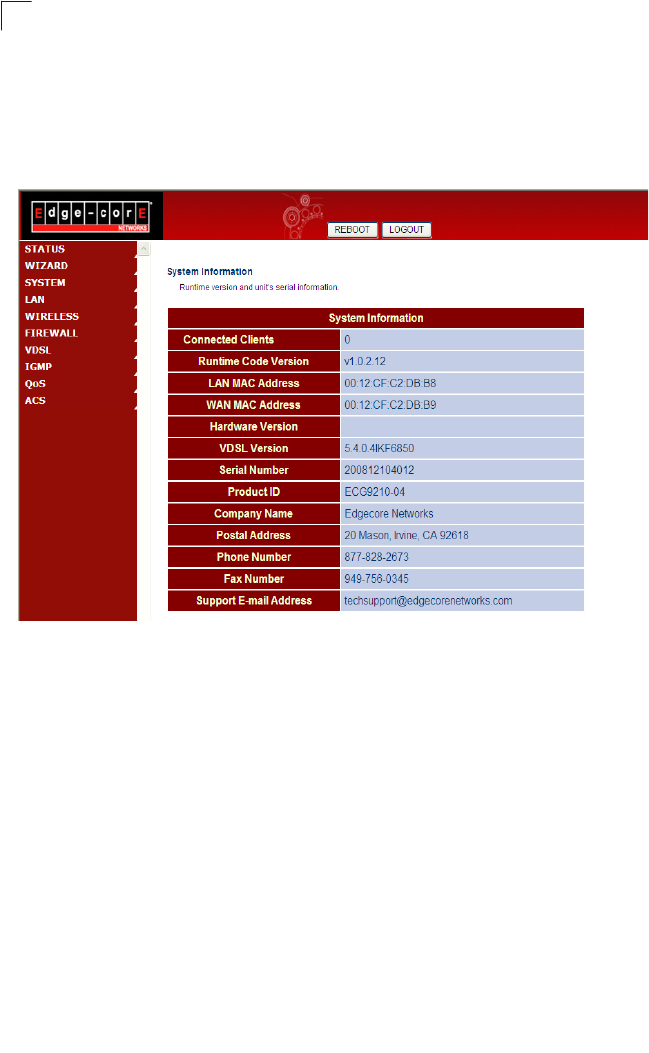
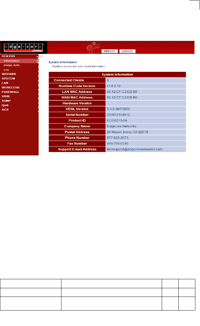
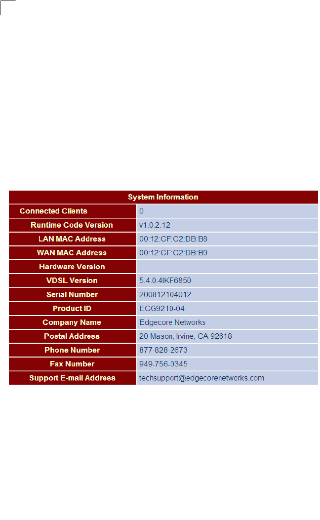
System Information
The System Information page displays firmware/hardware and VDSL code versions,
the physical address of the LAN and WAN interfaces, and the unit’s serial number.
Click Status, System Info.
Figure 5-3 System Information
Field Attributes
•Connected Clients – The number of DHCP clients serviced by the Gateway.
•Runtime Code Version – Version number of operation code.
•LAN MAC Address – The physical layer address for the LAN interface.
•WAN MAC Address – The physical layer address for the WAN interface.
•Hardware Version – Hardware version of the main board.
•VDSL Version – VDSL firmware version.
•Serial Number – Serial number of the main board.
•Product ID – The product identification number.
Status Information
51
5
•Company Name – The name of the manufacturer.
•Postal Address – The postal address of the manufacturer.
•Phone Number – The phone number of the manufacturer.
• Fax Number(option) – The facsimile number of the manufacturer.
• Support E-mail Address – The support email address.
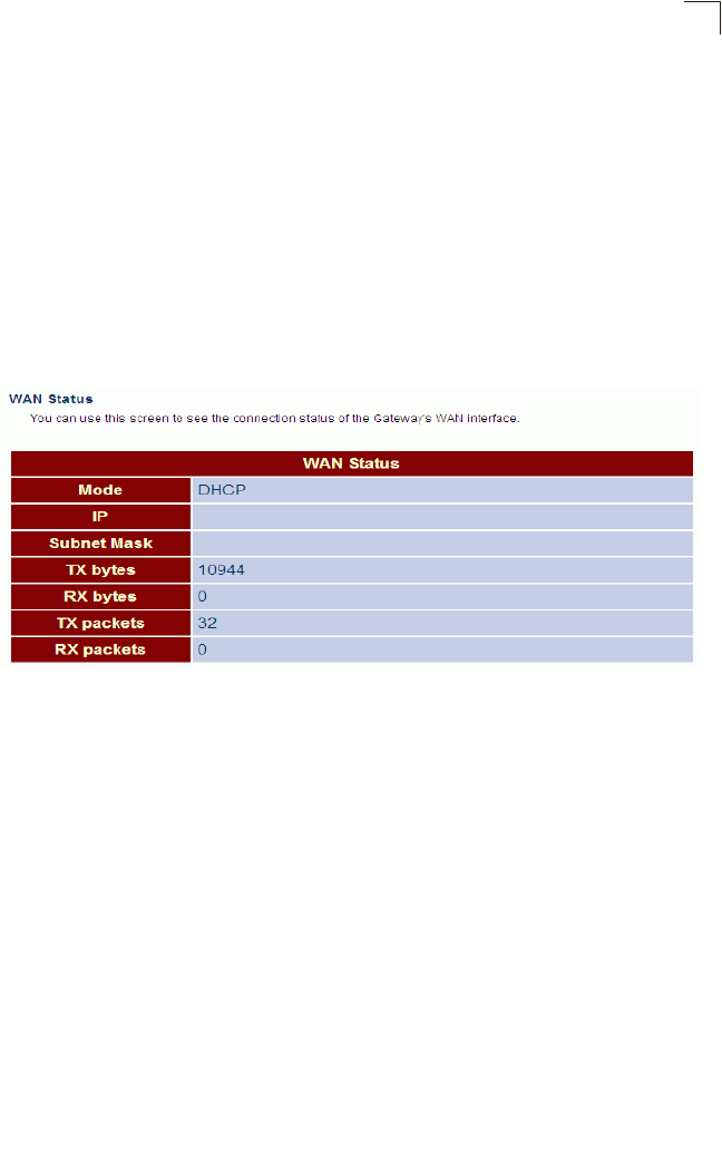
WAN Status
This page shows the administrative status, the IP address configuration mode
(DHCP, static assignment, or PPPoE), the IP address, subnet mask, DNS servers,
gateway address, and WAN link status.
Click Status, WAN Status.
Figure 5-4 WAN Status
Field Attributes
•Mode – The administrative status of the WAN interface (on or off), the IP address
configuration mode (DHCP, Static IP, or Pope).
•TX packets – The total number of transmitted packets sent by the unit since boot
up.
•TX bytes – The total number of transmitted bytes sent by the unit since boot up.
•RX packets – The total number of packets received by the unit since connection
to a network.
•RX bytes – The total number of bytes received by the unit since connection to a
network.
System Configuration
52
5
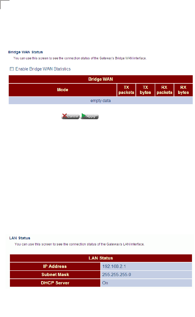
Bridge WAN Status
This page shows the administrative status of the bridge WAN port.
Click Status, Bridge WAN Status.
Figure 5-5 Bridge WAN Status
Field Attributes
•Mode – The administrative status of the bridge WAN port.
•TX packets – The total number of transmitted packets sent by the unit since boot
up.
•TX bytes – The total number of transmitted bytes sent by the unit since boot up.
•RX packets – The total number of packets received by the unit since connection
to a network.
•RX bytes – The total number of bytes received by the unit since connection to a
network.
LAN Status
This page shows the IP address, subnet mask, and local DHCP server status.
Click Status, LAN Status.
Figure 5-6 LAN Status
Field Attributes
•IP Address – IP address of the LAN interface.
Status Information
53
5
•Subnet Mask – This mask identifies the subnet and host portion of the IP address.
•DHCP Server – Shows if the Gateway’s DHCP server is enabled or disabled.
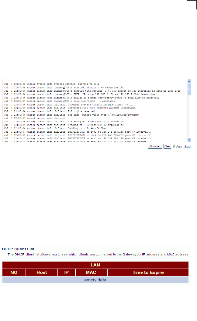
System Log
This page displays a log of all network access requests by client devices and service
responses sent from the Gateway.
Click Status, System Log.
Figure 5-7 System Log
Field Attributes
•Log Entry – Shows the date, time, process, and description.
•Download – Downloads the log table as an raw text file. In Windows, this is
downloaded to Notepad.
•Clear – Flushes the log table.
•Auto Refresh – Automatically updates the log table every 5 seconds.
DHCP Client List
This page displays the addresses currently bound to DHCP clients.
Click Status, DHCP Client List.
Figure 5-8 DHCP Client List
Field Attributes
•LAN Client List – The list of assigned addresses for the listed LAN.
System Configuration
54
5
•Count Down – The time after which the connection will expire and the DHCP client
must request a new IP address.
•MAC Address – The MAC address of the DHCP client.
•IP Address – The IP address assigned to the DHCP client.
•Host – The host name of the DHCP client.
System Configuration
The System pages are used to configure basic administrative settings, including the
operating mode (bridge or router), NTP server selection, management access
control through a password or specified host address, firmware upgrade, UPnP
auto-discovery, and management through TFTP, Telnet or Secure Shell.
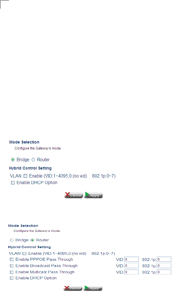
System Mode
This page sets the Gateway to operate as s bridge or router. Refer to “Networking
Concepts” on page 3-29 for a general description about these operating modes.
Click System, System Mode. Select the required operating mode, and click Apply.
Figure 5-9 System Mode - Bridge
Figure 5-10 System Mode - Router
System Configuration
55
5
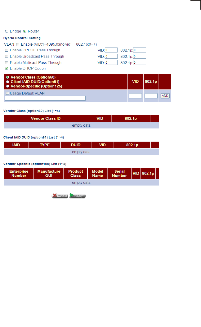
Figure 5-11 System Mode - Router - DHCP Enabled
Field Attributes
•Bridge – Sets the Gateway to function as a Layer-2 bridge, using only the physical
address stored in the packet’s source and destination address fields to pass traffic.
•Router – Sets the Gateway to function as a Layer-3 router, using a specific route
(that is, next hop) for each IP host or subnet that is statically configured or learned
through dynamic routing protocols.
The Gateway must reboot after each mode change. It takes about 60 seconds for
the router to reboot and start forwarding traffic on the LAN and WAN interfaces.
Also note that the menus provided by the Gateway differ for the bridge and router
operating modes as noted in Table 5-1, “Advanced Settings Menu,” on page 47.
•VLAN Enable – Enables VLANs. (Router mode only)
•Enable PPPOE Pass Through – Enables PPPoE Pass Through
System Configuration
56
5
•Enable Broadcast Pass Through – Enables Broadcast Pass Through.
•VID – Specifies the VLAN ID.
•802.1p – Specifies quality of service level.
•Enable DHCP Option –
•Option 60 – Option 60 allows a DHCP server to differentiate between the two kinds
of client machines and process the requests from the two types of modems
appropriately. The DHCP server and client send a vendor class option that
contains an ASCII-encoded string with three parts delimited by a / character. The
first part is AAPLBSDPC, which advertises BSDP capability. The second part is the
client's architecture ("ppc" or "i386"). The third part is a system identifier.
•Option 61 – Specifies the client MAC address.
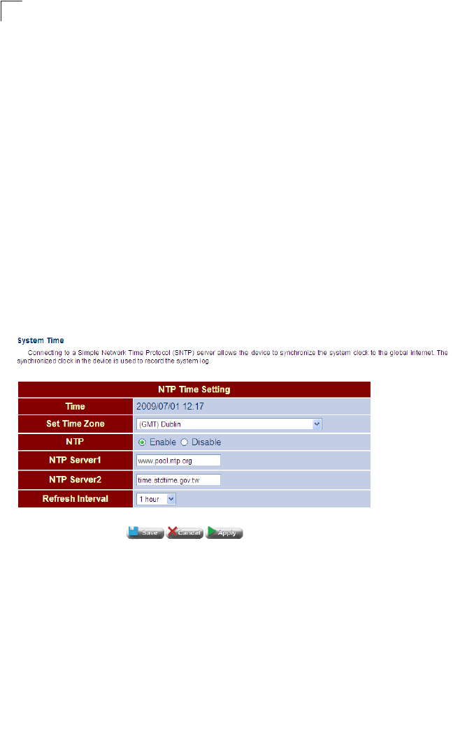
System Time
This page configures the local time zone, and Network Time Protocol (NTP) settings,
including the NTP server to use and the refresh time.
Click System, System Time. Set the time zone, enable NTP service, specify an NTP
server, set the time at which to refresh date and time information, and click Apply.
Figure 5-12 System Time
Field Attributes
•Time – The current date and time configured on the Gateway.
•Set Time Zone – Sets the time zone as an offset from Greenwich Mean Time
(GMT).
•NTP – Enables or disables client requests for NTP service.
•NTP Server 1/2 – The URL or IP address of the NTP server to use.
•Refresh Interval – Specifies the interval at which the Gateway will request a time
update from the NTP server.
System Configuration
57
5
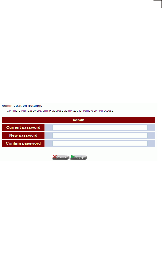
Admin Settings
The Administrative Settings page allows you to configure the management access
password, and IP address(es) authorized for remote management access over the WAN
link.
To protect access to the management interface, you need to configure a new
password as soon as possible. If a new password is not configured, then anyone
having access to the Gateway may be able to compromise the unit's security by
entering the default password.
Management access to the Gateway through the WAN port is enabled by default. To
prevent access by unauthorized hosts, enter the IP address for one or more known
hosts. Once any entry is added to the Remote Management Client List, access
attempts from any other host will be blocked.
Click System, Admin Settings. Set a new password, specify host stations authorized
for remote management access, and click Apply.
Figure 5-13 Admin Settings
Field Attributes
•Current Password – The password for management access. (Default: admin;
Length: 3-16 characters, case sensitive)
•New Password – Prompts you to enter a new password for access.
•Confirm Password – Re-enter the new password.
System Configuration
58
5
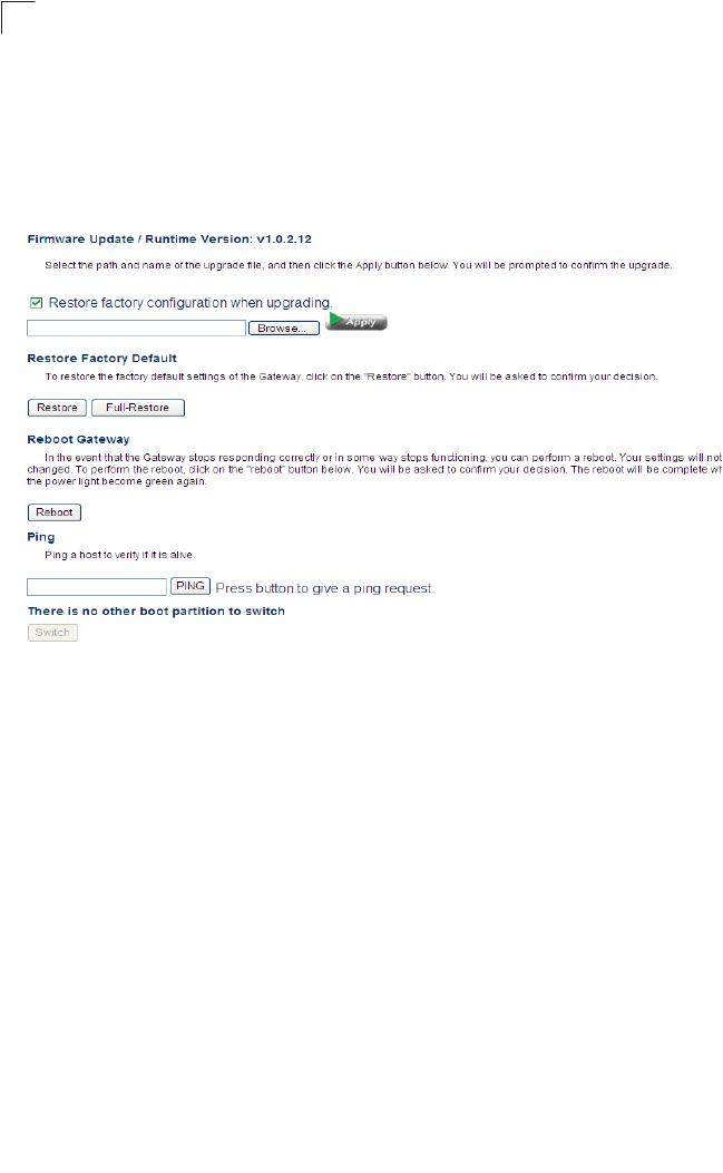
System Tools
This page provides facilities for pinging another device, updating firmware, restoring
factory defaults, and rebooting the unit.
Click System, System Tools. Follow the instructions shown on the web page to
perform any of the listed tasks.
Figure 5-14 System Tools
Field Attributes
•Firmware Update – Allows you to download new firmware by selecting a file stored
on your management station.
•Restore Factory Default – Restores the factory defaults.
•Reboot Gateway – Click the Reboot button to restart the Gateway. When
prompted, confirm that you want reset the Gateway. A timer will display the amount
time remaining in the boot up process.
•Ping – Performs a loopback test on a specified IP address.
System Configuration
59
5
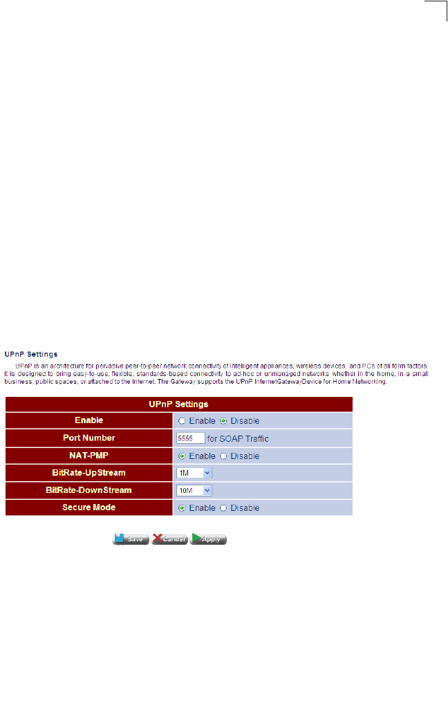
UPnP
This page is used to enable or disable the UPnP auto-discovery mechanism.
Universal Plug and Play (UPnP) is a set of protocols that allows devices to connect
seamlessly and simplifies the deployment of home and office networks. UPnP
achieves this by using UPnP device control protocols designed upon open,
Internet-based communication standards.
Note that only devices within the same broadcast domain can be discovered through
UPnP. When the Gateway is discovered by another device, a brief description of the
Gateway can be viewed, and the management interface can be accessed by
clicking on the Gateway icon.
For example, to access or manage the Gateway with the aid of UPnP under
Windows Vista, open the Network and Sharing Center, and enable Network
Discovery. Then click on the node representing your local network under the
Network Sharing Center. An entry for the Gateway will appear in the list of
discovered devices. Right click on the entry for the Gateway, and select “View
Device webpage” to access the Gateway’s web management interface, or select
“Properties” to display a list of device attributes advertised by the Gateway through
UPnP.
Figure 5-15 UPnP
•EnablePing – Enables UPnP on the unit.
•Port Number – Specifies a port number for SOAP traffic.
•NAT-PMP – Enables/disables NAT Port Mapping Protocol.
•BitRate-UpStream – Specifies the upload speed of your connection. (Default: 1
Mbps; Options: 1 Mbps, 10 Mbps, 100 Mbps)
•BitRate-DownStream – Specifies the download speed of your connection.
(Default: 10 Mbps; Options: 1 Mbps, 10 Mbps, 100 Mbps)
•Secure Mode – Enables/disables secure mode.
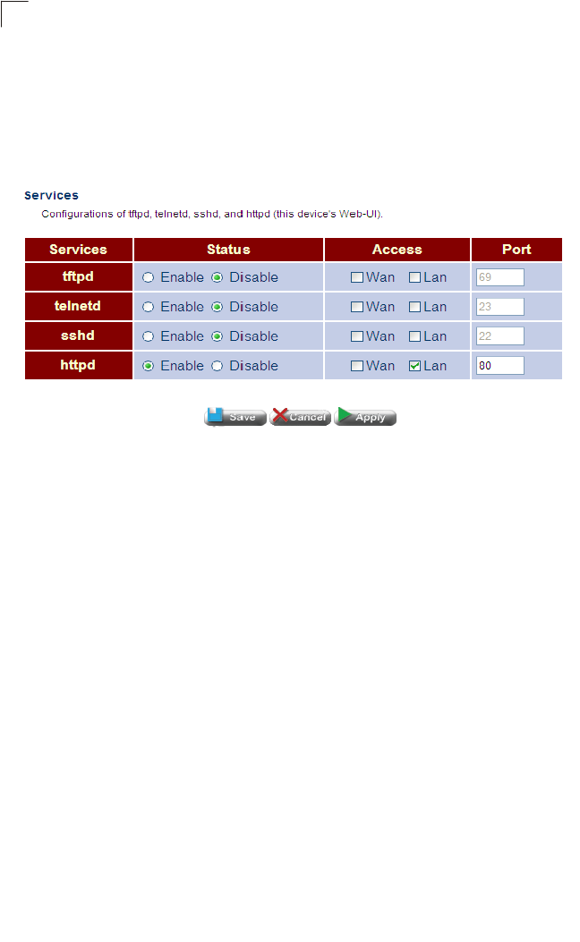
System Configuration
60
5
Service Settings
This page allows you to enable or disable TFTP, Telnet, and Secure Shell access. Note
that these functions are only used for the command line interface, not the web interface.
Click System, Service Settings. Enable or disable the required service, and click
Apply.
Figure 5-16 Service Settings
Field Attributes
•tftpd – Trivial File Transfer Protocol used to download firmware to the Gateway.
•telnetd – Replicates the serial port’s command line interface via Telnet.
•sshd – Replicates the serial port’s command line interface over a secure interface.
When the client contacts the Gateway via the SSH protocol, the Gateway
generates a public-key that the client uses along with a local user name and
password for access authentication. SSH also encrypts all data transfers passing
between the Gateway and SSH-enabled management stations, and ensures that
data traveling over the network arrives unaltered.
•Port – The UDP port number to use for these services. (Range: 0-65535)

System Configuration
61
5
SNMP
Simple Network Management Protocol (SNMP) is a communication protocol
designed specifically for managing devices on a network. Equipment commonly
managed with SNMP includes switches, routers and host computers. SNMP is
typically used to configure these devices for proper operation in a network
environment, as well as to monitor them to evaluate performance or detect potential
problems.
Managed devices supporting SNMP contain software, which runs locally on the
device and is referred to as an agent. A defined set of variables, known as managed
objects, is maintained by the SNMP agent and used to manage the device. These
objects are defined in a Management Information Base (MIB) that provides a
standard presentation of the information controlled by the agent. SNMP defines both
the format of the MIB specifications and the protocol used to access this information
over the network.
The access point includes an onboard agent that supports SNMP versions 1, 2c,
and 3 clients. This agent continuously monitors the status of the access point, as
well as the traffic passing to and from wireless clients. A network management
station can access this information using SNMP management software that is
compliant with MIB II. To implement SNMP management, the access point must first
have an IP address and subnet mask, configured either manually or dynamically.
Access to the onboard agent using SNMP v1 and v2c is controlled by community
strings. To communicate with the access point, the management station must first
submit a valid community string for authentication.
Access to the access point using SNMP v3 provides additional security features that
cover message integrity, authentication, and encryption; as well as controlling
notifications that are sent to specified user targets.
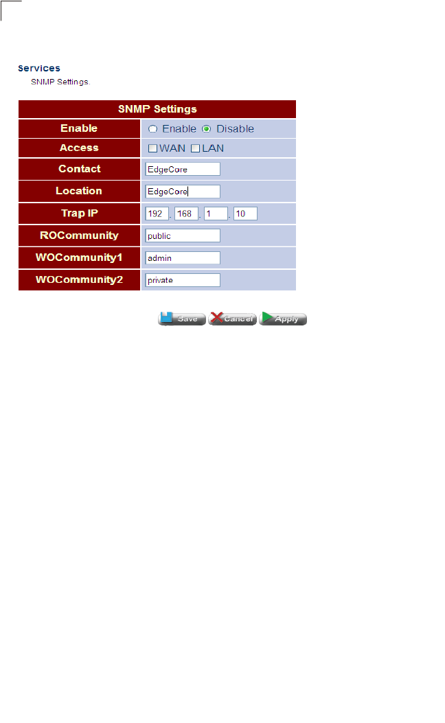
System Configuration
62
5
Figure 5-17 SNMP
•SNMP – Enables or disables SNMP management access and also enables the
access point to send SNMP traps (notifications). (Default: Disable)
•Contact – A text string that describes the system contact. (Maximum length: 255
characters)
•Location – A text string that describes the system location. (Maximum length: 255
characters)
•Trap IP – The IP address of the SNMP server.
•ROCommunity – Defines the SNMP community access string that has read-only
access. Authorized management stations are only able to retrieve MIB objects.
(Maximum length: 23 characters, case sensitive; Default: public)
•WOCommunity1/2 – Defines the SNMP community access string that has write
only access. (Maximum length: 23 characters, case sensitive)
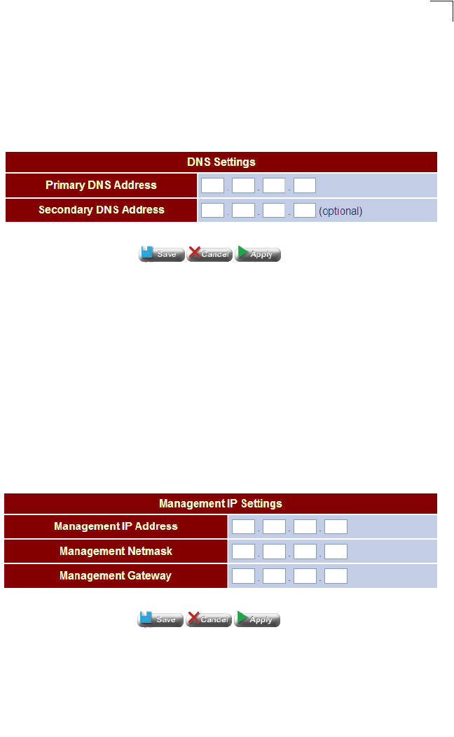
System Configuration
63
5
DNS
The Domain Name System (DNS) distributes the responsibility of assigning domain
names and mapping those names to IP addresses by designating authoritative
name servers for each domain. Authoritative name servers are assigned to be
responsible for their particular domains, and in turn can assign other authoritative
name servers for their sub-domains.
Figure 5-18 DNS
•Primary and Secondary DNS Address – The IP address of Domain Name
Servers on the network. A DNS maps numerical IP addresses to domain names
and can be used to identify network hosts by familiar names instead of the IP
addresses.
If you have one or more DNS servers located on the local network, type the IP
addresses in the text fields provided. Otherwise, leave the addresses as all zeros
(0.0.0.0).
Management IP
The Management IP page configures the IP address through which the unit can be
managed using a web-browser.
Figure 5-19 Management IP
•Management IP Address – The IP address through which the unit can be
managed.
•Management Netmask – Specifies the subnet mask for network traffic.
•Management Gateway – Specifies the gateway address for routing to the unit.
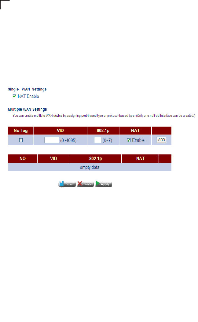
System Configuration
64
5
WAN Configuration
The WAN pages are used to configure the address assignment method for the WAN
interface, and to configure dynamic DNS service.
WAN Type
The WAN Type page allows the user to create multiple WANs by VLAN.
Figure 5-20 WAN Type
•No Tag – Specifies no VLAN tag.
•VID – The VLAN ID.
•NAT – Enables/disables NAT on the specified VLAN.
•Add – Applies the settings and creates the WAN.
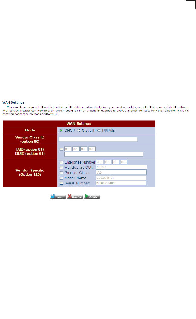
WAN Configuration
65
5
WAN Settings
This page configures address assignment options for the WAN interface, using DHCP, a
static address, or PPPoE. The WAN interface should connect directly to a Layer 3 device
at your service provider’s central office or to another gateway device at your office. You
therefore need to use the method and parameter settings given to you by your service
provider or network administrator.
Dynamic IP Address
Click WAN, WAN Settings. Be sure the WAN interface is enabled. Then select
Dynamic IP Address mode, fill in the appropriate string for the DHCP options as
required, and click Apply.
Figure 5-21 WAN Settings (DHCP)
Field Attributes
•Mode – Select Dynamic IP Address to obtain a address from an upstream DHCP
server.
•Class Identifier (Option 60) – Vendor Class Identifier is used identify the vendor
class and configuration of the Gateway to the DHCP server, which then uses this
information to decide on how to service the client or the type of information to
return.
•Client Identifier (Option 61) – Client Identifier is a unique identifier for the Gateway
which is sent to the DHCP server. DHCP servers use this value to index their
database of address bindings. This value must therefore be unique for all clients in
an administrative domain.
•ENumber (Option 125) – Vendor Idenifying Vendor-Specific Information tag
specified in the form of of a string of numerals xx xx xx xx.
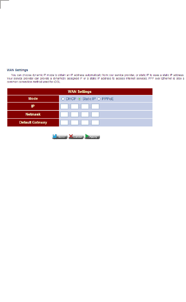
System Configuration
66
5
The general framework for these DHCP options are set out in RFC 2132, but the
specific string to use should be supplied by your service provider or network
administrator.
Static IP Address
Click WAN, WAN Settings. Be sure the WAN interface is enabled. Then select Static
IP Address mode, fill in the appropriate settings as required, and click Apply.
Figure 5-22 WAN Settings (Static)
Field Attributes
•Mode – Select Static IP Address to manually set an address for the Gateway.
•IP – IP address of the WAN interface.
•Netmask – This mask identifies the subnet and host portion of the IP address.
•Default Gateway – The IP address of the gateway router which is used if the
requested destination address is not on the local subnet, nor in any of the routing
tables.
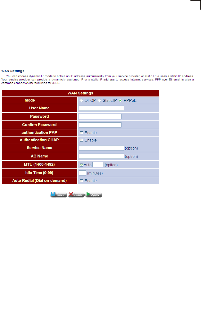
WAN Configuration
67
5
PPPoE
Point-to-Point Protocol over Ethernet (PPPoE) emulates a dial-up connection. It
allows an ISP to use existing network configuration settings to implement VDSL
service without significant changes.
Click WAN, WAN Settings. Be sure the WAN interface is enabled. Then select
PPPoE mode, fill in the appropriate settings as required, and click Apply.
Figure 5-23 WAN Settings (PPPoE)
Field Attributes
•Mode – Select PPPoE to obtain a address using this protocol.
•User Name – Sets the PPPoE user name. (Range: 1-32 characters)
•Password – Sets a PPPoE password. (Range: 1-32 characters)
•Service Name – The service name assigned for the PPPoE connection. The
service name is normally optional, but may be required by some service providers.
(Range: 1-32 alphanumeric characters)
•Confirm Password – Re-enter your new password.
•AC Name – The name of the access concentrator to use in PPPoE Active
Discovery Offers (PADO).
•MTU (1400-1492) – Sets the maximum packet size that the WAN port may
transmit. The Maximum Transmission Unit is expressed in bytes. By default, the
Gateway will send several test messages to determine the MTU for the upstream
connection. (Range: 1400-1492 bytes)
•Idle Time (0-99) – The maximum length of inactive time the unit will stay connected
to the service provider before disconnecting. Select “Auto-reconnect” to reconnect
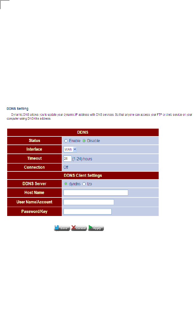
System Configuration
68
5
to the upstream gateway whenever an Internet access request is made.
(Range: 1-99 minutes; Default: 2 minutes)
DDNS
The DDNS Settings page is used to configure dynamic DNS services for DynDNS and
TZO servers. DDNS provides clients accessing the Internet with a method to tie a
specific host name to their computer’s dynamically assigned IP address. DDNS
allows your host name to follow your IP address automatically by changing your
DNS records when your IP address changes. To set up an DDNS account, visit the
web sites of these service providers at www.dyndns.org or www.tzo.com.
Click WAN, DDNS. Enable DDNS, set the timeout, enter the client information
provided by your DDNS service provider, and click Apply.
Figure 5-24 DDNS Settings
Field Attributes
•Status – Enables DDNS. (Default: Disabled)
•Interface – Selects the WAN interface.
•Timeout – The maximum time between updates.
•Connection – Shows if a connection has been established with the DDNS server.
•DDNS Server – The DDNS service provider, DynDNS or TZO.
•Host Name – The prefix to identify your presence on the DDNS server.
•User Name/Account – Your user name for DDNS service.
Password/Key – Your password for DDNS service.
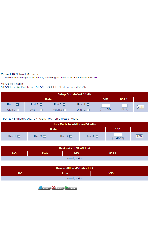
LAN Configuration
69
5
LAN Configuration
The LAN pages are used to configure an IP address for management access
through the LAN interface, configure the local DHCP server, and DNS service.
These pages are also used to configure port connection parameters, including
speed and duplex mode.
LAN Type
LAN Type settings enable VLANs on the units four LAN ports. You may configure up
to four VLANs in total.
Figure 5-25 LAN Type
Field Attributes
•VLAN – Enables or disables VLANs. (Default: Disabled)
•VLAN Type – Selects port-based VLANs by default.
•Port 1~4 – Selects a physical port to apply a VLAN tag to.
•VID – Specifies a VLAN ID. (Range: 0-4095)
•802.1p – Specifies quality of service level.
•Add – Adds the VLAN to the physical port.
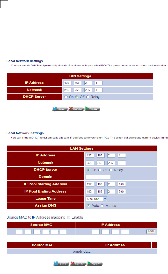
System Configuration
70
5
LAN Settings
This page is used to configure IP settings for the LAN, including an IP address for
management access, a local DHCP server, and DNS service.
Click LAN, LAN Settings. Enable the LAN interface, set an IP address for
management access from the LAN side, configure the DHCP server and DNS
service, then click Apply.
Figure 5-26 LAN Settings
Figure 5-27 LAN Settings (DHCP Enabled)
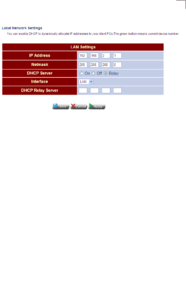
LAN Configuration
71
5
Figure 5-28 LAN Settings (DHCP Relay)
Field Attributes
•IP Address – IP address used for management access from the LAN side.
•Netmask – This mask identifies the subnet and host portion of the IP address.
The following attributes only apply to Router mode:
•DHCP Server – Enables or disables the local DHCP server.
•Domain – DNS suffix appended to unqualified names that are used by this client.
•Class ID – Vendor Class Identifier (Option 60) is used identify the vendor class and
configuration of the client to the DHCP server, which then uses this information to
decide on how to service the client or the type of information to return.
•Client ID – Client Identifier (Option 61) is a unique identifier for the client which is
sent to the DHCP server. DHCP servers use this value to index their database of
address bindings. This value must therefore be unique for all clients in an
administrative domain.
•Option 125 – Vendor Idenifying Vendor-Specific Information tag specified in the
form of of a string of numerals xx xx xx xx.
•IP Pool Starting Address – The initial IP address in a range that the DHCP server
allocates to DHCP clients. Note that the address pool range is always in the same
subnet as the Gateway’s IP address. The maximum clients that the unit can
support is 253.
•IP Pool Ending Address – The ending IP address in a range that the DHCP server
allocates to DHCP clients.
•Lease Time – The amount of time an IP address is leased to the requesting client.
When the time limit expires, the client has to request a new IP address.
•Assign DNS – Specifies whether to use the DNS servers assigned by the DHCP
server, or to manually specify the DNS servers.
•Primary DNS Address – The first server to query for domain name resolution.
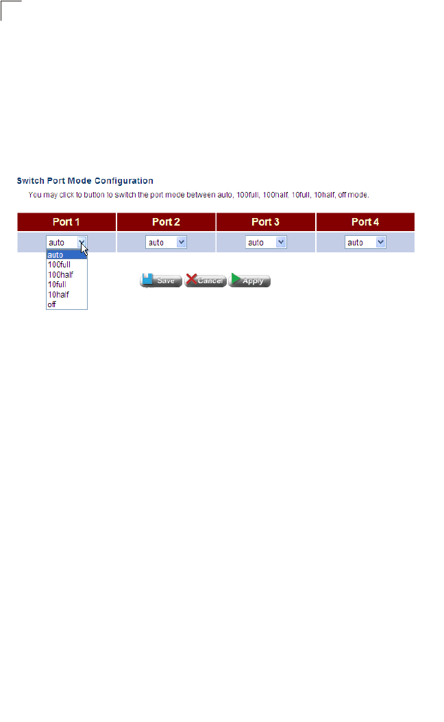
System Configuration
72
5
•Secondary DNS Address – The backup DNS server.
Switch Ports
This page is used to configure port connection parameters, including speed and
duplex mode.
Click LAN, Switch Ports. Set the required connection parameters for any port, and
click Apply.
Figure 5-29 Switch Ports
Field Attributes
•Port – The four ports on the LAN interface.
•Mode – The connection mode for a port.
-auto – Uses auto-negotiation to obtain the optimal settings.
-100full - Forces 100 Mbps full-duplex operation
-100half - Forces 100 Mbps half-duplex operation
-10full - Forces 10 Mbps full-duplex operation
-10half - Forces 10 Mbps half-duplex operation
-off – Disables this port.
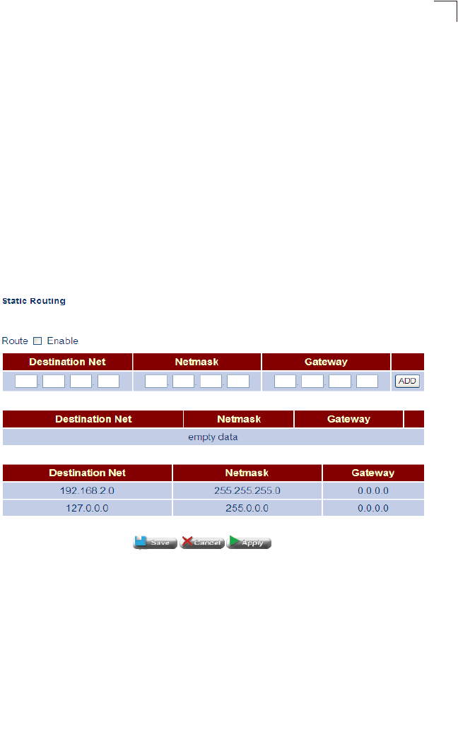
Route Configuration
73
5
Route Configuration
The ROUTE pages are used to configure either static routing entries, or to enable or
disable dynamic routing, or to enable policy routing on the LAN and WAN interfaces.
Static Routing
The Gateway can dynamically configure routes to other network segments using
RIP. However, static routes can also be manually entered in the routing table. Static
routes may be required to access network segments where dynamic routing is not
supported, or can be set to force the use of a specific route to a subnet, rather than
using dynamic routing. Static routes do not automatically change in response to
changes in network topology, so only configure a small number of stable routes to
ensure network accessibility.
Click ROUTE, Static Routing. Enable the static route table, enter the destination
network, the network mask, the gateway device, and click Apply.
Figure 5-30 Static Routing
Field Attributes
•Route – Enables the static routing table.
•Destination Net – IP address of the destination network, subnetwork, or host.
•Netmask – Network mask for the associated IP subnet. This mask identifies the
host address bits used for routing to specific subnets.
•Gateway – IP address of the next router hop used for this route.

System Configuration
74
5
Dynamic Routing
The Gateway supports RIP (also referred to as RIP-1) and RIP-2 dynamic routing
protocols. Routing Information Protocol (RIP) is the most widely used method for
dynamically maintaining routing tables. RIP uses a distance vector-based approach
to routing. Routes are chosen to minimize the distance vector, or hop count, which
serves as a rough estimate of transmission cost. Each router broadcasts its
advertisement every 30 seconds, together with any updates to its routing table. This
allows all routers on the network to build consistent tables of next hop links which
lead to relevant subnets.
RIP can utilize any of the following methods to prevent loops from occurring:
• Split horizon – Never propagate routes back to an interface port from which they
have been acquired.
• Poison reverse – Propagate routes back to an interface port from which they have
been acquired, but set the distance-vector metrics to infinity. (This provides faster
convergence.)
•
Triggered updates – Whenever a route gets changed, broadcast an update message
after waiting for a short random delay, but without waiting for the periodic cycle.
RIP-2 is a compatible upgrade to RIP-1. RIP-2 adds useful capabilities for plain text
authentication, multiple independent RIP domains, variable length subnet masks,
and multicast transmissions for route advertising (RFC 1723).
There are several serious problems with RIP that should be considered. First of all,
RIP-1 has no knowledge of subnets, both RIP versions can take a long time to
converge on a new route after the failure of a link or router during which time routing
loops may occur, and its small hop count limitation of 15 restricts its use to smaller
networks. Moreover, RIP-1 wastes valuable network bandwidth by propagating
routing information through broadcasts; it also considers too few network variables
to make the best routing decision.
If the local network connected to the LAN interface does not include any routers,
then it is not necessary to configure either static or dynamic routing for this interface.
Also, if the path from the Gateway back to the router (that is, the remote gateway) at
the ISP’s central office does not pass through any other routers, then this gateway
will always be the first hop, and again it will not be necessary to configure either
static or dynamic routing.
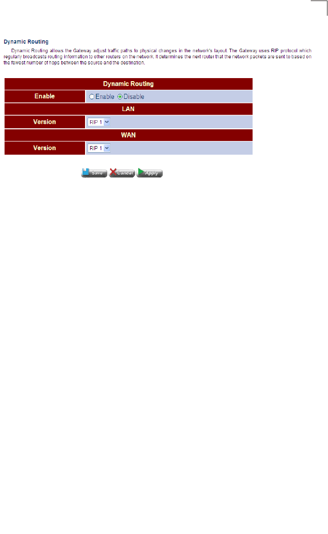
Route Configuration
75
5
Figure 5-31 Dynamic Routing
Field Attributes
•Enable – Enables dynamic routing for both the LAN and WAN interface.
•LAN Version – Specifies RIP-1 or RIP-2 on the LAN interface.
•WAN Version – Specifies RIP-1 or RIP-2 on the WAN interface.
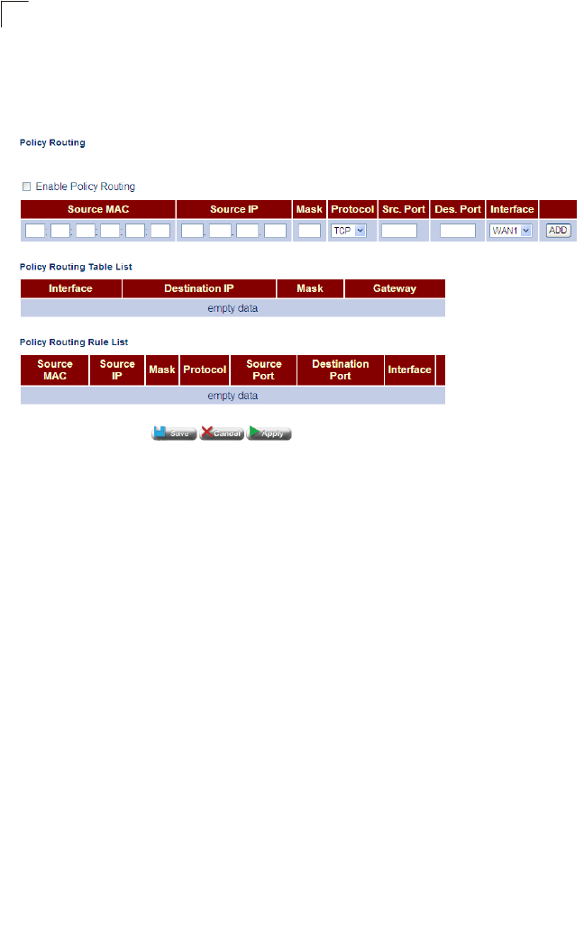
System Configuration
76
5
Policy Routing
Policy routing enables the user to route LAN trafiic to the WAN port according to
source IP, source port, and Protocol.
Figure 5-32 Policy Routing
Field Attributes
•Enable Policy Routing – Enables policy routing to the WAN interface.
•Source IP – Specifies the source IP address.
•Mask – Specifies an IP mask.
•Protocol – Specifies the port type, TCP, UDP or both.
•Src. Port – Specifies the soruce port.
•Des. Port – Specifies the destination port.
•Interface – Specifes the virtual WAN interface.
•Add – Adds the entry to the Policy Routing Rule List.
•Del – Deletes an entry from the Policy Routing List.
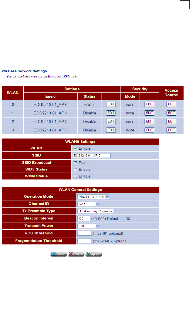
Wireless Configuration
77
5
Wireless Configuration
The IEEE 802.11b/g interfaces include configuration options for radio signal
characteristics and wireless security features.
The unit’s access point function can operate in three modes, mixed 802.11b/g,
802.11b only, or 802.11g. Also note that 802.11g is backward compatible with
802.11b, at slower data transmit rates.
Figure 5-33 Wireless Setup
Field Attributes
•WLAN – Specifies a wireless LAN (WLAN) interface.
•ESSID – The name of the wireless network service provided by the VAP. Clients
that want to connect to the network must set their SSID to the same as that of the
VAP interface. (Default: “ECG9210”; Range: 1-32 characters)

System Configuration
78
5
• Status – Displays whether the wireless interface is enabled or not.
• Mode – Specifies the security mode.
•Access Control – Configures the access control method.
WLAN Settings
• WLAN Enable – Enables the communication for the VAP wireless interface.
• (Default: Enabled)
•SSID – The name of the wireless network service provided by the VAP.
• SSID Broadcast – Enables broadcasting of the SSID to the local wireless network.
(Default: Enabled)
• WDS Status – Enables the WDS status.
WLAN General Settings
• Operation Mode – Defines the radio mode for the VAP interface. (Default:
802.11b/g Mixed)
• Channel ID – The radio channel that the access point uses to communicate with
wireless clients. When multiple access points are deployed in the same area, set
the channel on neighboring access points at least five channels apart to avoid
interference with each other. For example, you can deploy up to three access
points in the same area using channels 1, 6, 11. Note that wireless clients
automatically set the channel to the same as that used by the access point to which
it is linked. Selecting Auto Select enables the access point to automatically select
an unoccupied radio channel.
• Tx Preamble Type – The radio preamble (sometimes called a header) is a section
of data at the head of a packet that contains information that the wireless device
and client devices need when sending and receiving packets. You can set the radio
preamble to long or short. A short preamble improves throughput performance,
whereas a long preamble is required when legacy wireless devices are part of your
network.
• Beacon Interval – The rate at which beacon signals are transmitted from the
access point. The beacon signals allow wireless clients to maintain contact with the
access point. They may also carry power-management information.
(Range: 40-500 TUs; Default: 100 TUs)
•Transmit Power – Adjusts the power of the radio signals transmitted from the
access point. The higher the transmission power, the farther the transmission
range. Power selection is not just a trade off between coverage area and maximum
supported clients. You also have to ensure that high-power signals do not interfere
with the operation of other radio devices in the service area. (Default: Full; Range:
Half, Quarter, One Eigth, Min.)
• RTS Threshold – Sets the packet size threshold at which a Request to Send
(RTS) signal must be sent to a receiving station prior to the sending station starting
communications. The access point sends RTS frames to a receiving station to
negotiate the sending of a data frame. After receiving an RTS frame, the station
sends a CTS (clear to send) frame to notify the sending station that it can start
sending data.

Wireless Configuration
79
5
If the RTS threshold is set to 0, the access point always sends RTS signals. If set
to 2347, the access point never sends RTS signals. If set to any other value, and
the packet size equals or exceeds the RTS threshold, the RTS/CTS (Request to
Send / Clear to Send) mechanism will be enabled.
The access points contending for the medium may not be aware of each other. The
RTS/CTS mechanism can solve this “Hidden Node Problem.” (Range: 0-2346
bytes: Default: none)
• Fragmentation Threshold – Packet Fragmentation can also be used to improve
throughput in noisy/congested situations. Although packet fragmentation is often
thought of as something bad, and does add a large overhead, reducing throughput,
sometimes it is necessary. (Range: 256-2346)
WLAN Security
The unit’s wireless interface is configured by default as an “open system,” which
broadcasts a beacon signal including the configured SSID. Wireless clients with a
configured SSID of “ANY” can read the SSID from the beacon, and automatically set
their SSID to allow immediate connection to the wireless network.
To improve wireless network security, you have to implement two main functions:
• Authentication – It must be verified that clients attempting to connect to the network
are authorized users.
• Traffic Encryption – Data passing between the unit and clients must be protected
from interception and eavesdropping.
For a more secure network, the access point can implement one or a combination of
the following security mechanisms:
• Wired Equivalent Privacy (WEP)
• IEEE 802.1X
• Wi-Fi Protected Access (WPA) or WPA2
The security mechanisms that may be employed depend on the level of security
required, the network and management resources available, and the software
support provided on wireless clients.
WEP Security
WEP provides a basic level of security, preventing unauthorized access to the
network, and encrypting data transmitted between wireless clients and the access
point. WEP uses static shared keys (fixed-length hexadecimal or alphanumeric
strings) that are manually distributed to all clients that want to use the network.
WEP is the security protocol initially specified in the IEEE 802.11 standard for
wireless communications. Unfortunately, WEP has been found to be seriously
flawed and cannot be recommended for a high level of network security. For more
robust wireless security, the access point provides Wi-Fi Protected Access (WPA)
for improved data encryption and user authentication.
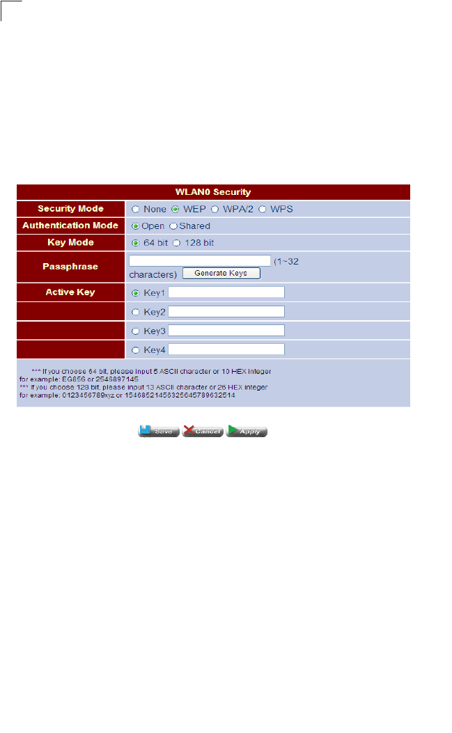
System Configuration
80
5
Setting up shared keys enables the basic IEEE 802.11 Wired Equivalent Privacy
(WEP) on the access point to prevent unauthorized access to the network.
If you choose to use WEP shared keys instead of an open system, be sure to define
at least one static WEP key for user authentication and data encryption. Also, be
sure that the WEP shared keys are the same for each client in the wireless network.
Note that all clients share the same keys, which are used for user authentication and
data encryption. Up to four keys can be specified. These four keys are used for all
VAP interfaces on the same radio.
Figure 5-34 WEP Security
Field Attributes
• Security Mode – Specifies the security mode to be used for authentication.
• Authentication Mode – Specifies open or shared authentication.
• Key Mode – Specifies 64 Bit or 128 Bit security. (Default: 64 bit)
• Passphrase – Specifes a passphrase used for authentication. (Default: none;
Range 1-32 characters)
• Active Key – Specifies a WEP key for authentication.
WPA2 Security
WPA was introduced as an interim solution for the vulnerability of WEP pending the
ratification of the IEEE 802.11i wireless security standard. In effect, the WPA security
features are a subset of the 802.11i standard. WPA2 includes the now ratified
802.11i standard, but also offers backward compatibility with WPA. Therefore, WPA2
includes the same 802.1X and PSK modes of operation and support for TKIP
encryption.
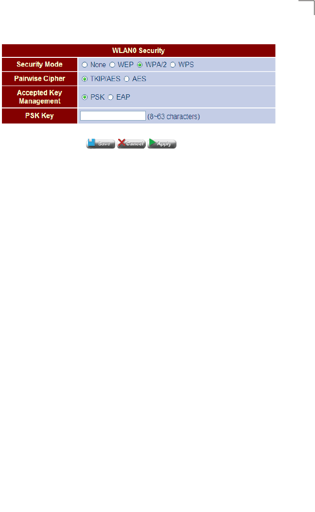
Wireless Configuration
81
5
Figure 5-35 WPA2 PSK Security
Field Attributes
•TKIP/AES – Uses Temporal Key Integrity Protocol (TKIP) or AES keys for
encryption. WPA specifies TKIP as the data encryption method to replace WEP.
TKIP avoids the problems of WEP static keys by dynamically changing data
encryption keys. WPA/WPA2 mixed modes allow both WPA and WPA2 clients to
associate to a common SSID interface. In mixed mode, the unicast encryption
cipher (TKIP or AES-CCMP) is negotiated for each client.
•AES – Uses Advanced Encryption Standard (AES) keys for encryption. WPA2
uses AES Counter-Mode encryption with Cipher Block Chaining Message
Authentication Code (CBC-MAC) for message integrity. The AES Counter-Mode/
CBCMAC Protocol (AES-CCMP) provides extremely robust data confidentiality
using a 128-bit key. Use of AES-CCMP encryption is specified as a standard
requirement for WPA2. Before implementing WPA2 in the network, be sure client
devices are upgraded to WPA2-compliant hardware.
•PSK – Displays the pre-shared key if WPA/WPA2 has been enabled.
•EAP – IEEE 802.1X access security uses Extensible Authentication Protocol
(EAP) and requires a configured RADIUS authentication server to be accessible in
the enterprise network. If you select WPA or WPA2 Enterprise mode, be sure to
configure the RADIUS settings.
•PSK Key – Specifies a pre-shared key. (Default: none; Range: 8-63 characters)
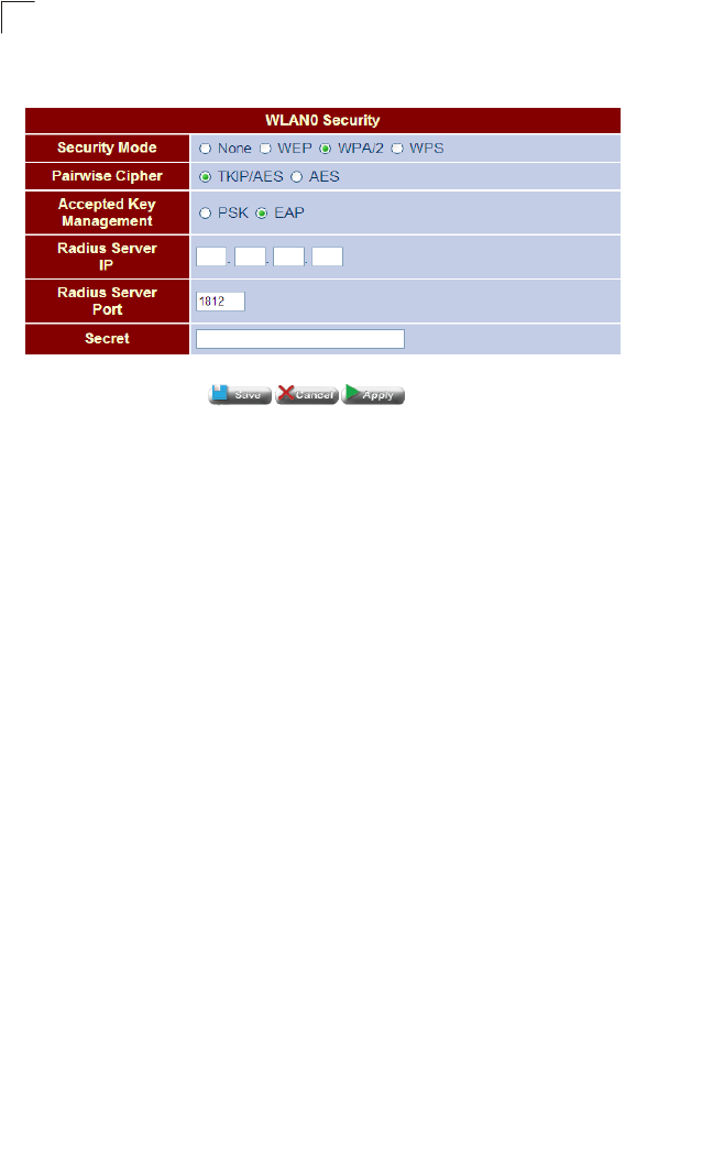
System Configuration
82
5
Figure 5-36 WPA2 EAP Security
Field Attributes
• RADIUS Server IP – Specifies a RADIUS server IP address.
• RADIUS Server Port – Specifies a RADIUS server port number. (Default: 1812)
• Secret – Specifies a secret text string.
WPS Security
The WPS protocol itself consists as a series of EAP message exchanges that is
triggered by a user action and relies on an exchange of descriptive information that
should precede that user's action.
The descriptive information is transferred through a new IE that's added to the
Beacon, Probe Response and optionally to the Probe Request and Association
Request/Response messages. Other than purely informative TLVs, those IEs will
also hold the possible, and the currently deployed, configuration methods of the
device. The WPS IE, has a type field with a value of '221', and OUI of 00-50-F2-04.
The Data part of the IE is constructed out of TLVs that describe the device and its
capabilities.
After the identification of the device's capabilities on both ends, a human trigger is to
initiate the actual session of the protocol. The session consists of 8 messages, that
are followed in the case of a successful session by a message to indicate the
protocol is done. The exact stream of messages may change when configuring
different kinds of devices (AP or STA) or using different physical media (wired or
wireless).
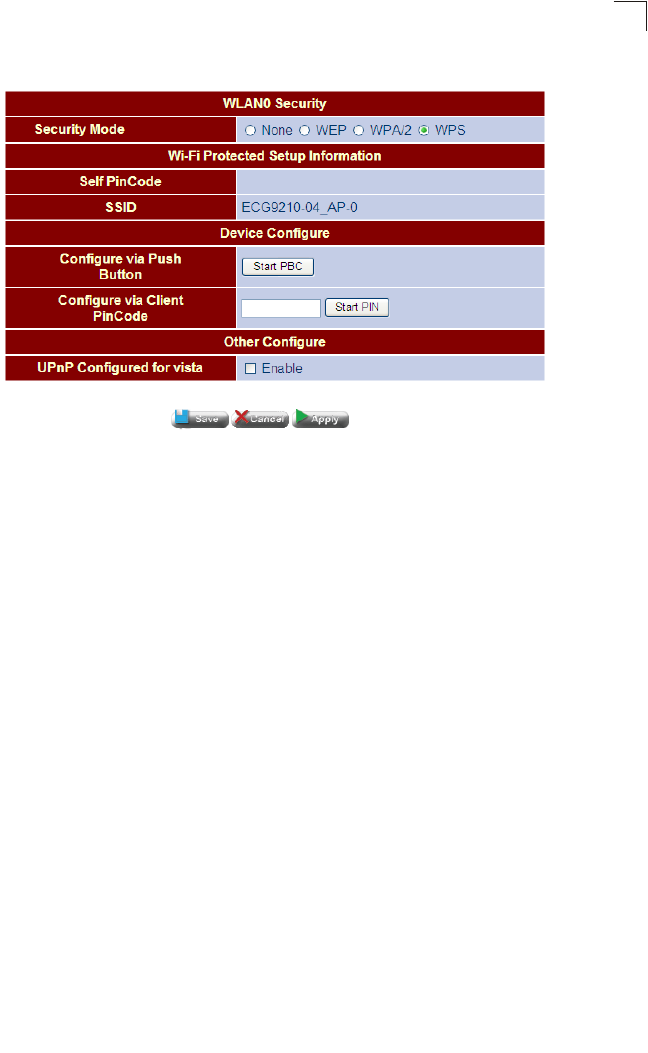
Wireless Configuration
83
5
Figure 5-37 WPS Security
Field Attributes
• Self PinCode – Displays a PIN code for authentication.
•SSID – Displays the SSID.
• Configure via Push Button – Starts a scan for neighboring access points.
• Configure via Client PinCode – Allows the user to enter a PIN code for
authentication.
• UPnP Configured for vista – Enables support for Windows Vista.
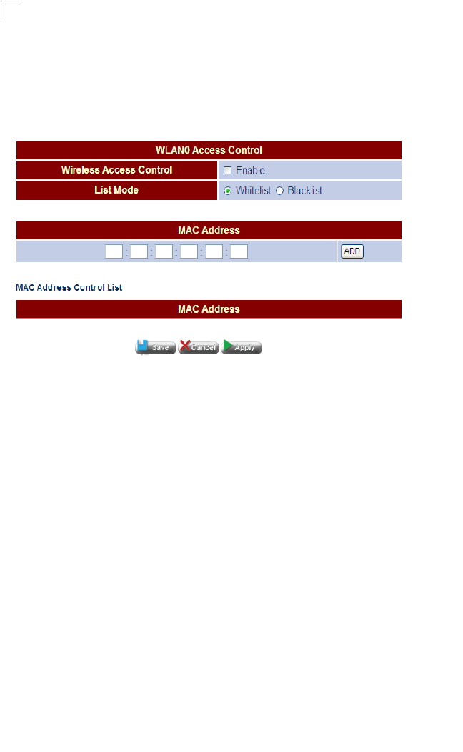
System Configuration
84
5
Access Control
Wireless clients can be authenticated for network access by checking their MAC
address against a local database configured on the access point. You can configure
a list of up to 32 wireless client MAC addresses in the filter list to either allow or deny
network access.
Figure 5-38 Access Control
Field Attributes
•Wireless Access Control – Enables access control.
•List Mode – Specifies whether the MAC address is to be allowed (Whitelist) or
denied (Blacklist).
•MAC Address – Specifies a MAC address to add to the access control list.
•MAC Address Control List – Displays the MAC address entries to be allowed or
denied access to the access point.
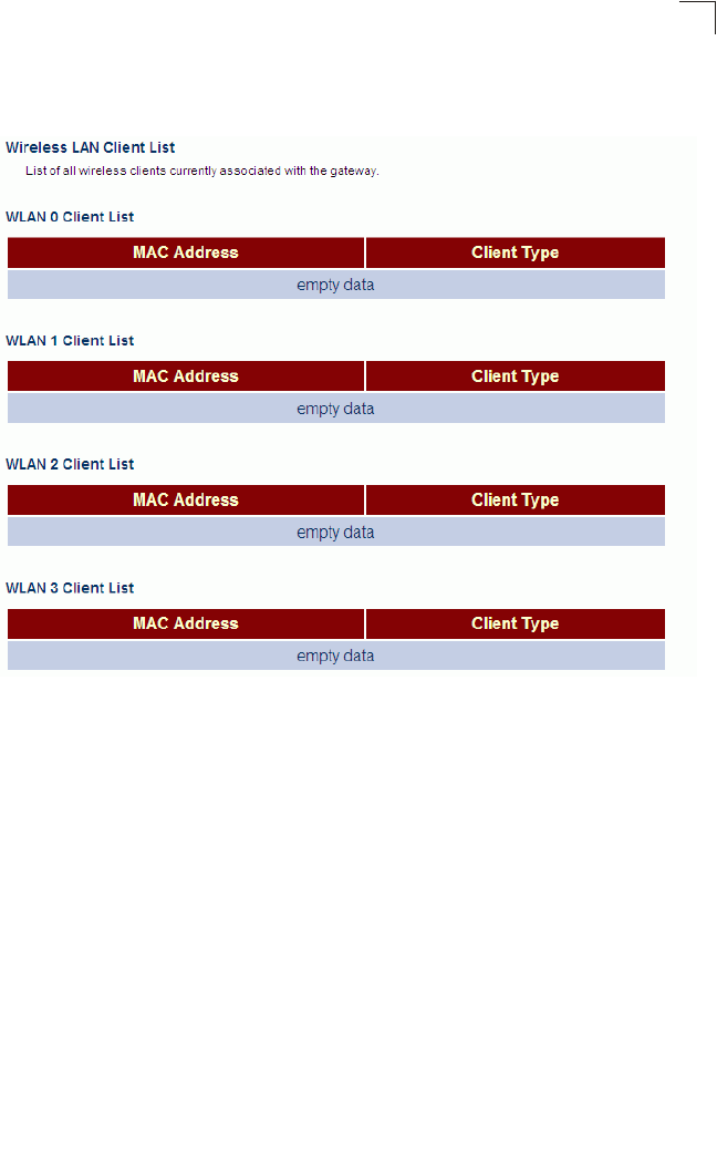
Wireless Configuration
85
5
Client List
The Client List displays all current clients associated with the access point.
Figure 5-39 Client List
Field Attributes
•MAC Address – Displays the MAC address of the currently associated client.
•Client Type – Displays the type of client associated with the access point.

System Configuration
86
5
NAT Configuration
Network Address Translation (NAT) is a method of mapping between a single global
address on the WAN interface to multiple local addresses on the LAN interface. For
the Gateway, the internal (local) IP addresses are those assigned to PCs or other
network devices by the DHCP server, and the external IP address is the single
address assigned to the WAN port.
Virtual Server
If you configure the Gateway as a virtual server, remote users accessing services
such as web sites or FTP servers on your local network through public IP addresses
can be automatically redirected to local servers configured with private IP
addresses. In other words, depending on the requested service (designated by the
TCP/UDP port number), the Gateway redirects the external service request to the
appropriate server (located at an internal IP address). This secures your network
from direct attack by hackers, and provides more flexible management by allowing
you to change internal IP addresses without affecting outside access to local
network services.
For example, if you set Type/Public Port to TCP/80 (HTTP or web) and the Private
IP/Port to 192.168.2.2/80, then all HTTP requests from outside users will be
transferred to 192.168.2.2 on port 80. Therefore, by just entering the IP address
provided by the ISP, Internet users can access the service they need at the local
address to which you redirect them.
The more common TCP service port numbers include: HTTP: 80, FTP: 21,
Telnet: 23, and POP3: 110.
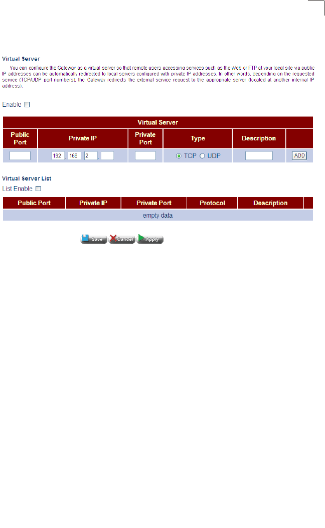
NAT Configuration
87
5
Click NAT, Virtual Server. Specify the IP address of the local server, the private port
number, TCP or UDP type, the public port number, and click Apply.
Figure 5-40 Virtual Server
Field Attributes
•Public Port – Specifies the WAN port number.
•Private IP – The IP address of a server on the local network. The specified address
must be in the same subnet as the Gateway and its DHCP server address pool.
•Private Port – Specifies the local LAN TCP/UDP port number. (Range: 1-65535)
•Type – Specifies the port type, TCP or UDP. (Default: TCP)
•Description – A helpful character string to identify the virtual server.
Port Mapping
Some applications, such as Internet gaming, videoconferencing, Internet telephony
and others, require multiple connections. These applications cannot work with
one-to-one address/port translation. If you need to run applications that require
multiple connections, use port mapping to specify the additional public ports to be
opened for each application.
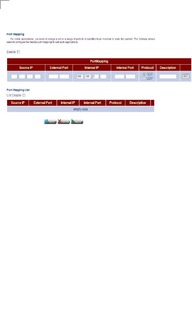
System Configuration
88
5
Click NAT, Port Mapping. Specify the TCP/UDP port range, the IP address of a local
server, and click Apply.
Figure 5-41 Port Mapping
Field Attributes
•Enable – Enables port mapping.
• Port Mapping – Specifies one of two port mapping lists.
• Source IP – Species a source IP address to route from.
• External Port – Specifies an external port, or port range.
• Internal IP – Specifies an internal port to route through.
•Internal Port – Specifies an internal port, or port range.
•Protocol – Specifies the use of a single TCP/UDP port or range of ports.
•Port – A TCP/UDP port or range of ports to assign to a specific application.
•Description – A useful text string that describes the port mapping.
•List Enable – Enables all specified port maps.
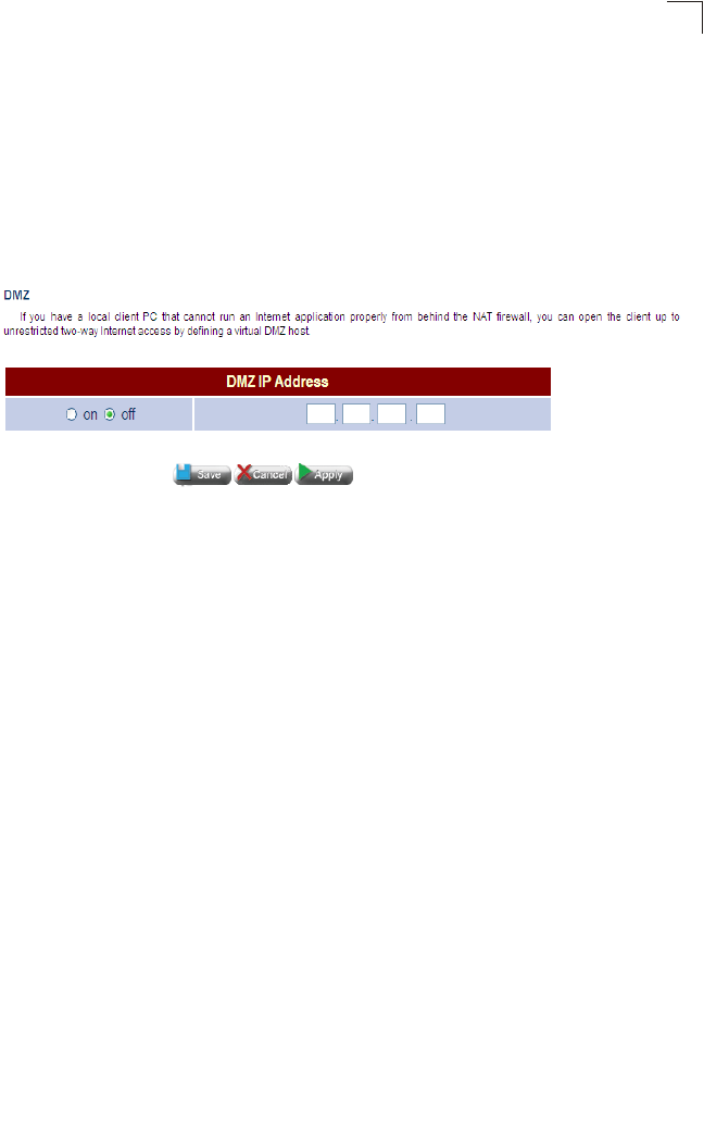
NAT Configuration
89
5
DMZ
This page is used to allow a specified host on the local network to access the
Internet without any firewall protection. Some Internet applications, such as
interactive games or videoconferencing, may not function properly behind the
Gateway’s firewall. By specifying a Demilitarized Zone (DMZ) host, the PC's TCP
ports are completely exposed to the Internet, allowing unrestricted two-way
communications. The host PC should be assigned a static IP address and this
address configured as the DMZ host IP.
Figure 5-42 DMZ
Field Attributes
• DMZ IP Address – Selects one of two IP addresses to enable for DMZ service.
• on/off – Enables/disables the DMZ IP address.
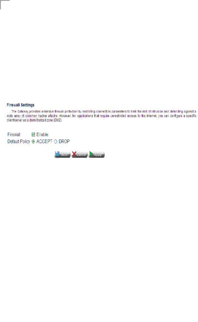
System Configuration
90
5
Firewall Configuration
The Gateway provides extensive firewall protection by restricting connection
parameters to limit the risk of intrusion and defending against a wide array of
common hacker attacks.
Firewall Settings
This page is used to enable or disable the firewall, and set the default forwarding
policy for addresses not found in the MAC or IP filtering list.
Click FIREWALL, Firewall Settings. Enable the firewall, set the default forwarding
policy, and click Apply.
Figure 5-43 Firewall Settings
Field Attributes
•Enable – Enables or disables the firewall. (Default: Disabled)
•Default Policy – Accepts or drops packets not found in the MAC or IP address
filtering tables. (Default: Accept)
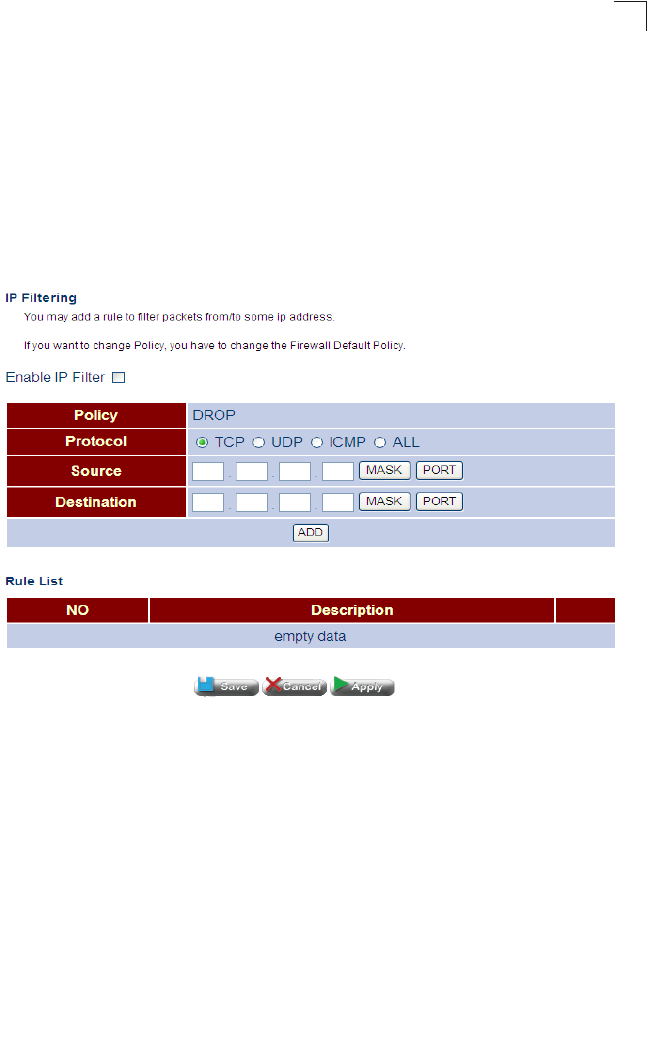
Firewall Configuration
91
5
IP Filtering
This page is used to filter the IP addresses of clients attempting to access the
Internet based on the source or destination IP address and TCP/UDP port of each
packet. Address filtering allows the Gateway to permit or deny specified packets
passing through to the Internet.
Click FIREWALL, IP Filtering. Mark the check box to enable IP address filtering. Set
the addresses to be filtered, the TCP/UDP port, specify whether the matching
packets are to be passed on or dropped, and then click ADD to enter each address
in the table. Once all of the address entries have been specified, click Apply.
Figure 5-44 IP Filtering
Field Attributes
•Policy – Specifies to deny packets matching an entry.
•Enable IP Filter – Enables filtering of all packets in the IP Filtering List.
•Protocol – Specifies a port typem TCP, UDP, ICMP or all.
•Source/Destination – Specifies whether the address is contained in the packet’s
source or destination field.
•Mask – The network prefix which indicates the number of significant bits used to
identify the network portion of the address.
•Port – Specifies the TCP/UDP port number. (Range: 0-65535)
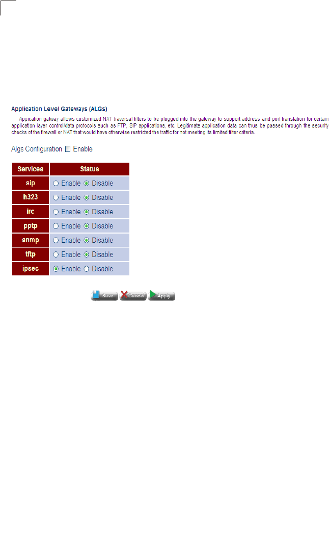
System Configuration
92
5
ALG Configuration
This page is used to enable or disable customized Application Layer Gateway (ALG)
traversal filters for SIP, H323, IRC, PPTP, SNMP, and TFTP applications.
Click FIREWALL, ALG Configuration. Enable ALG traversal filters for the required
applications, and click Apply.
Figure 5-45 ALG Configuration
Field Attributes
•ALG Configuration – Allows Application Layer Gateway (ALG) traversal filters to
be used to support address and port translation for specified application layer
control/data protocols.
•Services – Services for which customized NAT traversal filters are supported.
-SIP – Session Initiation Protocol is used for Internet conferencing, telephony,
events notification and instant messaging.
-H.323 – ITU-T standard that defines protocols used to provide audio-visual
communication sessions on any packet-based network. It is widely deployed by
service providers to support both voice and video services over IP networks.
-IRC – Internet Relay Chat
-PPTP – Point-to-Point Tunneling Protocol is a method for implementing virtual
private networks.
-SNMP – Simple Network Management Protocol.
-TFTP – Trivial File Transfer Protocol.
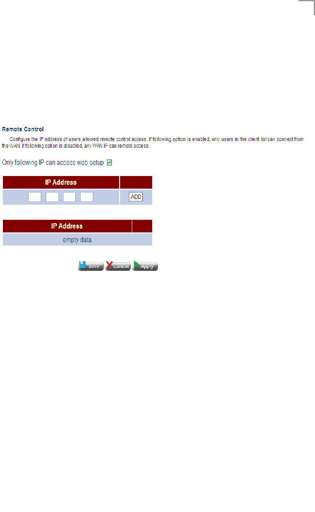
Firewall Configuration
93
5
-IPSEC – Internet Protocol Security is a protocol suite for securing Internet
Protocol (IP) communications by authenticating and encrypting each IP packet
of a data stream.
•Status – Enables or disables filter for specified protocol.
Remote Control
The Remote Control function configures the IP addresses of users who may have
exclusive control of the VDSL/Router from the WAN port.
Figure 5-46 Remote Control
Field Attributes
•Only following IP can access web setup – Enables only specified IP addresses
to have management access of the device.
•IP Address – Specifies an IP address for management access.
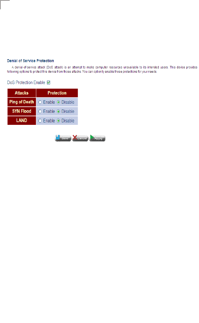
System Configuration
94
5
Denial of Service
A denial-of-service attack (DoS attack) is an attempt to make computer resources
unavailable to its intended users. This device provides following options to protect
this device from those attacks. You can optionlly enable those protections for your
needs.
Figure 5-47 DoS
Field Attributes
•DoS Protection Enable – Enables DoS protection.
•Attacks – Lists the type of DoS attack the unit provides protection from.
•Protection – Enables/disables the DoS for the specified attack.
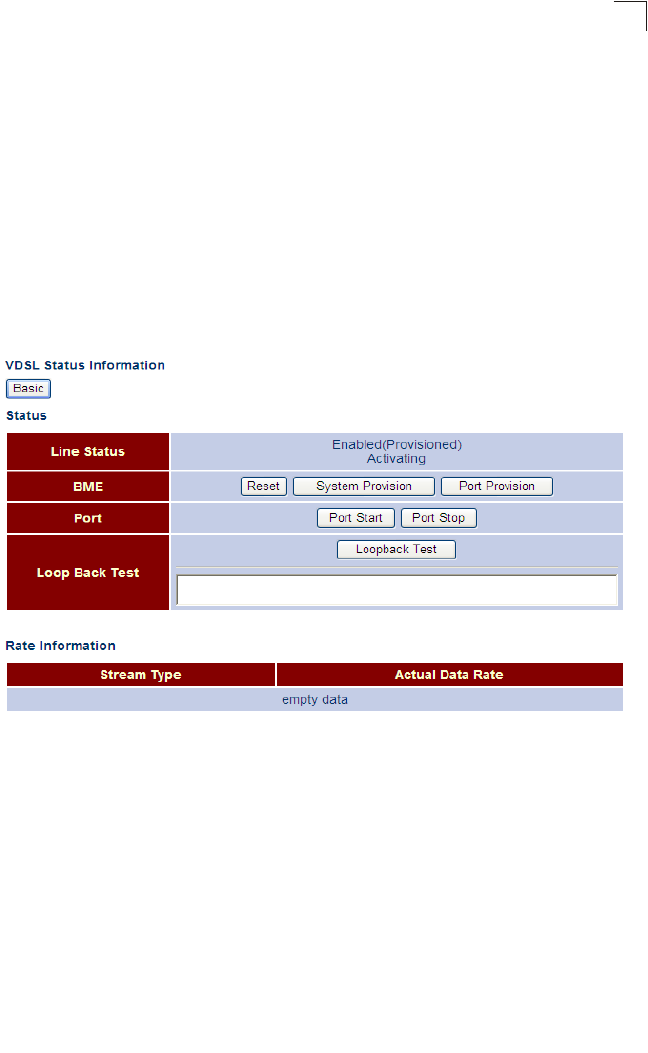
VDSL Configuration
95
5
VDSL Configuration
VDSL connection parameters can be applied globally to all VDSL ports on the
Gateway.
VDSL Status and Rate Information
This page is used to display the status of the VDSL line, provision the BME and
VDSL ports, run loop-back tests for diagnostic purposes; and also to display the
current rate for various stream types and other VDSL line information.
Use any of the functions listed in the VDSL Status table for the System Provision,
Port Provision, or to stop ports. Or display the basic or detailed list of rate
information.
Figure 5-48 VDSL Status and Rate Information
Field Attributes
VDSL Status, Provisioning, Diagnostics
•Line Status – Displays the line status of the VDSL link, including administrative
status, and port state (Activating, Provisioned or Showtime).
•BME – Includes the following OAM functions for the Gateway’s Burst Mode Engine
(that is, VDSL port controller).
-Reset – Resets power to the BME.
-System Provision – Assigns default values to BME system parameters,
including vendor ID for T1/E1 and ITU, revision number, option mask to enable
PM mode, PM alert and diagnostic modes.
-Port Provision – Loads the parameters stored in FLASH to the VDSL port.

System Configuration
96
5
•Port – Starts or stops the VDSL port.
Rate and Line Information
•BME – The number of VDSL ports supported by the BME.
•Downstream/Upstream Line Rate – This rate includes payload (user data) and
any applicable framing overhead.
•Fast Downstream/Upstream Payload Rate – The actual payload carried on the
fast channels.
•Slow Downstream/Upstream Payload Rate – The actual payload carried on the
interleaved channels.
•Downstream Attainable Payload Rate – The maximum rate that can be achieved
in the download direction. This is based on measurements made during line
probing. This rate includes payload (user data) and any applicable framing
overhead.
•Downstream Attainable Line Rate – The maximum attainable line rate on the
downstream channel.
•Downstream/Upstream Line Protection (Slow Path) – The number of additional
DMT symbols added to each packet to increase the noise margin.
•Downstream/Upstream Delay – The maximum interleave delay. Interleaving
causes a delay in the transmission of data. Interleave delay applies only to the
interleave (slow) channel and defines the mapping (relative spacing) between
subsequent input bytes at the interleaver input and their placement in the bit
stream at the interleaver output. Larger numbers provide greater separation
between consecutive input bytes in the output bit stream allowing for improved
impulse noise immunity at the expense of payload latency.
•VDSL Estimated Loop Length – Estimated length of the VDSL connection; used
to calculate power backoff.
•Ghs Estimated Near End Loop Length – Estimated length of the VDSL
connection as viewed from the input receiver on the Gateway; used for
handshaking.
•Ghs Estimated Far End Loop Length – Estimated length of the VDSL connection
as viewed from the central office; used for handshaking.
•Current Framing Mode – Indicates one of the packet framing modes (0: HDLC,
1: EFM, 2: By Pass).
• Band Plan Type –
Table 5-49 VDSL2 Band Plans
Code Band Plan
0x00 BP1_998_3
0x01 BP2_998_3
BP998_3B_8_5M

VDSL Configuration
97
5
•No. of Upstream Bands – This attribute can include both the bands defined by the
Band Plan Configuration setting (see “VDSL Configuration” on page 5-95) and the
optional Upstream Band (US0).
•No. of Downstream Bands – The number of bands defined by the Band Plan
Configuration setting (see “VDSL Status and Rate Information” on page 5-95).
0x02 BP3_998_4
BP998_4B_12M
0x03 BP4_997_3
BP997_3B_7_1M
0x04 BP5_997_3
0x05 BP6_997_4
BP997_4B_7_1M
0x06 BP7_MXU_3
FLEX_3B_8_5M
0x07 BP8_MXU_2
0x08 BP9_998_2
0x09 BP10_998_2
BP998_2B_3_8M
0x0A BP11_998_2
0x0B BP12_998_2
0x0C BP13_MXU_3
0x0D BP14_MXU_3
0x0E BP15_MXU_3
0x0F BP16_997_4B_4P
0x10 BP17_998_138_4400
0x11 BP18_997_138_4400
0x12 BP19_997_32_4400
0x15 BP20_998_138_4400_opBand
0x16 BP21_997_138_4400_opBand
BP22_998_138_4400_opBand
0x17 BP23_998_138_16000
0x18 BP24_998_3B_8KHZ
0x19 BP25_998_138_17600
0x1A BP26_CH1_3
0x1B BP27_CH1_4
Table 5-49 VDSL2 Band Plans (Continued)
Code Band Plan

System Configuration
98
5
Performance Counters
This page is used to display performance information including common error
conditions for the VDSL line.
Figure 5-50 Performance Counters (Basic)
Field Attributes
Basic Performance Counters
•LOF – Loss of Frame. The number of times there was loss of framing error.
•SES – Severely Errored Seconds. The number of second intervals containing 18
or more CRC-8 anomalies, one or more Loss of Signal (LOS) defects, one or more
Severely Errored Frame (SEF) defects, or one or more Loss of Power (LPR)
defects.
•ESE – Excessive Severe Errors. The number of times there were excessive severe
errors.
•LOS – Loss of Signal. The number of times there was a loss of signal error.
•RDI – Remote Defect Indication. The number of times a severely errored frame has
been detected at the far end.
•LOM – Loss of Margin. The number of times there was a loss of noise margin error.
•PO – Power Off failure count. (This parameter only applies to the far end.)
•ES – Errored Seconds. The number of second intervals during which there was
one or more CRC anomalies, or one or more Loss of Signal (LOS) or Loss of
Framing (LOF) defects
•UNAVL_ES – Unavailable Errored Seconds. The number of seconds during which
the VDSL transceiver is powered up but not available.
Field Attributes
Detailed Performance Counters
•TxBlkCnt_S – Count of superframes transmitted on the slow path.
•RxBlkCnt_S – Count of superframes received on the slow path.
•SES – Severely Errored Seconds. The number of second intervals containing 18
or more CRC-8 anomalies, one or more Loss of Signal (LOS) defects, one or more
Severely Errored Frame (SEF) defects, or one or more Loss of Power (LPR)
defects.
•FEC_F – Far end Forward Error Correction on the fast path.
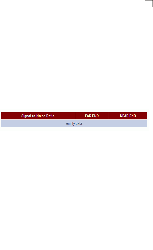
VDSL Configuration
99
5
•CRC_F – Far end CRC errors on the fast path.
•FEC_S – Far end Forward Error Correction on the slow path.
•CRC_S – Far end CRC errors on the slow path.
•LOS – Loss of Signal. The number of times there was a loss of signal error.
•HEC_F – Header Error Control (HEC)/EFM framing errors on the fast path.
•HEC_S – Header Error Control (HEC)/EFM framing errors on the slow path.
•ES – Errored Seconds. The number of second intervals during which there was
one or more CRC anomalies, or one or more Loss of Signal (LOS) or Loss of
Framing (LOF) defects
•UNAVL_ES – Unavailable Errored Seconds. The number of seconds during which
the VDSL transceiver is powered up but not available.
SNR Information
This page is used to display counters for sound-to-noise ratio measurements.
Click VDSL, SNR Information.
Figure 5-51 SNR Information
Field Attributes
•Far End SNR – Sound-to-noise ratio at the far end.
•Avg SNR Margin – Average signal-to-noise margin above the SNR.
•Avg SNR – Average signal-to-noise ratio.
•SNR Margin (SNRMpb0-4) – SNR Margin of band 0-4 in 0.1 dBs.
•Line Attenuation (LATNpb0-4) – Line Attenuation of band 0-4 in 0.1 dBs.
•Signal Attenuation (SATNpb0-4) – Signal Attenuation of band 0-4 in 0.1 dBs.
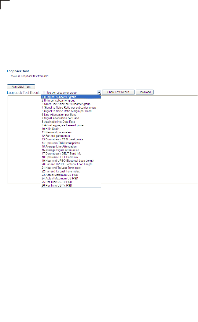
System Configuration
100
5
DELT
Dual-ended loop testing (DELT) is an ITU-standard loop diagnostic tool that enables
the measurement of conditions at both ends of a DSL line. DELT can be used after
deployment to allow service providers to monitor stability and connection rates for
existing customer lines.
Click VDSL, DELT.
Figure 5-52 DELT Loopback Test Information
•Run DELT Test – Performs the selected DELT test.
•DELT Option – The type of signal transmitted from the specified port.
• 1 – H-log per subcarrier group
• 2 – H-lin per subcarrier group
• 3 – Quiet line noise per subcarrier group
• 4 – Signal-to-noise ratio per subcarrier group
• 5 – Signal-to-noise ratio margin per band
• 6 – Line attenuation per band
• 7 – Signal attenuation per band
• 8 – Attainable net data rate
• 9 – Actual aggregate transmit power
• 10 – H-lin scale
• 11 – Near-end parameters
• 12 – Far-end parameters
• 13 – Downstream TSSI breakpoints

IGMP Configuration
101
5
• 14 – Upstream TSSI breakpoints
• 15 – Average line attenuation
• 16 – Average signal attenuation
• 17 – Downstream DELT band information
• 18 – Upstream DELT band information
• 19 – Near end UPBO electrical loop length
• 20 – Far end UPBO electrical loop length
• 21 – Near end TX last tone index
• 22 – Far end TX last tone index
• 23 – Actual maximum DS PSD
• 24 – Actual maximum US PSD
• 25 – Per tone DS Tx PSK
• 26 – Per tone US Tx PSK
•Show Test Result – Displays the DELT test results.
•Download – Downloads the DELT test results to a local folder.
IGMP Configuration
This Gateway can use Internet Group Management Protocol (IGMP) to filter
multicast traffic.
IGMP Snooping can be used to passively monitor or “snoop” on exchanges between
attached hosts and an IGMP-enabled device, most commonly a multicast router. In
this way, the Gateway can discover the ports that want to join a multicast group, and
set its filters accordingly.
Using IGMP Proxy, the Gateway learns multicast requirements from its downstream
interfaces, proxies this group membership information to the upstream router, and
then forwards multicast packets based upon that information to downstream hosts.
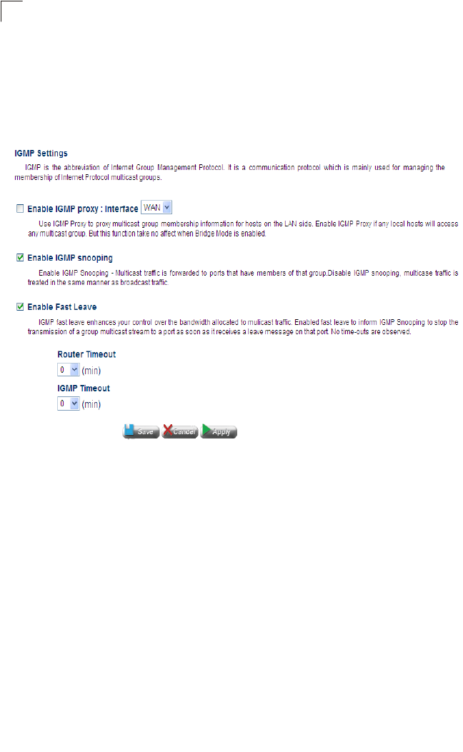
System Configuration
102
5
IGMP Settings
This page is used to configure IGMP Proxy, IGMP Snooping, Fast Leave, and
several other IGMP timeout attributes.
Click IGMP. Enable the required IGMP function, modify any of the timeout attributes
as required, and then click Apply.
Figure 5-53 IGMP Settings
Field Attributes
•Enable IGMP Proxy (Router Mode) – Collects and sends multicast group
membership information onto the upstream interface based on IGMP messages
monitored on downstream interfaces, and forwards multicast traffic based on that
information. (Default: Disabled)
•Enable IGMP Snooping – Passively monitors exchanges between attached hosts
and an IGMP-enabled device (most commonly a multicast router) to discover the
ports that want to join a multicast group, and sets its filters accordingly. (Default:
Enabled)
•Enable Fast Leave – Immediately deletes a member port of a multicast service if
a leave packet is received at that port. (Default: Enabled)
If immediate leave is not used, a multicast router (or querier) will send a
group-specific query message when an IGMPv2 group leave message is received.
The router/querier stops forwarding traffic for that group only if no host replies to
the query.
If immediate leave is enabled, the Gateway assumes that only one host is
connected to the interface. Therefore, immediate leave should only be enabled on

IGMP Configuration
103
5
an interface if it is connected to only one IGMP-enabled device, either a service
host or a neighbor running IGMP snooping.
This attribute is only effective if IGMP snooping is enabled, and IGMPv2 snooping
is used.
•Router Timeout – This function is used to see if IGMP query packets are arriving
from the WAN side at regular intervals, and indicates the time the Gateway waits
after the querier stops before it considers it to have expired. (Option: 0, 1, 5, 10,
20, 30 minutes; Default: 0 minutes, which means that detection is disabled)
If no queries have been detected for the specified time, the Gateway stops
forwarding multicast traffic to downstream clients.
•IGMP Timeout – The function is used to see the IGMP report (join) packets are
arriving from the LAN side at regular intervals, and indicates the time the Gateway
waits after these messages have stopped before it considers there to be no more
downstream clients. (Options: 0, 1, 5, 10, 20, 30 minutes; Default: 0 minutes, which
means that detection is disabled)
If no report message have been detected for the specified time, the Gateway stops
forwarding multicast traffic to downstream clients.
When an IGMPv2 or v3 multicast host leaves a group, it sends an IGMP leave
message. When the leave message is received by the Gateway, it checks to see
if this host is the last to leave the group by sending out an IGMP group-specific or
group-and-source-specific query message, and starts a timer. If no reports are
received before the timer expires, the group record is deleted, and a report is sent
to the upstream multicast router.
Since IGMPv1 clients do not send leave packets, both Router Timeout and IGMP
Timeout are required to maintain multicast flows to IGMPv1 clients.
This attribute will take effect only if Fast Leave is enabled.
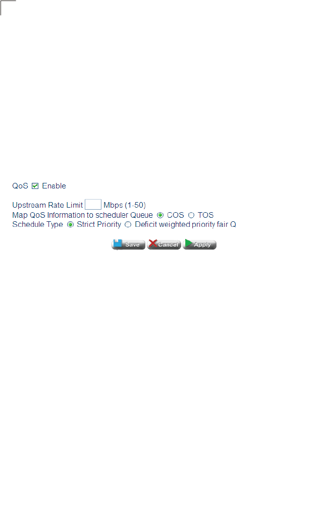
System Configuration
104
5
QoS Configuration
Quality of Service (QoS) specifies which data packets have greater precedence
when traffic is buffered in the Gateway due to congestion. The Gateway supports
QoS with eight priority queues for each port. Data packets in a port’s high-priority
queue will be transmitted before those in the lower-priority queues.
QoS Settings
This page is used to enable or disable QoS, sets the upstream rate limit, and the
queuing mode.
Click QoS, QoS Settings. Enable QoS, specify the maximum upstream data rate,
select the queueing method, and then click Apply.
Figure 5-54 QoS Settings
Field Attributes
•QoS Enable – Enables or disables QoS settings.
•Upstream Rate Limit – Sets the maximum rate for traffic transmitted onto the
upstream interface. Traffic that falls within the rate limit is transmitted, while
packets that exceed the acceptable amount of traffic are dropped.
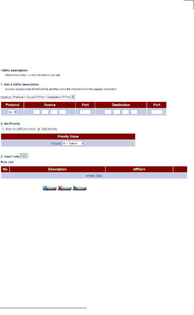
QoS Configuration
105
5
Traffic Classification
This page is used to configure diffServ priorities based on protocol type, source and
destination addresses, and TCP/UDP port.
Click QoS, Traffic Classification. Select the classification method from the
drop-down list and fill in the required parameters, set the priority, click ADD to insert
the rule in the table, and then click Apply.
Figure 5-55 Traffic Classification
Field Attributes
•Method
-Protocol – Specifies the protocol type to match as TCP or UDP.
-Source Port – Source port number1 (that is, protocol socket number) for the
specified protocol type.
-Source IP/Port – Source IP address, and port number1 for the specified protocol
type.
-Destination Port – Destination port number1 for the specified protocol type.
-Source IP/Port – Destination IP address, and port number1 for the specified
protocol type.
-Protocol + Source IP/Port + Destination IP/Port – Source/destination IP
address, and port number1 for the specified protocol type.
1. The TCP/UDP port range is 0-65535.

System Configuration
106
5
•Priority
-CS Class – Class of Service (CoS) priority.
(Range: 0 - 7, where 7 is the highest priority: Default: 0)
This Gateway processes Class of Service (CoS) priority tagged traffic by using
eight priority queues for each port. Up to eight separate traffic priorities are
defined in IEEE 802.1p. The default priority levels are assigned according to
recommendations in the IEEE 802.1p standard as shown in the following table.
The priority levels recommended in the IEEE 802.1p standard for various
network applications are shown in the following table. However, you can map the
priority levels to the Gateway’s output queues in any way that benefits
application traffic for your own network.
-PHB – Per-Hop Behavior includes the following DiffServ queueing options:
- Best-Effort uses the lowest priority. BE (DSCP, Q=0)
- Assured Forwarding provides four priority classes. AF1X(DSCP,Q=1),
AF2X (DSCP, Q=2), AF3X (DSCP, Q=3), AF4X (DSCP, Q=4)
- Expedited Forwarding provides highest priority. EF (DSCP, Q=5)
-PHB Priority – Per-hop behavior, or the priority used for this router hop.
(Range: 0-7, where 7 is the highest priority)
Table 5-56 Mapping CoS Values to Egress Queues
Priority 01234567
Queue 20134567
Table 5-57 CoS Priority Levels
Priority Level Traffic Type
1Background
2 (Spare)
0 (default) Best Effort
3 Excellent Effort
4 Controlled Load
5 Video, less than 100 milliseconds latency and jitter
6 Voice, less than 10 milliseconds latency and jitter
7 Network Control
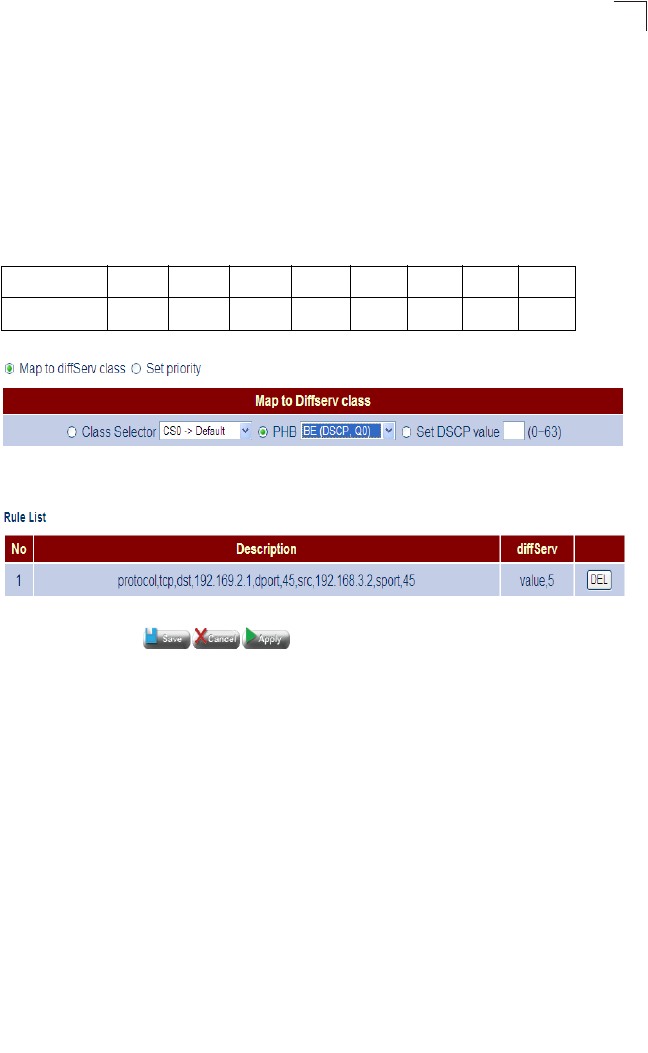
QoS Configuration
107
5
DSCP to 802.1p Mapping
Use the DSCP to 802.1p page to assign Class of Service (CoS) values to the priority
queues (i.e., hardware output queues 0 - 3) on the CPE.
Most CPEs currently support Class of Service by using four priority queues, with
Weighted Round Robin queuing for each port. Eight separate traffic classes are
defined in IEEE 802.1p. The default priority levels are assigned as shown below.
Figure 5-58 DSCP to 802.1p Mapping
Figure 5-59 DSCP to 802.1p Default Mapping
Field Attributes
•Enable – Enables DSCP to 802.1p mapping.
•DSCP start – Specifies the DSCP start priority.
•DSCP end – Specifies the DSCP end priority.
•802.1p – Specifies the 802.1p CoS priority.
Table 5-1 Default CoS Priority Levels
Priority 01234567
Queue 00112233
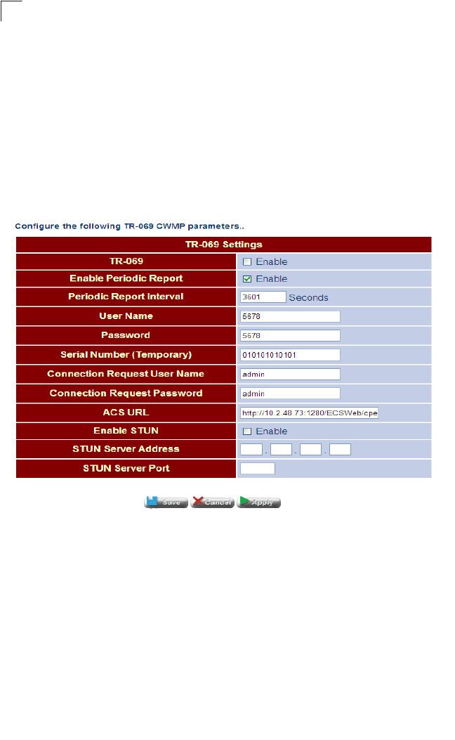
System Configuration
108
5
ACS Configuration
Configures parameters for auto-configuration servers (ACS) based on TR-069 (CPE
WAN Management Protocol) and TR-098 (Internet Gateway Device Data Model for
TR-069 Configuration).
TR Settings
This page is used to configure parameters for establishing a connection between the
Gateway and an auto-configuration server.
Click TR. Configure the required parameters, and click Apply.
Figure 5-60 TR Settings
Field Attributes
•TR – Enables or disables connection with an auto-configuration server upon initial
bootup and at the specified periodic report interval or when events occur that must
be reported to the ACS (such as when the broadband IP address of the Gateway
changes). When this parameter is enabled, the ACS can also issue a Connection
Request to the Gateway at any time, instructing it to establish a communication
session with the ACS.
•Enable Periodic Report – Enables periodic reporting of status and performance
information, as well as information used to diagnose connectivity and service
issues.
•Periodic Report Interval – The interval at which the Gateway must initiate a
connection session with the ACS.

ACS Configuration
109
5
•User Name – A string used to identify the Gateway during authentication with the
ACS. This string should be globally unique among all CPE manufacturers.
Specifically it should be a multi-part string comprising a manufacturer identifier and
a serial number unique within that manufacturer. The recommended format for this
string is OUI-SERIAL, where OUI is a six-digit hexadecimal value using all
upper-case letters and including any leading zeros. (Range: 1-6 characters)
•Password – A user name used to authenticate the Gateway when it attempts to
make a connection with the ACS as defined in the CPE WAN Management
Protocol. (Range: 1-256 characters)
This user name is used only for HTTP-based authentication of the Gateway.
Note that on a factory reset of the Gateway, this parameter is reset to its factory
value. If an ACS modifies the value of this parameter, it should take into account
the fact that the original value will be restored as the result of a factory reset.
• Serial Number (Temporary) – A temporary serial number to uniquely identify the
unit’s TR connection.
•Connection Request User Name – A user name used to authenticate an ACS
when requesting the Gateway to establish a connection with it. (Range: 1-256
characters)
•Connection Request Password – A password used to authenticate an ACS when
requesting the Gateway to establish a connection with it. (Range: 1-256
characters)
•ACS URL – HTTP or HTTPS URL that uniquely identifies the ACS.
•Enable STUN – Simple Traversal of UDP through NATs.
Enables the use of STUN by the Gateway. This applies only to the use of STUN in
association with the ACS to allow UDP Connection Requests. Some applications
have difficulty connecting through a firewall to remote servers. If you experience
this kind of problem connecting to the ACS, the use of a STUN server may be
required to determine the IP address allocated to this application by the NAT.
•STUN Server Address – Host name or IP address of the STUN server to which
the Gateway sends binding requests when STUN is enabled. If this field is empty
and STUN is enabled, the Gateway must use the address of the ACS extracted
from the host portion of the ACS URL.
•STUN Server Port – Port number of the STUN server to which the Gateway sends
binding requests if STUN is enabled.
•Root CA File – The root file used in certificate-based authentication. This file is
used by the Gateway to identify the ACS. Note that because this authentication
process uses SSL/TLS, the ACS URL attribute on this page must be specified as
an HTTPS URL.
•Client Certificate File – Filename of the client’s digital certificate. This file is used
by the ACS to identify the Gateway.
•Client Private Key File – A digital file used for message decryption, and to form
digital signatures.

System Configuration
110
5

111
Appendix A: Troubleshooting
Diagnosing Gateway Indicators
Gateway operation is easily monitored via the LED indicators to identify problems. The
table below describes common problems you may encounter and possible solutions. If
the solutions in the table fail to resolve the problem, contact technical support for
advice.
Table A-1 Troubleshooting Chart
Symptom Cause Solution
PWR
indicator does not
light up after power
on.
Power outlet, power
cord, or external
power adapter may be
defective.
• Check the power outlet by plugging in another
device that is functioning properly.
• Check the power adapter with another Gateway.
LAN
link indicator does
not light up after
making a connection.
Network interface
(e.g., a network
adapter card in the
attached computer),
network cable, or
Gateway LAN port
may be defective.
• Verify that the Gateway and computer are
powered on.
• Be sure the cable is plugged into both the
Gateway and the computer.
• Verify that the proper cable type is used and its
length does not exceed specified limits.
• Check the network adapter in the computer and
cable connections for possible defects. Replace
the defective adapter or cable if necessary.
VDSL LINK
indicator is off or
does not stop
flashing (i.e.,
synchronizing) after
making a connection.
VDSL switch, cabling,
or Gateway VDSL
port may be defective.
• Verify that the Gateway and attached VDSL
switch are powered on.
• Be sure the cable is plugged into both the
Gateway and an RJ-11 telephone jack.
• Verify that the cable length does not exceed
specified limits. (Check with your service
provider for this information.)
• Check the cable connections on the Gateway,
wall jack, punch-down block/patch panel, and
the VDSL switch for possible defects. Replace
the defective cable if necessary.
ALARM
indicator is on. VDSL link failure Restart the Gateway. If condition is not resolved,
contact your service provider.

Troubleshooting
112
A
If You Cannot Connect to the Internet
• Check that your computer is properly configured for TCP/IP. See “Configuring the
TCP/IP Protocols” on page 27.
• Make sure the correct network adapter driver is installed for your PC operating
system. If necessary, try reinstalling the driver.
• Check that the network adapter’s speed or duplex mode has not been configured
manually. We recommend setting the adapter to auto-negotiation when installing the
network driver.
Problems Accessing the Management Interface
Table A-1 Troubleshooting Chart
Symptom Action
Cannot connect using Telnet,
web browser, or SNMP
software
• Be sure the Gateway is powered up.
• Check the network cabling between the management station and the
Gateway.
• Check that you have a valid network connection to the Gateway and that
the port you are using has not been disabled.
• Be sure you have configured the VLAN interface through which the
management station is connected with a valid IP address, subnet mask
and default gateway.
• Be sure the management station has an IP address in the same subnet as
the Gateway’s IP interface to which it is connected.
• If you cannot connect using Telnet*, you may have exceeded the
maximum number of concurrent Telnet/SSH sessions permitted. Try
connecting again at a later time.
* Telnet and SSH are not implemented for the current firmware, but will be made available for future releases.
Cannot connect using
Secure Shell • If you cannot connect using SSH*, you may have exceeded the maximum
number of concurrent Telnet/SSH sessions permitted. Try connecting
again at a later time.
•Be sure the control parameters for the SSH server are properly configured
on the Gateway, and that the SSH client software is properly configured
on the management station.
Forgot or lost the password • Contact your local distributor.
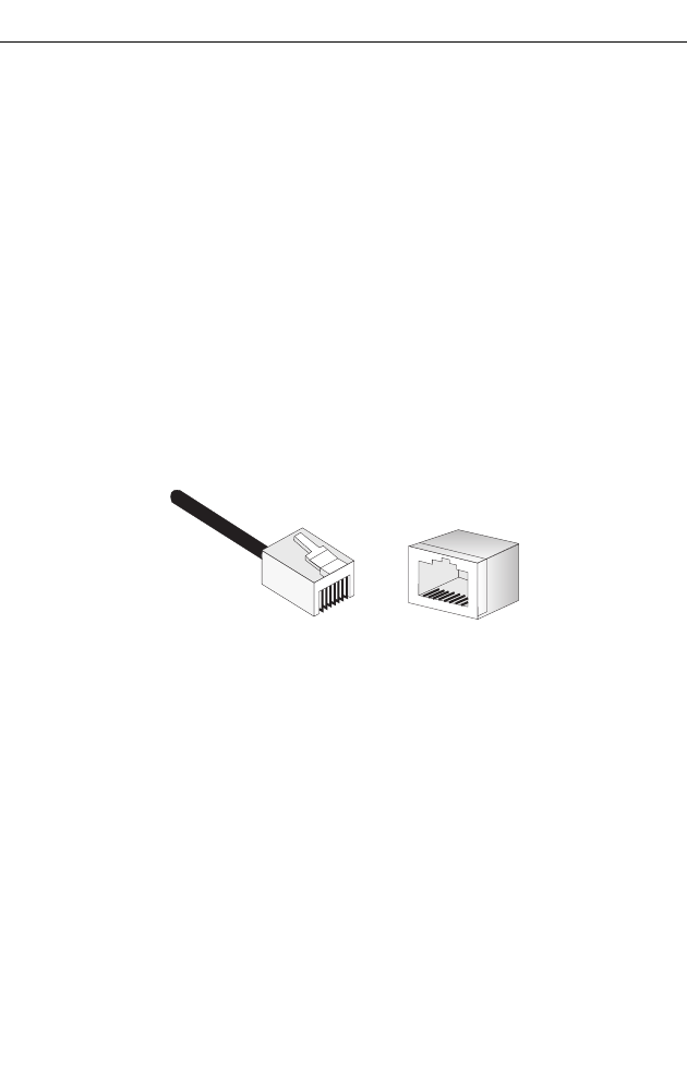
113
Appendix B: Cables
Twisted-Pair Cable and Pin Assignments
For 10BASE-T and 100BASE-TX connections, the twisted-pair cable must have two
pairs of wires. Each wire pair is identified by two different colors. For example, one
wire might be green and the other, green with white stripes. Also, an RJ-45
connector must be attached to both ends of the cable.
Caution: DO NOT plug a phone jack connector into any RJ-45 port. Use only
twisted-pair cables with RJ-45 connectors that conform with FCC standards.
Caution: Each wire pair must be attached to the RJ-45 connectors in a specific
orientation. (See “10BASE-T/100BASE-TX Pin Assignments” on page 113 for
an explanation.)
The figure below illustrates how the pins on the RJ-45 connector are numbered. Be
sure to hold the connectors in the same orientation when attaching the wires to the
pins.
Figure B-1 RJ-45 Connector Pin Numbers
10BASE-T/100BASE-TX Pin Assignments
Use unshielded twisted-pair (UTP) or shielded twisted-pair (STP) cable for RJ-45
connections: 100-ohm Category 3, 4 or 5 cable for 10 Mbps connections, or
100-ohm Category 5 cable for 100 Mbps connections. Also be sure
that the length of
any twisted-pair connection does not exceed 100 meters (328 feet).
The RJ-45 ports on the Gateway support automatic MDI/MDI-X operation, so you
can use straight-through cables for all network connections to PCs or gateways. In
straight-through cable, pins 1, 2, 3, and 6, at one end of the cable, are connected
straight through to pins 1, 2, 3, and 6 at the other end of the cable. When using the
RJ-45 port on this Gateway, you can use either straight-through or crossover cable.
81
1
8
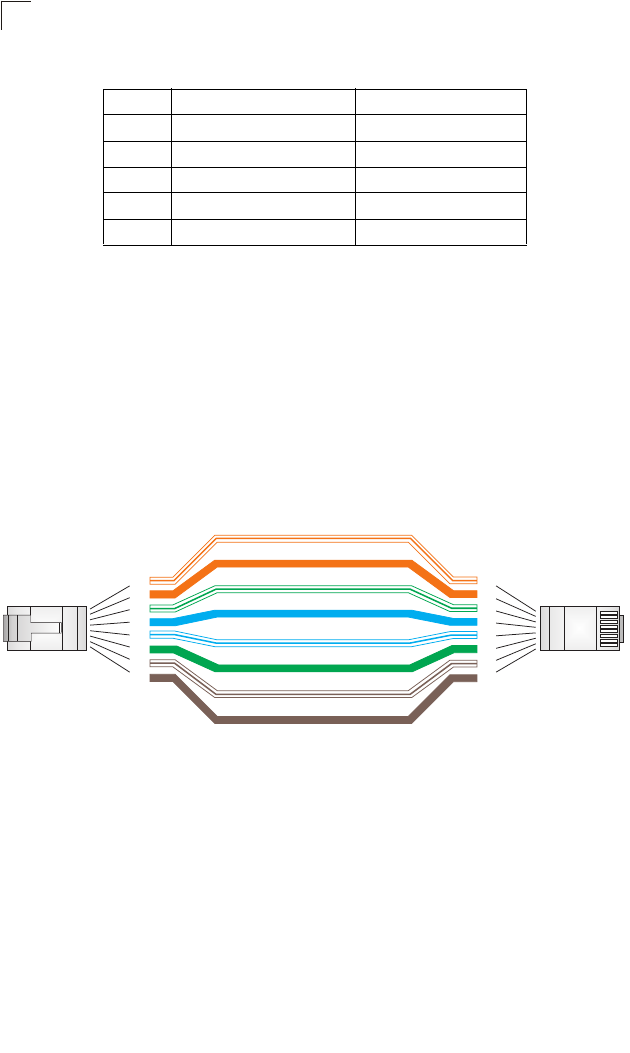
114
Cables
B
Straight-Through Wiring
If twisted-pair cable is to join two ports and only one of the ports has an internal
crossover (MDI-X), the two pairs of wires must be straight-through. (When
auto-negotiation is enabled for the RJ-45 port on the Gateway, you can use either
straight-through or crossover cable to connect to any device type.)
Figure B-2 Straight-through Wiring
Table B-1 10BASE-T/100BASE-TX MDI and MDI-X Port Pinouts
Pin MDI Signal Name MDI-X Signal Name
1 Transmit Data plus (TD+) Receive Data plus (RD+)
2 Transmit Data minus (TD-) Receive Data minus (RD-)
3 Receive Data plus (RD+) Transmit Data plus (TD+)
6 Receive Data minus (RD-) Transmit Data minus (TD-)
4,5,7,8 Not used Not used
Note: The “+” and “-” signs represent the polarity of the wires that make
up each wire pair.
White/Orange Stripe
Orange
White/Green Stripe
Green
1
2
3
4
5
6
7
8
1
2
3
4
5
6
7
8
EIA/TIA 568B RJ-45 Wiring Standard
10/100BASE-TX Straight-through Cable
End A End B
Blue
White/Blue Stripe
Brown
White/Brown Stripe
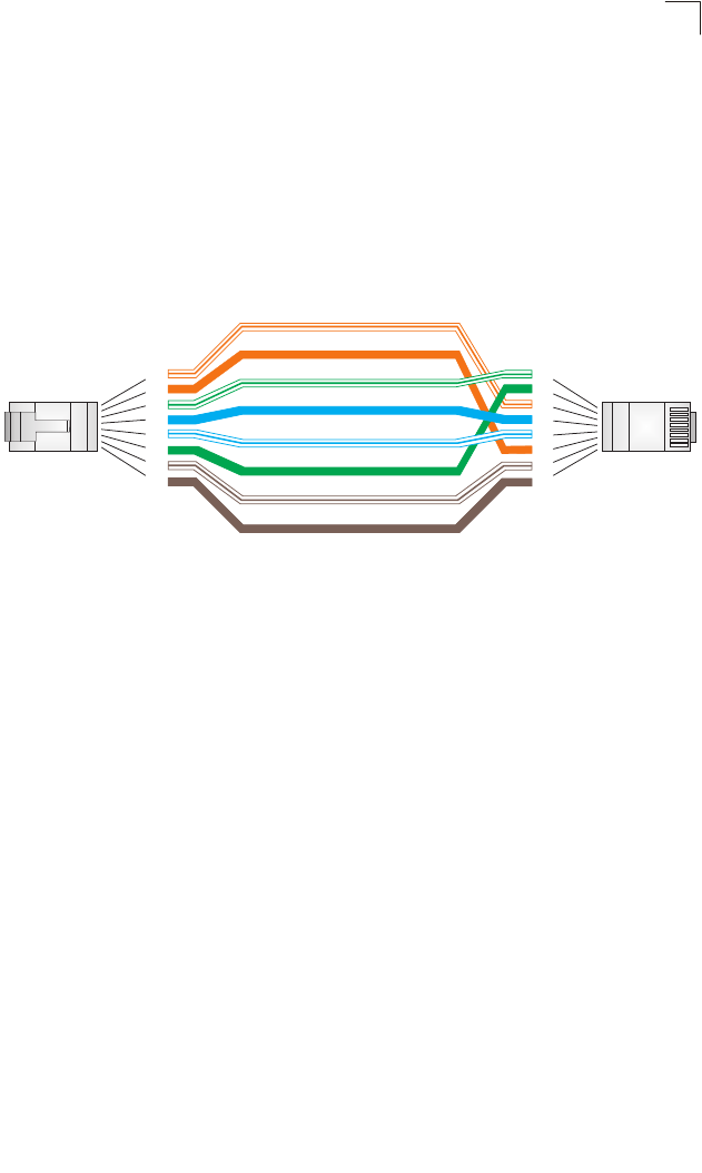
115
Twisted-Pair Cable and Pin Assignments
B
Crossover Wiring
If the twisted-pair cable is to join two ports and either both ports are labeled with an
“X” (MDI-X) or neither port is labeled with an “X” (MDI), a crossover must be
implemented in the wiring. (When auto-negotiation is enabled for the RJ-45 port on
the Gateway, you can use either straight-through or crossover cable to connect to
any device type.)
Figure B-3 Crossover Wiring
Cable Testing for Existing Category 5 Cable
Installed Category 5 cabling must pass tests for Attenuation, Near-End Crosstalk
(NEXT), and Far-End Crosstalk (FEXT). This cable testing information is specified in
the ANSI/TIA/EIA-TSB-67 standard. Additionally, cables must also pass test
parameters for Return Loss and Equal-Level Far-End Crosstalk (ELFEXT). These
tests are specified in the ANSI/TIA/EIA-TSB-95 Bulletin, “The Additional
Transmission Performance Guidelines for 100 Ohm 4-Pair Category 5 Cabling.”
Note that when testing your cable installation, be sure to include all patch cables
between switches and end devices.
White/Orange Stripe
Orange
White/Green Stripe
1
2
3
4
5
6
7
8
1
2
3
4
5
6
7
8
EIA/TIA 568B RJ-45 Wiring Standard
10/100BASE-TX Crossover Cable
End A End B
Green
Blue
White/Blue Stripe
Brown
White/Brown Stripe
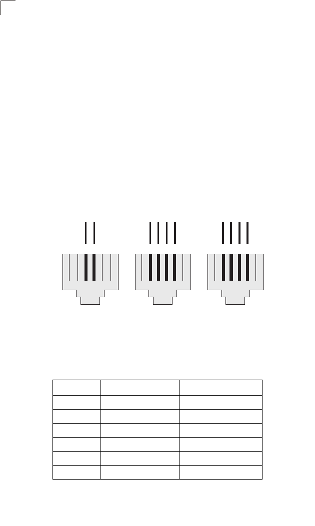
116
Cables
B
RJ-11 Ports
Standard telephone RJ-11 connectors and cabling can be found in several common
wiring patterns. These six-pin connectors can accommodate up to three wire-pairs
(three telephone lines), but usually only one or two pairs of conductor pins and wires
are implemented.
The RJ-11 ports on the side of the Gateway contain two wire-pairs, an inner pair
(pins 3 and 4) and outer pair (pins 2 and 5). On the LINE port, the inner wire-pair
carries both voice and digital data. On the PHONE port, the inner wire-pair carries
voice only.
The outer wire-pair is only connected if there is a second telephone line, and carries
voice only.
Figure B-4 RJ-11 Wiring
Table B-2 RJ-11 Port Pinouts
Pin Signal Name Wire Color
1 Not used
2 Line 2 Tip Black or White/Orange
3 Line 1 Ring Red or Blue/White
4 Line 1 Tip Green or White/Blue
5 Line 2 Ring Yellow or Orange/White
6 Not used
123456
Blue/White
White/Blue
R1 T1
123456
Red
Green
R1 T1 R2T2
Black
Yellow
123456
Blue/White
White/Blue
R1 T1 R2T2
White/Orange
Orange/White
6x2 Jack 6x4 Jack6x4 Jack
T = Tip R = Ring

117
Appendix C: Specifications
VDSL Functional Criteria
VDSL2 profile 30A (100 Mbps upstream / 100 Mbps downstream)
Band Plan: 8D, 12A, 12B and 17A
Signal Bandwidth: 25 kHz to 17.664 MHz
Multi-Carrier-Modulation (MCM) - DMT modulation
Interleaving: general convolution
Upstream Power Back-off (UPBO)
Remote firmware upgrade
Physical Characteristics
Ports
1 RJ-11 VDSL line (to phone jack in the wall)
1 RJ-11 phone line (POTS connection to telephone, with built-in splitter)
1 RJ-45 10/100BASE-TX (Ethernet connection to PC)
Ethernet Interface
4 RJ-45 connectors, auto MDI/X pinout detection
10BASE-T: 100-ohm, UTP cable; Category 3 or better
100BASE-TX: 100-ohm, UTP cable; Category 5 or better
*Maximum Cable Length - 100 m (328 ft)
VDSL2 Interface
RJ-11 connector, using standard phone cable (26 AWG)
Power Consumption
15 Watts maximum
Input Power
12 VDC (via AC power adapter), 1.25 A maximum
Size
20.95 x 16.05 x 3.62 cm (8.25 x 6.32 x 1.43 in.)
Weight
385 g (13.5 oz)

Specifications
118
C
Temperature
Operating: 0 °C to 40 °C (32 °F to 104 °F)
Storage: -25 °C to 70 °C (-13 °F to 158 °F)
Humidity
Operating: 20% to 90% (non-condensing)
LED Indicators
PWR, ALARM, VDSL LINK, VDSL TX/RX, LAN 1-4
Standards
Ethernet Standards
IEEE 802.3-2005 Ethernet Access
Ethernet, Fast Ethernet
Full-duplex flow control (ISO/IEC 8802-3)
IEEE 802.1D Spanning Tree Protocol
IEEE 802.1p priority tags
IEEE 802.3ac VLAN tagging
VDSL Standards
ANSI T1.424-2004 (T1E1 T1.424 - 2004)
ETSI TS 101 270-1 and TS 101 270-2
ITU-T G.992.2 (ADSL2+, ADSL2, ADSL)
ITU-T G.993.1-2004 - VDSL (including Annex F)
ITU-T G.993.2 - VDSL2
ITU-T G.993.2 Annex A - Band Plan for North America
ITU-T G.993.2 Annex K - Packet Transfer Mode-Transmission Convergence
ITU-T G.993.2 - Recommendation for Trellis Coding,
Impulse Noise Protection (INP), Upstream Power Backoff (UPBO),
Recommendation for latency path correction including scrambling,
Reed-Solomon forward error correction, and interleaving,
On-line Reconfiguration (OLR) Bit Swapping and Seamless Rate Adaptation
ITU-T G.993.2 Annex A - Power Spectral Density (PSD) Mask
ITU-T G.994.1 Handshake procedures for DSL transceivers
ITU-T 997 and 998 Band Plans
VDSL2 Profiles - Up to 17A
Rate Adaptation Mode - ITU G.993.2/G997.1 (Manual, Rate Adaptive AT INIT)
Other evolving ETSI, ANSI, ITU standards

Compliances
119
C
Compliances
Emissions
FCC Class B
FCC Part 68
IEC 61000-4-2 ESD (level 2)
CE
Environmental
RoHS compliant
Wireless Characteristics
Wireless Transmit Power (Maximum)
802.11b : 20.36 dBm
802.11g : 22.84 dBm
Wireless Receive Sensitivity (Maximum)
802.11b/g:
802.11b: -85 dBm @ 1 Mbps; -80 dBm @ 11 Mbps
802.11g: -83 dBm @ 6 Mbps; -66 dBm @ 54 Mbps
Operating Frequency
802.11g:
2.4 ~ 2.4835 GHz (US, Canada)
2.4 ~ 2.4835 GHz (ETSI, Japan)
802.11b:
2.4 ~ 2.4835 GHz (US, Canada)
2.4 ~ 2.4835 GHz (ETSI)
2.4 ~ 2.497 GHz (Japan)
Data Rate
802.11b: 1, 2, 5.5, 11 Mbps per channel
802.11g: 6, 9, 12, 18, 24, 36, 48, 54 Mbps per channel
Operating Channels
802.11g:
11 channels in base mode (US, Canada)
13 channels (ETSI, Japan)
802.11b:
11 channels in base mode (US, Canada)

Specifications
120
C
13 channels (ETSI)
14 channels (Japan)
Modulation Type
802.11g: CCK, BPSK, QPSK, OFDM
802.11b: CCK, BPSK, QPSK

121
Glossary
10BASE-T
IEEE 802.3 specification for 10 Mbps Ethernet over two pairs of Category 3, 4, or 5
UTP cable.
100BASE-TX
IEEE 802.3u specification for 100 Mbps Fast Ethernet over two pairs of Category 5
or better UTP cable.
Auto-Negotiation
Signalling method allowing each node to select its optimum operational mode (e.g.,
speed and duplex mode) based on the capabilities of the node to which it is
connected.
Bandwidth
The difference between the highest and lowest frequencies available for network
signals. Also synonymous with wire speed, the actual speed of the data
transmission along the cable.
Bridging
A device that connects two LANs, or two segments of the same LAN. Unlike routers,
bridges are protocol-independent. They simply forward packets without analyzing
and re-routing messages. Consequently, they’re faster than routers, but less
versatile.
Challenge-Handshake Authentication Protocol (CHAP)
A type of authentication in which the authentication agent (that is, the router) sends
the client a key to use to encrypt the user name and password. This enables the
user name and password to be transmitted in an encrypted form to protect them
against eavesdroppers.
Domain Name Service (DNS)
A system used for translating host names for network nodes into IP addresses.
Dynamic Host Control Protocol (DHCP)
Provides a framework for passing configuration information to hosts on a TCP/IP
network. DHCP is based on the Bootstrap Protocol (BOOTP), adding the capability
of automatic allocation of reusable network addresses and additional configuration
options.

Glossary
122
Dynamic Routing
Dynamic routing uses a routing protocol to exchange routing information with
neighboring routers on the network. It calculates routing tables based on a given
metric, such as lest number of hops or shortest path. It can respond to changes in
the status or traffic on the network, re-routing traffic as required.
End Station
A workstation, server, or other device that does not forward traffic.
Ethernet
A network communication system developed and standardized by DEC, Intel, and
Xerox, using baseband transmission, CSMA/CD access, logical bus topology, and
coaxial cable. The successor IEEE 802.3 standard provides for integration into the
OSI model and extends the physical layer and media with repeaters and
implementations that operate on fiber, thin coax and twisted-pair cable.
Fast Ethernet
A 100 Mbps network communication system based on Ethernet and the CSMA/CD
access method.
Firewall
A firewall is designed to prevent unauthorized access to or from a private network
Full Duplex
Transmission method that allows two network devices to transmit and receive
concurrently, effectively doubling the bandwidth of that link.
Hosting Server
A network device that may provide a limited number of services for external IP
clients, but is also used to transparently redirect specific service requests (such as
web or FTP) to other dedicated local servers.
Internet Group Management Protocol (IGMP)
A protocol through which hosts can register with their local router for multicast
services. If there is more than one multicast switch/router on a given subnetwork,
one of the devices is made the “querier” and assumes responsibility for keeping
track of group membership.
Internet Service Provider (ISP)
A company that provides access to the Internet. This may be your local telephone
company, or a dedicated Internet service company.

123
Glossary
ITU
International Telecommunication Union
ITU-T
Telecommunication Standardization Section of ITU
LAN Segment
Separate LAN or collision domain.
Layer 2
Data Link layer in the ISO 7-Layer Data Communications Protocol. This is related
directly to the hardware interface for network devices and passes on traffic based on
MAC addresses.
LED
Light emitting diode used for monitoring a device or network condition.
Local Area Network (LAN)
A group of interconnected computer and support devices.
Media Access Control (MAC)
A portion of the networking protocol that governs access to the transmission
medium, facilitating the exchange of data between network nodes.
Management Information Base (MIB)
An acronym for Management Information Base. It is a set of database objects that
contains information about a specific device.
Maximum Transfer Unit (MTU)
The maximum transfer unit for traffic crossing this device. MTU should be set to a
value that minimizes unnecessary fragmentation and maximizes the transfer of large
sequential data streams.
Media Dependent Interface (MDI)
The IEEE standard for the UTP interface to twisted-pair Ethernet. MDI defines a
straight-through pin assignment that allows you to connect the router to any
workstation or server that has a properly installed network adapter card using the
supplied crossover cable. Pin-out assignments are shown in Appendix B.
Media Dependent Interface - Crossed (MDI-X)
MDI-X port types cross the receive and transmit signals internally, and can be used
with straight-through cable to connect the router to a similar networking device (such
as a hub or switch). Note that if you use the supplied crossover cable to connect to a

Glossary
124
similar networking device, then you must connect to an MDI port on the other
device. Pin-out assignments are shown in Appendix B.
Network Address Translation (NAT)
A standard that enables a local-area network (LAN) to use one set of IP addresses
for external traffic and a second set of addresses for internal traffic.
Network Time Protocol (NTP)
NTP provides the mechanisms to synchronize time across the network. The time
servers operate in a hierarchical-master-slave configuration in order to synchronize
local clocks within the subnet and to national time standards via wire or radio.
Password Authentication Protocol (PAP)
A basic form of authentication, in which a user’s name and password are transmitted
over a network and compared to a table of name-password pairs.
Ping
A utility used to determine whether a specific IP address is accessible. It works by
sending a packet to the specified address and waiting for a reply.
Plain Old Telephone Service (POTS)
One of the services using voice band. Sometimes used as a descriptor for all voice
band services.
Point-to-Point Protocol (PPP)
A protocol for connecting remote hosts to the Internet using TCP/IP.
PPP over Ethernet (PPPoE)
A protocol for connecting remote hosts to the Internet over an always-on connection
by simulating a dial-up connection.
PSTN
Public Switched Telephone Network.
Private Branch Exchange (PBX)
A telephone exchange local to a particular organization who use, rather than
provide, telephone services.
Quality of Service (QoS)
A network protocol used to specify a guaranteed throughput level. This protocol is
often used by Internet service providers to guarantee their customers a minimum
end-to-end latency.

125
Glossary
Rate Adaptive
A VDSL service that automatically adjusts the transmission rate depending on line
quality and loading to ensure data quality (such as, keeping within a maximum error
rate).
Router
A device used to interconnect networks over local or wide areas and provide traffic
control and filtering functions.
Routing
Routing forwards incoming IP packets using statically defined routes or a dynamic
routing protocol such as RIP (or RIP 2).
Routing Information Protocol (RIP)
A protocol that specifies how routers exchange routing table information.
RJ-45 Connector
A connector for twisted-pair wiring.
Secure Shell (SSH)
A secure replacement for remote access functions, including Telnet. SSH can
authenticate users with a cryptographic key, and encrypt data connections between
management clients and the switch.
Session Initiation Protocol (SIP)
A control protocol used to create sessions with one or more participants for
applications including Internet telephony and multimedia conferences.
Splitter
A filter to separate VDSL signals from POTS signals to prevent mutual interference.
(Note that an external splitter is not required for this Gateway.)
Static Route
Static routes are manually configured entries in the routing table that indicate the
next hop (router) that must be used when sending data to a specific subnet or host.
Telnet
Defines a remote communication facility for interfacing to a terminal device over
TCP/IP.
Trivial File Transfer Protocol
A simple file transfer method that uses the User Datagram Protocol (UDP), and
therefore provides no error recovery.

Glossary
126
TIA
Telecommunications Industry Association
Transmission Control Protocol/Internet Protocol (TCP/IP)
Protocol suite that includes TCP as the primary transport protocol, and IP as the
network layer protocol.
Universal Plug-and-Play (UPnP)
A set of protocols that allows devices to connect seamlessly and simplifies the
deployment of home and office networks, using auto-discovery of other network
devices, acquiring information about device capabilities, and requests for services.
UTP
Unshielded twisted-pair cable.
User Datagram Protocol (UDP)
UDP provides a datagram mode for packet-switched communications. It uses IP as
the underlying transport mechanism to provide access to IP-like services. UDP
packets are delivered just like IP packets – connection-less datagrams that may be
discarded before reaching their targets. UDP is useful when TCP would be too
complex, too slow, or just unnecessary.
Very high data rate Digital Subscriber Line (VDSL)
A family of digital telecommunications protocols designed to allow high speed data
communication at data rates from below 1 Mbps to 52.8 Mbps with corresponding
maximum reach ranging from 4500 feet to 1000 feet using 24 gauge twisted pair
cable over the existing copper telephone lines between end-users and service
providers.
Very high data rate Digital Subscriber Line 2 (VDSL2)
VDSL2 as defined in ITU-T Recommendation G.993.2 is an enhancement to the first
VDSL standard (G.993.1). It supports transmission at a bi-directional net data rate
(the sum of upstream and downstream rates) of up to 200 Mbps on twisted pair
cables using a bandwidth of up to 30 MHz.
Virtual Private Network (VPN)
A secure tunnel used to protect data passing from one network to another over the
Internet.
Wide Area Network (WAN)
A computer network that spans a relatively large geographical area. Typically, a
WAN consists of two or more local-area networks (LANs).

127
Numerics
100BASE-TX 16
10BASE-T 16
10BASE-T/100BASE-TX pin
assignments 113
A
auto-configuration server 108
B
bridge mode, setting 36, 54
bridging 29
C
cable
crossover 115
straight-through 114
testing category 5 cable 115
cable connections 26
Class of Service, See CoS
compliances
emissions 119
environmental 119
configuration files, restoring
defaults 58
CoS
configuring traffic classification 106
queue mapping 106
crossover Ethernet cable 115
D
default IP address 35
default IP gateway, configuration 66
default priority, ingress port 106
default router 30
DHCP 65
client 32, 71
client configuration 71
displaying clients 53
dynamic configuration 65
Gateway as client 65
Differentiated Services, See DiffServ
DiffServ 105
DNS
general configuration 71
downloading software 58
dynamic DNS services 68
dynamic IP 37
setting WAN type 37
dynamic IP address assignment
WAN interface 65
dynamic routing 30, 74
E
Ethernet 16
event logging 53
F
factory default settings, restoring 58
filtering
IP addresses 91
firewall 33
firewall, configuration 90
firmware
displaying version 50
upgrading 58
front panel 17, 18, 19, 20, 21, 22, 23,
24
FTP server, See also local server
G
Gateway
description 13
features 15
H
hardware version, displaying 50
hardware, description 16
HTTPS 109
secure-site certificate 109
I
IGMP 102
proxy 102
snooping 102
Index

Index
128
snooping, setting fast leave 102
installation
connecting cables 26
powering on 27
IP address
default setting 35
DHCP 65
IP filter, for management access 57
ISP, single-user account 32
L
LED indicators 17
problems 111
local server
FTP 33
Web 33
log-in, Web interface 45
logon authentication 57
logs, displaying messages 53
M
main menu 47
management access, IP filter 57
management IP address, LAN 71
MINI-DIN port 16
MTU, configuring 39
multicast filtering 101
N
NAT 32
configuration 86
Network Address Translation, See NAT
network applications
accessing a remote site 30
accessing the Internet 31
network, examples 29
NTP
refresh time 56
server 56
O
operating mode, setting 36
P
package contents 25
packet filtering 91
password 57
administrator setting 57
pin assignments 113
10BASE-T/100BASE-TX 113
RJ-11 116
pinging network devices 58, 59
port
MINI-DIN 16
RJ-11 16
RJ-45 16
port indicators 17
port priority 106
default ingress 106
ports
autonegotiation 72
configuring 72
duplex mode 72
speed 72
powering on 27
PPPoE 37
service name 39
setting WAN type 39
WAN interface 67
priority, default port ingress 106
problems, troubleshooting 111
Q
QoS 104
Quality of Service, See QoS
R
rate limit, setting 104
rear panel 17, 18, 19, 20, 21, 22, 23, 24
restarting the system 58
RFC 1388 30
RIP 30, 31
selecting version 74
RIP 1 31
RIP 1, See also RIP
RIP 2 30, 31
RJ-11
pin assignments 116
port 16
RJ-45 port 16
router 31

Index
129
router mode, setting 36, 54
routing 30, 31
dynamic 30
static 30
table 31
Routing Information Protocol, See RIP
S
Secure Shell, See SSH
setup wizard 35
single-user account 32
software
displaying version 50
downloading 58
specifications
component 117
environmental 118
power 117
VDSL 117
SSH 60
standards
IEEE 118
ITU-T 118
static addresses, setting 91
static IP 37
setting WAN type 38
static IP address, WAN interface 66
static routing 30, 73
straight-through Ethernet cable 114
STUN server 109
system
indicators 17
requirements 25
system clock, setting 56
system information 50
system software, downloading from
host 58
T
TCP/IP, PC configuration 27
time, setting 56
troubleshooting 111
Internet connection 112
management access 112
troubleshooting, Gateway
indicators 111
U
upgrading software 58
V
VDSL 95
configuring 95
data rate, maximum 96
description 14
displaying communication
statistics 95
displaying performance statistics 98
displaying signal status 95
fast and interleaved channels 96
functional specifications 117
interleave delay, maximum 96
resetting a port 96
signal-to-noise margin 99
W
WAN connection, setting type 37
WAN interface
PPPoE 67
static IP address 66
WAN interface, dynamic IP address
assignment 65
Web interface
access requirements 45
home page 46
menu list 47
Web server, See also local server

Index
130

20 Mason • Irvine, CA 92618 • Phn: 949-679-8000 • www.smc.com
ECG9210-04
E022010-DT-R01
150200000095A