Accton Technology HIVEAP20AG HiveAP 20ag User Manual UserMan HEDHIVEAP20AG revised3
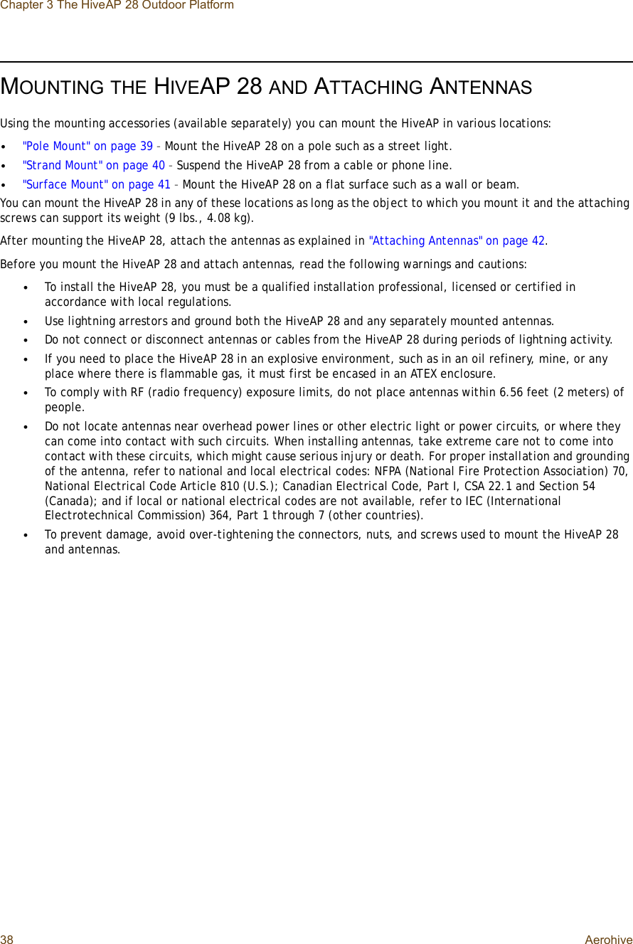
Accton Technology Corp HiveAP 20ag UserMan HEDHIVEAP20AG revised3
UserManual.wiki
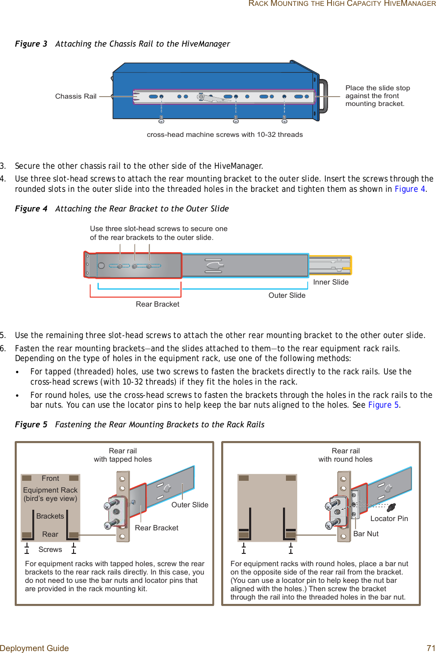
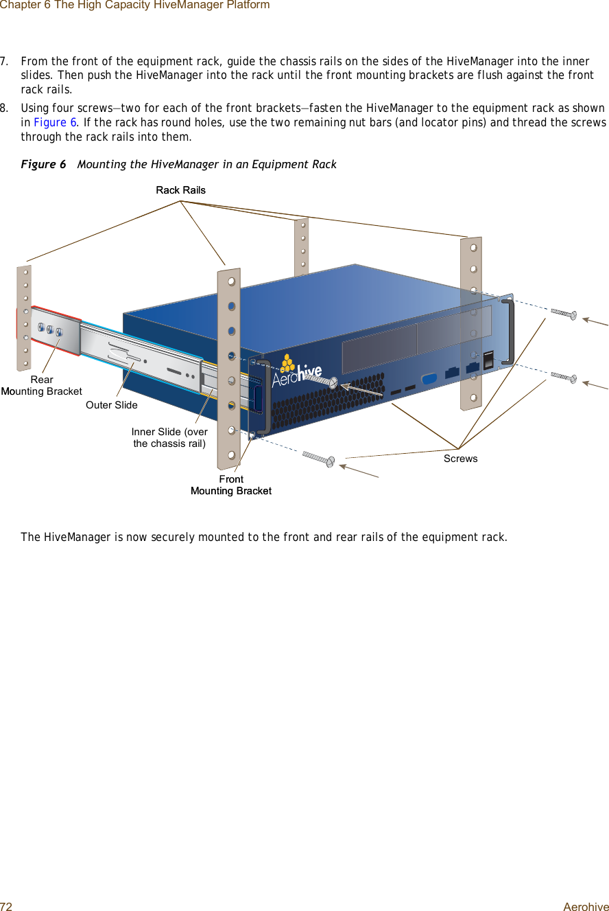
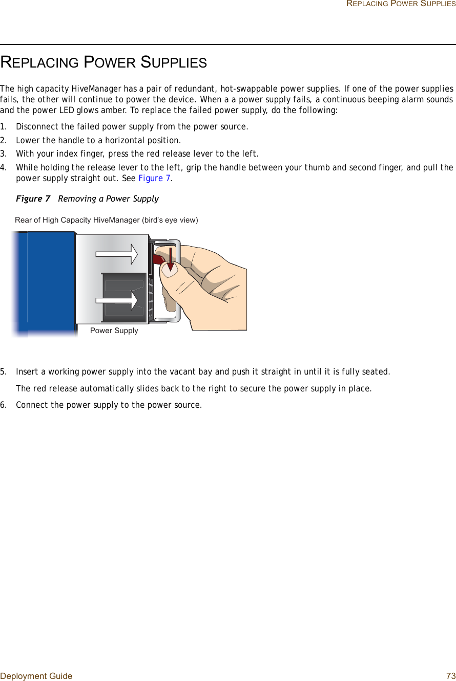
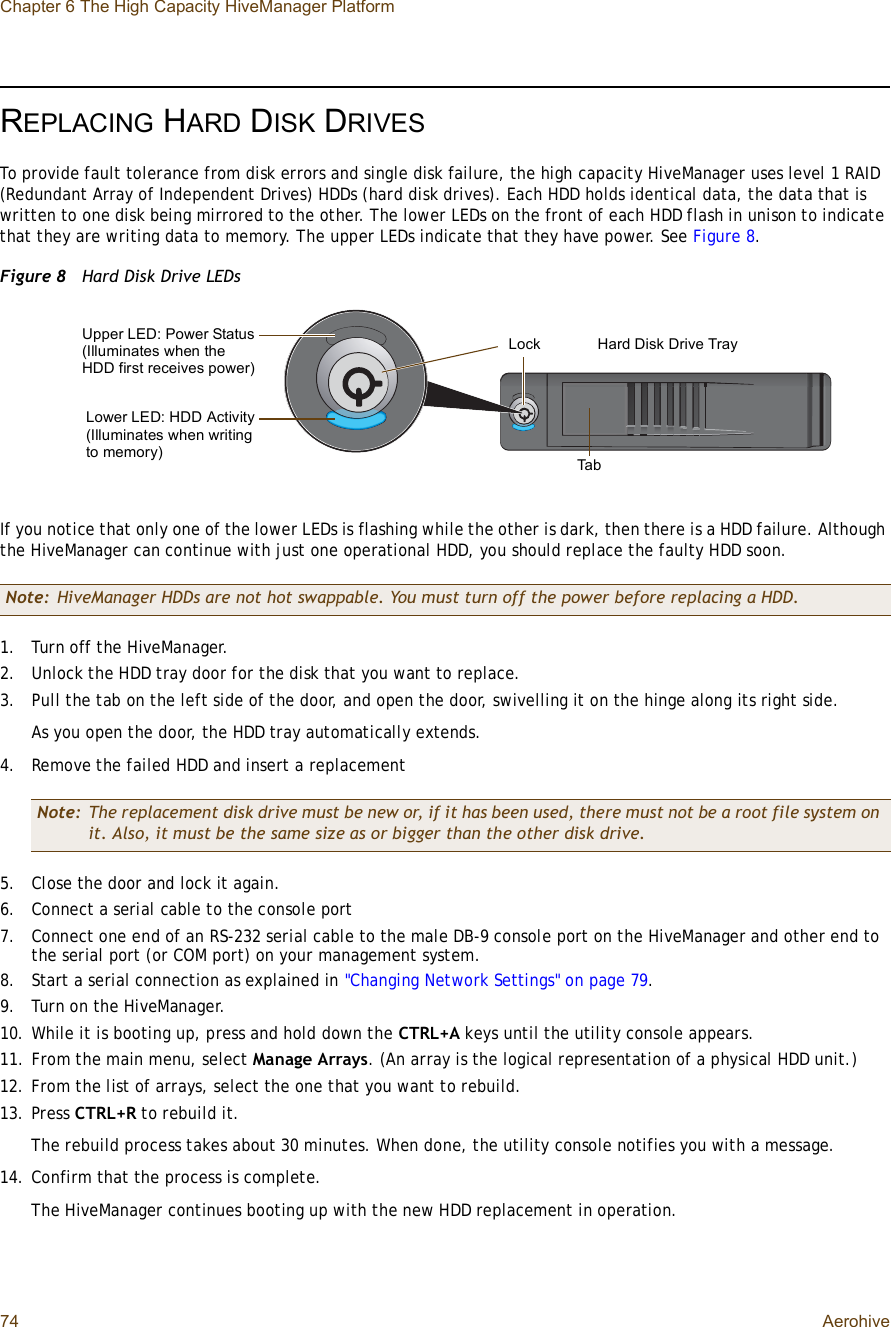
>
Accton Technology
>
HIVEAP20AG User Manual
>
User Manual 1
Contents
1.
User Manual 1
2.
User Manual 2
User Manual 1
Navigation menu
Upload a User Manual
Namespaces
Wiki Guide
HTML
PDF
Info
Views
User Manual
Discussion / Help
Navigation