Accton Technology HWS65051DW Zibgee 2.4GHz Wireless Door/Window Sensor User Manual SMCDW30 Z IG R02 20150415
Accton Technology Corp Zibgee 2.4GHz Wireless Door/Window Sensor SMCDW30 Z IG R02 20150415
User Manual
Copy right© 2015 SMC. All Rights Reserved
na.smc.com
Page 1I/M SMCDW30-D V2.0
1 Models
This guide covers the following model:
• SMCDW30-Z
2 Part Lists
The package contents include:
• Door-Window Sensor
• Mounting Bracket / Shim x 2
• Sensor Magnet
• Mounting Screws x 5
• CR2 Battery
• Wall Anchors x 5
• Double-Sided Tape x 2
• This Guide
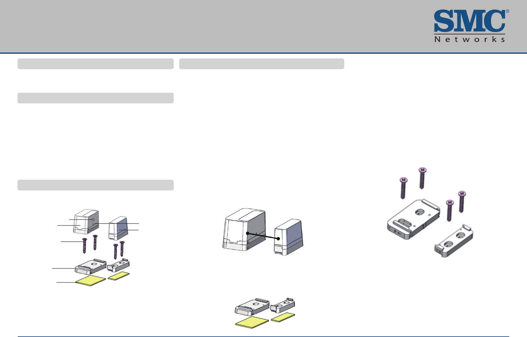
3 Key Components
4 Mounting
• Do not physically mount the sensor until it has been
paired with the system.
• Do not mount the sensor directly on or near metal
framing or other large metallic objects, which can weaken
transmitted radio signal.
• Place the sensor indoors and away from sources of
water / moisture and other extreme weather conditions.
• Always mount the sensor portion of the product to fixed
location of the door or window.
• Stacking spacers provided can be used to elevate the
magnet to be closer to the sensor.
Identify the installation locations on the door or window.
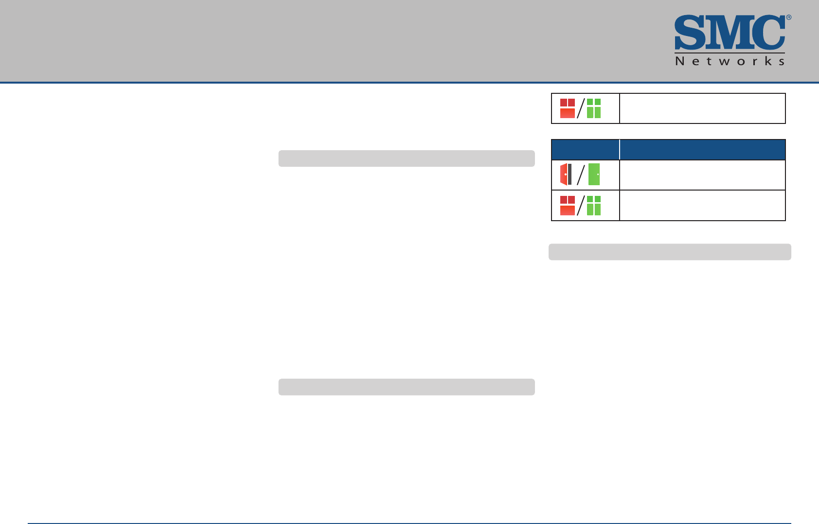
Step A. Orient the sensor and magnet so the alignment
arrows face each other when the door or window is
closed. The gap between the sensor and the magnet
should be greater than 1 inch and less than 1.5
inches.
Step B. Choose to mount with either double-sided tape or
screws:
Double-sided tape:
1. Clean the surface where the sensor will be mounted,
as dust and particles can reduce the adhesion of
double-sided mounting tape you will use to mount
the sensor.
2. Peel and attach the double-sided tape to the back
of the sensor mounting bracket / shim and magnet
bracket / shim.
3. Adhere to the wall, door, or window frame.
4. Slide the sensor and magnet into the bracket / shim.
Screws:
1. Use the supplied wall anchors and screw set to
secure the mounting bracket / shim to the wall, door
or window frame.
2. Slide sensor and magnet into the bracket / shim.
SMCDW30-Z Door Window Sensor
Aignment Arrow
Magnet
Low Voltage LED (RED)
Sensor
Screws Option
Mounting Bracket/
Shim
Double-sided Tape
Option
Copy right© 2015 SMC. All Rights Reserved
na.smc.com
Page 2I/M SMCDW30-D V2.0
1. Clean the surface where the sensor will be mounted,
as dust and particles can reduce the adhesion of
double-sided mounting tape you will use to mount
the sensor.
2. Peel and attach the double-sided tape to the back
of the sensor mounting bracket / shim and magnet
bracket / shim.
3. Adhere to the wall, door, or window frame.
4. Slide the sensor and magnet into the bracket / shim.
Screws:
1. Use the supplied wall anchors and screw set to
secure the mounting bracket / shim to the wall, door
or window frame.
2. Slide sensor and magnet into the bracket / shim.
Step C. Adding the Sensor to Touchscreen / Gateway.
1. At the Home screen, touch the Settings widget.
2. At the Keypad screen, touch the numbers to enter
your keypad code.
3. At the Settings menu, use the keypad to enter the
Installer Code (this code is the same for all Touch
screen / Gateway products installed by your
company).
4. At the Technician keyboard pad, enter your
Technician ID and touch Done.
5. At the Technician Settings menu, select Sensors &
Zones > Add a Sensor / Zone.
6. At the Add a sensor screen, use the arrow buttons
to select the number of sensors you want to add.
7. Click Next. The Locating Sensors screen appears
and the system scans the premises for wireless
sensors that can be added. These sensors must be
defaulted and not currently paired with another
Touchscreen / Gateway device.
8. Follow the system prompts to complete the add
process.
If no available sensors are found or fewer are found
than expected:
1. Touch Cancel Sensor / Zone Add to return to the
Technician Settings menu.
2. Touch Back to return to the Add a Sensor screen.
3. Check the signal strength between the sensor and
Touchscreen / Gateway (see “Test Signal Strength.)
4. If you encounter a problem, see “Troubleshooting.”
5 Testing Signal Strength
After adding the sensor to the Touchscreen / Gateway, test
the signal strength between the Touchscreen / Gateway and
its added sensors / security zones:
1. Perform steps 1 through 4 under “Adding the Sensor to
Touchscreen / Gateway.”
2. At the Technician Settings menu, select Sensors &
Zones > Sensor Diagnostics.
3. When the installed sensors / security zones appear,
touch the zone you want to test for connectivity and
follow the instructions from the Touchsreen / Gateway.
The Sensor Diagnostic for <Security Zone name>
appears as the system detects the current signal strength
between the selected sensor and the Touchsreen /
Gateway.
6 Viewing Event History
1. Touch the Security widget on the Home screen.
2. At the Dashboard, touch the History tab. The Zone
Event History shows the event history
7 Disabling Zones
The Touchsreen / Gateway system can bypass a zone,
so the zone is not monitored when the system is armed.
This is useful when a sensor is being repaired. You can
only change the Bypass state of a zone when the
system is disarmed. The system continues to log the
activity of bypassed zones in the Event History (see
“Viewing Event History.”).
1. With the system disarmed, touch the Security icon
on the Home screen.
2. At the Dashboard screen, touch the Bypass button
for the zone to be bypassed. The Bypass button of
the zone shows it is bypassed.
If the system is disarmed, the Security Status header
notes that some zones are bypassed.
SMCDW30-Z Door Window Sensor
Open/Closed window
Open/Closed doorway
Icons Meaning
Open/Closed window
Copy right© 2015 SMC. All Rights Reserved
na.smc.com
Page 3I/M SMCDW30-D V2.0
7 Disabling Zones
The Touchsreen / Gateway system can bypass a zone,
so the zone is not monitored when the system is armed.
This is useful when a sensor is being repaired. You can
only change the Bypass state of a zone when the
system is disarmed. The system continues to log the
activity of bypassed zones in the Event History (see
“Viewing Event History.”).
1. With the system disarmed, touch the Security icon
on the Home screen.
2. At the Dashboard screen, touch the Bypass button
for the zone to be bypassed. The Bypass button of
the zone shows it is bypassed.
If the system is disarmed, the Security Status header
notes that some zones are bypassed.
8 Deleting a Sensor
Deleting a sensor from the premises removes it from
being monitored by the customer’s Touchsreen /
Gateway system. This is not the same as disabling
(bypassing) a sensor. Delete a sensor only if it is being
de-installed from the Touchsreen / Gateway premises or
to reset it to factory default settings by deleting the
sensor and re-adding it immediately.
To delete a sensor from the Touchsreen / Gateway
system:
1. Perform steps 1 through 4 under “Adding the Sensor
to Touchsreen / Gateway .”
2. At the Technician Settings menu, select Sensors &
Zones > Delete a Sensor / Zone.
3. At the Premise Passphrase keyboard, retrieve the
Premise Passphrase for the current Touchsreen /
Gateway (the Premise Passphrase is unique to the
current Touchsreen / Gateway and was generated
upon Activation):
• Login to the Management Portal via the Internet.
• At the Dashboard, use the Start a Customer
Search tool to search for the current customer’s
account.
• When the Customer Search Results screen
appears, find the customer in the listed query
results and click the customer’s Account
Number. The Account Details of the current
customer appears.
4. Find the section Touchsreen / Gateway Premise
Pass Phrase.
5. At the Premise Passphrase for the current
Touchsreen / Gateway, enter Premise Passphrase
and click Done. The currently installed sensors /
security zones appear.
6. Touch the zone you want to delete, and then follow the
instructions provided by the Touchsreen / Gateway to
delete the sensor and security zone from the current
Touchsreen / Gateway system.
9 Factory Reset
1. When the sensor is removed from its packaging for the
first time, it is in factory reset / default mode. When you
install the battery, the sensor searches for a Touchsreen /
Gateway which it can pair.
2. To reset a sensor that has already been added to a
Touchsreen / Gateway and place it in Search mode,
delete it from the Touchsreen / Gateway.
3. To force the sensor into factory reset / default mode:
• Find the locking mechanism on the bottom of the
sensor. Push down on the back plate of the sensor
and slide it out.
• Remove the battery.
• While pressing and holding the tamper switch, insert
the battery into the sensor, with the positive (+) end,
matching the product marking.
• The pairing LED should flash.
• Release the tamper switch once the pairing LED
flashes. The sensor is now defaulted. If you are not
pairing to the system, remove the battery.
• Replace the sensor back plate.
SMCDW30-Z Door Window Sensor
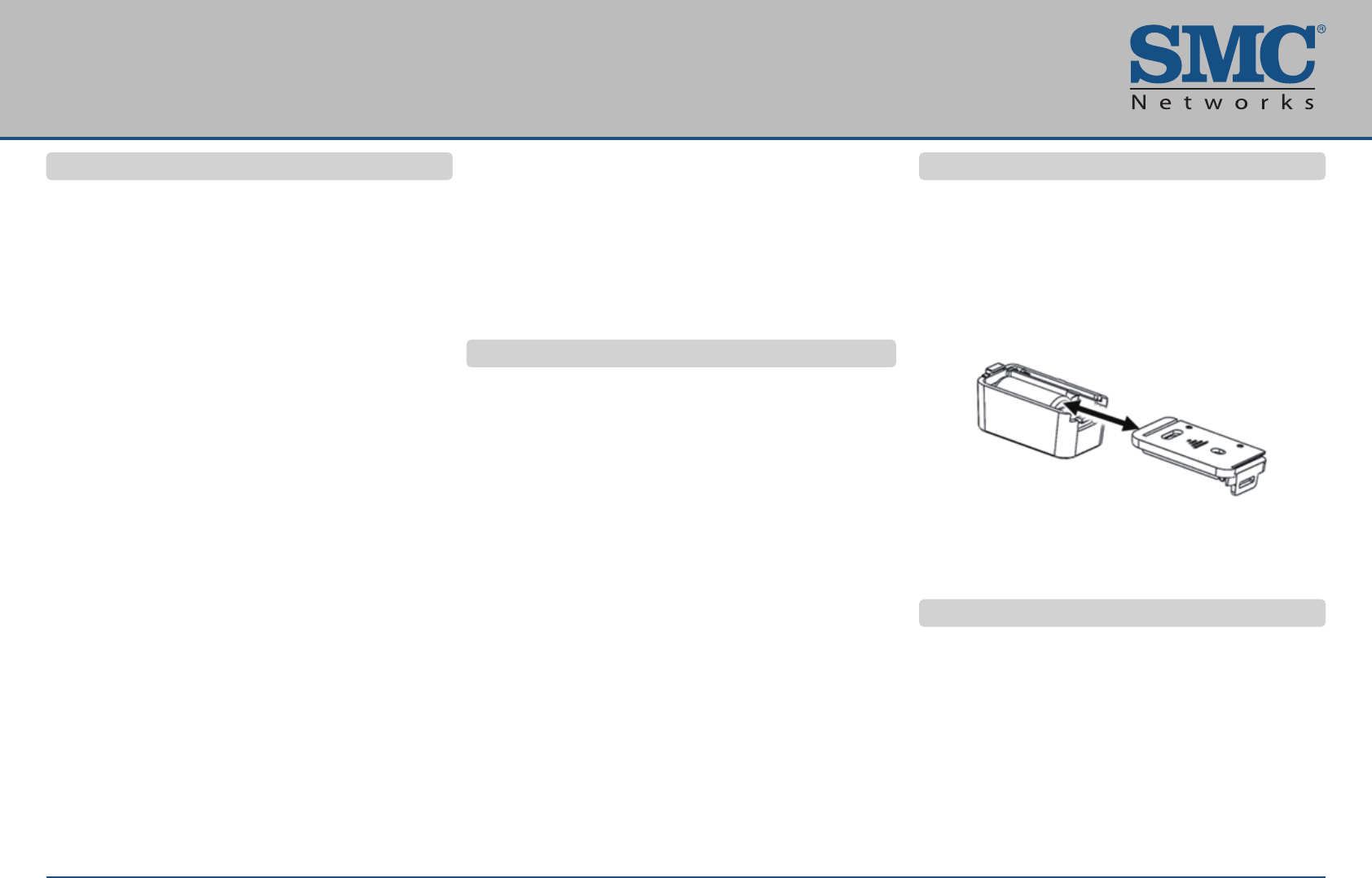
10 Battery Installation
A new sensor comes with a preinstalled battery
(CR2 Lithium Battery, DC 3V) with a quick-pull tab for
easy activation.
1. Find the locking mechanism on the bottom of the
sensor.
2. Push down on the back plate of the sensor and slide
out the plate.
3. Insert the CR2 battery into the sensor, with the
positive (+) end matching the product marking.
4. Replace the sensor back plate.
11 Troubleshooting
If you encounter a problem with the sensor:
• Be sure the product has been installed according to
the recommended guidelines found in this guide.
• If pairing to the system, confirm that the sensor has
been first defaulted, and then confirm that the
device is paired to system.
• Verify that a new battery has been installed properly
(see “Battery Installation”).
• Confirm the low voltage indicator is not lit on the
side sensor.
Copy right© 2015 SMC. All Rights Reserved
na.smc.com
Page 4I/M SMCDW30-D V2.0
5000954
This device complies with Industry Canada licence-exempt
RSS standard(s). Operation is subject to the following two
conditions: (1) this device may not cause interference, and
(2) this device must accept any interference, including
interference that may cause undesired operation of the
device.
Le présent appareil est conforme aux CNR d'Industrie
Canada applicables aux appareils radio exempts de licence.
L'exploitation est autorisée aux deux conditions suivantes:
(1) l'appareil ne doit pas produire de brouillage, et (2)
l'appareil doit accepter tout brouillage radioélectrique subi,
même si le brouillage est susceptible d'en compromettre le
fonctionnement.
"CAUTION:
1. To comply with FCC RF exposure compliance
requirements, a separation distance of at least 20 cm must
be maintained between the antenna of this device and all
persons.
2. This Transmitter must not be co-located or operating in
conjunction with any other antenna or transmitter "
NOTE: This equipment has been tested and found to comply
with the limits for a Class B digital device, pursuant to Part
15 of the FCC Rules. These limits are designed to provide
reasonable protection against harmful interference in a
residential installation. This equipment generates, uses and
can radiate radio frequency energy and, if not installed and
used in accordance with the instructions, may cause harmful
interference to radio communications.
SMCDW30-Z Door Window Sensor
150200001129A R02
10 Battery Installation
A new sensor comes with a preinstalled battery
(CR2 Lithium Battery, DC 3V) with a quick-pull tab for
easy activation.
1. Find the locking mechanism on the bottom of the
sensor.
2. Push down on the back plate of the sensor and slide
out the plate.
3. Insert the CR2 battery into the sensor, with the
positive (+) end matching the product marking.
4. Replace the sensor back plate.
11 Troubleshooting
If you encounter a problem with the sensor:
• Be sure the product has been installed according to
the recommended guidelines found in this guide.
• If pairing to the system, confirm that the sensor has
been first defaulted, and then confirm that the
device is paired to system.
• Verify that a new battery has been installed properly
(see “Battery Installation”).
• Confirm the low voltage indicator is not lit on the
side sensor.
12 ETL Logo and Standard Information
CONFORMS TO ANSI / UL STD. 634 and 60950-1
CERTIFIED TO ULC SUBJECT C634 and CAN / CSA
STD. C22.2 No. 60950-1
13 Compliances
FCC ID: HED-HWS65051DW
IC: 3857A-HWS65051DW
Warning: Changes or modifications to this unit not
expressly approved by the party responsible for
compliance could void the user authority to operate the
equipment.
“This device complies with Part 15 of the FCC Rules.
Operation is subject to the following two conditions:
(1) this device may not cause harmful interference, and
(2) this device must accept any interference received,
including interference that may cause undesired
operation.”
However, there is no guarantee that interference will not
occur in a particular installation. If this equipment does
cause harmful interference to radio or television
reception, which can be determined by turning the
equipment off and on, the user is encouraged to try to
correct the interference by one or more of the following
measures:
• Reorient or relocate the receiving antenna.
• Increase the separation between the equipment and
receiver.
• Connect the equipment into an outlet on a circuit
different from that to which the receiver is needed.
• Consult the dealer or an experienced radio/TV
technician for help.
14 Contact
SMC Networks - North America
20 Mason
Irvine, CA 92618
1-800-SMC-4YOU
24/7 Technical Support
With over 40 years of experience, SMC Networks is a
leading equipment provider in gateway and home
security customer premises equipment for Service
Providers in North America and internationally.
Visit us at: na.smc.com