Accton Technology IRAC750 Cloud-Enabled Enterprise Access Point User Manual Spark QSG 20160127
Accton Technology Corp Cloud-Enabled Enterprise Access Point Spark QSG 20160127
User Manual.pdf
Quick Star t Guide
Cloud-Enabled Enterprise Access Point
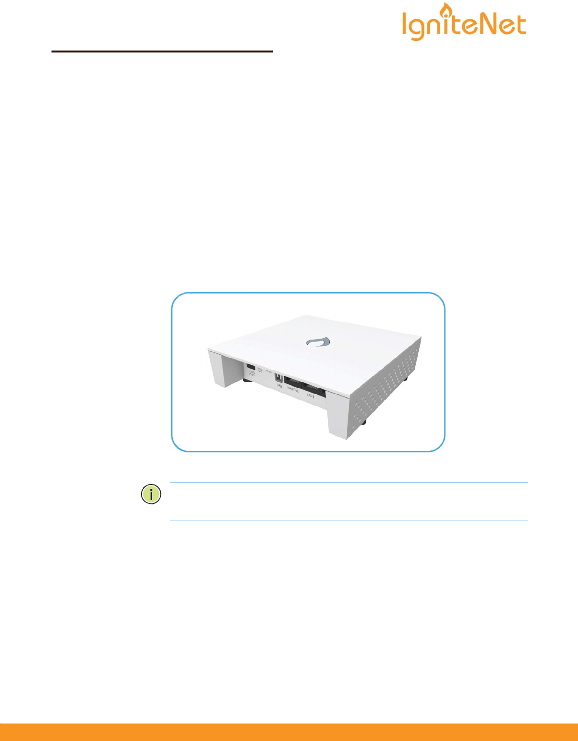
The Spark AC750 are dual AP. The units are designed to be operated either placed
on a desk or
mounted on a wall or ceiling. The package includes a mounting plate
for attaching
the AP to a wall or ceiling T-bar. The APs can be powered either by the
universal
power supply included in the package, through an Ethernet cable
connection from
a Power-over-Ethernet (PoE) injector, or from a 802.3af-compliant
PoE switch.
The Cloud-Enabled Enterprise Access Point includes these models:
IR-AC750 & IR-AC750-EU — dual-band concurrent enterprise AP with
integrated antennas
plus passive Power-over-Ethernet (PoE)
Note: For Safety and Regulatory information, refer to the Safety and Regulatory
Information document included with the AP.
www.ignitenet.com
– 1 –
Quick
Start
Guide
–
2
–
Follow the steps in this guide to install the AP in your network.
Caution: The planning and installation of the AP requires professional personnel
that are trained in the installation of radio transmitting equipment. The user is
responsible for compliance with local regulations concerning items such as
antenna
power for instance. Therefore, it is recommended to consult a professional
contractor knowledgeable in local radio regulations prior to equipment
installation.
1. Unpack the AP
Unpack the AP and check the package contents.
Cloud-Enabled Enterprise Access Point Spark
AC750
Mounting plate
Mounting kit — 4 screws, 4 wall plugs, and 4 rubber feet
Universal AC/DC power adapter
Documentation —Quick Start Guide and Regulatory and Safety Information
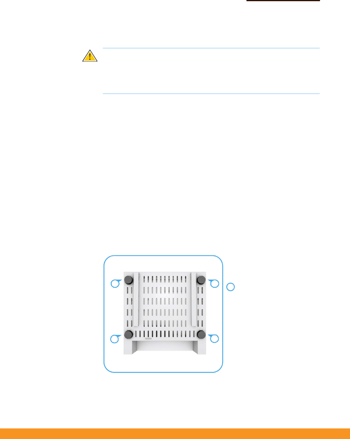
2. Mount the AP Using the AP on a desktop
If the AP is not mounted on a wall or on the ceiling, place the provided rubber feet
on the AP.
Desktop Mounting
1
1
Place the provided rubber feet over
1 the four screw holes.
1 1
Quick
Start
Guide
–
3
–
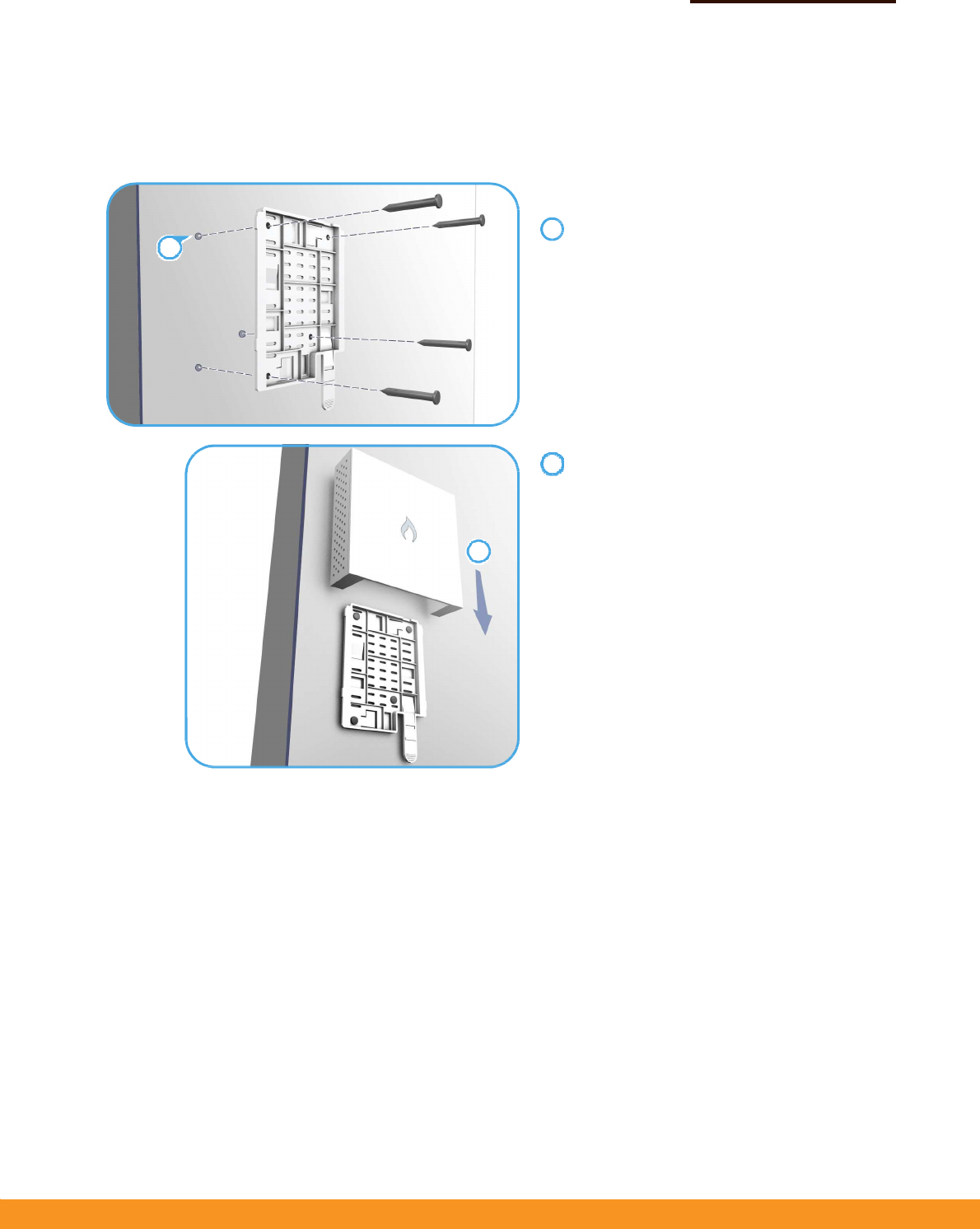
Mounting the AP on a wall
Mount the unit on a wall using the mounting plate, screws, and wall plugs provided
in the mounting kit.
Wall Mounting
At the installation location, hold the mounting
plate against the wall with its release tab pointing
down.
Mark the four holes for the wall plugs and screws.
Drill four holes for the wall plugs, and then insert
the plugs and tap them flush with the wall surface.
Align the mounting plate with the four holes, and
then use the four screws to secure it to the wall.
With its ports facing down, place the AP against
the wall above the mounting plate.
Slide the rails on the back of the AP down onto the
mounting plate until it snaps into its secured
position. Do not let go of the AP until you confirm
that it is secure.
2
1
1
2
Quick
Start
Guide
–
4
–
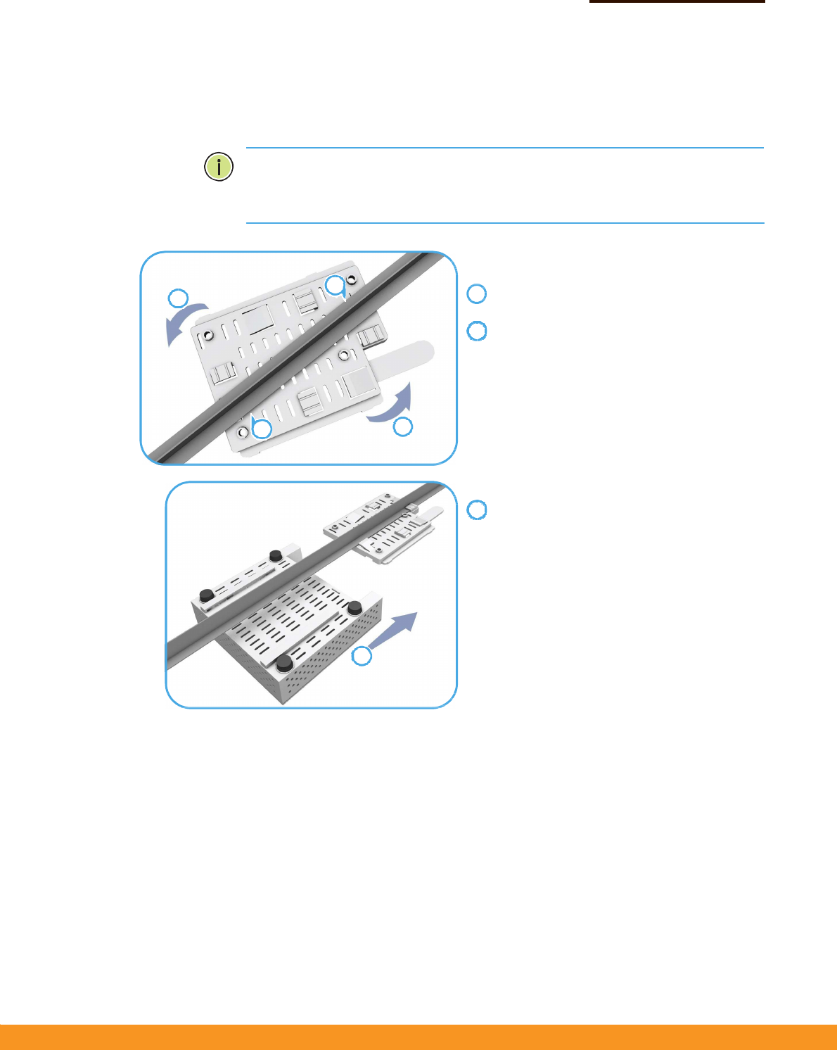
Mounting the AP on the ceiling
If the room is equipped with a suspended ceiling, use the mounting plate provided
in
the package to attach the AP to the metal ceiling T-bars.
The mounting plate supports two different sizes of suspended ceiling T-bars. The
position illustrated below is for 15 mm bars. Use the position at a 90 degrees angle
for 24.5 mm bars.
Suspended Ceiling Mounting
Press the retention clips of the mounting plate
against the ceiling T-bar.
Rotate the plate until the T-bar snaps into place.
Slide the rails on the back of the AP along the
sides of the ceiling mounting plate until it snaps
into its secured position.
3
1
2
1
2
1
2
3
Quick
Start
Guide
–
5
–
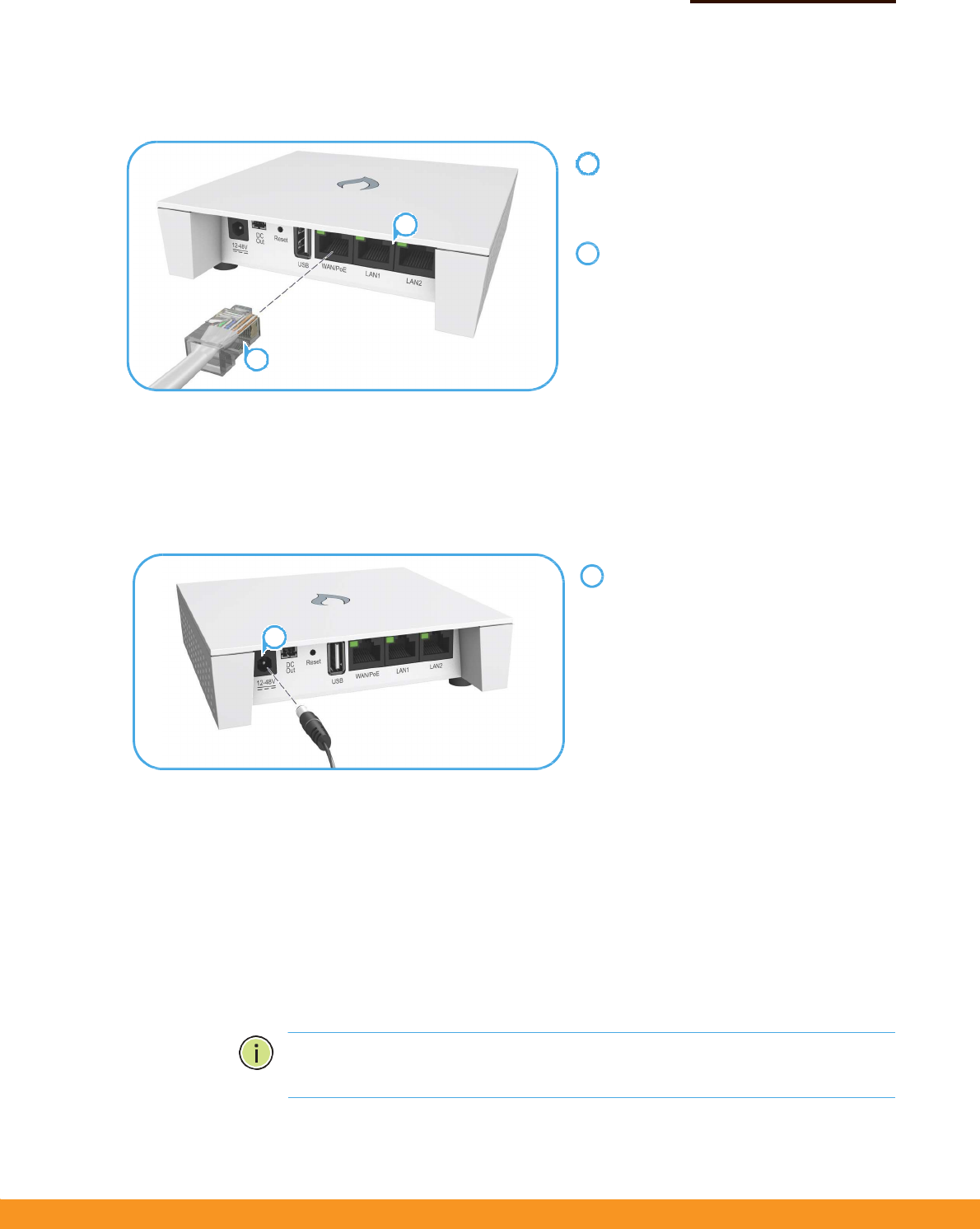
3. Connect Cables
Connect Ethernet cable to the 1000BASE-T (WAN/PoE) port on the unit.
Connect Category 5e or better cable to the
WAN/PoE RJ-45 port.
Connect the other end of this cable to a
PoE injector or LAN PoE switch (depending
on AP model).
(Optional) Connect local LAN devices to
any of the other RJ-45 ports on the AP
using Category 5 or better cable.
These 100BASE-TX ports are labeled LAN1
and LAN2.
4. Connect Power
The AP can be powered either by the AC/DC power adapter provided in the
package,
by a PoE power injector (Spark AC750)
Powering the AP with the AC/DC Power Adapter
Connect the cable from the power adapter
to the DC power jack on the AP.
Connect the power adapter to a nearby AC
power source (100-240 VAC, 50/60 Hz).
Powering the AP with a PoE Injector or PoE Switch
Connect Ethernet cable from the WAN/PoE port of the AP to a port on the PoE
power source device:
Spark AC750 — a PoE power injector (passive PoE, 24-48 VDC).
switch.
Make sure that the PoE power injector or switch is connected to the
LAN.
Note: Connecting the Ethernet cable from the AP to a PoE injector or PoE switch
powers on the unit.
2
1
1
2
1
1
Quick
Start
Guide
–
6
–
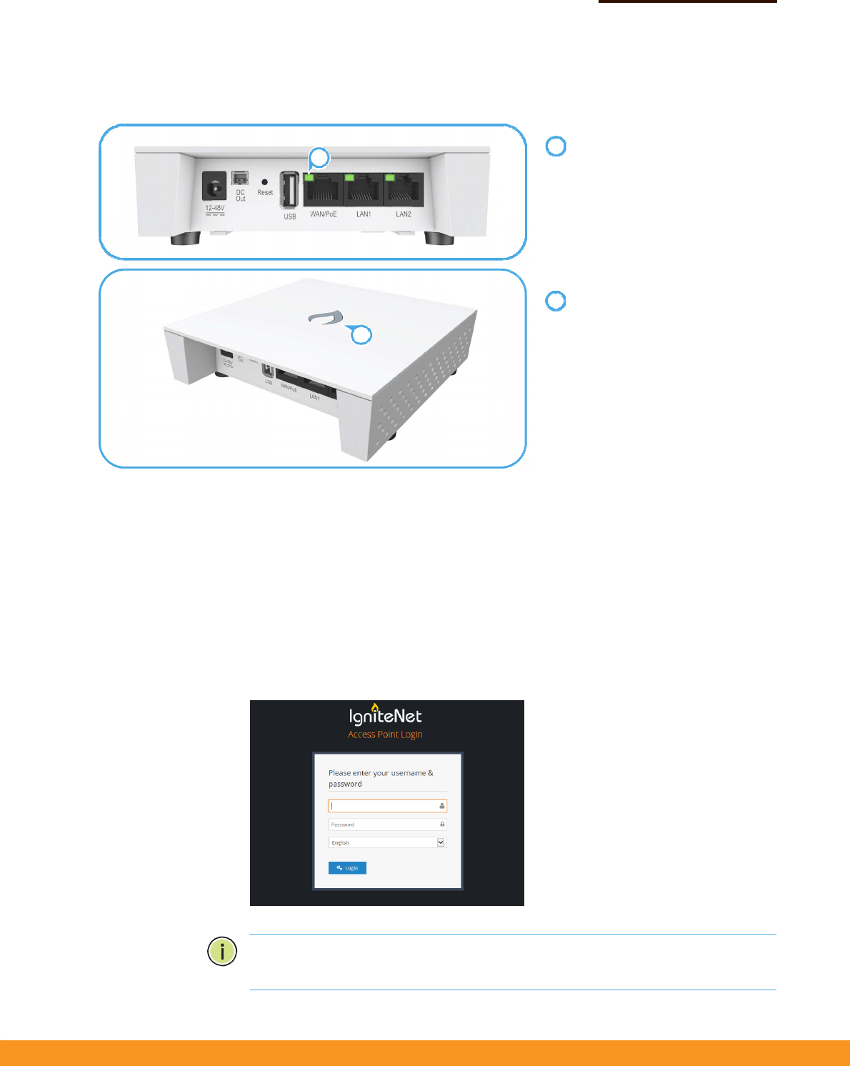
5. Verify AP Operation
Verify basic AP operation by checking the system LEDs.
The WAN/PoE port link/activity LED
should be on/blinking green.
When connected, the LAN1 and
LAN2 port link/activity LEDs
should also be on/blinking green.
The system/wireless LED should be
on red when the AP is powered on,
or on/blinking green (2.4 GHz) or
blue (5 GHz).
6. Connect to the Web
User Interface
When managed in a stand-alone mode, the AP offers a web-based management
interface for the configuration of all the unit’s features. If cloud-managing the AP,
go directly to “Manage the AP with the IgniteNet Cloud Controller” on page 7.
To access the web interface, connect a PC directly to the AP’s LAN1 or LAN2 RJ-45
port. You must first set your PC IP address to be on the same subnet as the AP (that
is, the PC and AP addresses must both start 192.168.2.x with a subnet mask of
255.255.255.0). In a web browser, enter the AP’s default management IP address of
192.168.2.1 to access the web login page.
Log in to the web interface using
the
default settings:
Login Name — root
Password — admin123
Note: To reset the AP to factory default settings, press and hold down the AP’s
Reset button for 5 seconds.
1
2
1
2
Quick
Start
Guide
–
7
–
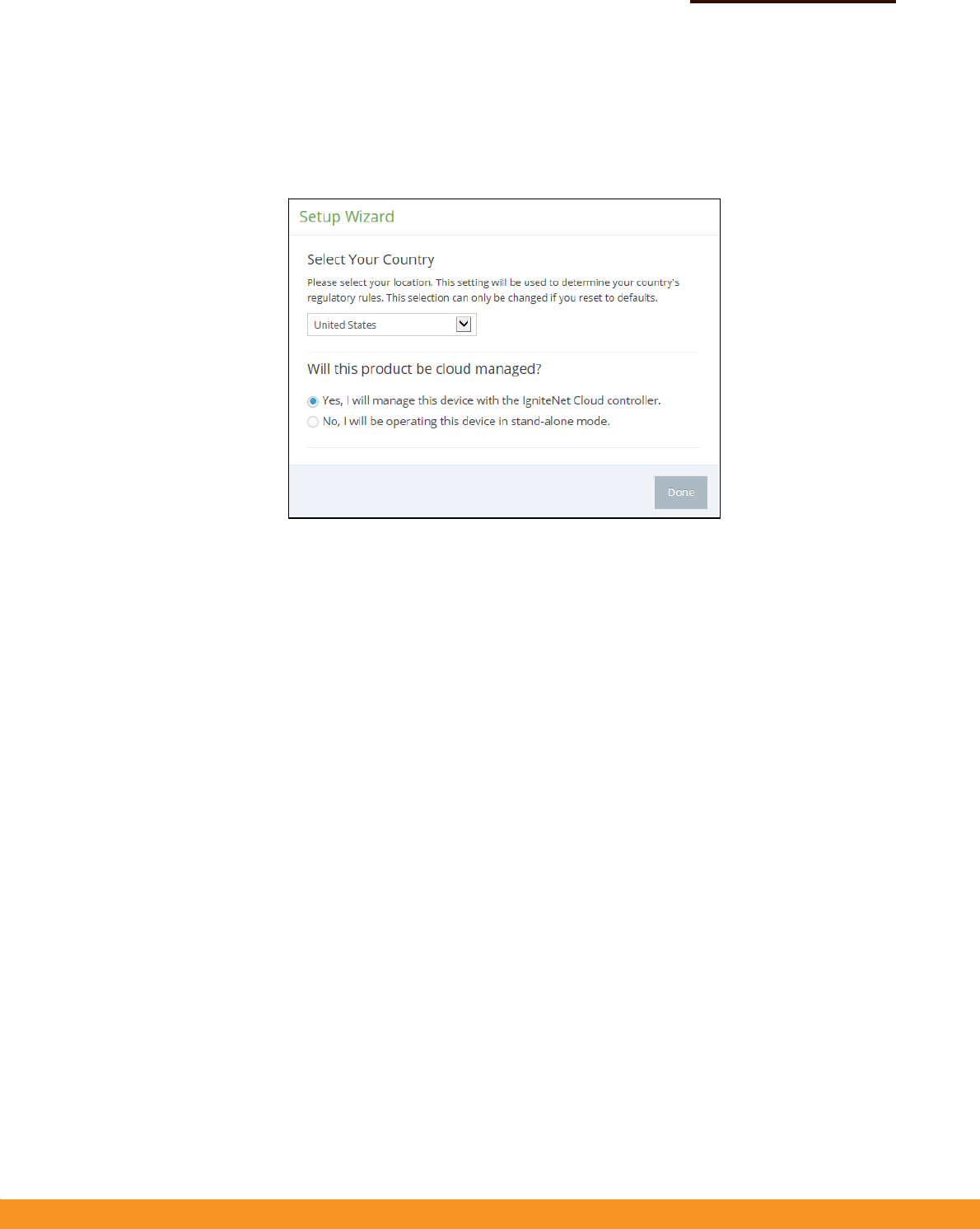
7. Complete the Setup
Wizard
The first time you log in to the web interface, the Setup Wizard is displayed.
Select the country of operation for the AP. Setting the correct country ensures that
the radios operate within local regulations specified for Wi-Fi networks.
Manage the AP with the IgniteNet Cloud Controller
Go to cloud.ignitenet.com to register your AP.
Log in and select Devices from the menu. Click Add Device and enter the AP serial
number and MAC address to register the AP with your cloud network. The serial
number and MAC address can be found on the product packaging or label.
Manage the AP in Stand-Alone Mode
If you select to manage the AP in stand-alone mode, complete the “Easy” or
“Advanced” setup in the wizard.
For more information on AP configuration in stand-alone mode, refer to the User
Guide.

Quick
Start
Guide
Hardware Specifications
Chassis
Size (L x W x H:) 121 x 121 x 30.5 mm (4.76 x 4.76 x 1.2 inches)
Weight 196 g (0.43 lb)
Temperature
Operating: -20 °C to 65 °C
Humidity Operating: 10% to 90% (non-condensing)
Network Interfaces
Ports WAN/PoE RJ-45 Port: 1000BASE-T, passive PoE
LAN1 RJ-45 Port: 100BASE-TX
LAN2 RJ-45 Port: 100BASE-TX
2.4 GHz Radio IEEE 802.11b/g/n
5 GHz Radio IEEE 802.11a/n/ac
Radio Frequencies 2412 ~ 2462 MHz
5180 ~ 5240 MHz
5745 ~ 5825 MHz
Power Supply
AC Power Adapter Input: 100-240 VAC, 50-60 Hz, auto-sensing
Output: 12, 24 VDC, 1.5 A maximum @ 12 VDC
Passive PoE Input Power 24 VDC, 0.7 A maximum @ 24 VDC
Regulatory Compliances
Radio EN 300 328 V1.8.1:2012
EN 301 893 V1.7.1:2012
EN 301 489-1 V1.9.2 (2011-09)
EN 301 489-7 V1.3.1:2005
FCC Part 15C 15.247/15.207
FCC Part 15E 15.407
Emissions EN 55022 2010+AC:2011
EN 61000-3-2 2006+A1:2009+A2:2009
FCC Class B Part 15
Immunity EN 55024 : 2010
EN 61000-4-2 : 2009
– 8 –
Spark AC750
E052015-CS 150200001184A R01
Item Specification

Quick
Start
Guide
Federal Communication Commission Interference
Statement
This device complies with Part 15 of the FCC Rules. Operation
is subject to the following two conditions: (1) This device may
not cause harmful interference, and (2) this device must
accept any interference received, including interference that
may cause undesired operation.
This equipment has been tested and found to comply with the
limits for a Class B digital device, pursuant to Part 15 of the
FCC Rules. These limits are designed to provide reasonable
protection against harmful interference in a residential
installation. This equipment generates, uses and can radiate
radio frequency energy and, if not installed and used in
accordance with the instructions, may cause harmful
interference to radio communications. However, there is no
guarantee that interference will not occur in a particular
installation. If this equipment does cause harmful interference
to radio or television reception, which can be determined by
turning the equipment off and on, the user is encouraged to
try to correct the interference by one of the following
measures:
- Reorient or relocate the receiving antenna.
- Increase the separation between the equipment and
receiver.
- Connect the equipment into an outlet on a circuit
different from that
to which the receiver is connected.
- Consult the dealer or an experienced radio/TV
technician for help.
FCC Caution: Any changes or modifications not expressly
approved by the party responsible for compliance could void
the user's authority to operate this equipment.
This transmitter must not be co-located or operating in
conjunction with any other antenna or transmitter.

Quick
Start
Guide
Radiation Exposure Statement:
This equipment complies with FCC radiation exposure limits
set forth for an uncontrolled environment. This equipment
should be installed and operated with minimum distance 20cm
between the radiator & your body.
Note: The country code selection is for non-US model only and
is not available to all US model. Per FCC regulation, all WiFi
product marketed in US must fixed to US operation channels
only.
Professional installation instruction
1. Installation personal
This product is designed for specific application and needs to
be installed by a qualified personal who has RF and related
rule knowledge. The general user shall not attempt to install or
change the setting.
2. Installation location
The product shall be installed at a location where the radiating
antenna can be kept 20cm from nearby person in normal
operation condition to meet regulatory RF exposure
requirement.
3. External antenna
Use only the antennas which have been approved by the
applicant. The non-approved antenna(s) may produce
unwanted spurious or excessive RF transmitting power which
may lead to the violation of FCC limit and is prohibited.
4. Installation procedure
Please refer to user’s manual for the detail.
5. Warning
Please carefully select the installation position and make sure
that the final output power does not exceed the limit set force
in relevant rules. The violation of the rule could lead to serious
federal penalty.