Accton Technology ML60MDSB Metrolinq 60 GHz Module User Manual 60G okx
Accton Technology Corp Metrolinq 60 GHz Module 60G okx
Contents
- 1. Users Manual
- 2. User Manual
Users Manual
Brandname:IgniteNet
60GHz Module
Model name: RDO-60-FB-USBB-8
User’s Manual
TableofContents
1.Introduction.....................................................................................................................3
1.1 Overview......................................................................................................................................................3
1.2 DefinitionsandAcronyms............................................................................................................................3
1.3 Background..................................................................................................................................................3
2.FunctionalDescription......................................................................................................4
2.1 EnableTestModeonWindowsHostPC......................................................................................................4
2.1.1 DisableDriverSigning..............................................................................................................................4
2.1.2 AddingTestCertificate............................................................................................................................5
2.2 InstallingtheHostandNetworkdriver........................................................................................................6
2.2.1 InstallingdriveronWindows7................................................................................................................6
2.3 Loadingimageontoboards..........................................................................................................................7
2.3.1 Loadingimageontodevicefortheveryfirsttime...................................................................................7
2.3.2 Loadingimageontodevicethatalreadyhaveapriorimage...................................................................7
2.4 CreatingaNetworkwithtwoPRS4601s.......................................................................................................7
2.4.1 ConfiguringPCP/STAModes....................................................................................................................7
2.4.2 Creatinganetworkprofile.......................................................................................................................8
2.4.3 Startingandconnectingtocreatednetwork.........................................................................................10
2.4.4 SettingstaticIPaddressesforhostmachines.......................................................................................11
3.Appendix........................................................................................................................12
3.1 AppendixA‐EnablingDriverSigning.........................................................................................................12
3.2 AppendixB–SettingupTeraTerm.............................................................................................................12
1.Introduction
ThisdocumentwillexplainthestepsrequiredinordertocreateanetworkconnectionusingthePRS4601,including
driverinstallation,firmwareupgrades,andnetworkconfiguration.
1.1 Overview
ProductSpecificationCreation
OperatingFrequency:57–64GHz
ChannelBandwidthSetting:2160MHz
Channel1:Fc=58.32GHz
Channel2:Fc=60.48GHz
Channel3:Fc=62.64GHz
TXPower:13.78dBmnominalatRFICoutput
TXEVM:‐11dBforMCS6/‐12dBforMCS7/‐13dBforMCS8
RXSensitivity:‐63dBmforMCS6/‐62dBmforMCS7/‐61dBmforMCS8
HighestRawDataRate:1‐streamMCS8(2310Mbps@QPSK)
Throughput:1500Mbpstypicalwithappropriatetestsetup
Interface:USB3.0miniconnector
PowerConsumption:4Watttypical
OperatingTemperature:‐40to+70°C
1.2DefinitionsandAcronyms
ADC Analog‐to‐digitalconverter
AFE AnalogFrontEnd
ARC ARC625DCPU
DWC DesignWareCore
GPIO
LMAC
GeneralPurposeIO
LowerMAC
PIO ProgrammableIO
PWM PulseWidthModulator
SSI SynchronousSerialInterface
UART
UMAC
UniversalAsynchronousReceiver/Transmitter
UpperMAC
1.3Background
ThePRS4601MACisdesignedaroundapairofARC625CPUs,referredtoasUpperMAC(UMAC)andLowerMA
C
(LMAC).TheseCPUsutilizetwoindependentbusesforperipheralconnection:
1.AnAHBbuswhichconnectstoanAHB‐Litefabricandprovidesaccesstosharedperipheralsandmemory
2.AdedicatedARCPeripheralBus
TheUMACandLMACCPUsshareaccesstothefollowingperipherals:
IPC:Providesatomicinter‐processorcommunicationwithbothlocksandevents
MACTimer:Providesapreciseover‐the‐airMACtime(attheMAC_CLKand1MHz)
AFETest,ConfigurationandControl:
oTheUMAChasaccesstoAFETestandConfiguration
oTheLMAChasaccesstoAFEControlfunctions
TheUMACCPUhasdedicatedaccesstothefollowingperipherals:
HostInterfaces
oUSB3.0(and2.0)Configuration
Otherperipherals
oUMACDMA:toassistinmovingdatabetweensharedmemoryandDCCM
oUART:fortestanddebug
oSSI:forbootandconfigurationdata(viaserialflashorEEPROM)
oARCTimer:generalpurposetimer(MQX)
oInterruptcontrol
oGPIO:forbootconfiguration(straps)andstatus/control/debug
oPWM:pulsewidthmodulatorforLEDsandotherstatus/debug
oTopLevelChipControl:Reset,PowerDown,etc.
oGeneralPurposeADC(notfunctionalinPRS4601)
oAprogrammableIOblockthatallowsmostIOpinstobeconfiguredasGPIO
TheLMACCPUhasdedicatedaccesstothefollowingperipherals:
MAC/PHYInterfaceOtherperipherals
oTXDMA:UsedtosenddatafromsharedMACmemorytotheMAC/PHY
oRXDMA:UsedtoreceivedatafromMAC/PHYtosharedMACmemory
oUART:fortestanddebug
oSSI:forradioconfiguration,controlandstatus
oARCTimer:generalpurposetimer(MQX)
oInterruptcontrol
oGPIO:forradiocontrolandstatus,andgeneralstatus/debug
oPWM:pulsewidthmodulatorforstatus/debug
oCalibrationTimer:toallowprecisefrequencylockingofthecrystaloscillatorandtoallowing
lockingofMACtimetoanexternalclock
oAprogrammableIOblockthatallowsmostIOpinstobeconfiguredasGPIO
2.FunctionalDescription
2.1EnableTestModeonWindowsHostPC
BeforeinstallingdriversforthePRS4601,onemustconfiguretheHosttobeabletoinstallatestdriver
2.1.1DisableDriverSigning
1)Runcommandpromptasadministrator(entercmd.exeinsearchfield,rightclickonit)
2)Enterthefollowingtwolines:
a)bcdedit.exe–setloadoptionsDDISABLE_INTEGRITY_CHECKS
b)bcdedit.exe‐setTESTSIGNINGON
2.1.2AddingTestCertificate
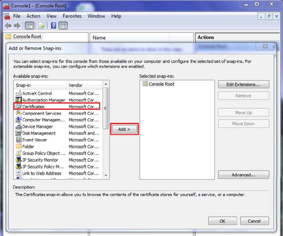
1)OpenMicrosoftManagementConsole‐Typemmcinsearchandpressenter
2)File‐>Add/RemoveSnap‐in
3)SelectCertificatesandpresstheAdd>button
4)SelecttheComputerAccountradiobutton
5)ChooseLocalcomputerthenpresstheFinishButton
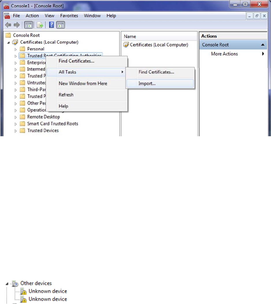
6)ImporttheprswigigusbcertificationtoTrustedRootandTrustedPublishers
a)Thecertificatecanbefoundin<build>\host\win\WinRelease_wlan\
b)Toimportthecertificate,right‐clickTrustedRootorTrustedPublishersandthenselectAllTasks‐>Import.
2.2InstallingtheHostandNetworkdriver
Inordertocreateanetwork,thePRS4601boardsmustbeconnectedtoahostcomputerwhichhasthe
appropriatedevicedriversinstalled.Atthetimeofwritingthisdocument,onlyhostcomputersrunningthe
Windows7operatingsystemwassupported.
2.2.1InstallingdriveronWindows7
Inordertoinstallthehostdrivers,ausermusthavethePRS4601devicewithavalidfirmwareimageprogramm
ed.
Thestepsforinstallingthehostdriveraredetailedbelow:
1.PluginthePRS4601devicetoaUSB3portonthehostcomputer.Immediatelythisprovidespowertothe
deviceandaflashinggreenstatusLEDindicatesthatthedeviceisreadyforuse.
2.NavigatetotheDeviceManageronthehostcomputer(RightclickonMyComputerandselectProperties.
AlinktotheDeviceManagercanbefoundintheleftpanelintheopenedwindow)
3.Twounknowndeviceshouldnowbevisibleunder“Otherdevices”(seeFigurebelow)
Figure2‐1:MissingdriverforpluggedinPRS4601device
4.RightclickonthefirstunknowndeviceandselectUpdateDriverSoftware
5.Select“Browsemycomputerfordriversoftware”thenbrowsetotheappropriatelocationofthedrivers.
6.SelectNexttostarttheinstallation
7.Aftertheinstallationcompletes,clicktheClosebutton
8.Repeatsteps4to7fortheremainingunknowndevice.
2.3Loadingimageontoboards
2.3.1Loadingimageontodevicefortheveryfirsttime
Thebootloaderisusedtoprogramtheboardsfortheveryfirsttime.ThePRS4601enablescommunicationwith
thebootloaderviatheUSBinterfaceassumingtheSerialdriverwasinstalled(seeSection2.2.1).TeraTerm(ora
ny otherterminalapplicationthatemulatescommunicationwithaCDCdevice)canbeusedtoverifycommunicatio
ntothebootloader.Theusercanpressedthe“Enter”keyorenterthe“version”commandandviewtheresponse.
Beforeprogrammingtheimage,theusermustdecidewhethertoloadtheimageto:
1.RAMinwhichcasetheprogramwouldbelostafterresettingthedevice
2.Flashinwhichcasetheprogramwouldbepersistedevenafterresettingthedevice
Note:IfthestatusLEDonPRS4601isblinkingagreenpattern,youcanskipthisstepandgotosection2.3.2.When
installingthefirmwareforthefirsttimethebootloadermustberunning–thisisindicatedwithaflashingyellow
LED.
Thedownload_elf.exeutilityisusedtoloadtheimagetoRAMonly.Thisutilitymustbeexecutedfromthesame
directorythathasthefirmwareimages.Note:Pleaseensuretorunthisutilityasanadministratorbyrightclicking
onthedownload_elf.exefileandselectingoptionto“RunasAdministrator”.
Thedownload_flash.exeutilityisusedtoloadtheimagetoFlash.Similarly,thisutilitymustbeexecutedfromthe
samedirectorythathasthefirmwareimages.Note:Pleaseensuretorunthisutilityasanadministratorbyright
clickingonthedownload_flash.exefileandselectingoptionto“RunasAdministrator”.
Note:Forthemajorityofuserscenarios,option#2wouldgenerallybepreferred.
2.3.2Loadingimageontodevicethatalreadyhaveapriorimage
Theimageontheboardcanbeupgradedordowngradedbydoubleclickingtheprs_flash_bin.batscriptprovided
withthefirmwareimage.Theboardmustberesetforthenewimagetotakeeffect.
2.4CreatingaNetworkwithtwoPRS4601s
WhenattemptingtocreateanetworkbetweentwoPRS4601s(wiredorwireless),theusermaychooseto
configureaspecificnodeasthenetworkcoordinator(moreappropriatelyknownasthePCPinan802.11adPBS
Snetwork)whileconfiguringtheothernodeasaStation(STA).Alternately,ausermayalsooptforhavingtheP
CPandSTAselectionsbenegotiatedallowingthedevicestochooseamongthemselvestheroleeachnodewillp
lay.
2.4.1ConfiguringPCP/STAModes
InordertosetthenodetoPCPorSTAmode,wewillneedtousetheDeviceManager.
TheDeviceManagercanbefoundunderControlPanel‐>DeviceManager.
Findthecorrectnetworkadapter,rightclick‐>properties.
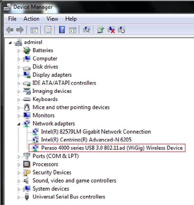
Figure2‐2:Devicemanager
Then,gototheadvancedtabandset:
AMSDU‐>ON
DeviceMode‐>PCPorSTA
Repeatthesestepsforbothnodes,onewithDeviceModesettoPCP,theotherwithDeviceModesettoSTA.
2.4.2Creatinganetworkprofile
Afterconfiguringdiscoverymodeonbothhostcomputers,thenextstepwillbetocreateaprofileforthenetwo
rk.
ThiswillneedtobedoneonthenodesettoPCPmode.Thestepsfordoingthisisoutlinedbelow.
1.OpentheNetworkandSharingCenterfromControlPanel
2.Clickonthe“Managewirelessnetwork”linkontheleftpanelforthewindow
3.ClickAddthenchoose“Createanadhocnetwork”.
4.ChoosetheNextbuttonafterreadingthedescriptionforsettingupawirelessadhocnetwork
5.Fillouttheformwhichisusedtoprovidedetailsaboutnetwork(seeFigurebelow)
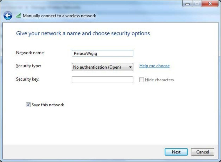
Figure2‐3:Creatinganetworkprofile
6.ClicktheNextbuttonafterfillingform
7.Clicktheclosebuttonafternetworkisreadyforuse(seeFigurebelow)
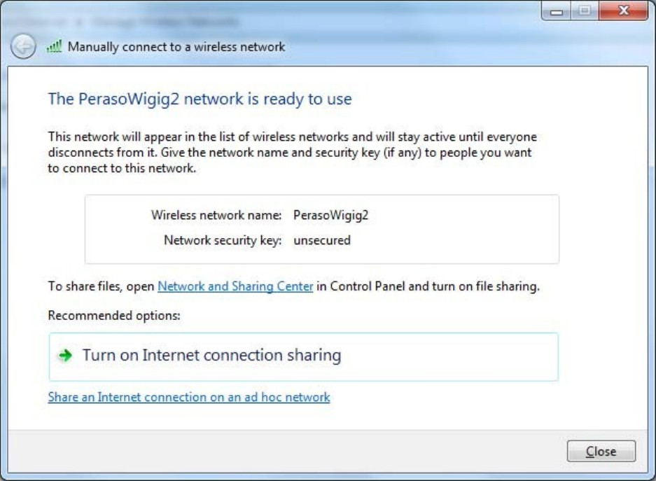
Figure3‐2‐4:Networkprofilesuccessfullycreate
2.4.3Startingandconnectingtocreatednetwork
ThenetworkmustbestartedfromthenodethatissettoPCP.FromthetrayiconsclickontheiconforWireless
Connection.Thisshoulddisplaythenetworkthatwascreatedabove.Doubleclickonthenetworkname(orRight
ClickandchooseConnect)tostartthenetwork.Oncestartedyoushouldnoticethestatuschangeto“Waitingfor
users”(seeFigurebelow)
TheusercanalsoknowthatthenetworkhasbeenstartedbylookingonthePRS4601device.Therewillbeafast
blinkingpatternofthegreenTXLEDindicatingthatframes(inthiscasebeacons)arebeingtransmittedbythe
device.
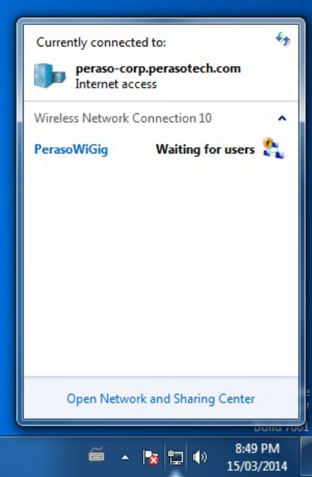
Figure3‐2‐5:StatusafterstartingPCP
FromthehostcomputerconfiguredtobeaSTA,thenetworkshouldnowbevisiblewhentheuserclicksonthe
wirelessconnectiontrayicon.Theusercanthendoubleclickonthenetworktheywishtoconnectto.Note:this
stepisthesameasconnectingtoanywirelessnetwork.
Ifconnectionwassuccessful,thestatuswillbeupdatedtoConnectedonbothhostcomputers.
2.4.4SettingstaticIPaddressesforhostmachines
WhileeachnodeonthenetworkwillbegivenanIPaddressautomatically,staticIPaddressescanbeconfigured
foreachhost.Thisisnotrequiredfortraffictobesentoverthenetwork.SettingstaticIPaddressescanbedone
fromtheAdapterpropertiesforthedevice(sameasanyothernetworkdevice)andselectingtheInternetProtocol
Version4(TCP/IPv4)properties.EnsurethatdifferentIPaddressesareusedforbothdevices.Figure#belowshows
theconfiguringofstaticaddressesforoneofthehostmachines
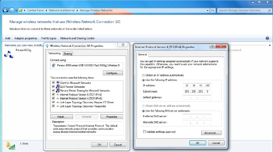
Figure3‐2‐6:ConfiguringstaticIPaddresses
3.Appendix
3.1AppendixA‐ EnablingDriverSigning
Ifevertheuserwantstostopusingacomputerasahostmachine,theycandisabletestmodewiththefollowing
steps:
1)Runcommandpromptasadministrator(entercmd.exeinsearchfield,rightclickonit)
2)Enterthefollowingtwolines
a)bcdedit.exe–setloadoptionsENABLE_INTEGRITY_CHECKS
b)bcdedit.exe‐setTESTSIGNINGOFF
3.2AppendixB–SettingupTeraTerm
ThestepstoconfigureTera Termonfirstusearedescribedbelow.
1.OpenthepreviouslydownloadedTeraTermapplication
2.NavigatetoSetup‐>Terminalandapplythefollowingsetting(s)
oReceive:AUTO
oCheck“LocalEcho”
3.NavigatetoSetup‐>SerialPortandapplythefollowingsetting(s)
oBaudRate:115200
4.SavethechangesbynavigatingtoSetup‐>SaveSetup
Next,youwillwanttopluginPRS4601viaUSB.Ifyouseeaflashingyellowlight,youwillneedtoinstallnew
firmware.Ifyouseeagreenlight,youcanupdateexistingfirmware.Ifthereisnolightvisible,PRS4601isnot
poweredon,andnothingwillwork.
Ineithercase,openupTeraTermandchoosethecorrectserialport.
Pressenterafewtimes.Ifthereisnofirmware,youwillgetasimplemessageafterthesecondenterpress,butno
commandswillwork.
IfyouhaveagreenlightonPRS4601,thefollowingcommandswillgivesomeoutputtoTeraTerm:
FCCStatement:
This device complies with Part 15 of the FCC Rules. Operation is subject to the
following two conditions: (1) This device may not cause harmful interference, and
(2) this device must accept any interference received, including interference that
may cause undesired operation.
FCC Caution: Any changes or modifications not expressly approved by the
party responsible for compliance could void the user’s authority to operate this
equipment.
IMPORTANT NOTE:
FCC Radiation Exposure Statement:
This equipment complies with FCC radiation exposure limits set forth for an
uncontrolled environment. This equipment should be installed and operated with minimum
distance 56 cm between the radiator & your body.
IMPORTANT NOTE:
This module is intended for OEM integrator only and limited to host with brand: IgniteNet and model:
ML-60-35, ML-60-35-1. The OEM integrator is still responsible for the FCC compliance requirement
of the end product, which integrates this module.
USERS MANUAL OF THE END PRODUCT:
In the users manual of the end product, the end user has to be informed to keep at least 56 cm
separation with the antenna while this end product is installed and operated. The end user has to
be informed that the FCC radio-frequency exposure guidelines for an uncontrolled environment can
be satisfied.
The end user has to also be informed that any changes or modifications not expressly approved by
the manufacturer could void the user's authority to operate this equipment.
LABEL OF THE END PRODUCT:
The final end product must be labeled in a visible area with the following " Contains TX FCC ID:
HED-ML60MDSB ".

The FCC part 15.19 statement below has to also be available on the label: This device complies
with Part 15 of FCC rules. Operation is subject to the following two conditions: (1) this device may
not cause harmful interference and (2) this device must accept any interference received, including
interference that may cause undesired operation.
This Module may not be integrated into host devices that are addressed for operation inside
airplanes/satellites.
Antenna list:
Ant.BrandP/NAntenna
TypeConnectorGain(dBi)
1Accton123400001084ADishAnt.N/A42
ICStatement:
This device complies with Industry Canada license-exempt RSS standard(s). Operation is subject
to the following two conditions: (1) this device may not cause interference, and (2) this device must
accept any interference, including interference that may cause undesired operation of the device.
Le présent appareil est conforme aux CNR d'Industrie Canada applicables aux appareils radio
exempts de licence. L'exploitation est autorisée aux deux conditions suivantes : (1) l'appareil ne
doit pas produire de brouillage, et (2) l'utilisateur de l'appareil doit accepter tout brouillage
radioélectrique subi, même si le brouillage est susceptible d'en compromettre le fonctionnement.
IMPORTANT NOTE:
IC Radiation Exposure Statement:
This equipment complies with IC RSS-102 radiation exposure limits set forth for an
uncontrolled environment. This equipment should be installed and operated with minimum distance
20 cm between the radiator & your body.
Cet équipement est conforme aux limites d'exposition aux rayonnements IC établies pour un
environnement non contrôlé. Cet équipement doit être installé et utilisé avec un minimum de 20 cm
de distance entre la source de rayonnement et votre corps.
IMPORTANT NOTE:
This module is intended for OEM integrator only and limited to host with brand: IgniteNet and model:
ML-60-35, ML-60-35-1. The OEM integrator is still responsible for the IC compliance requirement of
the end product, which integrates this module.
Any changes or modifications not expressly approved by the manufacturer could void the user's
authority to operate this equipment.
USERS MANUAL OF THE END PRODUCT:
In the users manual of the end product, the end user has to be informed to keep at least 20 cm
separation with the antenna while this end product is installed and operated. The end user has to
be informed that the IC radio-frequency exposure guidelines for an uncontrolled environment can
be satisfied. The end user has to also be informed that any changes or modifications not expressly
approved by the manufacturer could void the user's authority to operate this equipment. Operation
is subject to the following two conditions: (1) this device may not cause harmful interference and (2)
this device must accept any interference received, including interference that may cause
undesired operation.
LABEL OF THE END PRODUCT:
The final end product must be labeled in a visible area with the following " Contains IC:
3857A-ML6035G3 ".
The Host Model Number (HMN) must be indicated at any location on the exterior of the end product
or product packaging or product literature which shall be available with the end product or online.