Accton Technology OAP3211A 802.11a outdoor CPE (Client) User Manual
Accton Technology Corp 802.11a outdoor CPE (Client)
User Manual
SU-A-MB-12-EZ CPE for BreezeACCESS VL Quick Installation Guide
1
P/N: October 2006
This Quick Installation Guide is intended for experienced installers. For more information refer to the relevant sections in the
BreezeAccess VL System Manual.
ODU CPE Package Content
Check that the package contains:
• ODU CPE Outdoor Unit (with integral antenna)
• A wall and pole mounting kit
• Mains power cord (this item is packed separately from the IDU package).
• This Quick Installation Guide
Tilt Accessory Kit (Optional)
Ordered separately.
Additional Equipment and Tools Required for Installation
• Ethernet cable for connecting to the user’s data equipment (crossed for connecting to a hub/switch, straight for connecting
to a PC)
• Indoor-to-outdoor Category 5E Ethernet cable. Use only Category 5E cables approved by the supplier. The length of the
Indoor-to-Outdoor cable should not exceed 90 meters. The length of the Indoor-to-Outdoor cable, together with the length
of the Ethernet cable connecting the CPE-IDU-1D to the data equipment, should not exceed 100 meters.
• Two shielded RJ-45 connectors
• Grounding cable with an appropriate termination.
• Mains plug adapter or termination plug (if the power plug on the supplied AC power cord does not fit local power outlets).
• Portable PC/Notebook and a straight Ethernet cable for configuring parameters using Telnet. TFTP server SW is required
for downloading SW versions. OR portable PC/Notebook or Pocket PC/PDA and a straight Ethernet cable for configuring
parameters using a web browser
• Installation tools and materials, including appropriate means (e.g. a pole) for installing the outdoor unit (and antenna where
applicable) and for sealing any outdoor connectors.
• To connect directly to the ODU for configuration/performance monitoring: A special Y-cable and a Notebook or PDA with
web browser.
• Optional SU Alignment Unit (SAU) for easy alignment of the antenna.
WARNING: ONLY experienced installation professionals who are familiar with local building and safety codes and,
wherever applicable, are licensed by the appropriate government regulatory authorities should install outdoor
units and antennas. Failure to do so may void the product warranty and may expose the end user or Service
Provider to legal and financial liabilities. The manufacturer and its resellers or distributors are not liable for
injury, damage or regulation violations associated with the installation of outdoor units or antennas.
Equipment Location Guidelines
The antenna should provide a direct, or near line of sight, with the Base Station antenna. The higher the placement of the
antenna, the better the achievable link quality. The location of the ODU should enable easy access to the unit for installation and
testing.
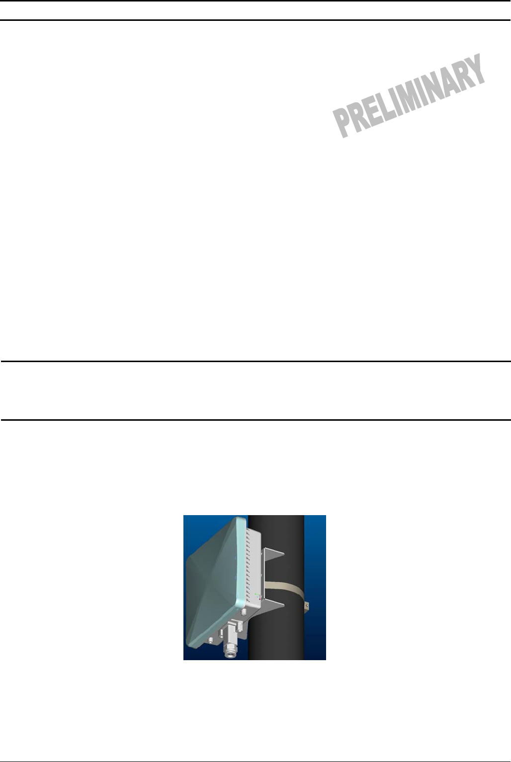
ODU Installation
Mount the ODU unit using the clamp, band and screws supplied with the unit. The unit’s antenna is polarized vertically in the
direction of the RJ45 port. Install the unit with the connectors facing downwards as shown in the following image.
ODU CPE for BreezeACCESS VL Quick Installation Guide
2
P/N: October 2006
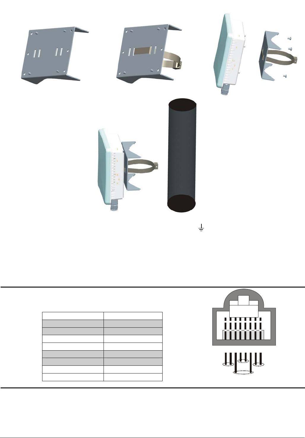
1. Thread the provided metal band through the adaptor bracket and use the screws provided with the mounting kit to attach
the adaptor bracket to the unit.
2. Connect a grounding cable between the Ground terminal of the ODU (marked ) and a good ground connection.
3. Align the unit using the LED display.
Preparing the IDU-ODU Cable
Use a crimp tool for RJ-45 connectors to prepare the wires. Insert them into the appropriate pins and use the tool to crimp the
connector. Make sure to do the following:
• Remove as small a length as possible of the external jacket. Verify that the external jacket is well inside the sealing
cover when connected to the unit, to ensure good sealing.
• Pull back the shield drain wire before inserting the cable into the RJ-45 connector, to ensure a good connection with
the connector's shield after crimping.
The following diagram shows the required wire pair pin-to-pin connections,
including the color codes used in cables supplied by the manufacturer.
Wire color Pin
Blue 1
Blue/white 2
Orange 3
Orange/white 6
Brown 4
Brown/white 5
Green 7
Green/white 8
Connecting the IDU-ODU Cable
1. Remove the sealing cap of the ODU connector.
2. The sealing cap has a special groove allowing to insert an Ethernet cable with an already assembled RJ-45 connector
through the cap. To expose the groove, lightly squeeze the cap. Carefully insert the cable with the assembled connector
through the groove.
12345678
1 + 2 4 + 5 7 + 8
3 + 6

ODU CPE for BreezeACCESS VL Quick Installation Guide
3
P/N: October 2006
3. Connect the Ethernet cable to the ODU RJ-45 connector.
4. Put the sealing cap back in its place to ensure protection against moisture. Make sure that the small protrusion on the side
of the cap fits inside the hole on the connector’s protective body.
5. Use appropriate sealing material to protect the connection against moisture and humidity. Use high quality sealing material
such as Scotch® 130C Linerless Rubber Splicing Tape from 3M to ensure IP-67 compliant protection against dust and
water.
6. Route the cable to the location selected for the indoor equipment.
7. Assemble an RJ-45 connector with a protective cover on the indoor end of the ODU cable. Refer to the pin assignment and
color codes in standard cables described below.
IDU Installation
1. The unit can be placed on a desktop or a shelf. Alternatively, it may be wall-mounted. The drilling template included with the
unit can be used to simplify the wall installation process.
2. Connect the ODU cable to the RADIO port.
3. Connect the indoor unit to the AC mains using the power cord supplied with the unit.
NOTE: The indoor unit should be connected to the power source only after it has been connected to the outdoor unit.
The color codes of the power cord are:
Brown Phase ~
Blue Neutral 0
Yellow/green Grounding
4. Use a crossed Ethernet cable to connect the ETHERNET port to a Hub/Switch. Use a straight Ethernet cable to connect
directly to a PC’s NIC.
Basic Configuration
1. Initial configuration can be performed using either Telnet for accessing the Installer Monitor program or a web browser for
accessing the built-in Web Configuration Server.
2. To configure parameters using Telnet, connect a PC/Notebook to the Ethernet port of the IDU, using a straight Ethernet
cable.
3. To configure parameters using the Web Configuration Server, connect a PC/Notebook or a Pocket PC/PDA with a web
browser to the Ethernet port of the IDU, using a straight Ethernet cable.
4. You can also connect directly to the ODU’s IDU COM, using the special Y-cable (see instructions below).
5. Configure the PC's IP parameters to enable connectivity with the unit. The IP address of the SU for local management
access is 192.168.254.251. The Subnet Mask is 255.255.255.0. The recommended IP address for the PC is
192.168.254.250, as this is also the default TFTP Sever IP Address (required for downloading SW versions and for
downloading/uploading configuration files).
6. Run the Telnet program or open a web browser, and connect to 192.168.254.251. The Enter the password prompt is
displayed. Enter the password (the default password is “installer”) and press the Enter key.
7. Configure the basic parameters required for connectivity with the base station. The following table includes the basic
parameters and their default values:
Table 1: Basic Parameters
Parameter Default Value Comment
Ethernet Port auto Negotiation
Enable/Disable Enabled
Ethernet Port Speed and Duplex Applicable only if Ethernet Port Auto Negotiation
Enable/Disable is set to Disable
User Name Null Must be supplied by system administrator
User Password Null Must be supplied by system administrator
Organization Name Optional – according to administrator policy
Address Optional– according to administrator policy
Country Optional– according to administrator policy
BST/AU ID 186.190.0.0.250.206
BST/AU ID Mask 255.255.255.0.0.0
Best BST/AU Support Disable
Preferred BST/AU ID
Preferred BST/AU ID Mask
Bandwidth 3.5 MHz
Scanning Start Frequency Depend on Radio Band and
Bandwidth
Scanning End Frequency Depend on Radio Band and
Bandwidth
Scanning Main Step 875 KHz
Scanning Intermediate Steps
Bits 0 to 7 0 for all eight bits
Discrete Frequencies Null
Rx Attenuator (2.3 GHz units
only) 0

ODU CPE for BreezeACCESS VL Quick Installation Guide
4
P/N: October 2006
8. Reset the unit to apply the changes.
Aligning the Antenna
1. Point the antenna toward the general direction of the Base Station.
2. Connect the SAU to the ODU (optional) and verify that the PWR (power) indication on the SAU is on.
3. Verify that the unit is synchronized with a Base Station. If the SU is not synchronized with a Base Station, ensure that all
parameters are configured properly. If the unit is still not synchronized with a Base Station, improve the quality of the link by
changing the direction of the antenna or by placing the antenna at a higher or in an alternate location.
4. Rotate (and/or tilt if applicable) the ODU/antenna until the maximum link quality reading is achieved (SNR and RSSI, or
when using SAU, the number of link quality LEDs). If you encounter prolonged difficulty in achieving the expected link
quality, try to improve the reception quality by placing the antenna at a higher point or in an alternate location.
5. Ensure that the front of the antenna is always facing the Base Station. However, in certain conditions, such as when the line
of site to the Base Station is hampered, better reception may be achieved using a reflected signal. In this case, the antenna
is not always directed toward the Base Station.
6. Secure the unit firmly to the pole.
NOTE: In some cases, the antenna may need to be tilted to ensure that the level at which the SU receives
transmissions from the AU (and vice versa) is not too high. When all LINK QUALITY LEDS are on,
including LED 10, this indicates that the received signal level is too high (saturation). This must be
avoided, preferably by up-tilting the antenna. As a rule of thumb, if the SU is located at a distance of less
than 300 meters from the AU, it is recommended to up-tilt the antenna by approximately 10° to 15°.
Fast Configuration and Antenna Alignment Using the Y-Cable
1. Disconnect the IDU-ODU cable from the ODU.
2. Connect one end of the Y-cable to the ODU’s IDU COM connector.
3. On the other end of the Y-cable, connect a PDA/PC to the PDA connector and the IDU-ODU cable to the IDU connector.
4. From the Pocket PC/Notebook, connect to the SU and complete the process of configuring basic parameters.
5. Align the antenna using the instructions above.
Verifying Proper Operation
1. Verify data connectivity by pinging the AU or by connecting to the Internet.
2. To verify proper operation of the SU, examine the LED indicators on the IDU:
Table 2: IDU LEDs
Name Description Functionality
Power Power Indication
Off – IDU is not powered or power failed
Green – IDU power is OK
Link Ethernet link status
(Ethernet integrity)
Off – No Ethernet connectivity has been detected between the
outdoor unit and the device connected to the indoor unit
Green – Ethernet connectivity has been detected between the
outdoor unit and the device connected to the indoor unit
11a Wireless link status Off – SU is not associated with an AU/μBST
Green – SU is connected with an AU/μBST
* After power-up, the WIRELESS LED illuminates until self-test is finished.
3. To verify proper operation of the ODU, examine the LEDs of the SAU:
Table 3: SAU LEDs
Federal Communication Commission Interference Statement
This equipment has been tested and found to comply with the limits for a Class B digital device, pursuant to Part 15 of the FCC
Rules. These limits are designed to provide reasonable protection against harmful interference in a residential installation. This
equipment generates, uses and can radiate radio frequency energy and, if not installed and used in accordance with the
instructions, may cause harmful interference to radio communications. However, there is no guarantee that interference will not
occur in a particular installation. If this equipment does cause harmful interference to radio or television reception, which can be
determined by turning the equipment off and on, the user is encouraged to try to correct the interference by one of the following
measures:
• Reorient or relocate the receiving antenna.
• Increase the separation between the equipment and receiver.
• Connect the equipment into an outlet on a circuit different from that to which the receiver is connected.
• Consult the dealer or an experienced radio/TV technician for help.

ODU CPE for BreezeACCESS VL Quick Installation Guide
5
P/N: October 2006
FCC Caution: Any changes or modifications not expressly approved by the party responsible for compliance could void the
user's authority to operate this equipment.
This device complies with Part 15 of the FCC Rules. Operation is subject to the following two conditions: (1) This device may not
cause harmful interference, and (2) this device must accept any interference received, including interference that may cause
undesired operation.
This device and its antenna(s) must not be co-located or operating in conjunction with any other antenna or transmitter.
IMPORTANT NOTE:
FCC Radiation Exposure Statement:
This equipment complies with FCC radiation exposure limits set forth for an uncontrolled environment. This equipment should
be installed and operated with minimum distance 20cm between the radiator & your body.
FCC NOTICE: To comply with FCC part 15 rules in the United States, the system must be professionally installed to ensure
compliance with the Part 15 certification. It is the responsibility of the operator and professional installer to ensure that only
certified systems are deployed in the United States. The use of the system in any other combination (such as co-located
antennas transmitting the same information) is expressly forbidden.
CE Statement:1177
Hereby, Alvarion, declares that this device is in compliance with the essential requirement and other relevant provisions of the
R&TTE Driective 1999/5/EC.
This device will be sold in the following EEA countries:Austria, Italy, Belgium, Liechtenstein, Denmark, Luxembourg, Finland,
Netherlands, France, Norway, Germany, Portugal, Greece, Spain, Iceland, Sweden, Ireland, United Kingdom, Cyprus, Czech
Republic, Estonia, Hungary, Latvia, Lithuania, Malta, Slovakia, Poland, Slovenia.
ODU CPE for BreezeACCESS VL Quick Installation Guide
6
P/N: October 2006
R&TTE Compliance Statement
This equipment complies with the appropriate essential requirements of Article 3 of the R&TTE Directive 1999/5/EC.