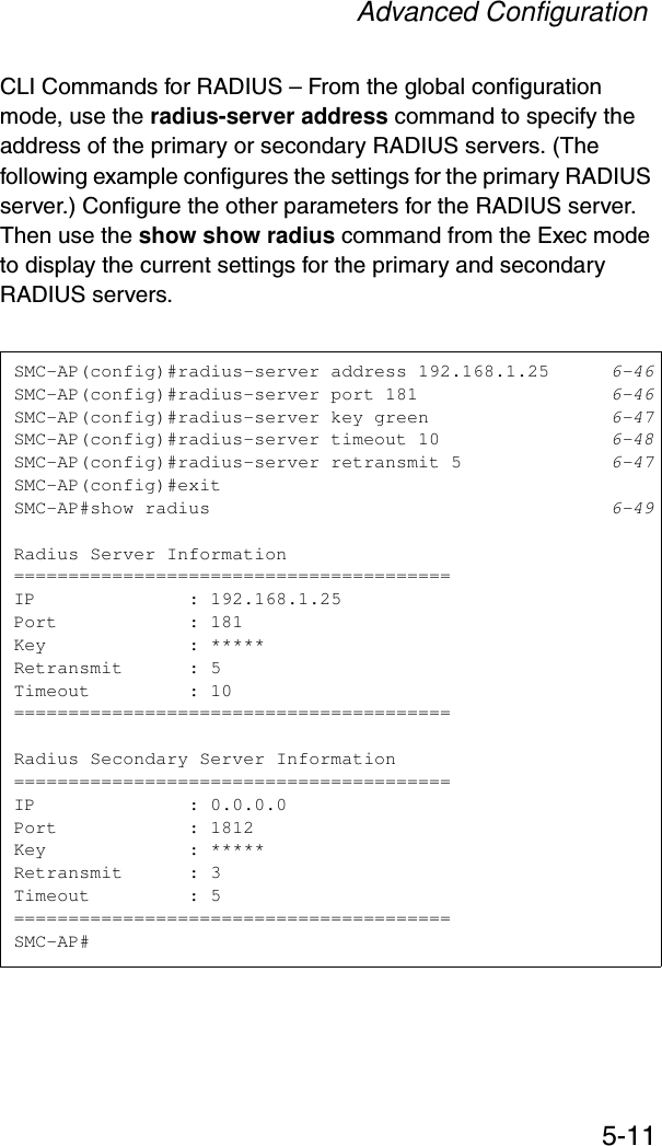
Accton Technology SMC2552WG EliteConnect 2.4GHz 802.11g Wireless Access Point User Manual WA4101 17MessAroundTakeTwo
Accton Technology Corp EliteConnect 2.4GHz 802.11g Wireless Access Point WA4101 17MessAroundTakeTwo
UserManual.wiki
>
Accton Technology
>
SMC2552WG User Manual
user manual
Navigation menu
Upload a User Manual
Namespaces
Wiki Guide
HTML
PDF
Info
Views
User Manual
Discussion / Help
Navigation


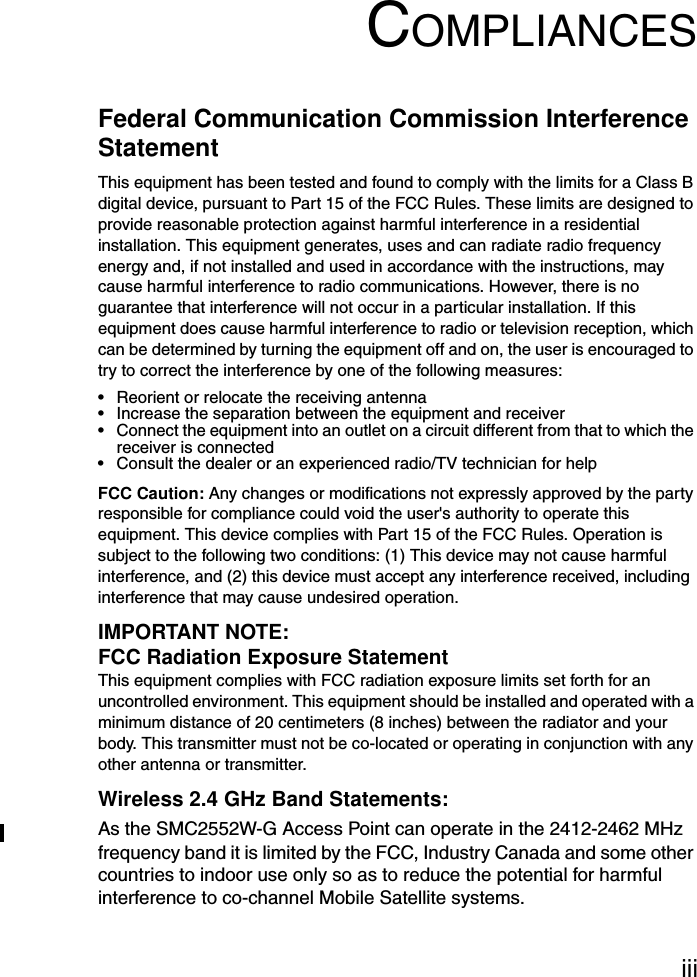


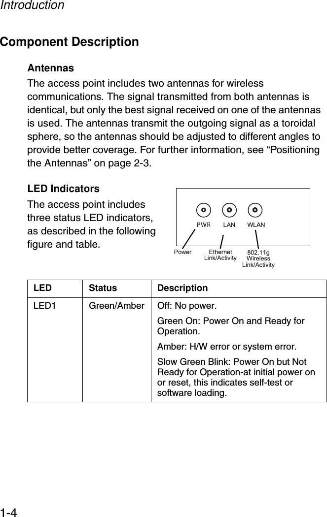
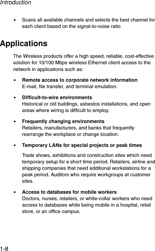
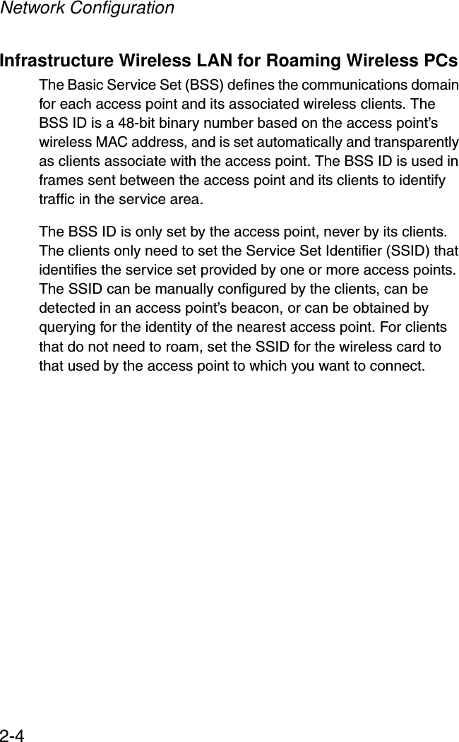


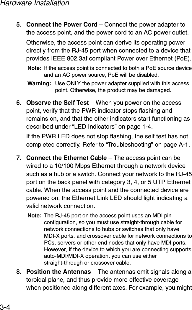

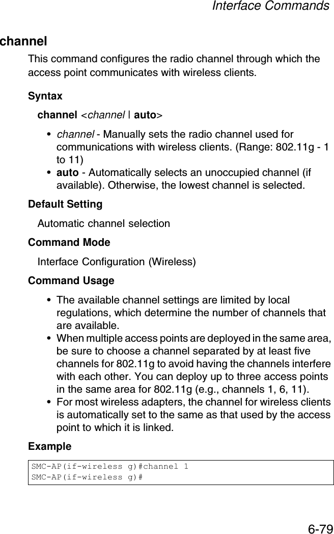
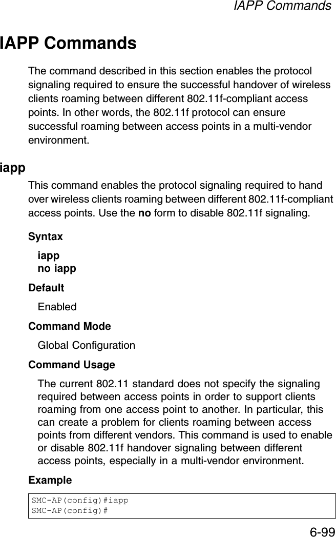
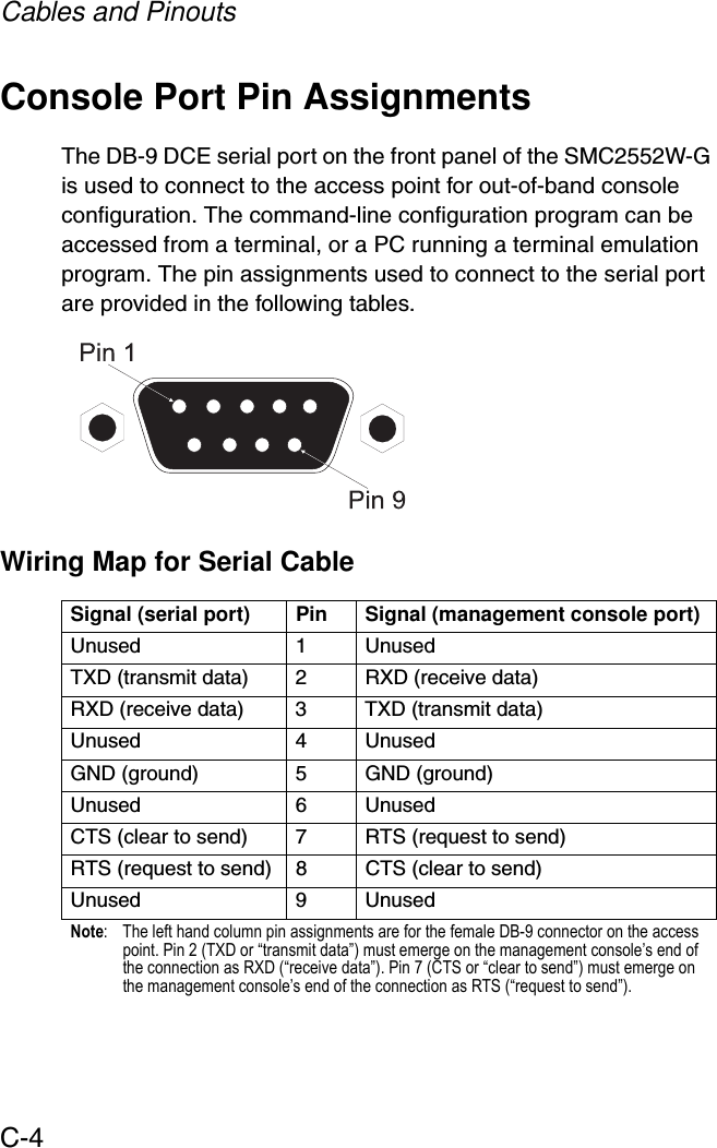
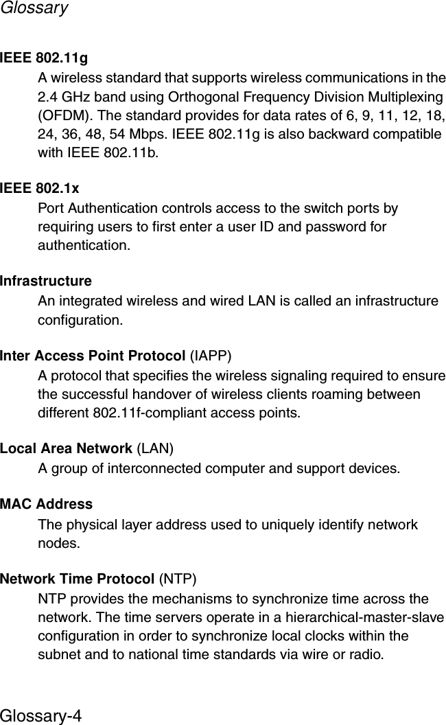
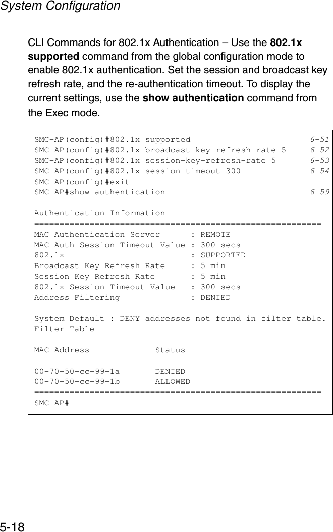
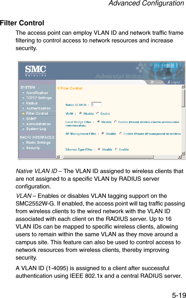
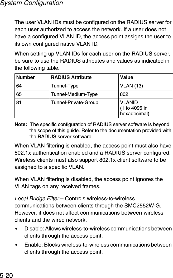
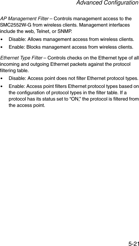
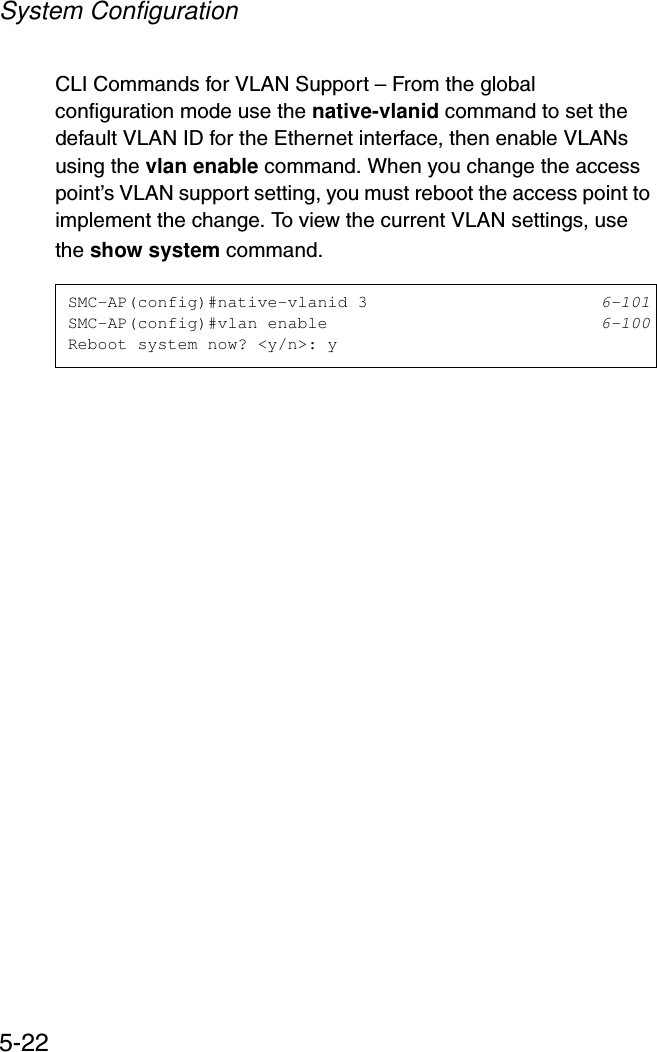
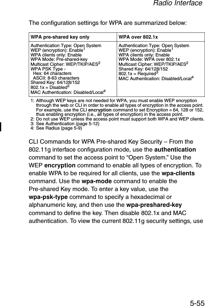
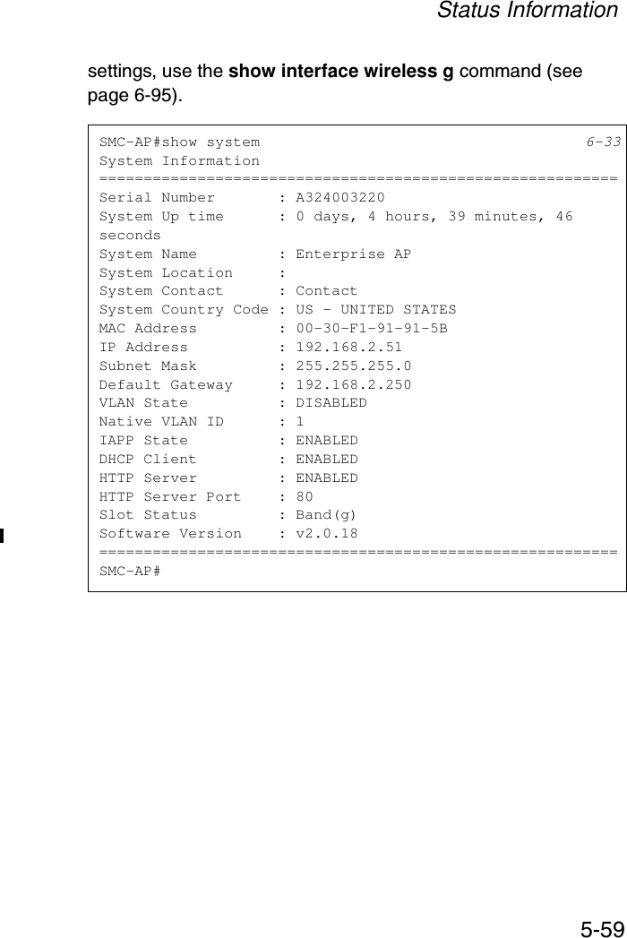
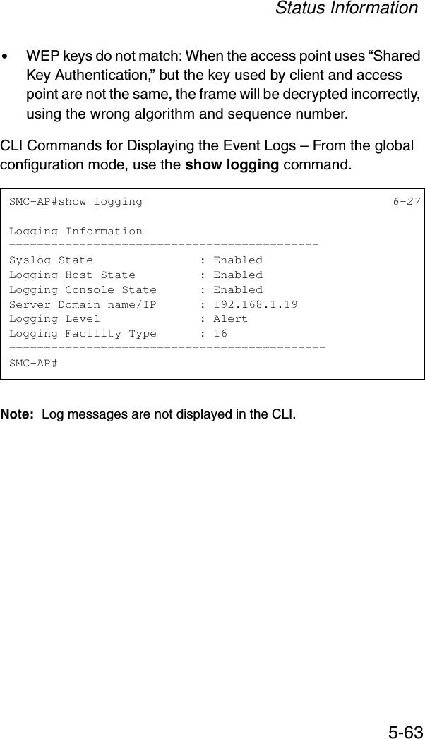
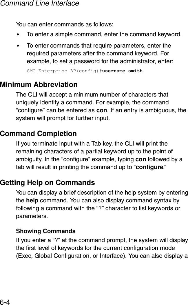
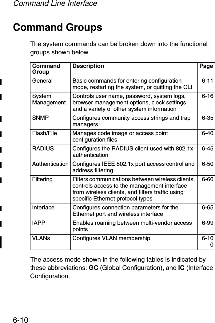
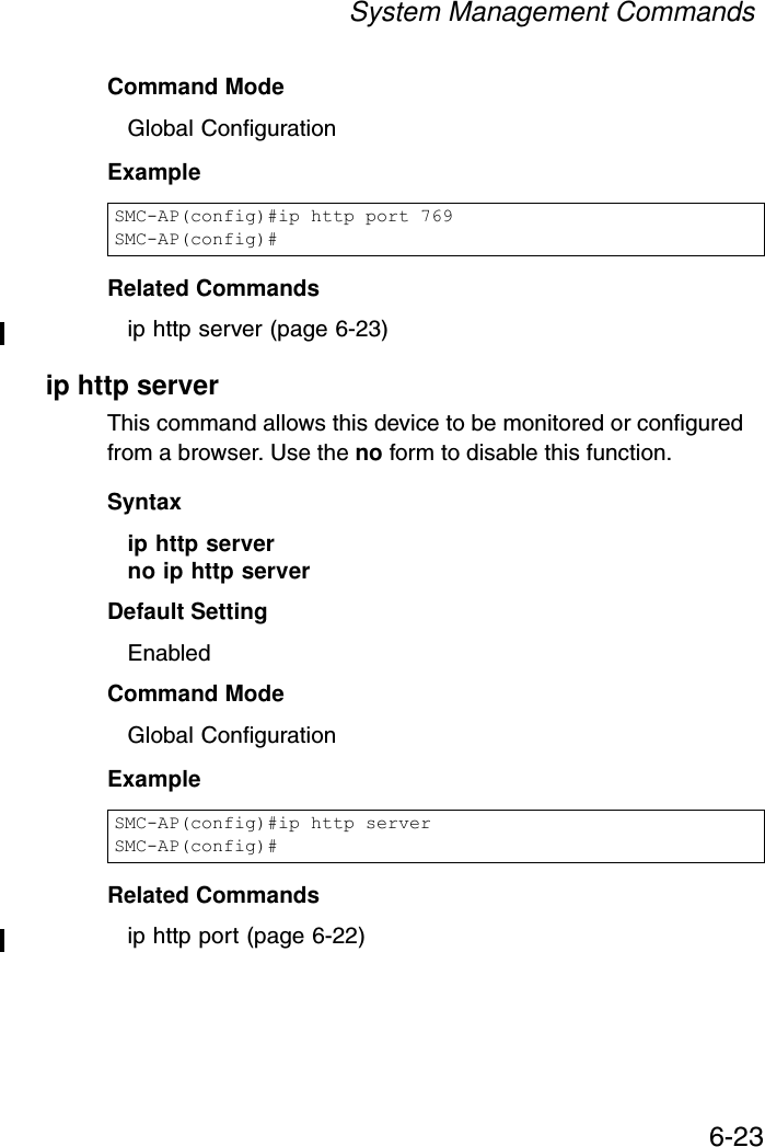
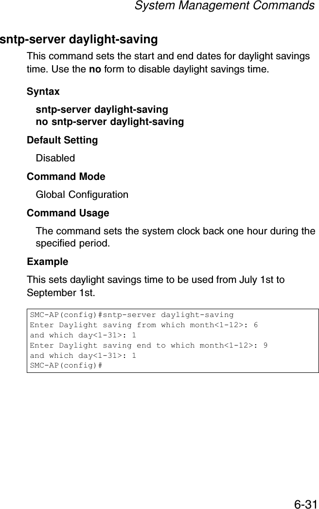
![Initial Configuration4-2To connect to the console port, complete the following steps:1. Connect the console cable to the serial port on a terminal, or a PC running terminal emulation software, and tighten the captive retaining screws on the DB-9 connector.2. Connect the other end of the cable to the RS-232 serial port on the access point.3. Make sure the terminal emulation software is set as follows:•Select the appropriate serial port (COM port 1 or 2).•Set the data rate to 9600 baud.•Set the data format to 8 data bits, 1 stop bit, and no parity.•Set flow control to none.•Set the emulation mode to VT100.•When using HyperTerminal, select Terminal keys, not Windows keys.Note: When using HyperTerminal with Microsoft® Windows® 2000, make sure that you have Windows 2000 Service Pack 2 or later installed. Windows 2000 Service Pack 2 fixes the problem of arrow keys not functioning in HyperTerminal’s VT100 emulation. See www.microsoft.com for information on Windows 2000 service packs. 4. Once you have set up the terminal correctly, press the [Enter] key to initiate the console connection. The console login screen will be displayed.For a description of how to use the CLI, see “Using the Command Line Interface” on page 6-1. For a list of all the CLI commands and detailed information on using the CLI, refer to “Command Groups” on page 6-10.](https://usermanual.wiki/Accton-Technology/SMC2552WG/User-Guide-396480-Page-40.png)
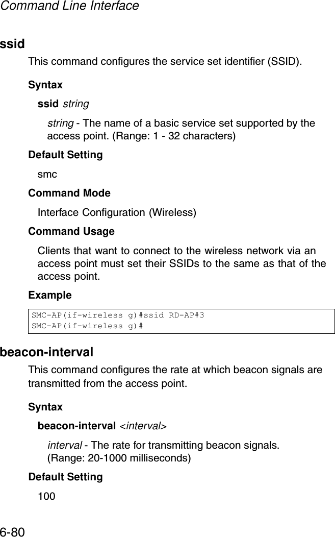
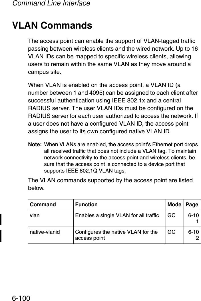
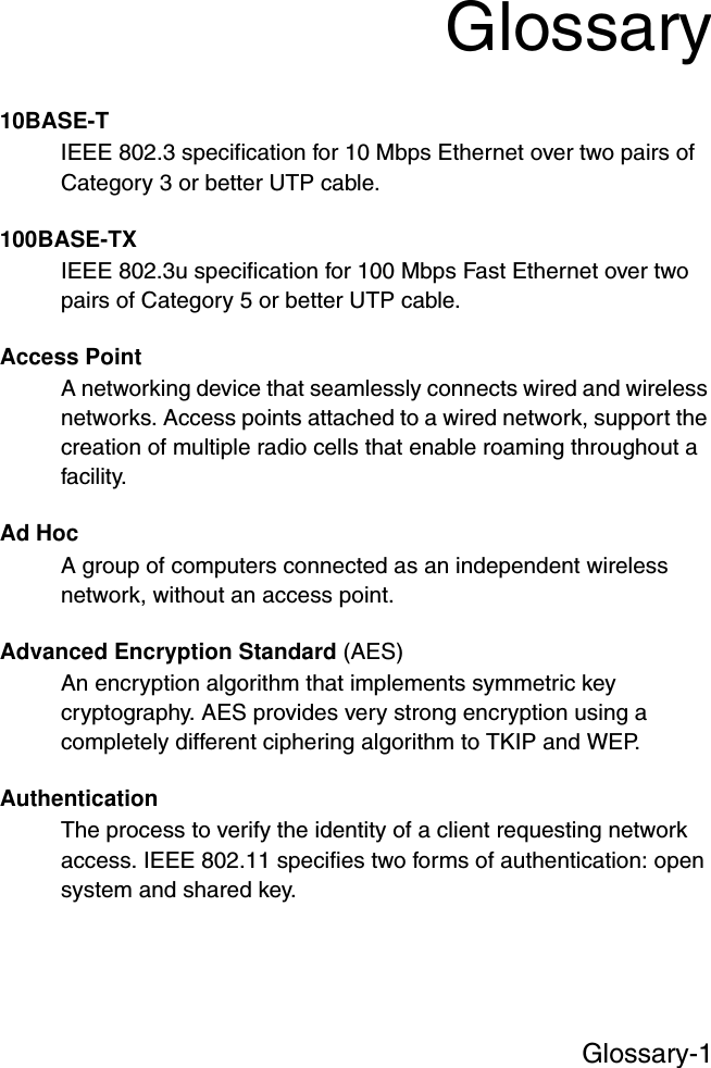
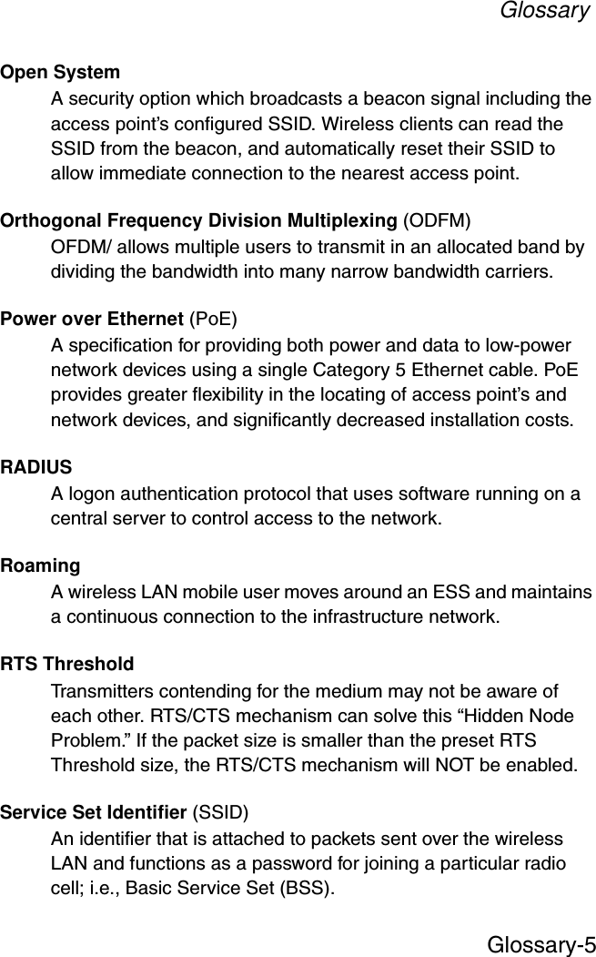
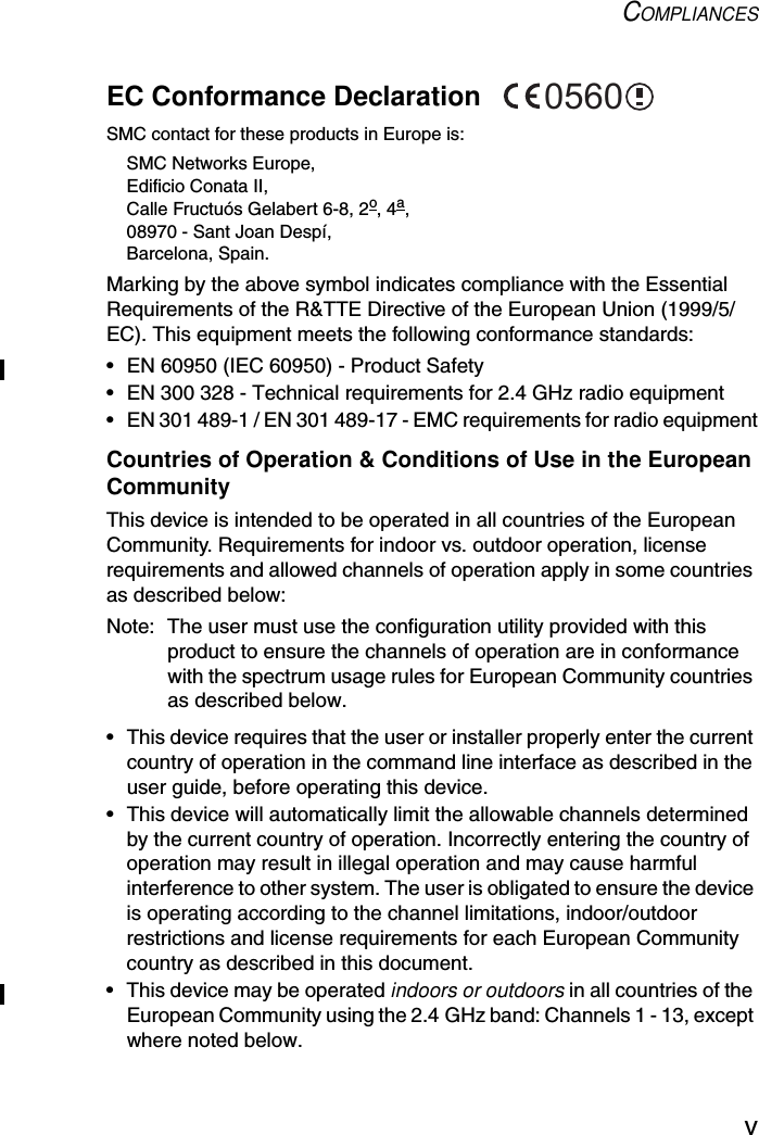
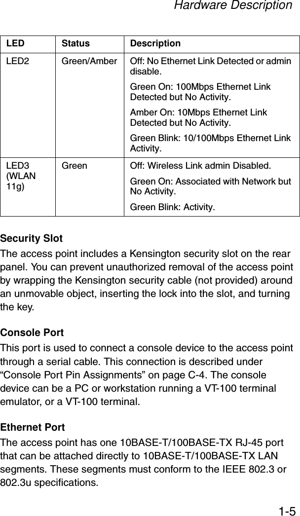
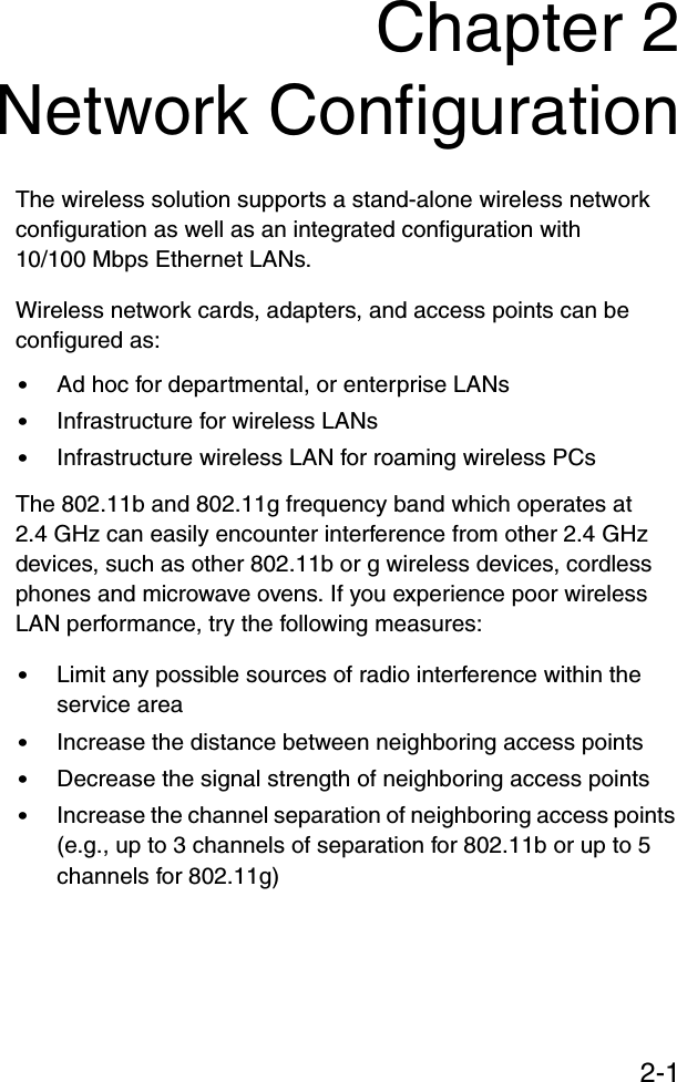
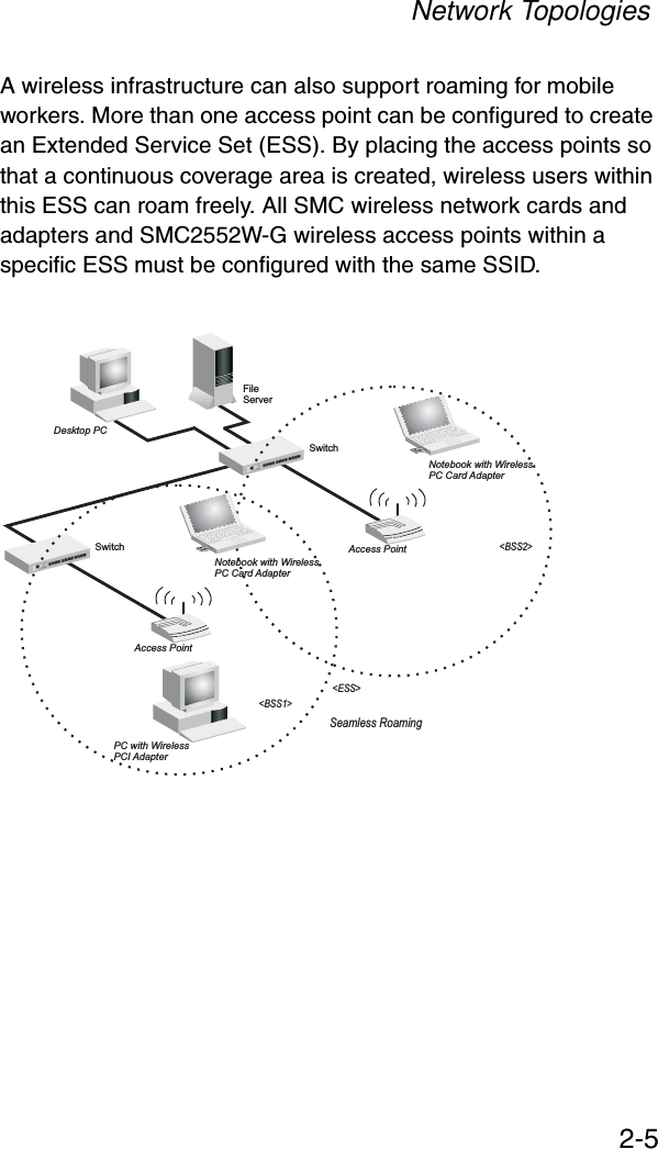
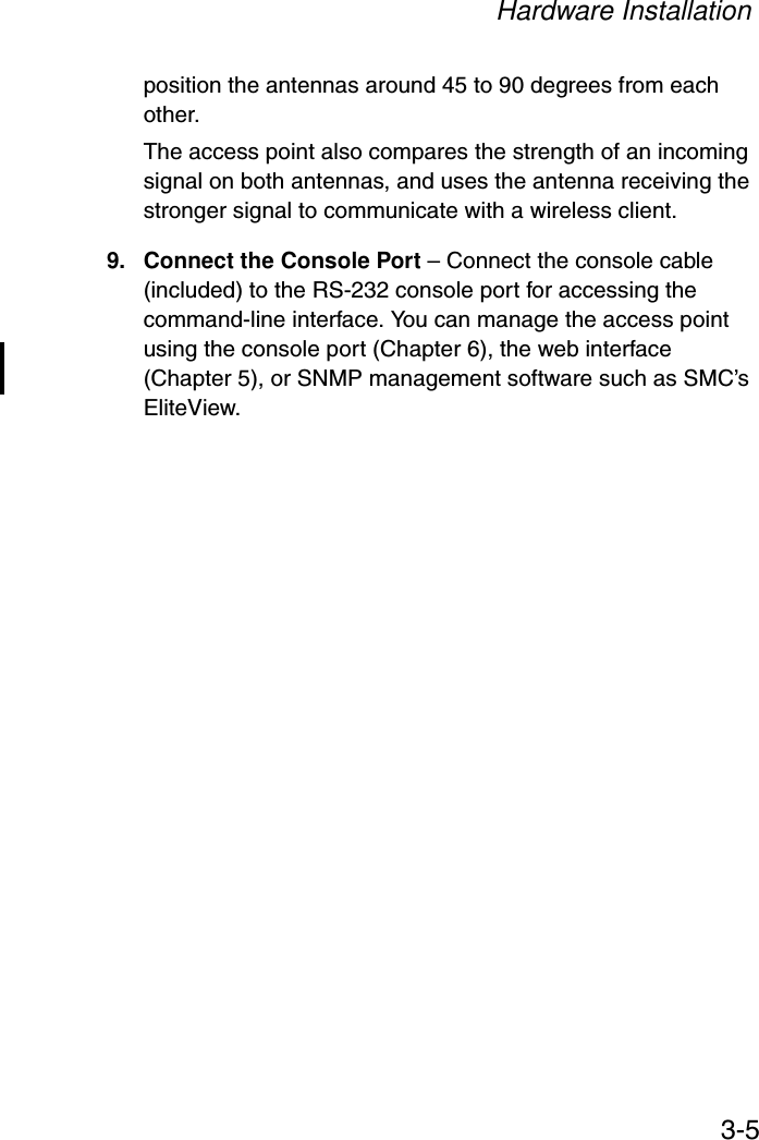
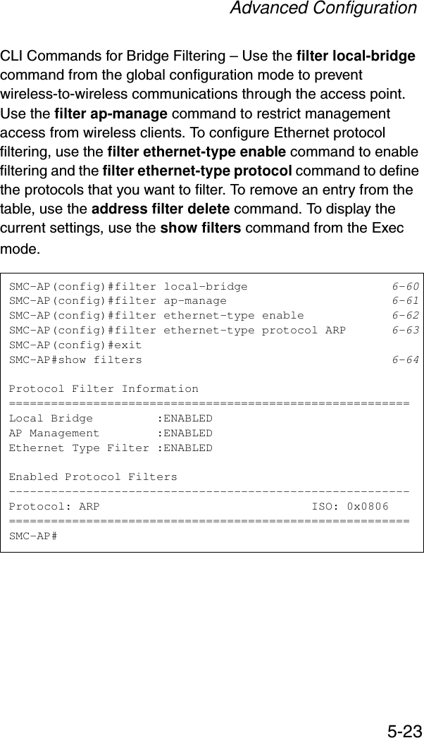
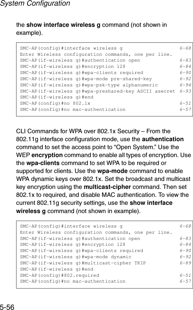
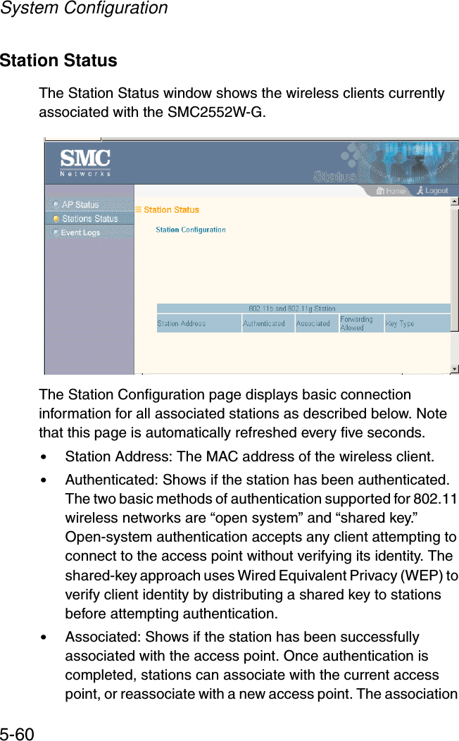
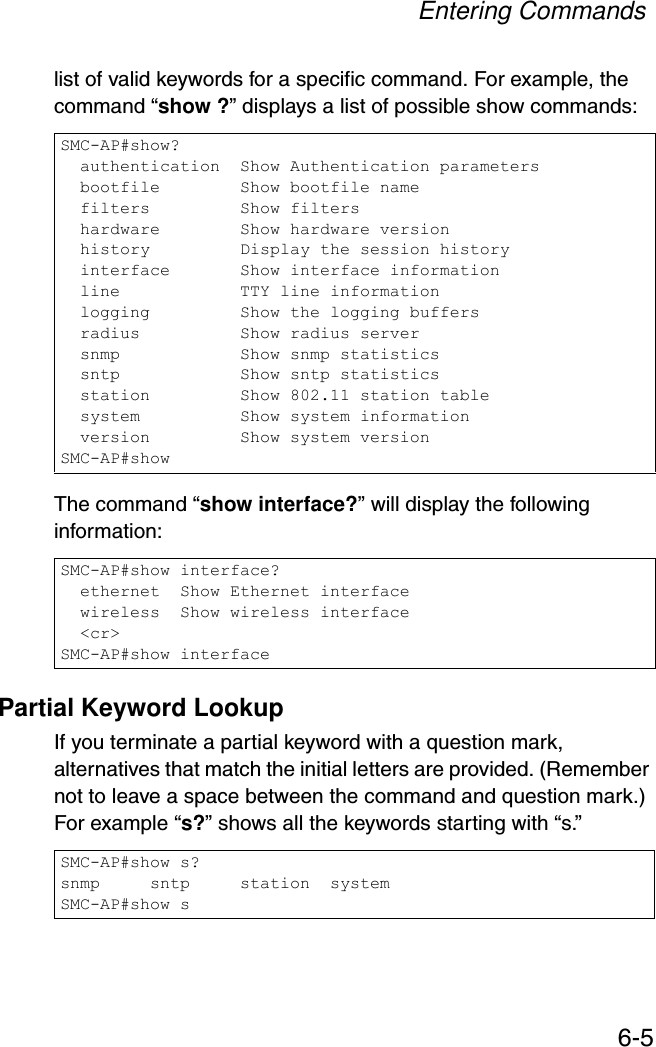
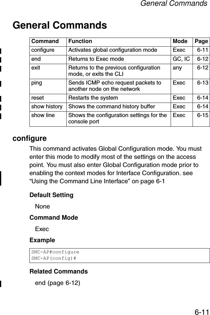
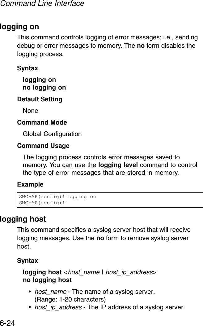
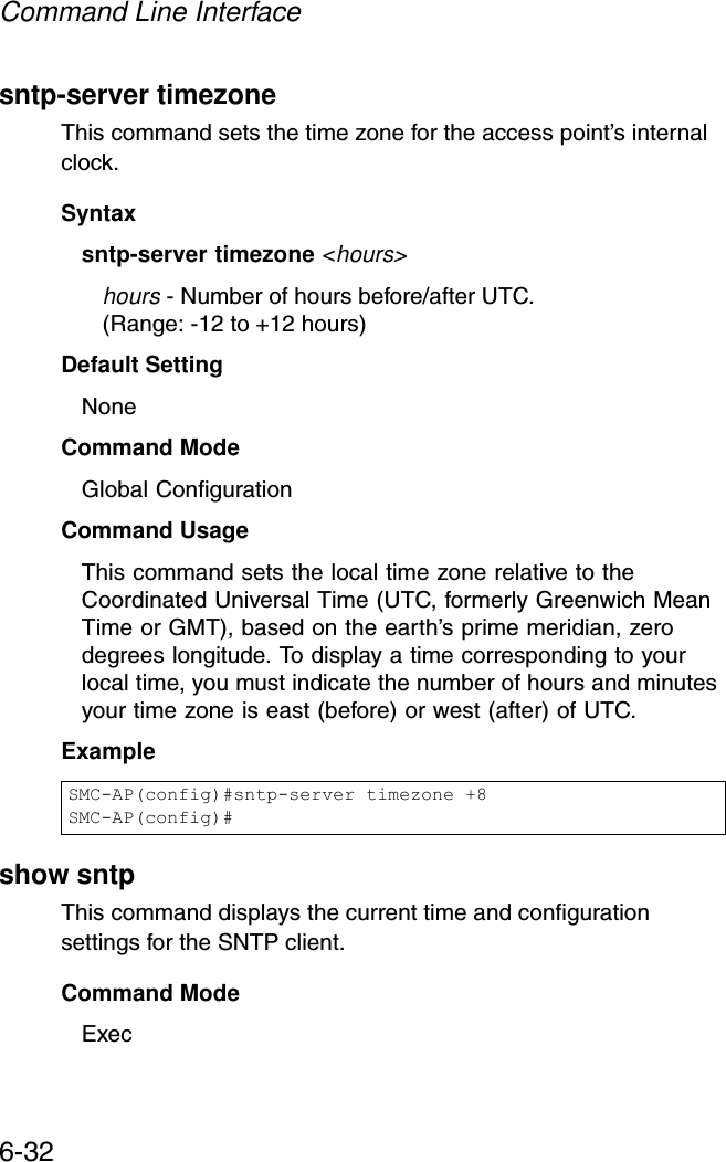
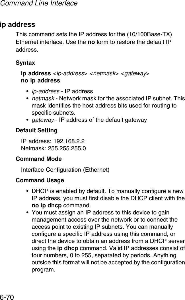
![Initial Setup through the CLI4-3Initial Configuration StepsLogging In – Enter “admin” for the user name. The default password is null, so just press [Enter] at the password prompt. The CLI prompt appears displaying the access point’s model number.Setting the IP Address – By default, the access point is configured to obtain IP address settings from a DHCP server. You will therefore have to use the command line interface (CLI) to assign an IP address that is compatible with your network. Type “configure” to enter configuration mode, then type “interface ethernet” to access the Ethernet interface-configuration mode.First type “no dhcp” to disable DHCP client mode. Then type “ip address ip-address netmask gateway,” where “ip-address” is the access point’s IP address, “netmask” is the network mask for the network, and “gateway” is the default gateway router. Check with your system administrator to obtain an IP address that is compatible with your network.After configuring the access point’s IP parameters, you can access the management interface from anywhere within the attached network. The command line interface can also be Username: adminPassword: smcadminSMC Enterprise AP#SMC Enterprise AP#configureSMC Enterprise AP(config)#interface ethernetSMC Enterprise AP(config-if)#SMC Enterprise AP(if-ethernet)#no dhcpSMC Enterprise AP(if-ethernet)#ip address 192.168.2.2 255.255.255.0 192.168.2.254SMC Enterprise AP(if-ethernet)#](https://usermanual.wiki/Accton-Technology/SMC2552WG/User-Guide-396480-Page-41.png)
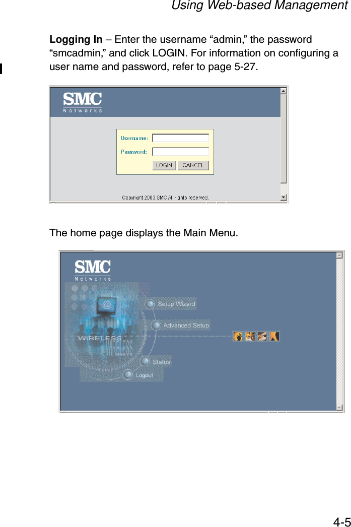
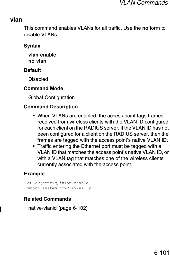
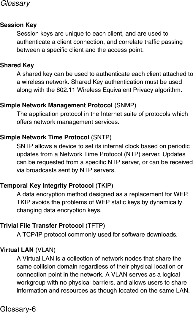
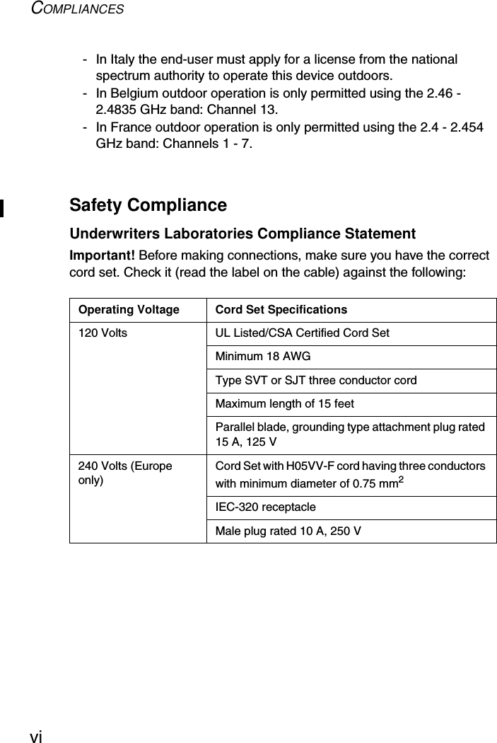
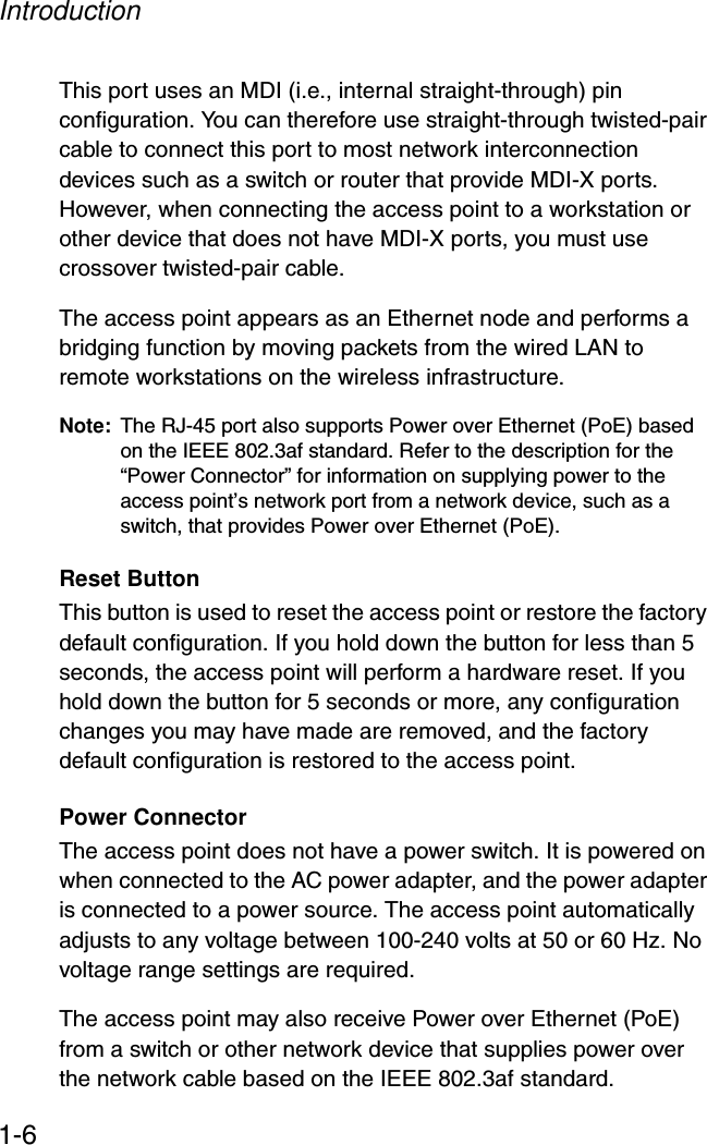
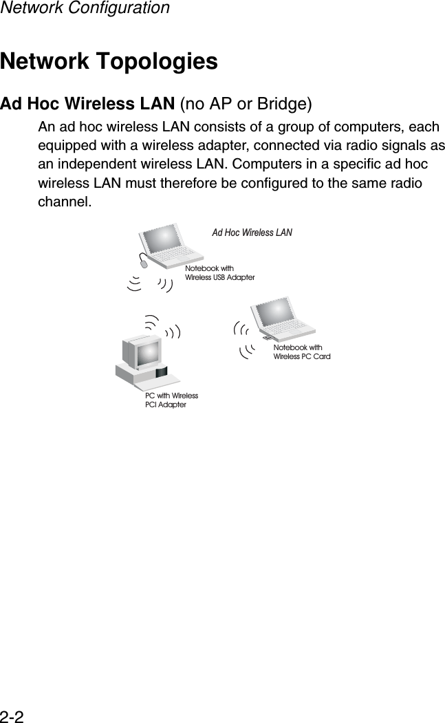
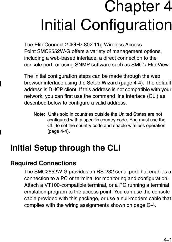
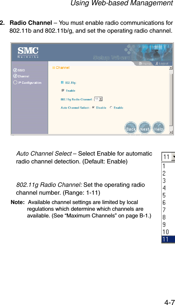
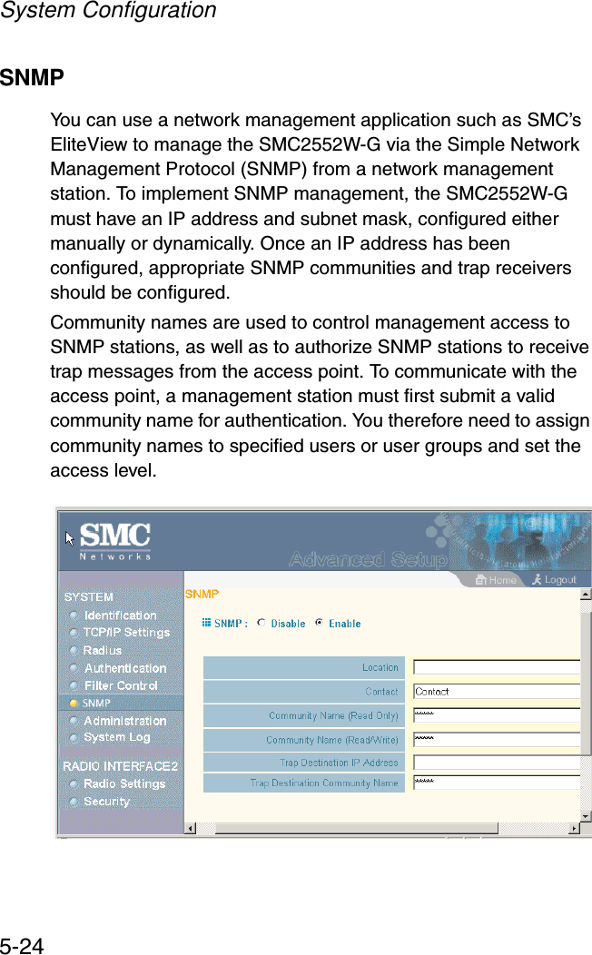
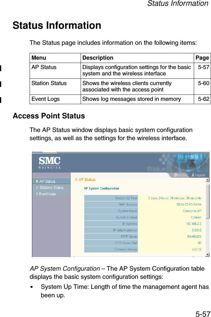
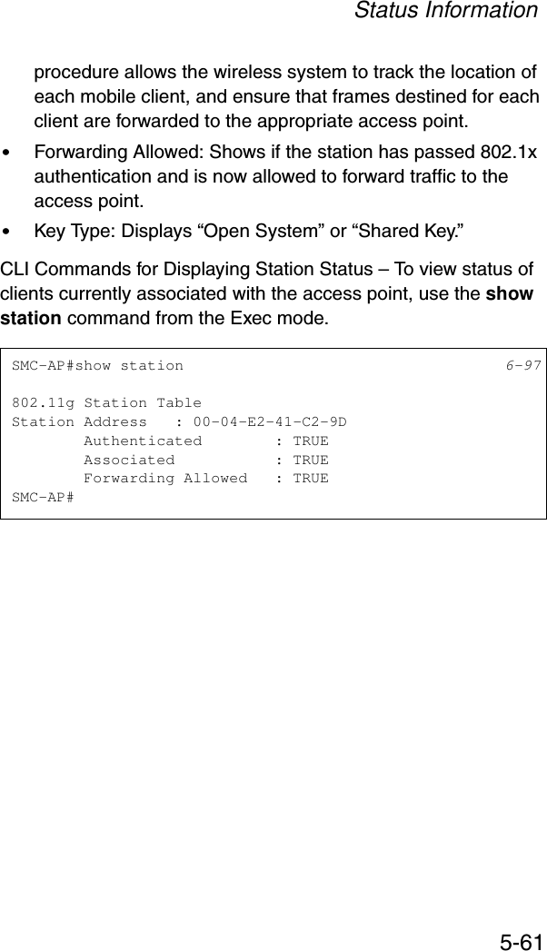
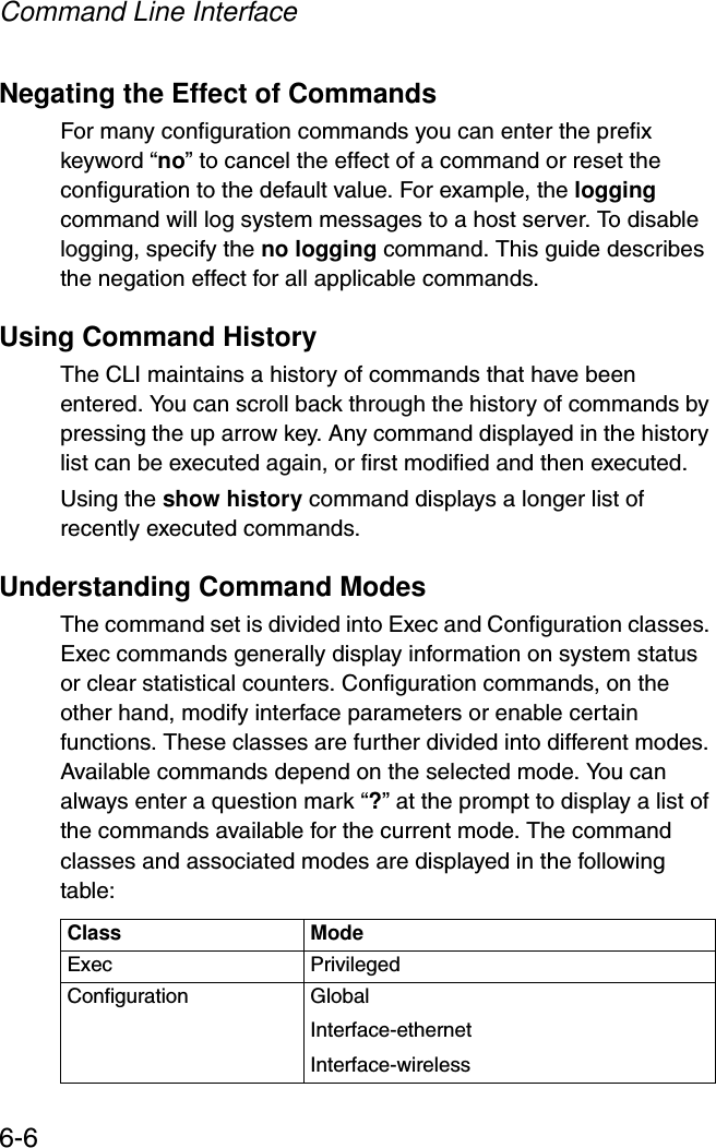
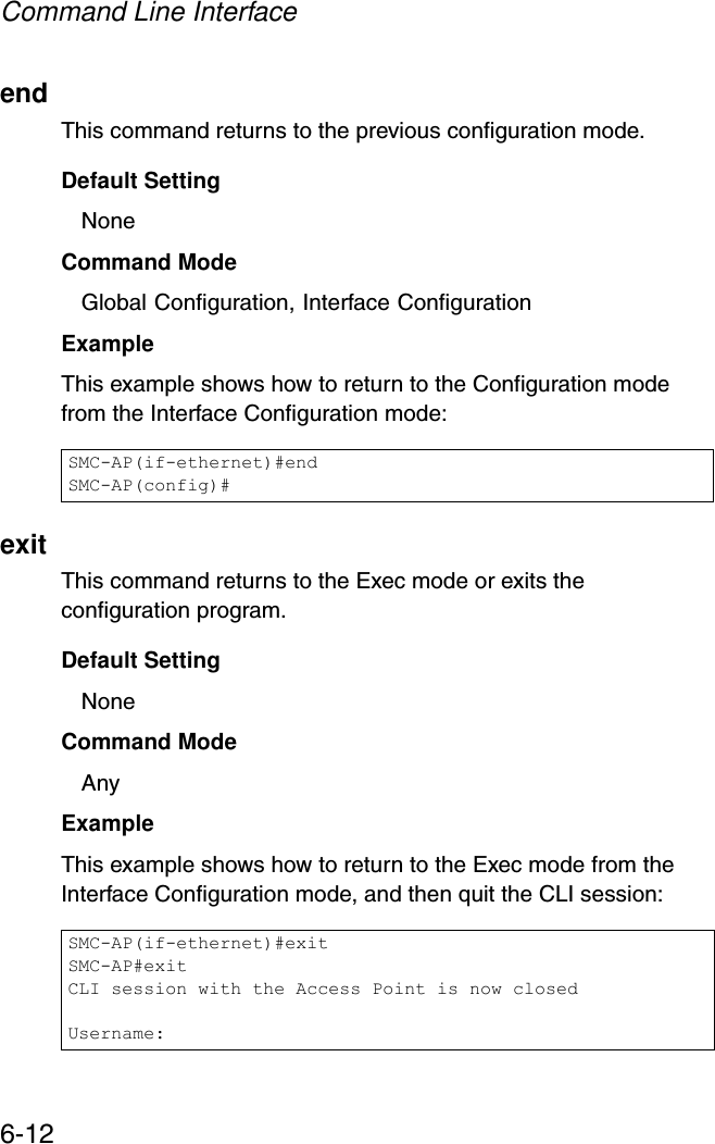
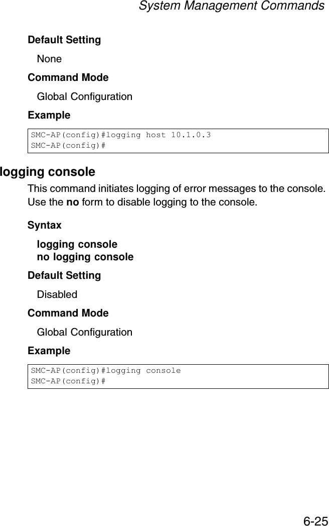
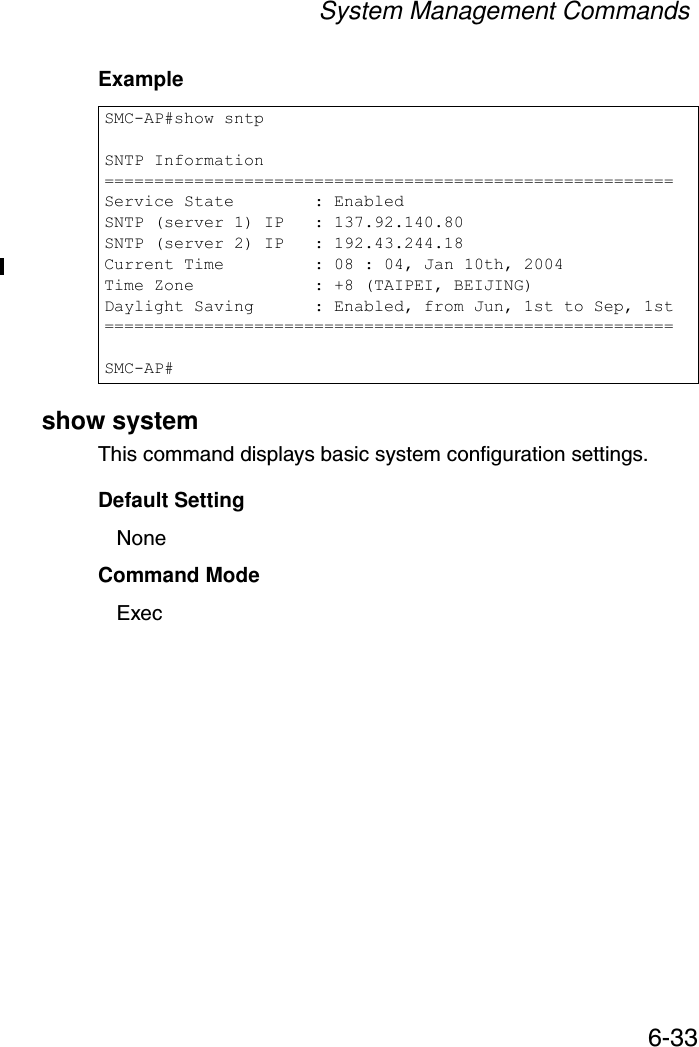
![Initial Configuration4-6Launching the Setup Wizard – To perform initial configuration, click Setup Wizard on the home page, then click on the [Next] button to start the process. 1. Service Set ID – Enter the service set identifier in the SSID box which all wireless clients must use to associate with the access point. The SSID is case sensitive and can consist of up to 32 alphanumeric characters. (Default: SMC)](https://usermanual.wiki/Accton-Technology/SMC2552WG/User-Guide-396480-Page-44.png)


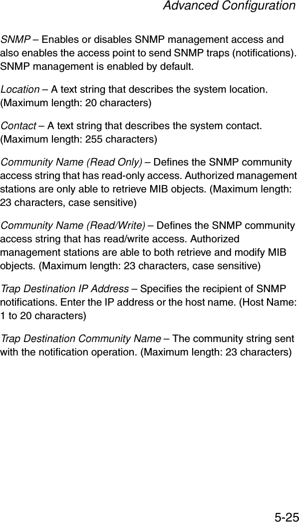
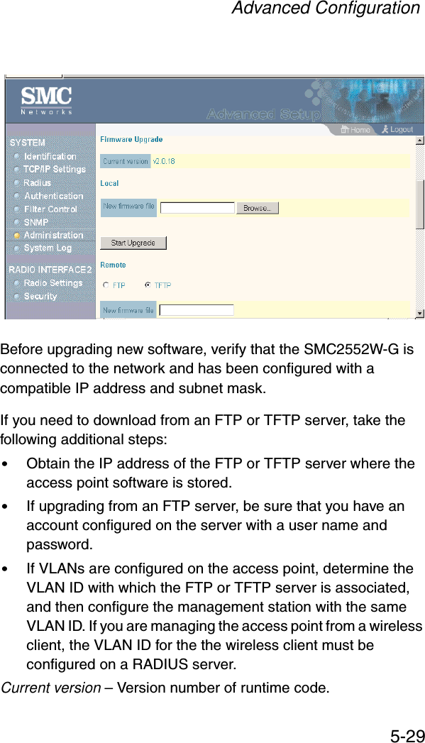
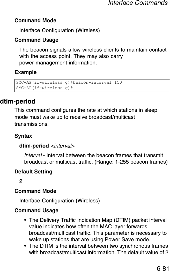
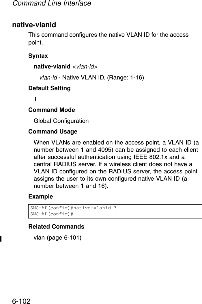
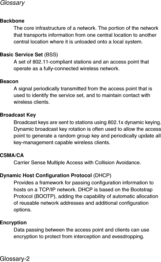
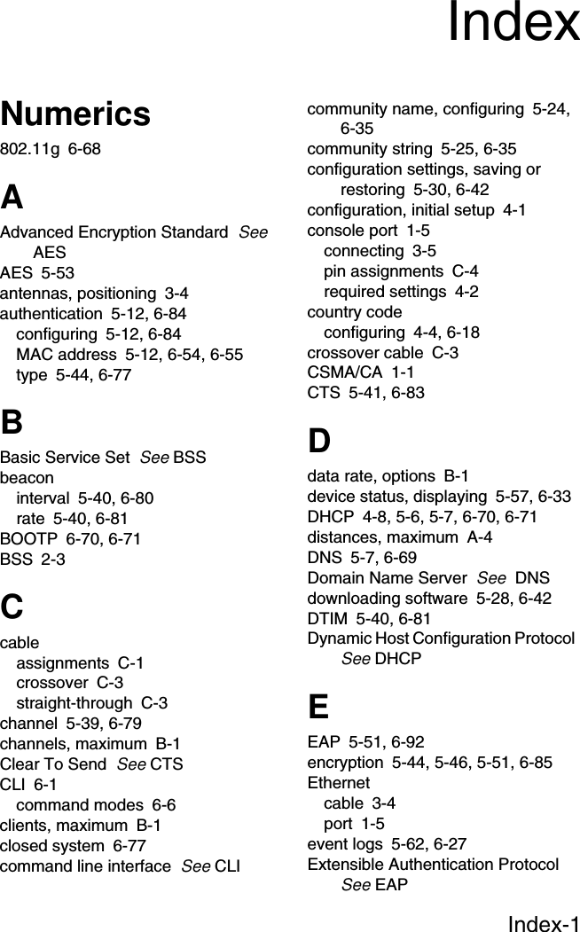
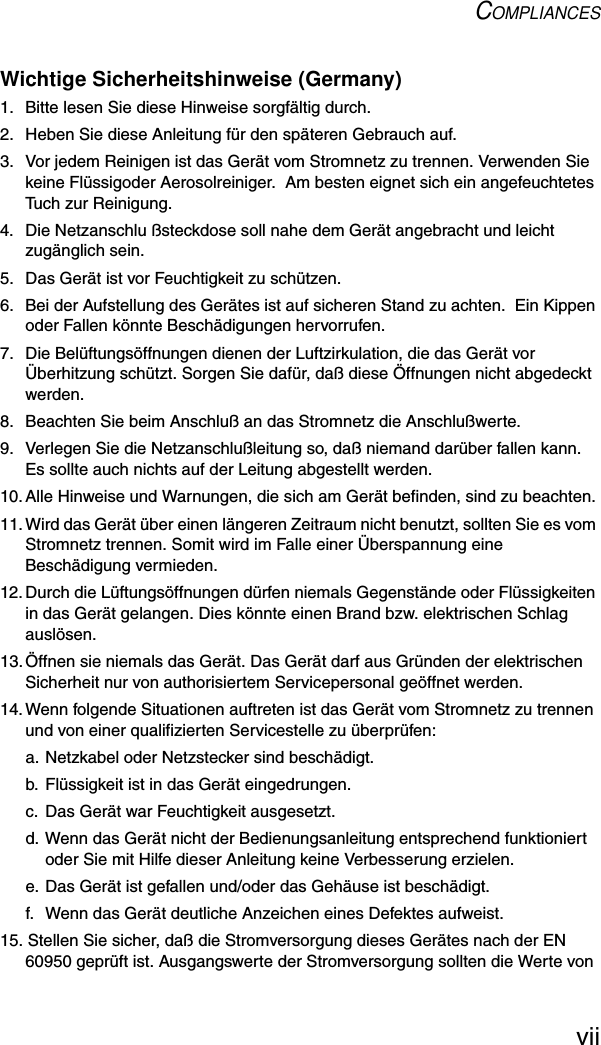
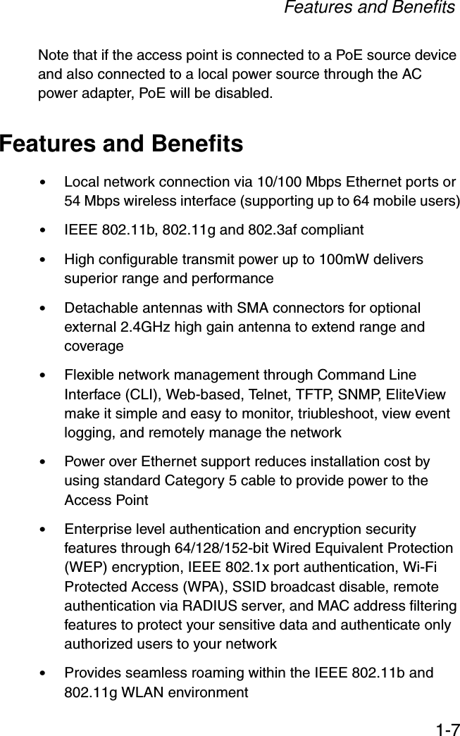
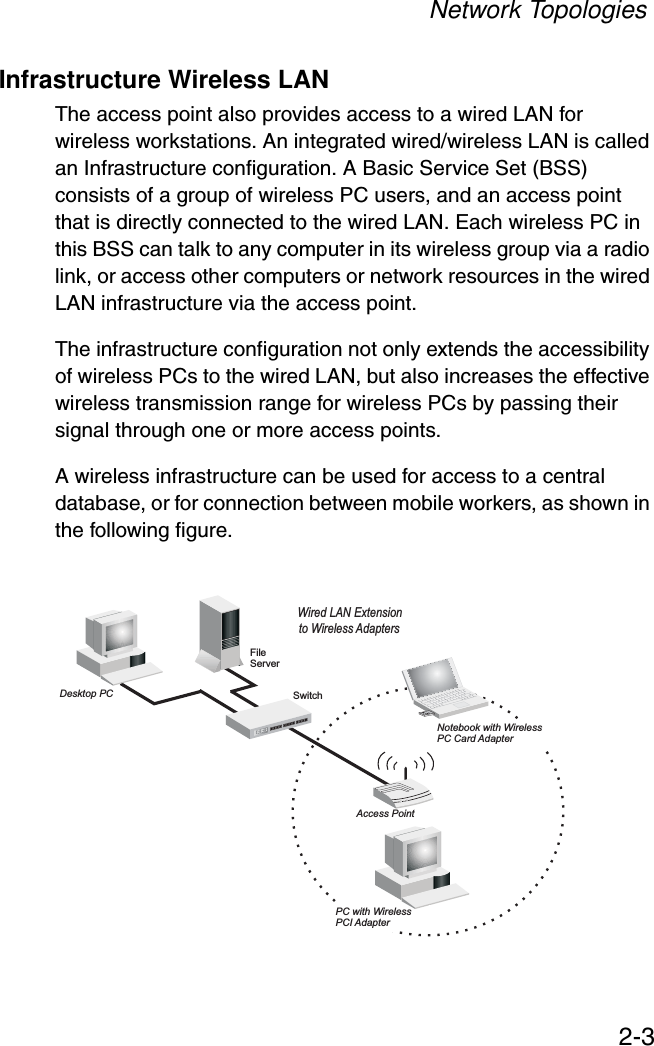
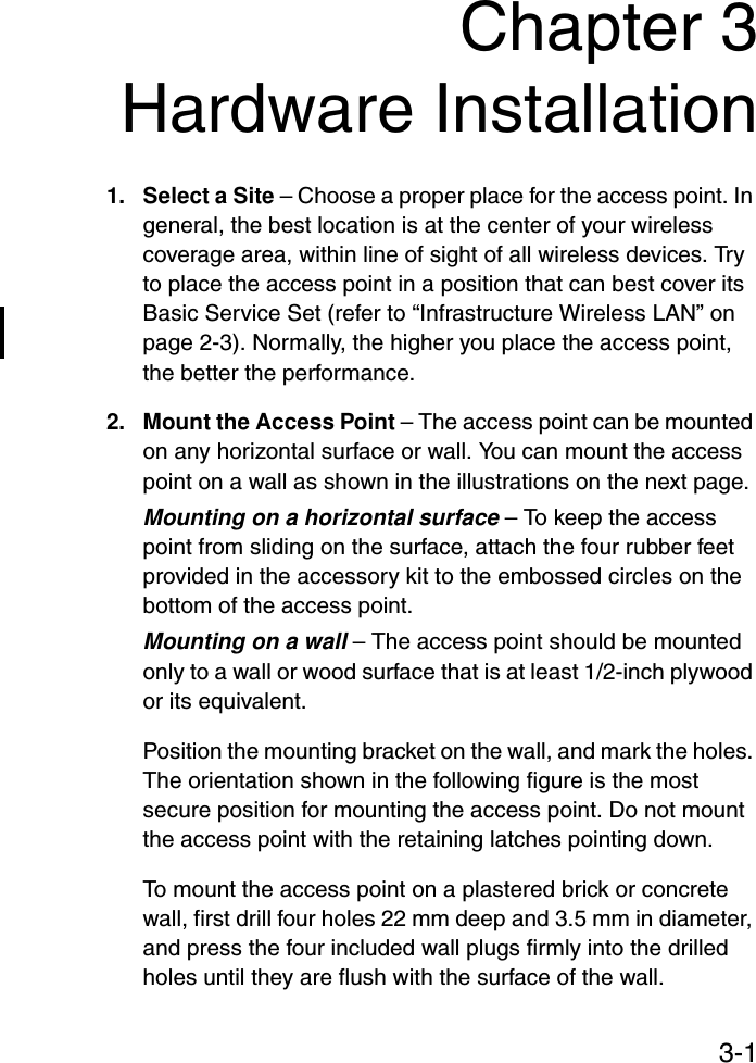
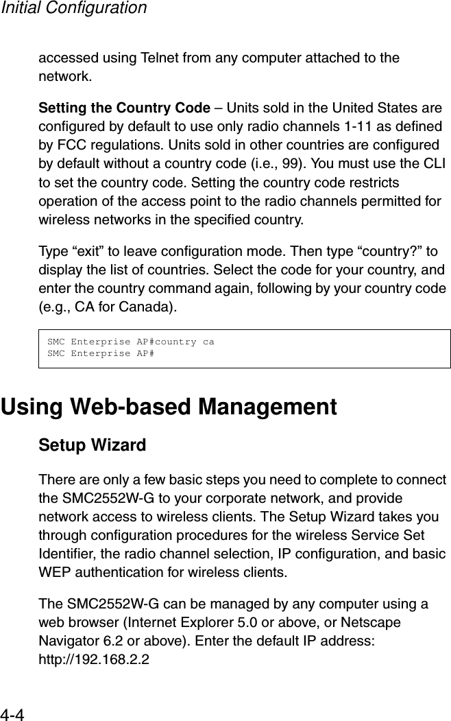
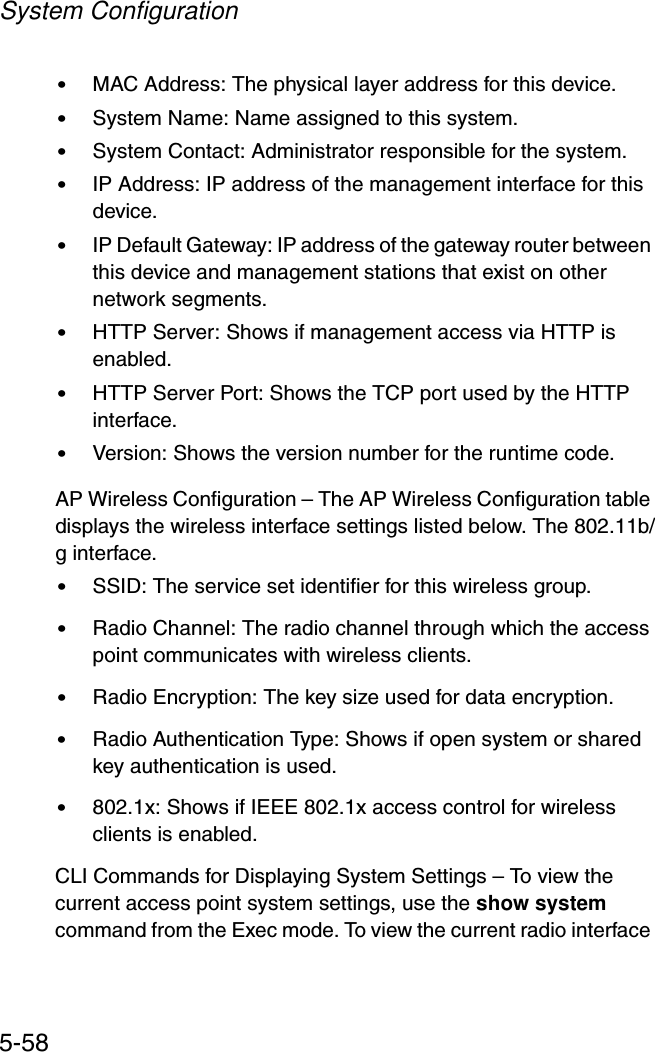
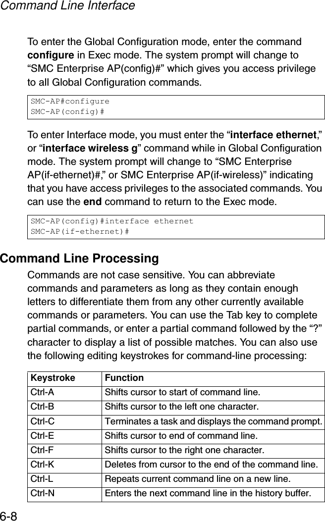
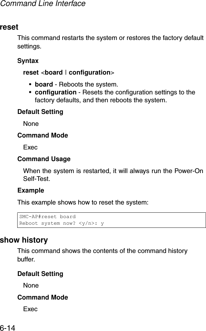
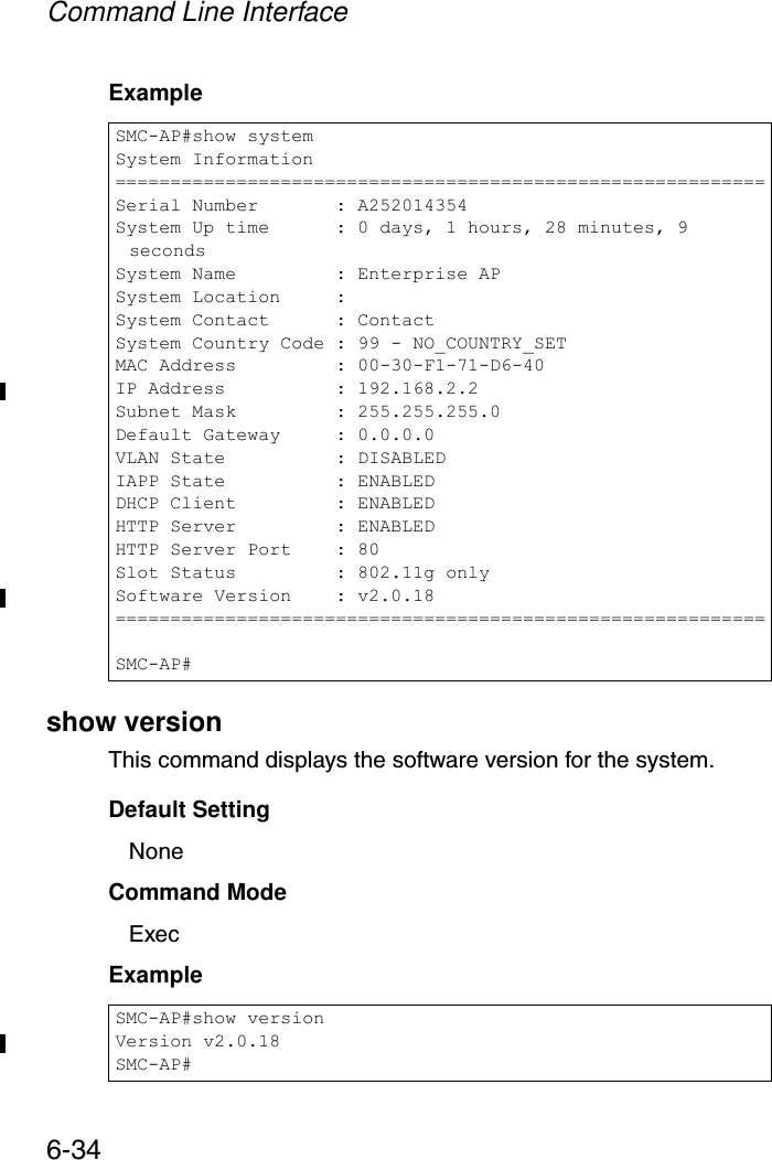
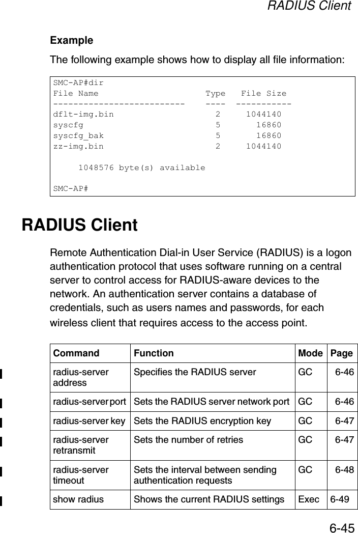
![Advanced Configuration5-31CLI Commands for Downloading Software from a TFTP Server – Use the copy tftp file command from the Exec mode and then specify the file type, name, and IP address of the TFTP server. When the download is complete, the dir command can be used to check that the new file is present in the access point file system. To run the new software, use the reset board command to reboot the access point.SMC-AP#copy tftp file 6-421. Application image2. Config file3. Boot block imageSelect the type of download<1,2,3>: [1]:1TFTP Source file name:smc-img.binTFTP Server IP:192.168.1.19SMC-AP#dir 6-44File Name Type File Size-------------------------- ---- -----------dflt-img.bin 2 1319939smc-img.bin 2 1629577syscfg 5 17776syscfg_bak 5 17776 262144 byte(s) availableSMC-AP#reset board 6-14Reboot system now? <y/n>: y](https://usermanual.wiki/Accton-Technology/SMC2552WG/User-Guide-396480-Page-79.png)

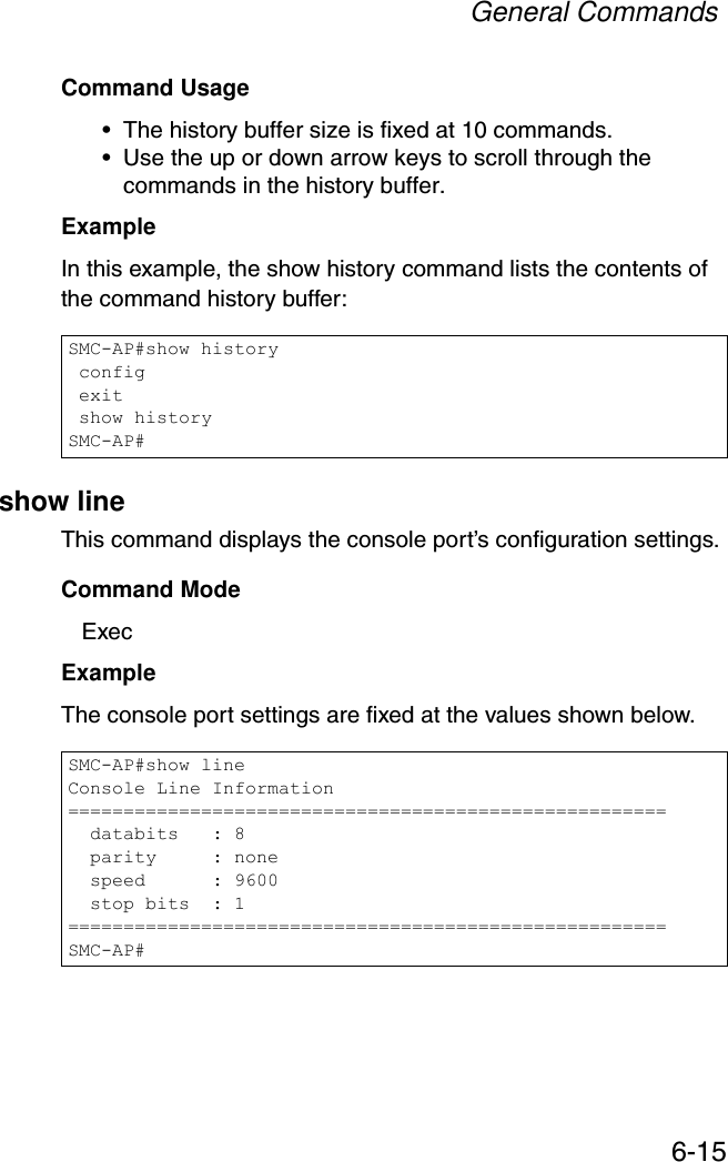
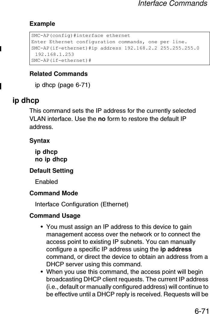
![Entering Commands6-7Exec CommandsWhen you open a new console session on access point, the system enters Exec command mode. Only a limited number of the commands are available in this mode. You can access all other commands only from the configuration mode. To access Exec mode, open a new console session with the user name “admin.” The command prompt displays as “SMC Enterprise AP#” for Exec mode. Configuration CommandsConfiguration commands are used to modify access point settings. These commands modify the running configuration and are saved in memory. The configuration commands are organized into three different modes:•Global Configuration - These commands modify the system level configuration, and include commands such as username and password. •Interface-Ethernet Configuration - These commands modify the Ethernet port configuration, and include command such as dns and ip.•Interface-Wireless Configuration - These commands modify the wireless port configuration, and include command such as ssid and authentication.Username: adminPassword: [system login password]SMC-AP#](https://usermanual.wiki/Accton-Technology/SMC2552WG/User-Guide-396480-Page-119.png)

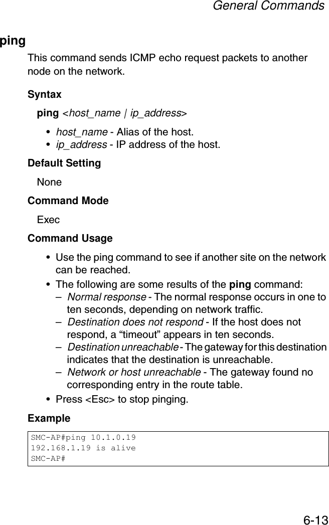
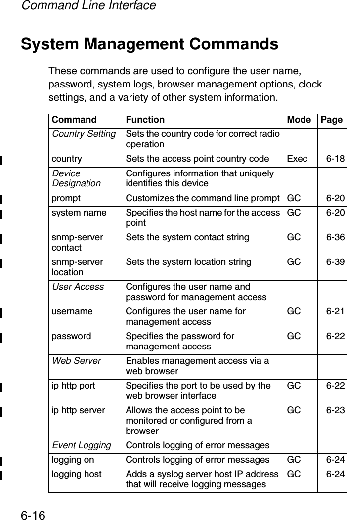

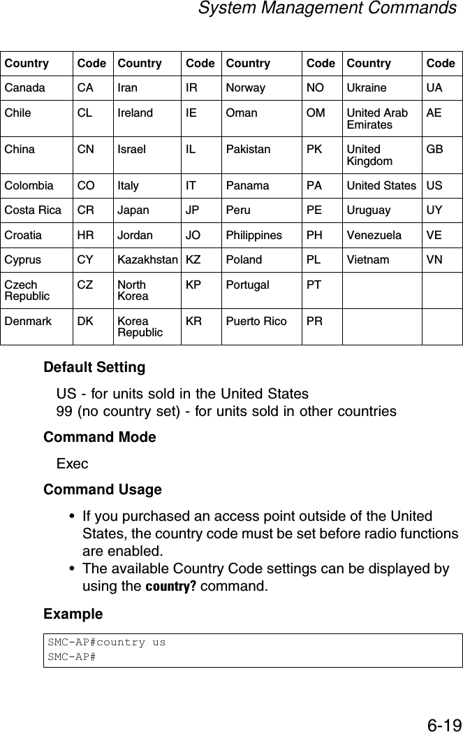
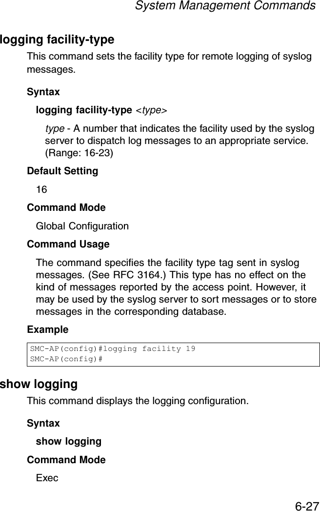
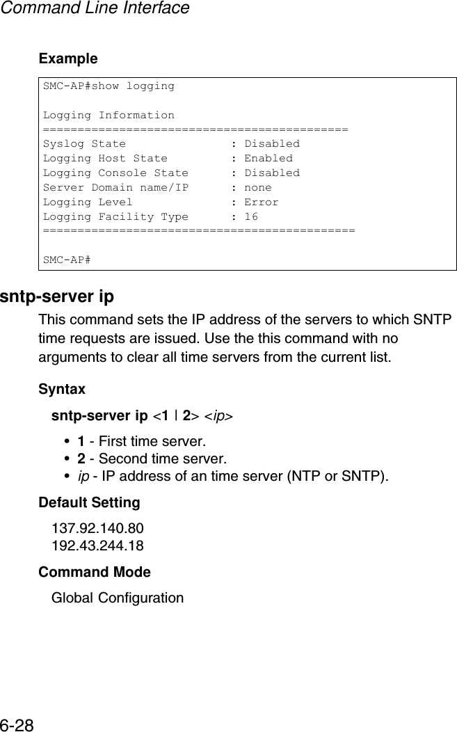
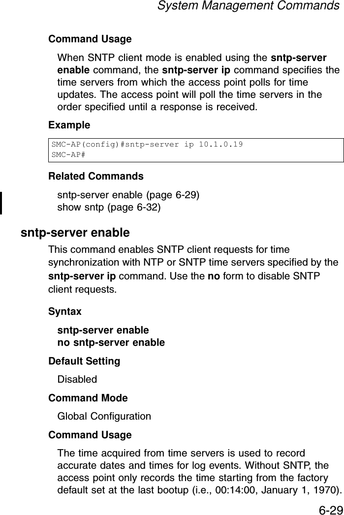
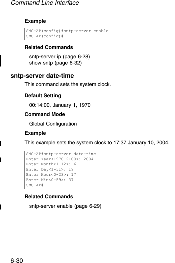
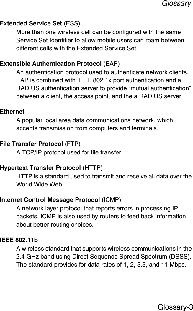
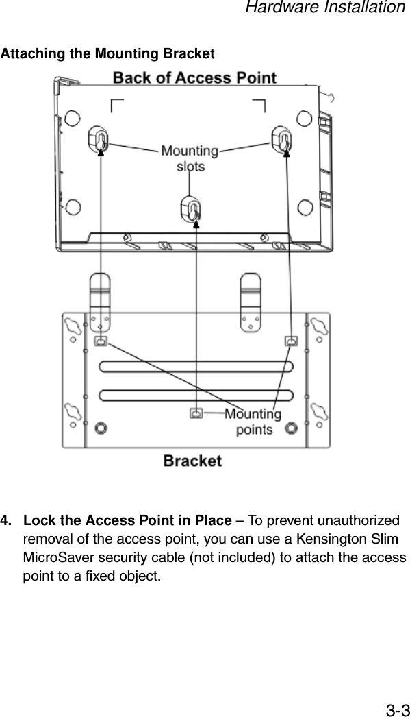
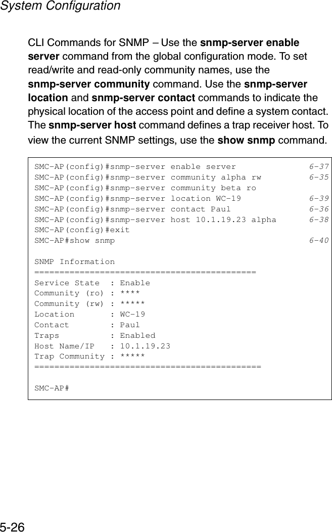
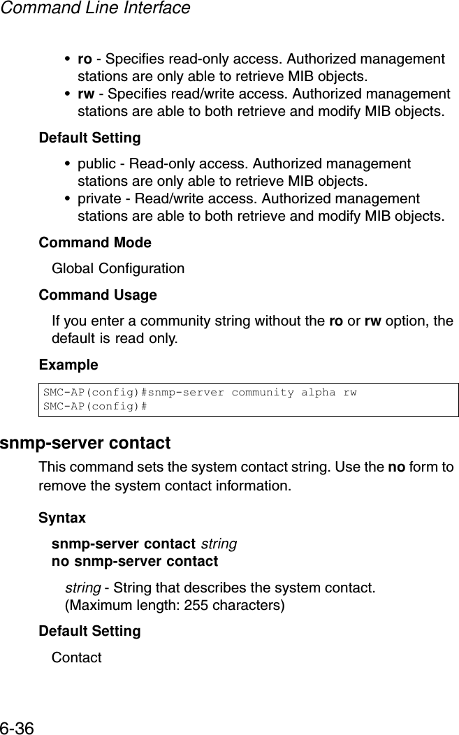
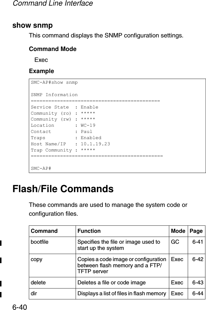
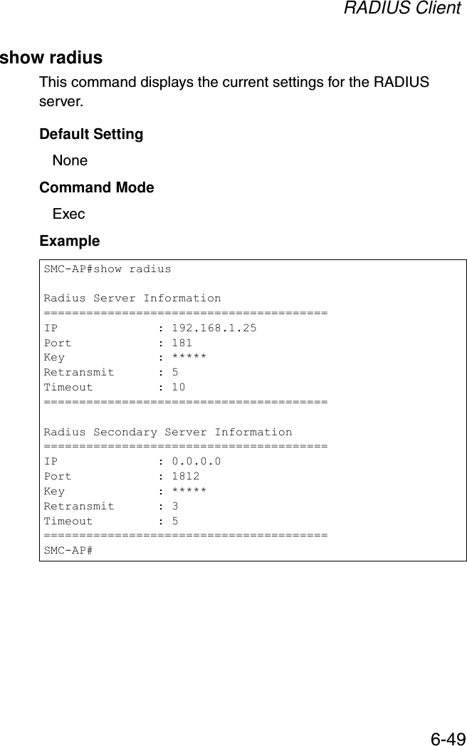
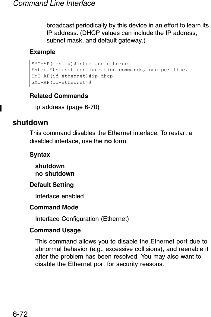
![SNMP Commands6-35SNMP CommandsControls access to this access point from management stations using the Simple Network Management Protocol (SNMP), as well as the hosts that will receive trap messages.snmp-server communityThis command defines the community access string for the Simple Network Management Protocol. Use the no form to remove the specified community string.Syntaxsnmp-server community string [ro | rw]no snmp-server community string•string - Community string that acts like a password and permits access to the SNMP protocol. (Maximum length: 23 characters, case sensitive)Command Function Mode Pagesnmp-server community Sets up the community access string to permit access to SNMP commands GC 6-35snmp-server contact Sets the system contact string GC 6-36snmp-server enable server Enables SNMP service and traps GC 6-37snmp-server host Specifies the recipient of an SNMP notification operation GC 6-38snmp-server location Sets the system location string GC 6-39show snmp Displays the status of SNMP communications Exec 6-40](https://usermanual.wiki/Accton-Technology/SMC2552WG/User-Guide-396480-Page-147.png)
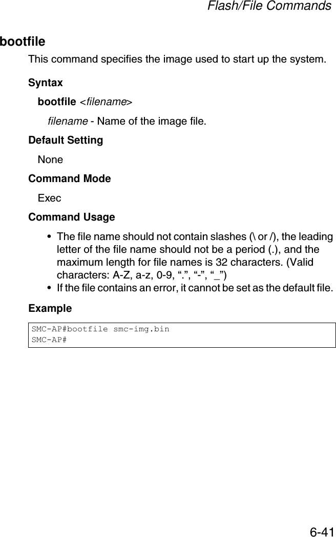
![Flash/File Commands6-43server is 255 characters or 32 characters for files on the access point. (Valid characters: A-Z, a-z, 0-9, “.”, “-”, “_”)• Due to the size limit of the flash memory, the access point supports only two operation code files.• The system configuration file must be named “syscfg” in all copy commands.Example The following example shows how to upload the configuration settings to a file on the TFTP server:The following example shows how to download a configuration file: deleteThis command deletes a file or image.Syntaxdelete filenamefilename - Name of the configuration file or image name.Default Setting NoneSMC-AP#copy config tftpTFTP Source file name:syscfgTFTP Server IP:192.168.1.19SMC-AP#SMC-AP#copy tftp file1. Application image2. Config file3. Boot block imageSelect the type of download<1,2,3>: [1]:2TFTP Source file name:syscfgTFTP Server IP:192.168.1.19SMC-AP#](https://usermanual.wiki/Accton-Technology/SMC2552WG/User-Guide-396480-Page-155.png)
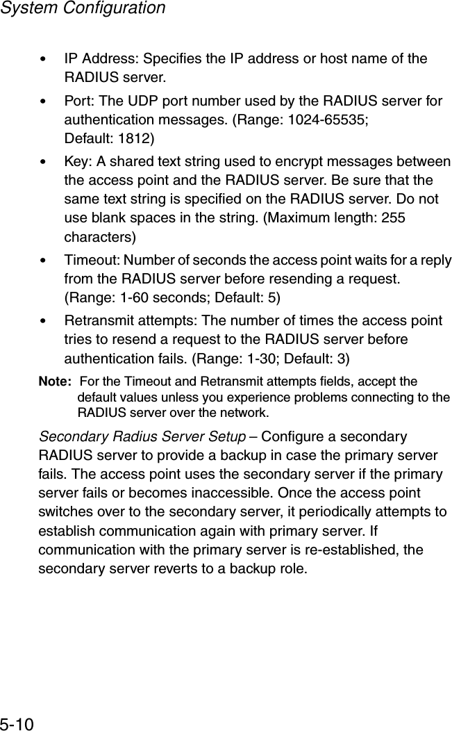
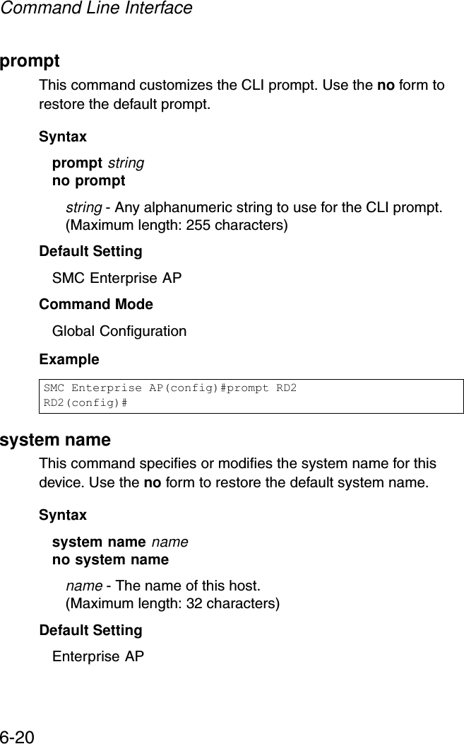
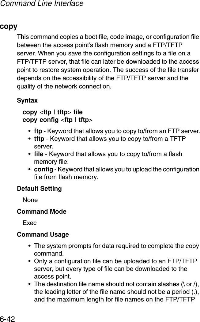
![Command Line Interface6-46radius-server addressThis command specifies the primary and secondary RADIUS servers. Syntaxradius-server address [secondary] <host_ip_address | host_name>•secondary - Secondary server.•host_ip_address - IP address of server.•host_name - Host name of server. (Range: 1-20 characters)Default Setting NoneCommand Mode Global ConfigurationExample radius-server portThis command sets the RADIUS server network port. Syntaxradius-server [secondary] port <port_number>•secondary - Secondary server.•port_number - RADIUS server UDP port used for authentication messages. (Range: 1024-65535)Default Setting 1812Command Mode Global ConfigurationSMC-AP(config)#radius-server address 192.168.1.25SMC-AP(config)#](https://usermanual.wiki/Accton-Technology/SMC2552WG/User-Guide-396480-Page-158.png)
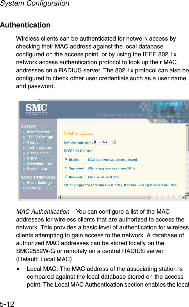
![RADIUS Client6-47Example radius-server keyThis command sets the RADIUS encryption key. Syntax radius-server [secondary] key <key_string>•secondary - Secondary server.•key_string - Encryption key used to authenticate logon access for client. Do not use blank spaces in the string. (Maximum length: 20 characters)Default Setting DEFAULTCommand Mode Global ConfigurationExample radius-server retransmitThis command sets the number of retries. Syntaxradius-server [secondary] retransmit number_of_retries•secondary - Secondary server.•number_of_retries - Number of times the access point will try to authenticate logon access via the RADIUS server. (Range: 1 - 30)SMC-AP(config)#radius-server port 181SMC-AP(config)#SMC-AP(config)#radius-server key greenSMC-AP(config)#](https://usermanual.wiki/Accton-Technology/SMC2552WG/User-Guide-396480-Page-159.png)
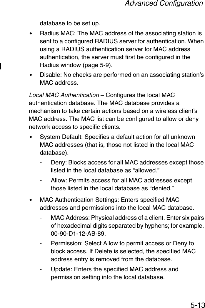
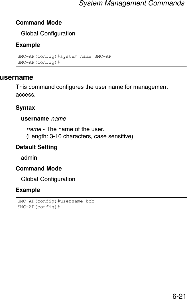
![Command Line Interface6-48Default Setting 3Command Mode Global ConfigurationExample radius-server timeoutThis command sets the interval between transmitting authentication requests to the RADIUS server. Syntax radius-server [secondary] timeout number_of_seconds•secondary - Secondary server.•number_of_seconds - Number of seconds the access point waits for a reply before resending a request. (Range: 1-60)Default Setting 5Command Mode Global ConfigurationExample SMC-AP(config)#radius-server retransmit 5SMC-AP(config)#SMC-AP(config)#radius-server timeout 10SMC-AP(config)#](https://usermanual.wiki/Accton-Technology/SMC2552WG/User-Guide-396480-Page-160.png)
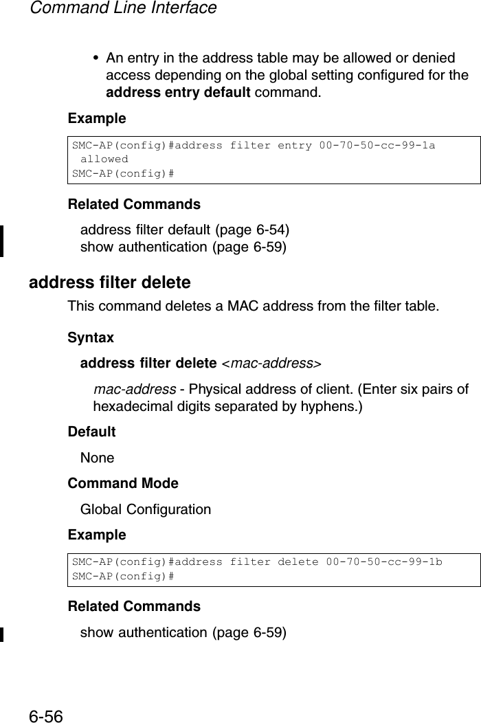
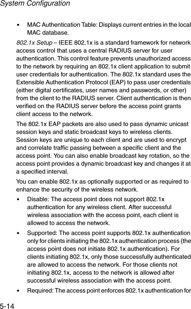
![802.1x Port Authentication6-57mac-authentication serverThis command sets address filtering to be performed with local or remote options. Use the no form to disable MAC address authentication.Syntaxmac-authentication server [local | remote]•local - Authenticate the MAC address of wireless clients with the local authentication database during 802.11 association.•remote - Authenticate the MAC address of wireless clients with the RADIUS server during 802.1x authentication.DefaultlocalCommand ModeGlobal ConfigurationExampleRelated Commandsaddress filter entry (page 6-55)radius-server address (page 6-46)show authentication (page 6-59)SMC-AP(config)#mac-authentication server remoteSMC-AP(config)#](https://usermanual.wiki/Accton-Technology/SMC2552WG/User-Guide-396480-Page-169.png)
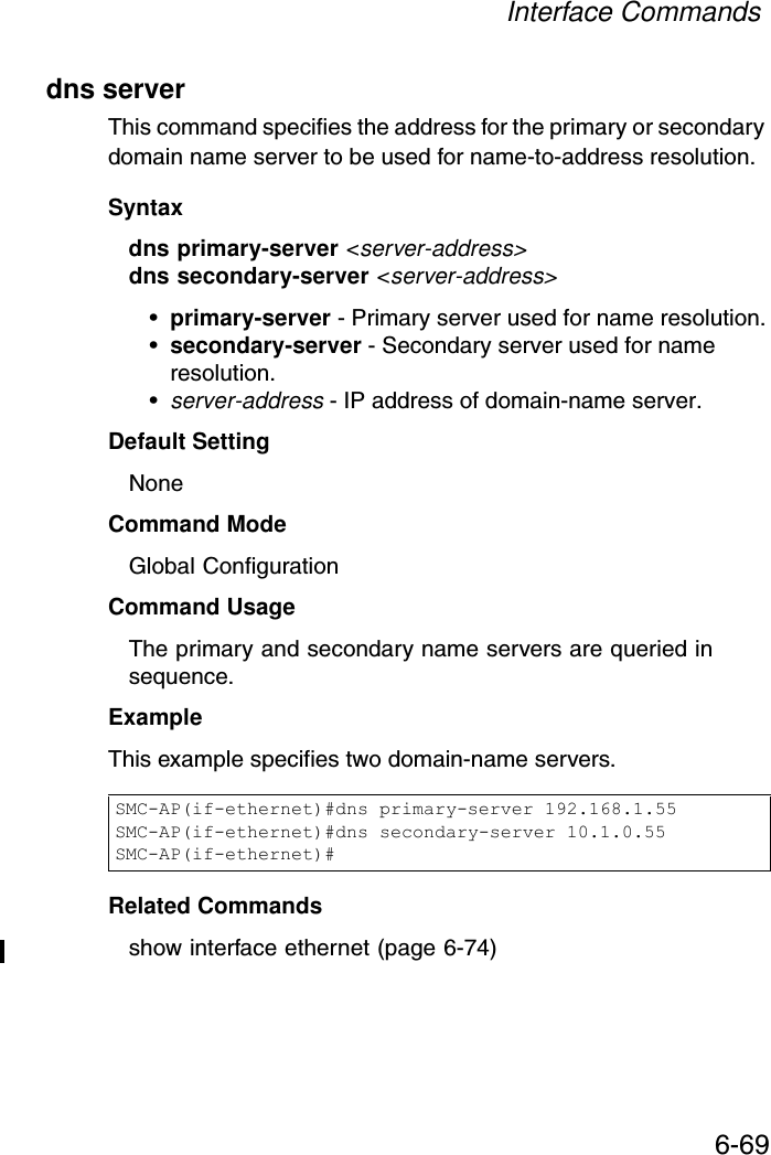
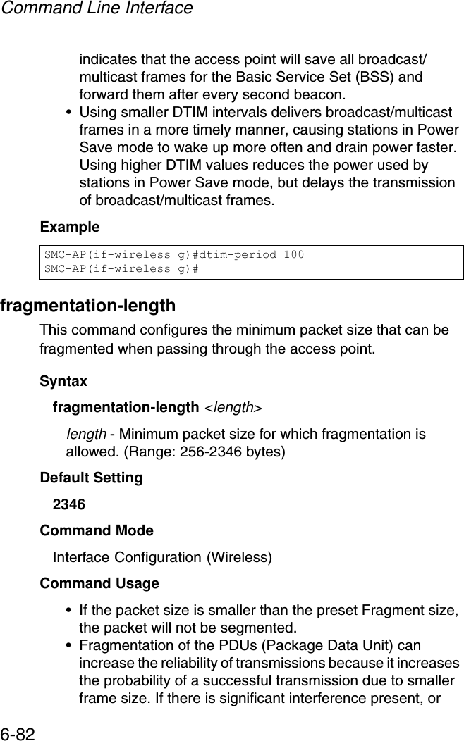
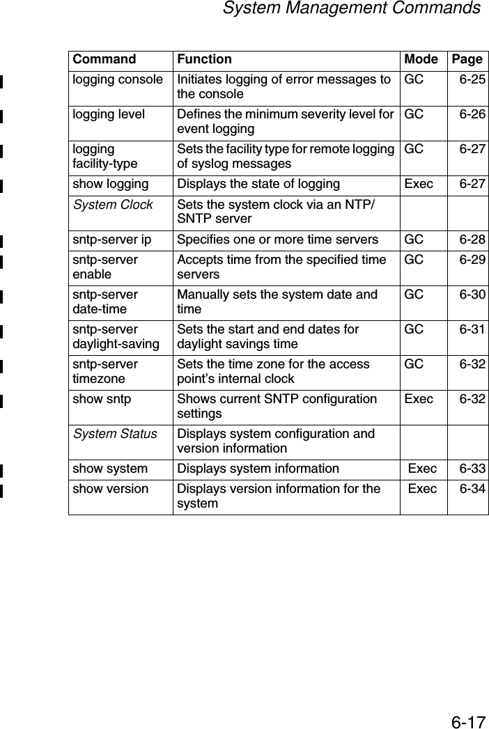
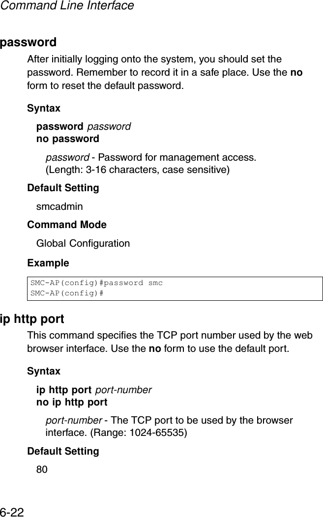
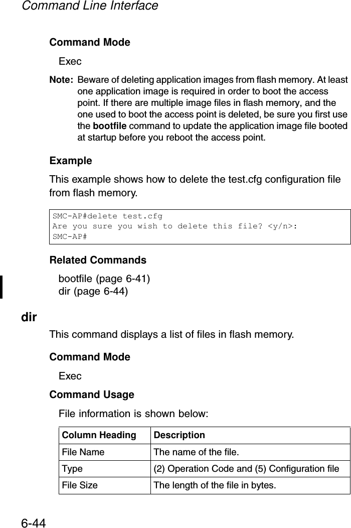
![Command Line Interface6-74show interface ethernetThis command displays the status for the Ethernet interface.Syntaxshow interface [ethernet]Default Setting Ethernet interfaceCommand Mode ExecExample radio-mode This command sets the working mode for the wireless interface.Syntaxradio-mode <b | g | b+g>• b - b-only mode: Both 802.11b and 802.11g clients can communicate with the access point, but 802.11g clients can only transfer data at 802.11b standard rates (up to 11 Mbps).SMC-AP#show interface ethernetEthernet Interface Information========================================IP Address : 192.168.2.2Subnet Mask : 255.255.255.0Default Gateway : 192.168.1.253Primary DNS : 192.168.1.55Secondary DNS : 10.1.0.55Speed-duplex : 100Base-TX Half DuplexAdmin status : UpOperational status : Up========================================SMC-AP#](https://usermanual.wiki/Accton-Technology/SMC2552WG/User-Guide-396480-Page-186.png)