Accton Technology SMC7901WBRA1 WIRELESS ADSL 2/2+ ROUTER User Manual
Accton Technology Corp WIRELESS ADSL 2/2+ ROUTER Users Manual
UserManual.wiki
>
Accton Technology
>
SMC7901WBRA1 User Manual
Users Manual
Navigation menu
Upload a User Manual
Namespaces
Wiki Guide
HTML
PDF
Info
Views
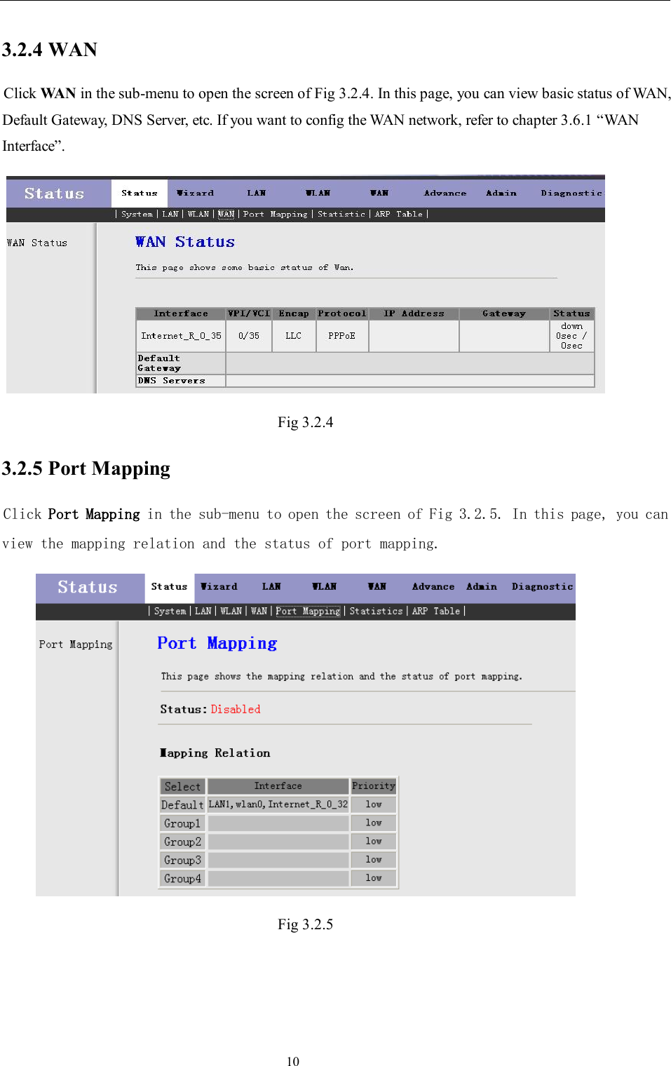
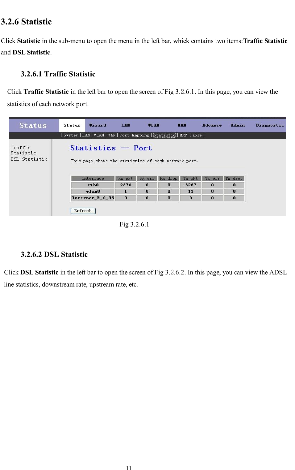
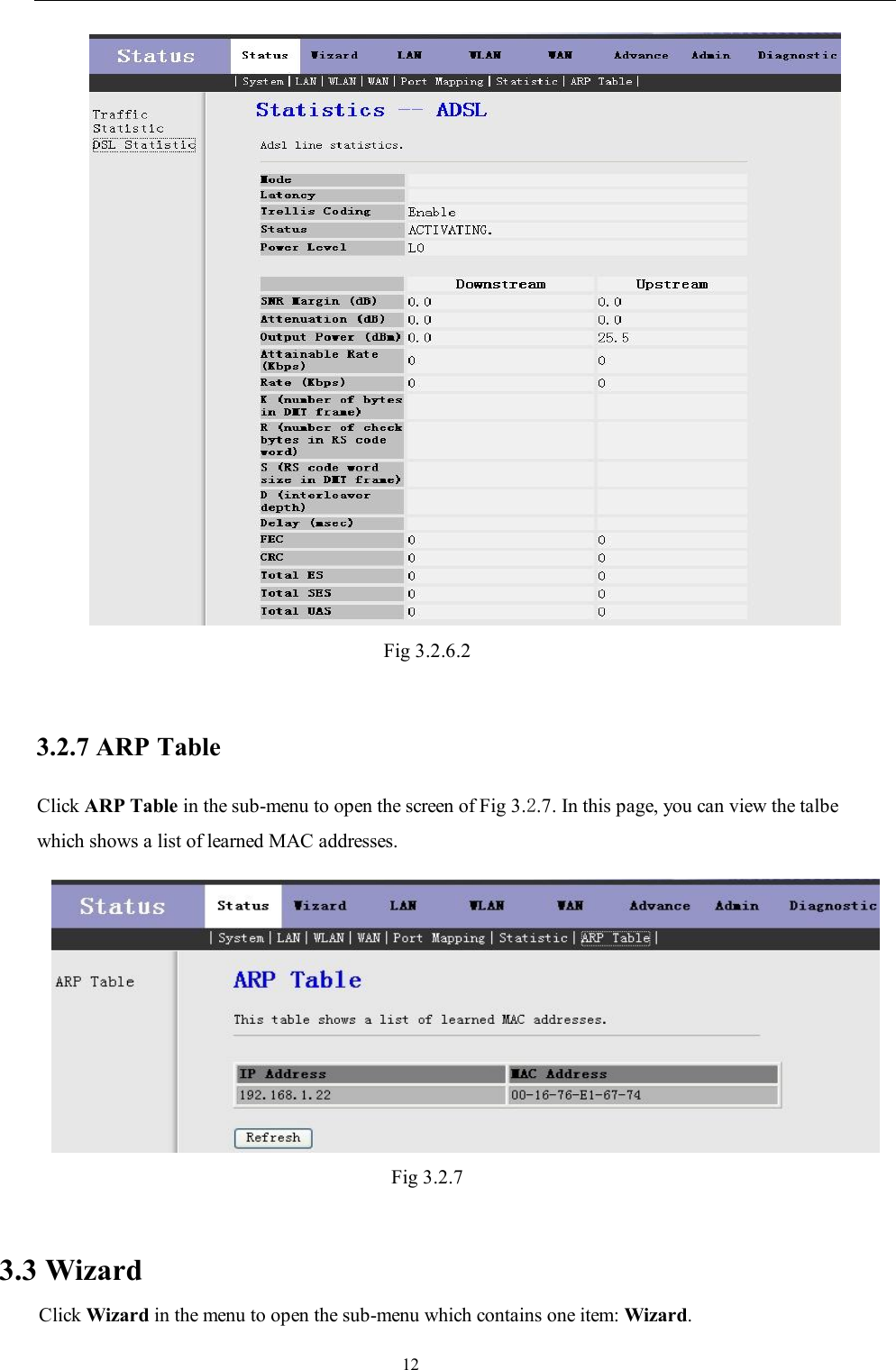
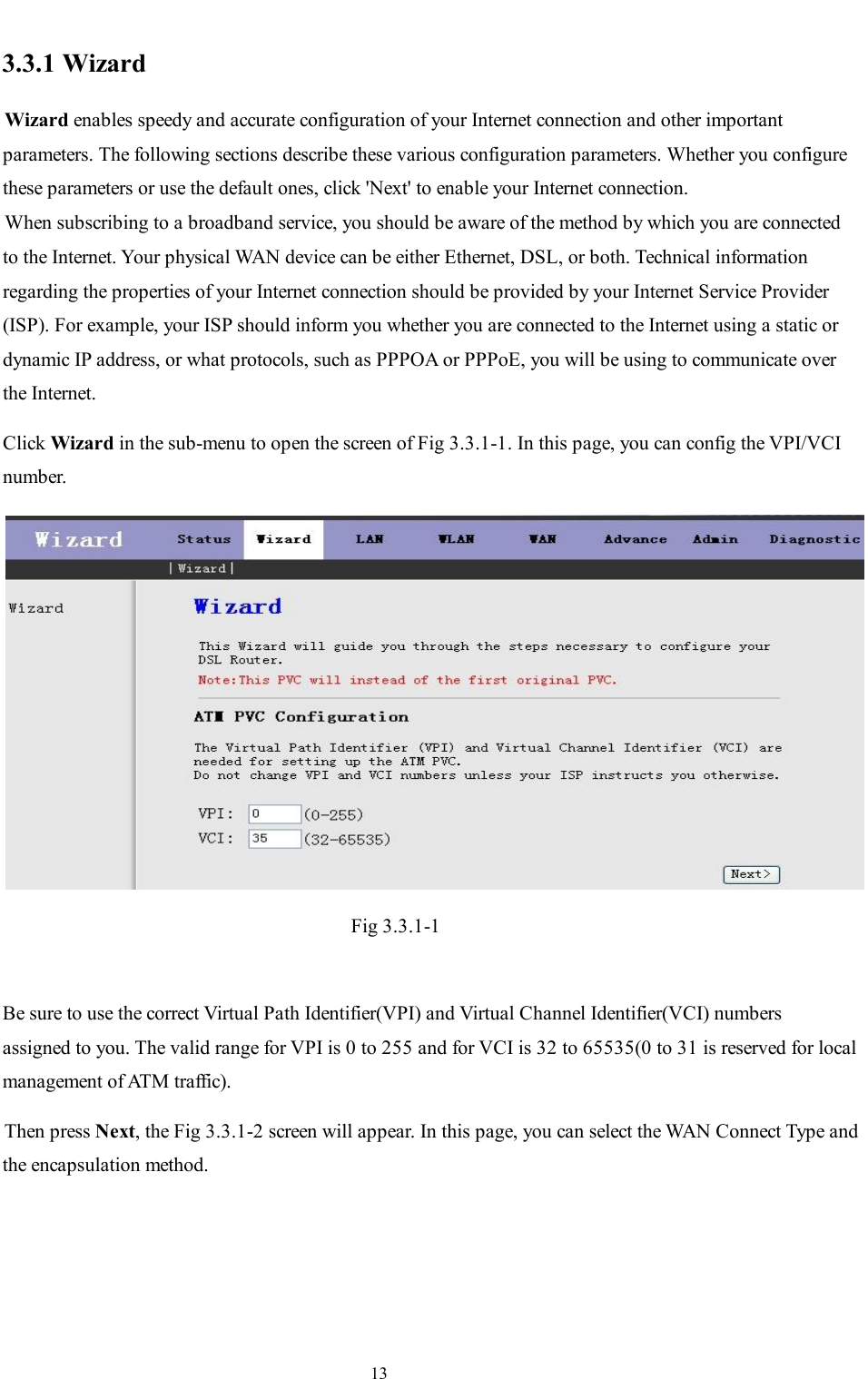
User Manual
Discussion / Help
Navigation