Accton Technology SMC7901WR ADSL/ADSL2/ADSL2+ 1-Port Wireless Router User Manual User Guide
Accton Technology Corp ADSL/ADSL2/ADSL2+ 1-Port Wireless Router User Guide
UserManual.wiki
>
Accton Technology
>
SMC7901WR User Manual
Manual
Navigation menu
Upload a User Manual
Namespaces
Wiki Guide
HTML
PDF
Info
Views
User Manual
Discussion / Help
Navigation
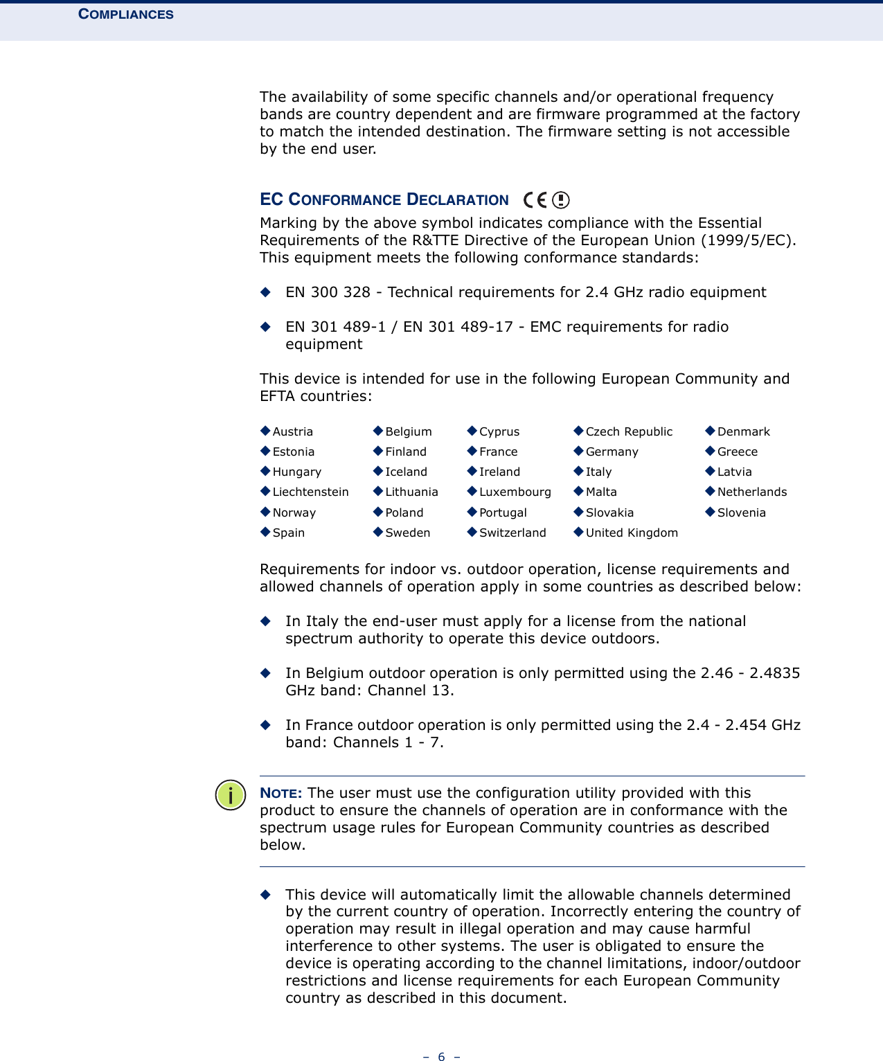
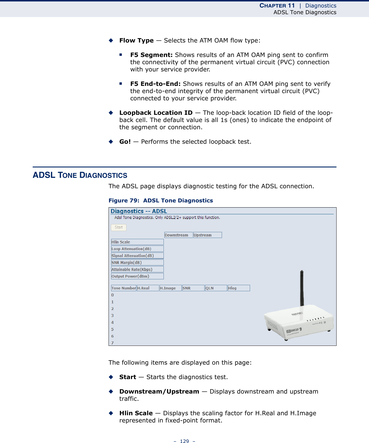
![COMPLIANCES– 8 –CUSTOMER INFORMATION◆This equipment complies with Part 68 of the FCC rules and the requirements adopted by the ACTA. On bottom of this equipment is a label that contains, among other information, a product identifier of [INSERT LABEL]. If requested, this number must be provided to the telephone company.◆If this equipment SMC7901BRA2 B1 causes harm to the telephone network, the telephone company will notify you in advance that temporary discontinuance of service may be required. But if advance notice isn’t practical, the telephone company will notify the customer as soon as possible. Also you will be advised of your right to file a complaint with the FCC if you believe it is necessary.◆The telephone company may make changes in its facilities, equipment, operations or procedures that could affect the operation of the equipment. If this happens, the telephone company will provide advance notice in order for you to make necessary modification to maintain uninterrupted service.◆If you experience trouble with this equipment, you disconnect it from the network until the problem has been corrected or until you are sure that the equipment is not malfunctioning.◆Please follow instructions for repairing if any (e.g. battery replacement section); otherwise do not alternate or repair any parts of device except specified.◆Connection to party line service is subject to state tariffs. Contact the state public utility commission, public service commission or corporation commission for information.◆If the telephone company requests information on what equipment is connected to their lines, inform them of:◆The telephone number that this unit is connected to,◆The ringer equivalence number [ ]MalteseMaltiHawnhekk, SMC, jiddikjara li dan Radio LAN device jikkonforma mal-ħtiġijiet essenzjali u ma provvedimenti oħrajn relevanti li hemm fid-Dirrettiva 1999/5/EC.SpanishEspañolPor medio de la presente SMC declara que el Radio LAN device cumple con los requisitos esenciales y cualesquiera otras disposiciones aplicables o exigibles de la Directiva 1999/5/CEPolishPolskiNiniejszym SMC oświadcza, że Radio LAN device jest zgodny z zasadniczymi wymogami oraz pozostałymi stosownymi postanowieniami Dyrektywy 1999/5/EC.PortuguesePortuguêsSMC declara que este Radio LAN device está conforme com os requisitos essenciais e outras disposições da Directiva 1999/5/CE.SlovakSlovenskySMC týmto vyhlasuje, že Radio LAN device spĺňa základné požiadavky a všetky príslušné ustanovenia Smernice 1999/5/ES.SlovenianSlovenskoSMC izjavlja, da je ta radio LAN device v skladu z bistvenimi zahtevami in ostalimi relevantnimi določili direktive 1999/5/ES.](https://usermanual.wiki/Accton-Technology/SMC7901WR/User-Guide-1145318-Page-8.png)
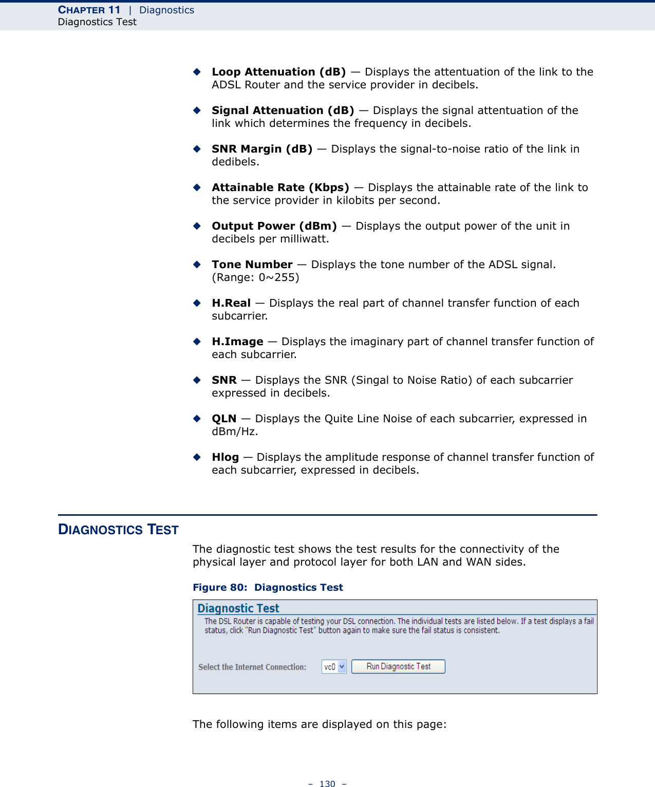
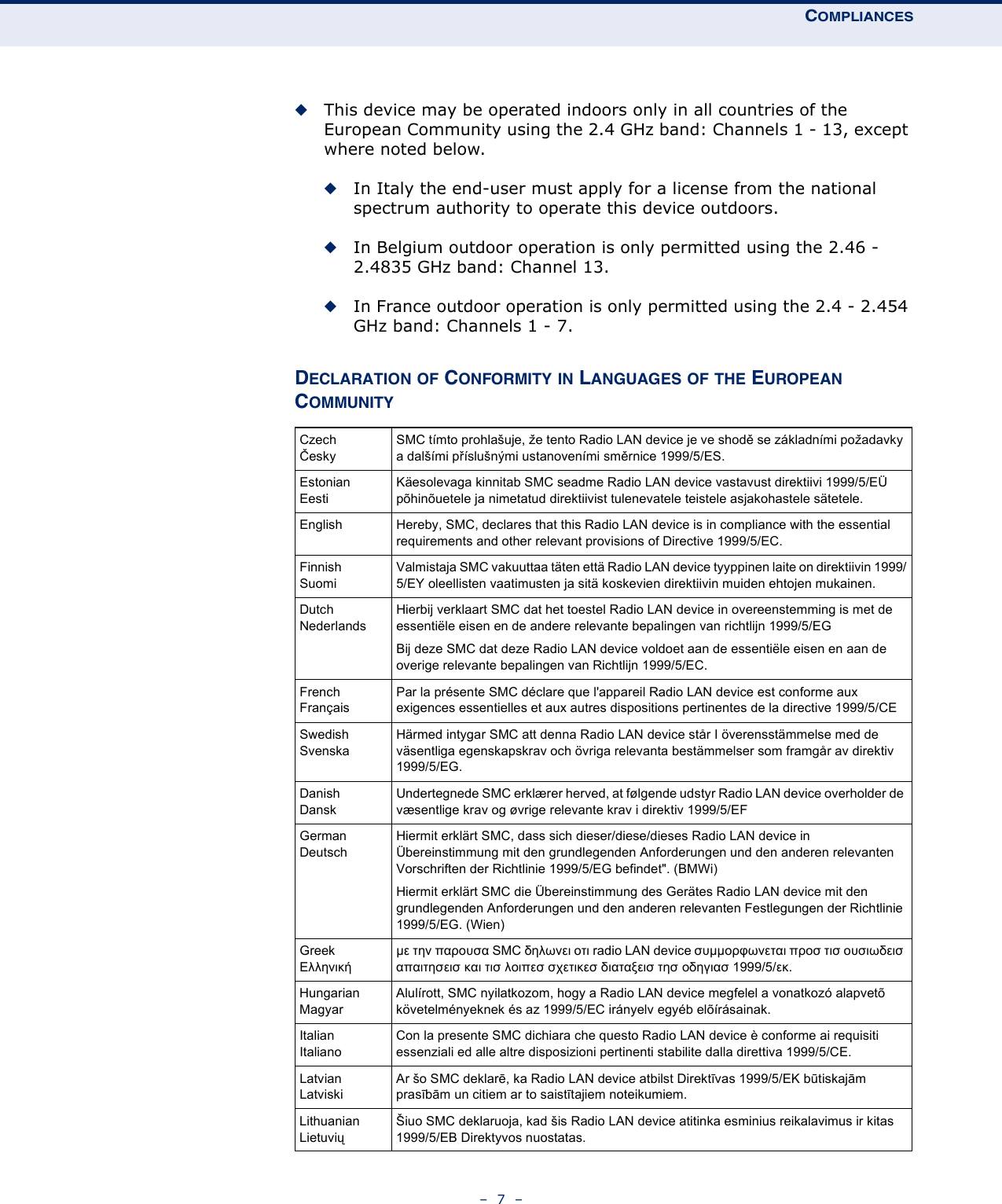
![COMPLIANCES– 9 –◆The USOC jack required [ ], and◆The FCC Registration NumberItem (b) and (d) are indicated on the label. The ringer equivalence number (REN) is used to determine how many devices can be connected to your telephone line. In most areas, the sum of the RENs of all devices on any one line should not exceed five (5.0). If too many devices are attached, they may not ring properly.◆If your home has specially wired alarm equipment connected to the telephone line, ensure the installation of this equipment does not disable alarm equipment, consult your telephone company or a qualified installer.SERVICE REQUIREMENTSIn the event of equipment malfunction, all repairs should be performed by our Company or an authorized agent. It is the responsibility of users requiring service to report the need for service to our Company or to one of our authorized agents. Service can be facilitated through our office at:SMC Networks North America 20 MasonIrvine, CA 92618USA](https://usermanual.wiki/Accton-Technology/SMC7901WR/User-Guide-1145318-Page-9.png)