Accton Technology VG2211I Personal Mobile Gateway User Manual VG2211I 38
Accton Technology Corp Personal Mobile Gateway VG2211I 38
Users Manual
WA6102-ZZ
VG007
Personal Mobile Gateway
Installation Guide

Installation Guide
Guide
Personal Mobile Gateway
VoIP Internet Gateway
with IEEE 802.11b/g Wireless Access Point,
IEEE 802.11b/g Wireless Client,
IEEE 802.11b/g Wireless Repeater,
and PSTN Telephony Functions

VG007
E122005-R01
149100032900E
Compliances
Federal Communication Commission Interference Statement
This device complies with Part 15 of the FCC Rules. Operation is subject to the following two
conditions: (1) This device may not cause harmful interference, and (2) this device must accept any
interference received, including interference that may cause undesired operation.
This equipment has been tested and found to comply with the limits for a Class B digital device,
pursuant to Part 15 of the FCC Rules. These limits are designed to provide reasonable protection
against harmful interference in a residential installation. This equipment generates, uses and can
radiate radio frequency energy and, if not installed and used in accordance with the instructions,
may cause harmful interference to radio communications. However, there is no guarantee that
interference will not occur in a particular installation. If this equipment does cause harmful
interference to radio or television reception, which can be determined by turning the equipment off
and on, the user is encouraged to try to correct the interference by one of the following measures:
Reorient or relocate the receiving antenna
Increase the separation between the equipment and receiver
Connect the equipment into an outlet on a circuit different from that to which the receiver is
connected
Consult the dealer or an experienced radio/TV technician for help
FCC Caution: Any changes or modifications not expressly approved by the party responsible for
compliance could void the user's authority to operate this equipment.
IMPORTANT NOTE:FCC Radiation Exposure Statement
This equipment complies with FCC radiation exposure limits set forth for an uncontrolled
environment. This equipment should be installed and operated with a minimum distance of 20
centimeters (8 inches) between the radiator and your body. This transmitter must not be co-located
or operating in conjunction with any other antenna or transmitter.
The antenna(s) used for this transmitter must not be co-located or operating in conjunction with any
other antenna or transmitter.
Industry Canada -Class B
This digital apparatus does not exceed the Class B limits for radio noise emissions from digital
apparatus as set out in the interference-causing equipment standard entitled “Digital Apparatus,”
ICES-003 of Industry Canada.
Cet appareil numérique respecte les limites de bruits radioélectriques applicables aux appareils
numériques de Classe B prescrites dans la norme sur le matérial brouilleur: “Appareils
Numériques,” NMB-003 édictée par l’Industrie.

ii
EC Conformance Declaration
Marking by the above symbol indicates compliance with the Essential Requirements of
the R&TTE Directive of the European Union (1999/5/EC). This equipment meets the
following conformance standards:
• EN 60950 (IEC 60950) - Product Safety
• EN 300 328 - Technical requirements for 2.4 GHz radio equipment
• EN 301 489-1, EN 301 489-17 - EMC requirements for radio equipment
This device is intended for use in the following European Community countries:
Requirements for indoor vs. outdoor operation, license requirements and allowed
channels of operation apply in some countries as described below:
• In Italy the end-user must apply for a license from the national spectrum authority to
operate this device outdoors.
• In Belgium outdoor operation is only permitted using the 2.46 - 2.4835 GHz band:
Channel 13.
• In France outdoor operation is only permitted using the 2.4 - 2.454 GHz band: Channels
1 - 7.
• Austria • Belgium • Denmark
• Finland • France • Germany
• Italy • Luxembourg • Netherlands
• Norway • Spain • Sweden
• Switzerland • United Kingdom • Portugal
• Greece • Ireland • Iceland

iii
Contents
Chapter 1: Introduction 1-1
Package Checklist 1-1
Hardware Description 1-2
Component Description 1-3
Chapter 2: Connecting the Personal Mobile Gateway 2-1
Internet Gateway 2-1
Wireless Client 2-2
Wireless Access Point 2-3
Wireless Repeater 2-5
VoIP Telephony Functions 2-7
Appendix A: Troubleshooting A-1
Diagnosing LED Indicators A-1
Appendix B: Cables and Pinouts B-1
Twisted-Pair Cable Assignments B-1
10/100BASE-TX Pin Assignments B-1
Straight-Through Wiring B-2
Crossover Wiring B-2
RJ-11 Ports B-3
Appendix C: Specifications C-1
Physical Specifications C-1
Wireless Specifications C-2
VoIP Specifications C-2
Compliances C-3

iv
Contents

1-1
Chapter 1: Introduction
The Personal Mobile Gateway is a compact multi-funtion network connection device.
The unit provides secure wired and wireless high-speed data and VoIP (Voice over
Internet Protocol) communications through an Internet connection.
The Personal Mobile Gateway functions in the following operating modes:
• Secure Internet Gateway
• IEEE 802.11b/g Wireless Access Point
• IEEE 802.11b/g Wireless Client
• IEEE 802.11b/g Wireless Repeater
The Personal Mobile Gateway’s capabilities make it ideal for business travelers or
home users. The device provides a secure Internet gateway function between a
cable/DSL modem connection and its wired LAN port and wireless clients. The
integrated VoIP ability offers voice communications over the Internet from a wired or
wireless connected PC, or by connecting a regular telephone set to its PHONE port.
It can function as an 802.11b/g Wi-Fi access point providing a service to wireless
clients. Or, it can function as a wireless client itself for PC connections to other Wi-Fi
networks. In its wireless repeater mode, the Personal Mobile Gateway can extend
the wireless range of other access points for greater flexibility when seeking a
comfortable working location.
In addition, the Personal Mobile Gateway can automatically select the operating
mode based on its port connections, or it can be fully configured through an
easy-to-use web-browser management interface.
Package Checklist
The Personal Mobile Gateway package includes:
• One Personal Mobile Gateway
• Two RJ-45 Category 5 network cables
• One RJ-11 telephone cable
• One Y-type USB power supply cable
• One AC power adapter with detachable plug
• Documentation CD (includes Installation Guide and Management Guide)
Inform your dealer if there are any incorrect, missing or damaged parts. If possible,
retain the carton, including the original packing materials. Use them again to repack
the product in case there is a need to return it.
Introduction
1-2
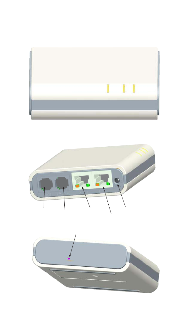
Hardware Description
Top Panel
Side Panels
Factory Default Reset Button
LAN Port
Power Socket
WAN Port
LINE Port
PHONE Port

Hardware Description
1-3
Component Description
WAN Port
The Personal Mobile Gateway’s WAN port is a standard RJ-45 Ethernet network
port. It is for connecting the gateway to an Internet connection device, such as an
ADSL or cable modem, or to a switch in an Ethernet network that provides Internet
access.
The WAN port can be attached directly to your cable/DSL modem using one of the
included Category 5 network cables. If you choose to use other, longer Category 5
network cables, be sure they conform to the specifications and pinouts provided in
Appendix B.
Note: The WAN port supports automatic MDI/MDI-X operation, which means you can
use the same “straight-through” network cable for connection to a cable/DSL
modem or Ethernet switch.
LAN Port
The Personal Mobile Gateway’s LAN port is a standard RJ-45 Ethernet network port
that connects directly to your PC. It can also be connected to an Ethernet switch or
hub to support more than one user.
The LAN port can be attached directly to your PC using one of the included
Category 5 network cables. If you choose to use other, longer Category 5 network
cables, be sure they conform to the specifications and pinouts provided in
Appendix B.
Note: The LAN port supports automatic MDI/MDI-X operation, which means you can
use the same “straight-through” network cable for connection to a PC or an
Ethernet switch.
PHONE Port
The Personal Mobile Gateway’s PHONE port is a standard RJ-11 telephone port
that connects directly to a standard (analog) telephone set. This allows a regular
telephone to be used for making VoIP calls over the Internet.
LINE Port
The Personal Mobile Gateway’s LINE port is a standard RJ-11 telephone port that
connects directly to a Public Switched Telephone Network (PSTN) jack.
Introduction
1-4
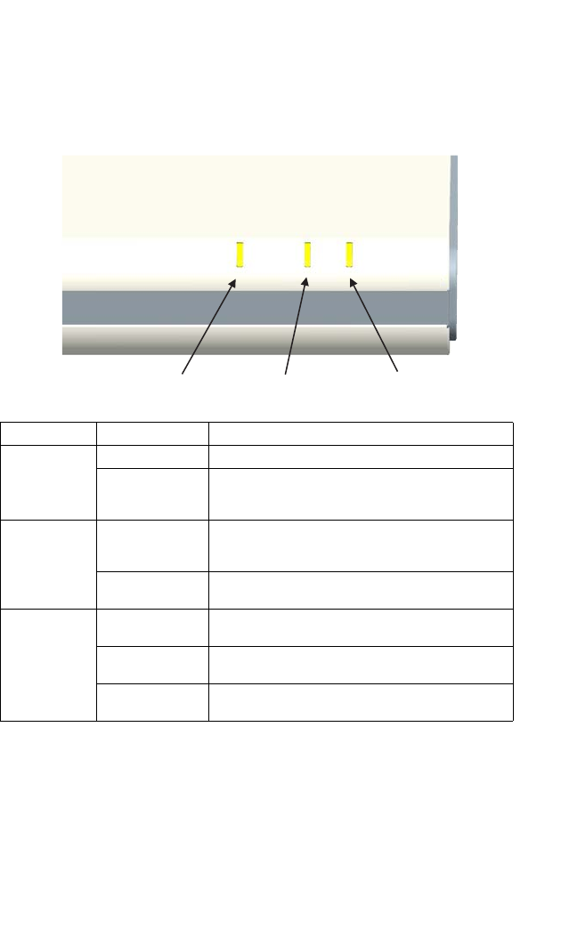
LED Indicators
The Personal Mobile Gateway includes three system status LED indicators and two
port LED indicators for each of the LAN and WAN ports, as described in the
following figures and tables.
LED Status Description
Power/Diag On Green Indicates that the system is working normally.
On Amber System running its power-on-self-test. If the LED remains
on amber for more than 20 seconds, it indicates system
errors.
Internet On Green Indicates the Personal Mobile Gateway has recieved an
IP address from a DHCP server and can connect to the
Internet.
Off The Personal Mobile Gateway has no configured IP
address to connect to the Internet.
Wireless Slow Flashing
Green Indicates a wireless association (connection) with a
strong radio signal.
Fast Flashing
Green Indicates a wireless association (connection) with a weak
radio signal.
Off Indicates no wireless association (connection) or no radio
signal
Power/Diag Internet Wireless
Hardware Description
1-5
Factory Default Reset Button
This button is used to reset the Personal Mobile Gateway to its factory default
configuration. If you press and hold down the button for 5 seconds or more, any
configuration changes you may have made are removed and the factory default
configuration is restored.
Power Connector
The Personal Mobile Gateway does not have a power switch. It is powered on when
connected to the AC power adapter, and the power adapter is connected to a power
source. The power adapter automatically adjusts to any voltage between 100-240
volts at 50 or 60 Hz. No voltage range settings are required.
The Personal Mobile Gateway can also be powered directly from a PC’s USB ports
using the included Y-type USB power cable. The Personal Mobile Gateway requires
two USB port connections to receive sufficient power.
Radio Antenna
The Personal Mobile Gateway includes an integrated internal antenna for wireless
comunications. No external connections or adjustments are required.
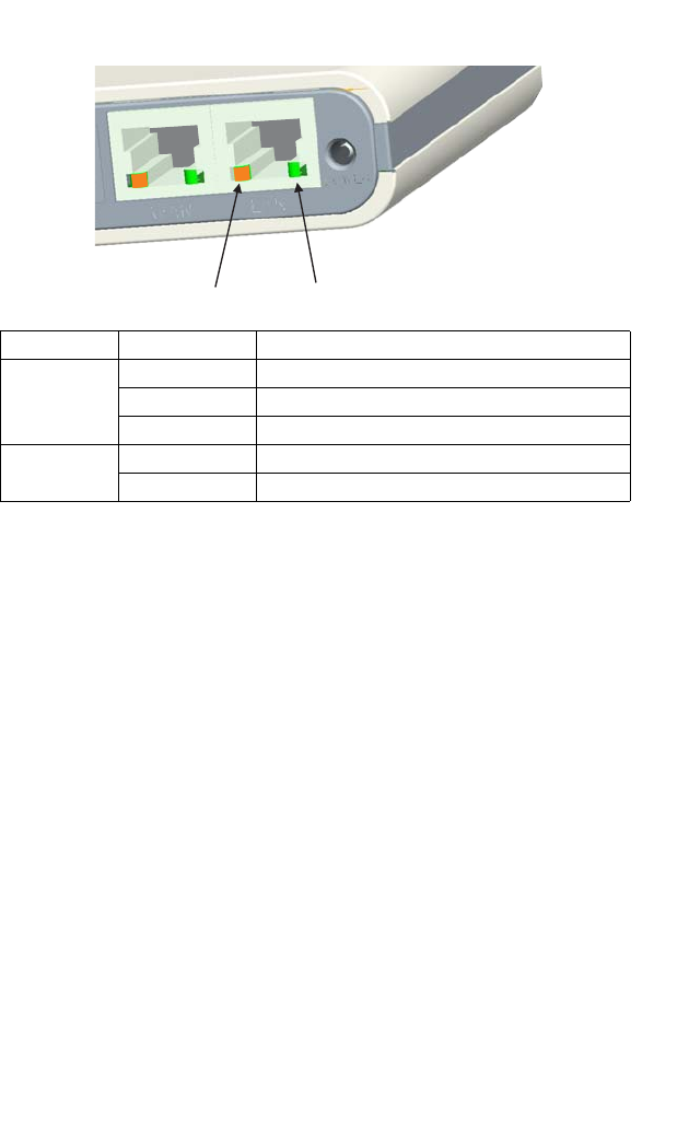
LED Status Description
Right
(Link/Activity) On Green Indicates a valid network link on the port.
Flashing Green Indicates network activity on a port link.
Off There is no valid network link on the port.
Left
(Speed) On Amber Indicates the port is operating at 100 Mbps.
Off Indicates the port is operating at 10 Mbps.
Link/Activity
Speed

Introduction
1-6
2-1
Chapter 2: Connecting the Personal
Mobile Gateway
In its default setting, the Personal Mobile Gateway’s operating mode is determined
by how it is connected. The Internet gateway and wireless client modes are
automatically implemented depending on the WAN port connection. The wireless
access point and wireless repeater modes, as well as VoIP functions, require
manual configuration using the Personal Mobile Gateway’s web management
interface.
The connections for each operating mode are described in the following sections.
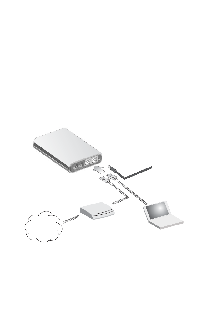
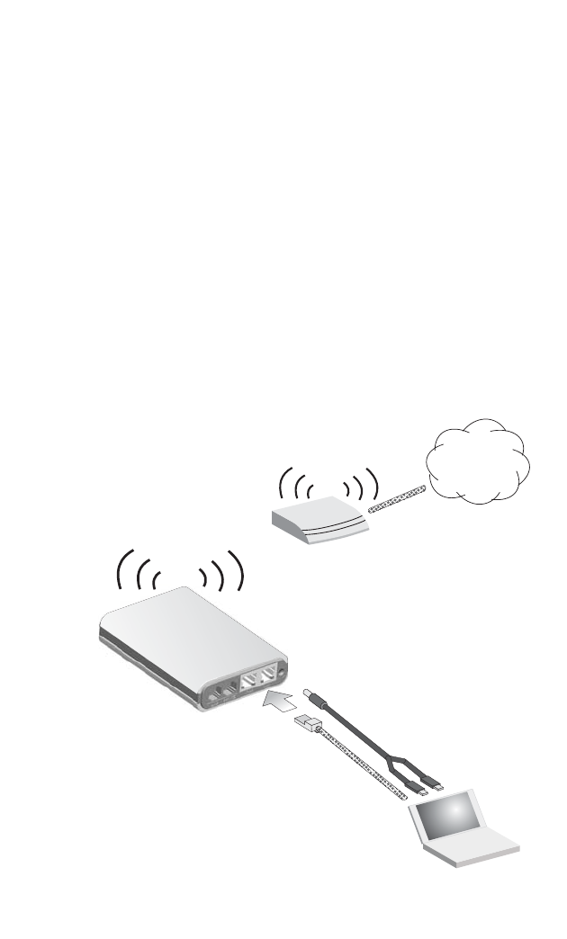
Internet Gateway
Used as a gateway, the unit routes traffic between an Internet connected cable or
ADSL modem, and wired or wireless PCs or notebooks.
To connect the Personal Mobile Gateway for use as an Internet gateway, follow
these steps:
1. Connect an Ethernet cable from the Personal Mobile Gateway’s WAN port to
your Internet connected cable or ADSL modem.
2. Connect an Ethernet cable from the Personal Mobile Gateway’s LAN port to
your PC. Alternatively, you can connect to a workgroup switch to support
multiple users. The Personal Mobile Gateway can support up to 32 wired or
wireless users.
Personal
Mobile Gateway
(Default IP 192.168.7.1)
Connect
LAN port
to PC
Connect
WAN port
to Cable/DSL
modem
Notebook PC
Cable/DSL Modem
Internet
12
Connect
AC power
adapter to
power source
3
Connecting the Personal Mobile Gateway
2-2
3. Power on the Personal Mobile Gateway by connecting the AC power adapter
and plugging it into a power source.
4. Use your PC’s web browser to access the Personal Mobile Gateway’s
management interface and run the Setup Wizard to make any configuration
changes (refer to the Management Guide for details). The Personal Mobile
Gateway has a default IP address of 192.168.7.1 and a subnet mask of
255.255.255.0.
Note: If your PC has an IP address assigned by DHCP (Dynamic Host Configuration
Protocol) or is set on the same subnet as the Personal Mobile Gateway (that is,
the PC’s IP address starts 192.168.7.x), you can connect immediately to the web
management interface. Otherwise, you must first change your PC’s IP address to
be on the same subnet as the Personal Mobile Gateway.
Wireless Client
Used as a wireless client, the Personal Mobile Gateway can connect your PC to any
nearby access point.
Personal
Mobile Gateway
(Default IP 192.168.7.1)
Connect
LAN port
to PC
Notebook PC
Access Point
Internet
1
Connect
Y-type USB
power cable
to PC
2

Wireless Access Point
2-3
To connect the Personal Mobile Gateway for use as a wireless client, follow these
steps:
1. Connect an Ethernet cable from the Personal Mobile Gateway’s LAN port to
your PC.
2. Power on the Personal Mobile Gateway by connecting the Y-type power cable
to the unit and plugging the USB connectors into two of your PC’s USB ports.
Alternatively, if you have access to a nearby power source, you can also power
on the Personal Mobile Gateway by using the AC power adapter.
3. Use your PC’s web browser to access the Personal Mobile Gateway’s
management interface and run the Setup Wizard to scan the area and select a
specific access point for connection (refer to the Management Guide for
details). The Personal Mobile Gateway has a default IP address of 192.168.7.1
and a subnet mask of 255.255.255.0.
Note: If your PC has an IP address assigned by DHCP (Dynamic Host Configuration
Protocol) or is set on the same subnet as the Personal Mobile Gateway (that is,
the PC’s IP address starts 192.168.7.x), you can connect immediately to the web
management interface. Otherwise, you must first change your PC’s IP address to
be on the same subnet as the Personal Mobile Gateway.
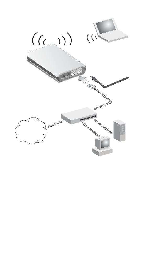
Wireless Access Point
Used as a wireless access point, the Personal Mobile Gateway connects to an
Ethernet LAN switch and extends the local network to associated wireless clients
(PCs or notebooks with 802.11b/g wireless capability). From any nearby location,
you can then make a wireless connection to the Personal Mobile Gateway and
access the Ethernet network resources, including local servers and the Internet.
Connecting the Personal Mobile Gateway
2-4
To connect the Personal Mobile Gateway for use as an access point, follow these
steps:
1. Connect an Ethernet cable from the Personal Mobile Gateway’s LAN port to
your local network switch.
2. Power on the Personal Mobile Gateway by connecting the AC power adapter
and plugging it into a power source.
3. From a PC on the local network, use a web browser to access the Personal
Mobile Gateway’s user interface and run the Setup Wizard to configure the
access point service (refer to the Management Guide for details). The Personal
Mobile Gateway has a default IP address of 192.168.7.1 and a subnet mask of
255.255.255.0. If the default IP address is not compatible with the local
network, you can first configure the Personal Mobile Gateway from a direct
connection to a PC before installing the unit in the network.
Personal
Mobile Gateway
(Default IP 192.168.7.1)
Connect to web
interface from LAN
PC and use Setup
Wizard to configure
access point service
Connect
LAN port
to Ethernet
LAN switch
Notebook PC
Internet
1
3
Connect
AC power
adapter to
power source
2
Desktop PC
Server
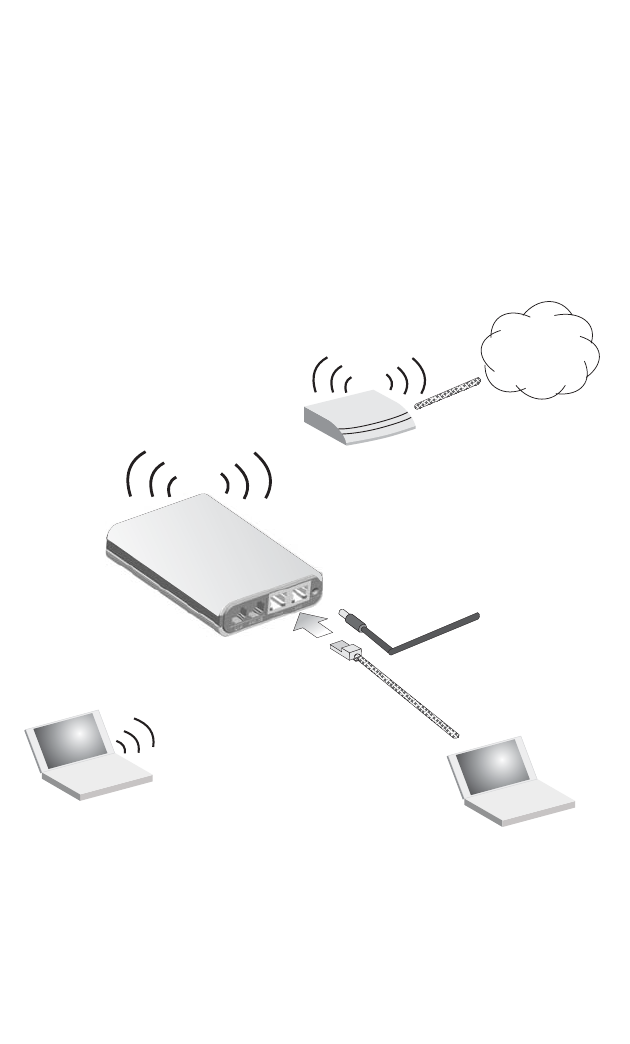
Wireless Repeater
2-5
Wireless Repeater
The Personal Mobile Gateway can also operate in a wireless “repeater” mode to
extend the range of other wireless access points. The unit forwards wireless traffic
between wireless-enabled PCs and an access point.
In repeater mode, the Personal Mobile Gateway does not forward wireless traffic to
its LAN port. The LAN port can only be used for management access to the web
interface. Note that when the unit operates in this mode, only half the normal
wireless traffic throughput is possible. This is because the unit has to receive and
then re-transmit all data on the same wireless channel.
To connect the Personal Mobile Gateway for use as a wireless repeater, follow these
steps:
1. Power on the Personal Mobile Gateway by connecting the AC power adapter
and plugging it into a power source.
2. Connect an Ethernet cable from the Personal Mobile Gateway’s LAN port to
your PC.
Personal
Mobile Gateway
(Default IP 192.168.7.1)
Connect
LAN port
to PC
Notebook PC
Access Point
Internet
2
Notebook PC
Connect
AC power
adapter to
power source
1
Connect to web
interface and
manually set
repeater mode
3

Connecting the Personal Mobile Gateway
2-6
3. Use your PC’s web browser to access the Personal Mobile Gateway’s
management interface and manually set the unit to repeater mode (refer to the
Management Guide for details). The Personal Mobile Gateway has a default IP
address of 192.168.7.1 and a subnet mask of 255.255.255.0.
Note: If your PC has an IP address assigned by DHCP (Dynamic Host Configuration
Protocol) or is set on the same subnet as the Personal Mobile Gateway (that is,
the PC’s IP address starts 192.168.7.x), you can connect immediately to the web
management interface. Otherwise, you must first change your PC’s IP address to
be on the same subnet as the Personal Mobile Gateway.
4. When you have completed setting the Personal Mobile Gateway to repeater
mode, you can remove the PC connection to the unit.
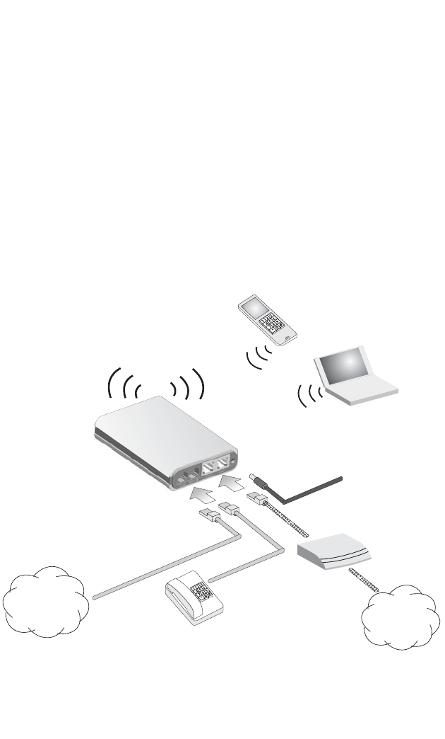
VoIP Telephony Functions
2-7
VoIP Telephony Functions
The Personal Mobile Gateway can function as a VoIP gateway for making telephone
calls over the Internet. Using the Internet to make VoIP calls to any other VoIP user
in the world is essentially free, and even calls to regular PSTN (Public Switched
Telephone Network) phones are much cheaper than making a traditional long
distance calls.
The Personal Mobile Gateway enables VoIP calls to be made using a regular
(analog) telephone set, as well as a PC or VoIP phone. The regular telephone can
also be used to make PSTN calls through the Personal Mobile Gateway.
The Personal Mobile Gateway uses standard Session Initiation Protocol (SIP)
technology to make VoIP calls. When you have connected the unit in either gateway,
access point, wireless client, or repeater mode, use the web management interface
to set up the SIP parameters. Refer to the Management Guide for more information
on VoIP and SIP.
Personal
Mobile Gateway
(Default IP 192.168.7.1)
Connect
LINE port
to PSTN jack
Cable/DSL
Modem
Internet
1
Notebook PC
Wireless
VoIP Phone
Standard
(Analog)
Telephone
Public Switched
Telephione
Network (PSTN)
Connect
PHONE port
to standard
telephone
2

Connecting the Personal Mobile Gateway
2-8
To connect the Personal Mobile Gateway to use its telephony functions, first connect
and configure the Personal Mobile Gateway in the operating mode you want to use
(see the appropriate section in this chapter.), then follow these steps:
1. Connect an RJ-11 telephone cable from the Personal Mobile Gateway’s
PHONE port to your standard (analog) telephone set.
2. Connect an RJ-11 telephone cable from the Personal Mobile Gateway’s LINE
port to an available PSTN telephone jack.
3. Use your PC’s web browser to access the Personal Mobile Gateway’s
management interface and configure your VoIP and SIP settings (refer to the
Management Guide for details).
Note: To make a PSTN call through the Personal Mobile Gateway, you must first dial
“0” on the standard telephone set. The default on the PHONE port is for VoIP
calls.

A-1
Appendix A: Troubleshooting
Diagnosing LED Indicators
Note: For information on troubleshooting wireless connectivity issues, refer to the
Management Guide.
Troubleshooting Chart
Symptom Action
Power LED is Off • AC power adapter may be disconnected. Check connections between
the Personal Mobile Gateway, the power adapter, and the wall outlet.
Power LED is Amber for more
than 20 seconds • The Personal Mobile Gateway has detected a system error. Reboot
the Personal Mobile Gateway to try and clear the condition.
• If the condition does not clear, contact your local dealer for assistance.
WAN or LAN link LED is Off • Verify that the Personal Mobile Gateway and attached device are
powered on.
• Be sure the cable is plugged into both the Personal Mobile Gateway
and corresponding device.
• Verify that the proper cable type is used and its length does not exceed
specified limits.
• Check the cable connections for possible defects. Replace the
defective cable if necessary.

Troubleshooting
A-2
B-1
Appendix B: Cables and Pinouts
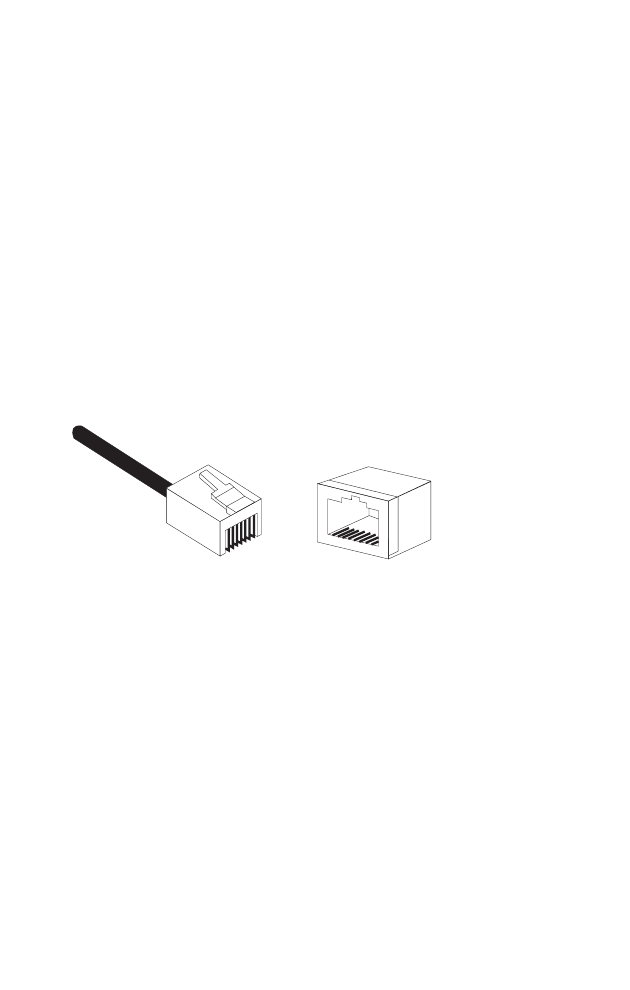
Twisted-Pair Cable Assignments
For 10/100BASE-TX connections, a twisted-pair cable must have two pairs of wires.
Each wire pair is identified by two different colors. For example, one wire might be
green and the other, green with white stripes. Also, an RJ-45 connector must be
attached to both ends of the cable.
Caution: Each wire pair must be attached to the RJ-45 connectors in a specific
orientation. (See “Straight-Through Wiring” on page B-2 and “Crossover
Wiring” on page B-2 for an expADSL connectionation.)
Caution: DO NOT plug a phone jack connector into the RJ-45 port. Use only twisted-pair
cables with RJ-45 connectors that conform with FCC standards.
The following figure illustrates how the pins on the RJ-45 connector are numbered.
Be sure to hold the connectors in the same orientation when attaching the wires to
the pins.
10/100BASE-TX Pin Assignments
Use unshielded twisted-pair (UTP) or shielded twisted-pair (STP) cable for RJ-45
connections: 100-ohm Category 3 or better cable for 10 Mbps connections, or
100-ohm Category 5 or better cable for 100 Mbps connections. Also be sure
that the
length of any twisted-pair connection does not exceed 100 meters (328 feet).
The RJ-45 port on the personal mobile gateway supports automatic MDI/MDI-X
operation, so you can use straight-through or crossover cables for all network
connections to PCs, switches, or hubs. In straight-through cable, pins 1, 2, 3, and 6,
at one end of the cable, are connected straight through to pins 1, 2, 3, and 6 at the
other end of the cable.
1
881
Cables and Pinouts
B-2
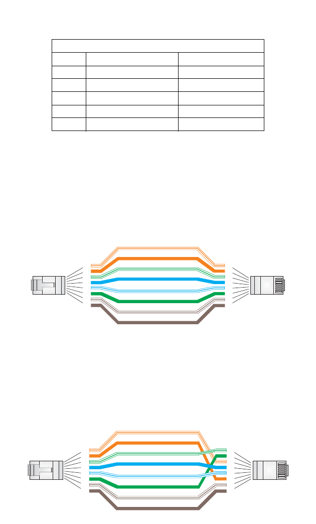
Straight-Through Wiring
If the twisted-pair cable is to join two ports and only one of the ports has an internal
crossover (MDI-X), the two pairs of wires must be straight-through.
Crossover Wiring
If the twisted-pair cable is to join two ports and either both ports are labeled with an
“X” (MDI-X) or neither port is labeled with an “X” (MDI), a crossover must be
implemented in the wiring.
Table B-1. 10/100BASE-TX MDI and MDI-X Port Pinouts
Pin MDI-X Signal Name MDI Signal Name
1 Receive Data plus (RD+) Transmit Data plus (TD+)
2 Receive Data minus (RD-) Transmit Data minus (TD-)
3Transmit Data plus (TD+) Receive Data plus (RD+)
6Transmit Data minus (TD-) Receive Data minus (RD-)
4,5,7,8 Not used Not used
Note: The “+” and “-” signs represent the polarity of the wires that make
up each wire pair.
White/Orange Stripe
Orange
White/Green Stripe
Green
1
2
3
4
5
6
7
8
1
2
3
4
5
6
7
8
EIA
/
TIA 568B RJ-45 Wiring
S
tandard
10/100BASE-TX Straight-through Cable
End A End B
Blue
White/Blue Stripe
Brown
White/Brown Stripe
White/Orange Stripe
Orange
White/Green Stripe
1
2
3
4
5
6
7
8
1
2
3
4
5
6
7
8
EIA
/
TIA 568B RJ-45 Wiring
S
tandard
10/100BASE-TX Crossover Cable
End A End B
Green
Blue
White/Blue Stripe
Brown
White/Brown Stripe
RJ-11 Ports
B-3
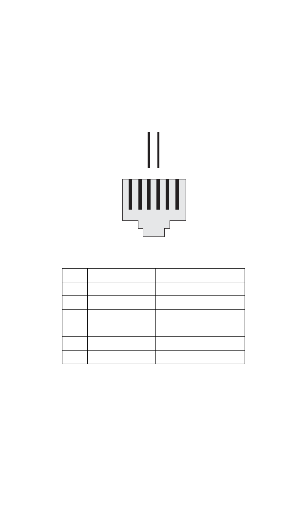
RJ-11 Ports
Standard telephone RJ-11 connectors and cabling can be found in several common
wiring patterns. These six-pin connectors can accommodate up to three wire pairs
(three telephone lines), but usually only one or two pairs of conductor pins and wires
are implemented.
The RJ-11 ports on the side of the Personal Mobile Gateway contain only one wire
pair on the inner pins (3 and 4).
Pin Signal Name Wire Color
1Not used
2Not used
3Line 1 Ring Red or Blue/White
4Line 1 Tip Green or White/Blue
5Not used
6Not used
123456
Red or
Blue/White
Green or
White/Blue
RT
R = Ring T = Tip

Cables and Pinouts
B-4

C-1
Appendix C: Specifications
Physical Specifications
Ports
2 10/100BASE-TX ports, RJ-45 connector, auto MDI/X
10BASE-T: RJ-45 (100-ohm, UTP cable; Category 3 or better)
100BASE-TX: RJ-45 (100-ohm, UTP cable; Category 5 or better)
1 FXS port (PHONE), RJ-11 connector
1 FXO port (LINE), RJ-11 connector
LED Indicators
Power, Internet, Wireless (802.11b/g Wireless Link/signal strength),
WAN (Ethernet Link/Activity, Speed), LAN (Ethernet Link/Activity, Speed)
AC Power Adapter
Vendor: PHIH
Model Number: PSC11R-050
Input: 100-240 VAC, 50-60 Hz
Output: 5 VDC, 2A
Unit Power Supply
DC Input: 5 VDC, 1 A maximum
Power Consumption: < 5 W
Physical Size
105 x 78.67 x 24.7 mm (4.13 x 3.1 x 0.97 in)
Weight
0.1 kg (0.22 lbs)
Temperature
Operating: -10 to 50 °C (14 to 122 °F)
Storage: -40 to 70 °C (-40 to 158 °F)
Humidity
5% to 95% (non-condensing)

Specifications
C-2
Wireless Specifications
Maximum 802.11b/g Channels
FCC/IC: 1-11
ETSI: 1-13
France: 10-13
Operating Frequency
2.4 ~ 2.4835 GHz (US, Canada, ETSI)
Maximum Wireless Clients
32
Data Rate
802.11g: 6, 9, 11, 12, 18, 24, 36, 48, 54 Mbps (automatic fall back)
802.11b: 1, 2, 5.5, 11 Mbps (automatic fall back)
Modulation Type
802.11g: CCK, BPSK, QPSK, OFDM
802.11b: CCK, BPSK, QPSK
RF Output Power
802.11b: 18 dBm
802.11g: 14 dBm
VoIP Specifications
Voice Signaling Protocol
SIP v2
Voice Codec
G.711
G. 7 2 6
G.729 a, b
Voice Quality
VAD (Voice Activity Detection)
CNG (Comfortable Noise Generation)
Echo cancellation (G.165/G.168 echo canceller) up to 16 milliseconds
Adaptive jitter buffer, 70 to 200 milliseconds
DTMF tone detection and generation
Call progress generation
Custom tone generation

Compliances
C-3
Call Features
Call transfer
Call waiting/hold/retrieve
3-way conference call
Call-ID number and name
Call-ID block
Anonymous call blocking
T. 38 f a x r ela y
Dial plan (E.164 dialing plan)
Do not disturb setting
Speed dial
Repeat dialing on busy
Call return
Call forwarding: No Answer/Busy/All
Distinctive ringing
Compliances
Emissions
FCC Part 15B Class B
FCC ID grant
IC RSS-210
IC ID grant
EN 55022 Class B
EN 55024
Radio Signal Certification
FCC Part 15C 15.247, 15.207
EN 300-328
EN 301-489
Temperature
IEC 68-2-14
Vibration
IEC 68-2-36, IEC 68-2-6
Shock
IEC 68-2-29
Drop
IEC 68-2-32

Specifications
C-4
Safety
UL/cUL (UL 60950)
EN 60950 (CB)
TUV/GS
Standards
IEEE Std. 802.3-2002 10BASE-T and 100BASE-TX
IEEE 802.11b, g
Wi-Fi 11b/g, WPA
UPnP
Model Number: VG007
Pub. Number: 149100032900E, E122005-R01