Accton Technology WA4101ACCAA hp procurve wireless AP 420 na User Manual ig
Accton Technology Corp hp procurve wireless AP 420 na ig
UserManual.wiki
>
Accton Technology
>
WA4101ACCAA User Manual
User Manual
Navigation menu
Upload a User Manual
Namespaces
Wiki Guide
HTML
PDF
Info
Views
User Manual
Discussion / Help
Navigation
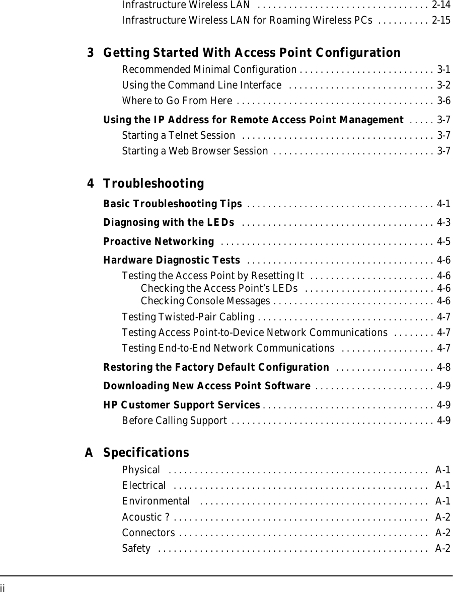
![2-12Installing the wireless AP 420 ww/naInstallation ProceduresInstalling the wireless AP 420 ww/naDirect Console AccessTo connect a console to the access point, follow these steps:1. Connect the PC or terminal to the access point’s Console port using the console cable included with the AP 420 ww/na. (If your PC or terminal has a 25-pin serial connector, first attach a 9-pin to 25-pin straight-through adapter at one end of the console cable.)2. Turn on the terminal or PC’s power and, if using a PC, start the PC terminal program. 3. Enter “admin” at the “Username:” prompt, and press the [Enter] key at the “Password” prompt. You will then see the access point console command (CLI) prompt, for example:hp procurve wireless AP 420 ww/naIf you want to continue with console management of the access point at this time, see chapter 3, “Getting Started With Access Point Configuration” for some basic configuration steps. For more detailed information, refer to the Management and Configuration Guide, which is on the Documentation CD-ROM that came with your access point.Console portConsole cable supplied with the access pointPC running a terminal emulator program, or a VT-100 terminal](https://usermanual.wiki/Accton-Technology/WA4101ACCAA/User-Guide-363689-Page-26.png)

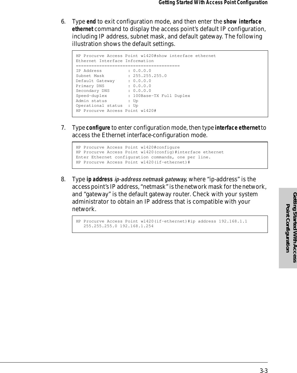
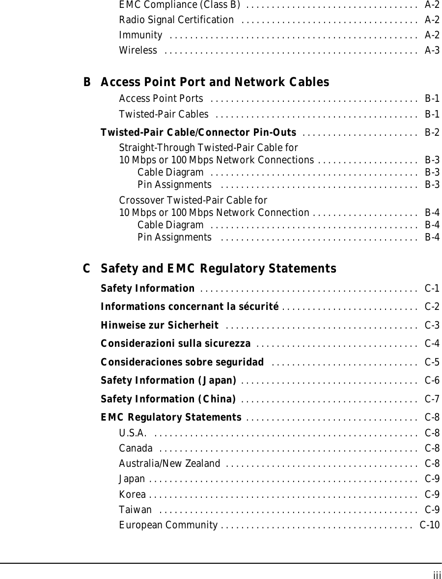
![3-2Getting Started With Access Point ConfigurationGetting Started With Access Point ConfigurationNote By default, the access point is configured to acquire an IP address configura-tion from a DHCP server. To use DHCP instead of the manual method described in this chapter, see “DHCP Operation” in the Management and Configuration Guide, which is on the Documentation CD-ROM that came with your access point.Using the Command Line InterfaceThe quickest and easiest way to minimally configure the access point for management and password protection in your network is to use a direct console connection to the access point, start a console session, and access the command line interface (CLI).1. Using the method described in the preceding chapter, connect a terminal device to the access point, and press [Enter] to initiate the console connection.2. Enter “admin” for the user name. The default password is null, so just press [Enter] at the password prompt. The CLI prompt appears displaying the access point’s model number.3. Type configure to enter global configuration mode.4. Type username username to create a user name for the Manager, where “username” can consist of 3 to 16 alphanumeric characters and is case sensitive.5. Type password password to create a password for the Manager, where “password” can consist of up to 8 alphanumeric characters and is case sensitive.Username: adminPassword:HP Procurve Access Point wl420#HP Procurve Access Point wl420#configureEnter configuration commands, one per line. End with CTRL/ZHP Procurve Access Point wl420(config)#HP Procurve Access Point wl420#configureEnter configuration commands, one per line. End with CTRL/ZHP Procurve Access Point wl420(config)#username adminHP Procurve Access Point wl420(config)#HP Procurve Access Point wl420#configureEnter configuration commands, one per line. End with CTRL/ZHP Procurve Access Point wl420(config)#password [password]HP Procurve Access Point wl420(config)#](https://usermanual.wiki/Accton-Technology/WA4101ACCAA/User-Guide-363689-Page-32.png)