Accton Technology WA6101BCC WLAN Access Point 2221 User Manual AccessPointUG
Accton Technology Corp WLAN Access Point 2221 AccessPointUG
Manual

Part No. 214853-B
June 2003
4655 Great America Parkway
Santa Clara, CA 95054
Using the Nortel Networks
Wireless LAN Access Point
2220/2221-802.11b-only
This multi-product manual describes some features not
available on the 2221-802.11b-only Access Point. The
802.11a radio described in this manual is unavailable on
the 2221-802.11b-only Access Point.

2
214853-B
Copyright © 2003 Nortel Networks
All rights reserved. June 2003.
No part of this publication may be reproduced, stored in a retrieval system, or transmitted in any form or by any means,
whether electronic, mechanical, photocopying, recording or otherwise without the prior writing of the publisher.
Windows 98SE/2000/ME/XP are trademarks of Microsoft Corp.
Pentium is a trademark of Intel.
Nortel Networks and the Nortel Networks logo are trademarks of Nortel Networks, Inc.
Multi-Region Product Documentation
This document may describe features that are not available in your region due to local regulations.
This document describes the use of the 802.11a radio. This feature is unavailable in Israel, Greece and Spain due to local
regulations.
Compliances
Federal Communication Commission Interference Statement
This equipment has been tested and found to comply with the limits for a Class B digital device, pursuant to Part 15 of
the FCC Rules. These limits are designed to provide reasonable protection against harmful interference in a residential
installation. This equipment generates, uses and can radiate radio frequency energy and, if not installed and used in
accordance with instructions, may cause harmful and, if not installed and used in accordance with instructions, may
cause harmful interference to radio communications. However, there is no guarantee that the interference will not occur
in a particular installation. If this equipment does cause harmful interference to radio or television reception, which can
be determined by turning the equipment off and on, the user is encouraged to try to correct the interference by one or
more of the following measures:
• Reorient the receiving antenna
• Increase the separation between the equipment and receiver
• Connect the equipment into an outlet on a circuit different from that to which the receiver is connected
• Consult the dealer or an experienced radio/TV technician for help
FCC Caution: To assure continued compliance, (example - use only shielded interface cables when connecting to
computer or peripheral devices). Any changes or modifications not expressly approved by the party responsible for
compliance could void the user’s authority to operate this equipment.
This device complies with Part 15 of the FCC Rules. Operation is subject to the following two conditions: (1) This
device may not cause harmful interference, and (2) this device must accept any interference received, including
interference that may cause undesired operation.
European Community Notice
Marking by the symbol indicates compliance with the Essential Requirements of the R&TTE
Directive of the European Union (1999/5/EC). This equipment meets the following conformance standards:
EN 301 893, EN 301 489-17, EN 60950, ETS 300 328-2
This device should not be operated in 802.11a mode in the following European Community countries: Greece and
Spain. The radio spectrum authorities in these countries do not currently allow operation of this radio device in the
5GHz bands.

3
Using the Nortel Networks Wireless LAN Access Point 2220/2221
This device is restricted to indoor use when operated in the European Community using channels in the 5150-5350
MHz band to reduce the potential for harmful interference to other users of the band.
To remain in conformance with European National spectrum usage laws, the channel and power settings must be
configured during installation to match the country in which the device is operating. This will ensure the Access Point
operates using the channels and transmit power specified by the applicable radio regulatory authority (refer to table
below).
Please refer to the Radio Interface sections of the using guide to configure the channel and power settings.
European Community Declaration of Conformity:
Allowable Frequencies of Operation Countries
5150-5250 MHz
(Channels 36, 40, 44, 48)
Austria, Germany, Liechtenstein, Switzerland
5150-5350 MHz
(Channels 36, 40, 44, 48, 52, 56, 60, 64)
Belgium, France, Ireland, U.K.
5150-5350 & 5470-5725 MHz
(Channels 36, 40, 44, 48, 52, 56, 60, 64, 100, 104, 108,
112, 116, 120, 124, 128, 132, 136, 140)
Denmark, Finland, Iceland, Italy, Luxembourg, Netherlands, Norway, Portugal,
Sweden
2446.5Mhz - 2483.5Mhz
(Channels 10,11,12,13)
France
English Hereby, Nortel Networks, declares that this Radio LAN device is in compliance with the essential
requirements and other relevant provisions of Directive 1999/5/EC.
Finnish Valmistaja Nortel Networks vakuuttaa täten että Radio LAN device tyyppinen laite on direktiivin
1999/5/EY oleellisten vaatimusten ja sitä koskevien direktiivin muiden ehtojen mukainen.
Dutch Hierbij verklaart Nortel Networks dat het toestel Radio LAN device in overeenstemming is met de
essentiële eisen en de andere relevante bepalingen van richtlijn 1999/5/EG
Bij deze verklaart Nortel Networks dat deze Radio LAN device voldoet aan de essentiële eisen en
aan de overige relevante bepalingen van Richtlijn 1999/5/EC.
French Par la présente Nortel Networks déclare que l'appareil Radio LAN device est conforme aux
exigences essentielles et aux autres dispositions pertinentes de la directive 1999/5/CE
Par la présente, Nortel Networks déclare que ce Radio LAN device est conforme aux exigences
essentielles et aux autres dispositions de la directive 1999/5/CE qui lui sont applicables
Swedish Härmed intygar Nortel Networks att denna Radio LAN device står I överensstämmelse med de
väsentliga egenskapskrav och övriga relevanta bestämmelser som framgår av direktiv 1999/5/EG.
Danish Undertegnede Nortel Networks erklærer herved, at følgende udstyr Radio LAN device overholder
de væsentlige krav og øvrige relevante krav i direktiv 1999/5/EF
German Hiermit erklärt Nortel Networks, dass sich dieser/diese/dieses Radio LAN device in
Übereinstimmung mit den grundlegenden Anforderungen und den anderen relevanten Vorschriften
der Richtlinie 1999/5/EG befindet". (BMWi)
4
214853-B
CAUTION STATEMENT:
FCC Radiation Exposure Statement
FCC RF Radiation Exposure Statement
This equipment complies with FCC RF radiation exposure limits set forth for an uncontrolled environment. This
equipment should be installed and operated with a minimum distance of 20 centimeters (8 inches) between the radiator
and your body. This transmitter must not be co-located or operated in conjunction with any other antenna or transmitter.
This device is restricted to indoor use only.
Industry Canada - Class B
This digital apparatus does not exceed the Class B limits for radio noise emissions from digital apparatus as set out in the
interference-causing equipment standard entitled “Digital Apparatus,” ICES-003 of the Department of Communications.
Cet appareil numérique respecte les limites de bruits radioélectriques applicables aux appareils numériques de Classe B
prescrites dans la norme sur le matériel brouilleur: “Appareils Numériques,” NMB-003 édictée par le ministère des
Communications.
Hiermit erklärt Nortel Networks die Übereinstimmung des Gerätes Radio LAN device mit den
grundlegenden Anforderungen und den anderen relevanten Festlegungen der Richtlinie 1999/5/EG.
(Wien)
Greek Ã≈ ‘«Õ —¡–œ’”¡ Nortel Networks ƒ«ÀŸÕ≈… œ‘… Radio LAN device ”’ÃÃœ–÷ŸÕ≈‘¡…
—–œ” ‘…” œ’”…Ÿƒ≈…” ¡—¡…‘«”≈…” ¡… ‘…” Àœ…—≈” ”◊≈‘…≈” ƒ…¡‘¡Œ≈…” ‘«”
œƒ«√…¡” 1999/5/≈
Italian Con la presente Nortel Networks dichiara che questo Radio LAN device è conforme ai requisiti
essenziali ed alle altre disposizioni pertinenti stabilite dalla direttiva 1999/5/CE.
Spanish Por medio de la presente Nortel Networks declara que el Radio LAN device cumple con los
requisitos esenciales y cualesquiera otras disposiciones aplicables o exigibles de la Directiva 1999/
5/CE
Portuguese Nortel Networks declara que este Radio LAN device está conforme com os requisitos essenciais e
outras disposições da Directiva 1999/5/CE.
Warning: Use ONLY the power adapter supplied by Nortel Networks for this product. Otherwise, the
product may be damaged. Contact your Nortel Networks representative to order the power adapter.
Warning: To avoid bodily injury from hazardous electrical shock and current, never remove the top cover
of the device. There are no user-serviceable components inside.
5
Using the Nortel Networks Wireless LAN Access Point 2220/2221
Warning: Um gesundheitliche Schäden zu vermeiden, öffnen Sie nie den oberen Gehäusedeckel. Es
befinden sich keine durch den Benutzer zu wartenden Teile im Inneren.
Warning: pour éviter tout risque d’électrocution, ne retirez jamais le couvercle du module. Celui-ci ne
comprend aucun composant pouvant être dépanné par l’utilisateur.
Advertencia: No retire nunca la cubierta superior del dispositivo, ya que podría resultar herido como
consecuencia de una descarga eléctrica y de corriente. Dentro del dispositivo no hay ningún componente que
pueda reparar el usuario.
Avviso: per evitare lesioni personali da scosse elettriche e tensioni pericolose, non rimuovere mai il
coperchio superiore del dispositivo. Questo prodotto non contiene parti riparabili dall’utente.

6
214853-B

7
Using the Nortel Networks Wireless LAN Access Point 2220/2221
Contents
Preface . . . . . . . . . . . . . . . . . . . . . . . . . . . . . . . . . . . . . . . . . . . . . . . . . . . . . . 15
Introduction . . . . . . . . . . . . . . . . . . . . . . . . . . . . . . . . . . . . . . . . . . . . . . . . . . . . . . . . . 15
Package Checklist . . . . . . . . . . . . . . . . . . . . . . . . . . . . . . . . . . . . . . . . . . . . . . . . . 16
Hardware Description . . . . . . . . . . . . . . . . . . . . . . . . . . . . . . . . . . . . . . . . . . . . . . 16
Ethernet Compatibility . . . . . . . . . . . . . . . . . . . . . . . . . . . . . . . . . . . . . . . . . . . 16
Power over Ethernet . . . . . . . . . . . . . . . . . . . . . . . . . . . . . . . . . . . . . . . . . . . . 16
LED Indicators . . . . . . . . . . . . . . . . . . . . . . . . . . . . . . . . . . . . . . . . . . . . . . . . . 16
System Requirements . . . . . . . . . . . . . . . . . . . . . . . . . . . . . . . . . . . . . . . . . . . . . . 18
Chapter 1
Hardware Installation. . . . . . . . . . . . . . . . . . . . . . . . . . . . . . . . . . . . . . . . . . . 19
Chapter 2
Network Configuration and Planning. . . . . . . . . . . . . . . . . . . . . . . . . . . . . . 21
Network Topologies . . . . . . . . . . . . . . . . . . . . . . . . . . . . . . . . . . . . . . . . . . . . . . . . . . . 21
Ad Hoc Wireless LAN
(no AP or Bridge) . . . . . . . . . . . . . . . . . . . . . . . . . . . . . . . . . . . . . . . . . . . . . . . . 21
Infrastructure Wireless LAN . . . . . . . . . . . . . . . . . . . . . . . . . . . . . . . . . . . . . . . . . . 22
Infrastructure Wireless LAN for Roaming Wireless PCs . . . . . . . . . . . . . . . . . . . . 22
Chapter 3
System Configuration . . . . . . . . . . . . . . . . . . . . . . . . . . . . . . . . . . . . . . . . . . 24
Accessing the CLI . . . . . . . . . . . . . . . . . . . . . . . . . . . . . . . . . . . . . . . . . . . . . . . . . . . . 24
Using the Web Management Interface . . . . . . . . . . . . . . . . . . . . . . . . . . . . . . . . . . . . . 25
Setup Wizard . . . . . . . . . . . . . . . . . . . . . . . . . . . . . . . . . . . . . . . . . . . . . . . . . . . . . . . . 26
Channel . . . . . . . . . . . . . . . . . . . . . . . . . . . . . . . . . . . . . . . . . . . . . . . . . . . . . . . . 29
802.11a . . . . . . . . . . . . . . . . . . . . . . . . . . . . . . . . . . . . . . . . . . . . . . . . . . . . . . 29
802.11b . . . . . . . . . . . . . . . . . . . . . . . . . . . . . . . . . . . . . . . . . . . . . . . . . . . . . . 29
IP Configuration . . . . . . . . . . . . . . . . . . . . . . . . . . . . . . . . . . . . . . . . . . . . . . . . . . . 30

8Contents
214853-B
Security . . . . . . . . . . . . . . . . . . . . . . . . . . . . . . . . . . . . . . . . . . . . . . . . . . . . . . . . . 31
64-Bit Manual Entry . . . . . . . . . . . . . . . . . . . . . . . . . . . . . . . . . . . . . . . . . . . . 32
128-Bit Manual Entry . . . . . . . . . . . . . . . . . . . . . . . . . . . . . . . . . . . . . . . . . . . 32
Advanced Setup . . . . . . . . . . . . . . . . . . . . . . . . . . . . . . . . . . . . . . . . . . . . . . . . . . 33
System . . . . . . . . . . . . . . . . . . . . . . . . . . . . . . . . . . . . . . . . . . . . . . . . . . . . . . . . . . . . .34
Identification . . . . . . . . . . . . . . . . . . . . . . . . . . . . . . . . . . . . . . . . . . . . . . . . . . . . . 34
TCP / IP Settings . . . . . . . . . . . . . . . . . . . . . . . . . . . . . . . . . . . . . . . . . . . . . . . . . . 35
RADIUS . . . . . . . . . . . . . . . . . . . . . . . . . . . . . . . . . . . . . . . . . . . . . . . . . . . . . . . . . 36
PPPoE Settings . . . . . . . . . . . . . . . . . . . . . . . . . . . . . . . . . . . . . . . . . . . . . . . . . . . 37
Authentication . . . . . . . . . . . . . . . . . . . . . . . . . . . . . . . . . . . . . . . . . . . . . . . . . . . . 38
802.1x Setup . . . . . . . . . . . . . . . . . . . . . . . . . . . . . . . . . . . . . . . . . . . . . . . . . . . . . 39
Local MAC Authentication . . . . . . . . . . . . . . . . . . . . . . . . . . . . . . . . . . . . . . . . . . . 39
Filter Control . . . . . . . . . . . . . . . . . . . . . . . . . . . . . . . . . . . . . . . . . . . . . . . . . . . . . 40
SNMP . . . . . . . . . . . . . . . . . . . . . . . . . . . . . . . . . . . . . . . . . . . . . . . . . . . . . . . . . . 41
Administration . . . . . . . . . . . . . . . . . . . . . . . . . . . . . . . . . . . . . . . . . . . . . . . . . . . . 42
Change Password . . . . . . . . . . . . . . . . . . . . . . . . . . . . . . . . . . . . . . . . . . . . . 43
Firmware Upgrade . . . . . . . . . . . . . . . . . . . . . . . . . . . . . . . . . . . . . . . . . . . . 43
Restore Factory Settings . . . . . . . . . . . . . . . . . . . . . . . . . . . . . . . . . . . . . . . 43
Reset Access Point . . . . . . . . . . . . . . . . . . . . . . . . . . . . . . . . . . . . . . . . . . . . 43
System Log . . . . . . . . . . . . . . . . . . . . . . . . . . . . . . . . . . . . . . . . . . . . . . . . . . . . . . 44
SNTP Server . . . . . . . . . . . . . . . . . . . . . . . . . . . . . . . . . . . . . . . . . . . . . . . . . . 44
Radio Interface B . . . . . . . . . . . . . . . . . . . . . . . . . . . . . . . . . . . . . . . . . . . . . . . . . . . . . 45
Radio Settings . . . . . . . . . . . . . . . . . . . . . . . . . . . . . . . . . . . . . . . . . . . . . . . . . . . . 45
Enable . . . . . . . . . . . . . . . . . . . . . . . . . . . . . . . . . . . . . . . . . . . . . . . . . . . . . . . 45
Radio Channel . . . . . . . . . . . . . . . . . . . . . . . . . . . . . . . . . . . . . . . . . . . . . . . . 46
Maximum Station Data Rate . . . . . . . . . . . . . . . . . . . . . . . . . . . . . . . . . . . . . . 46
Beacon Interval (20-1000) . . . . . . . . . . . . . . . . . . . . . . . . . . . . . . . . . . . . . . . . 46
DTIM Period (1-16384) . . . . . . . . . . . . . . . . . . . . . . . . . . . . . . . . . . . . . . . . . . 46
RTS Threshold (0-2347) . . . . . . . . . . . . . . . . . . . . . . . . . . . . . . . . . . . . . . . . . 47
Preamble Setting . . . . . . . . . . . . . . . . . . . . . . . . . . . . . . . . . . . . . . . . . . . . . . . 47
Security . . . . . . . . . . . . . . . . . . . . . . . . . . . . . . . . . . . . . . . . . . . . . . . . . . . . . . . . . 48
WEP (Wired Equivalent Privacy) . . . . . . . . . . . . . . . . . . . . . . . . . . . . . . . . . . . 48
Authentication Type Setup . . . . . . . . . . . . . . . . . . . . . . . . . . . . . . . . . . . . . . . . 48
Data Encryption . . . . . . . . . . . . . . . . . . . . . . . . . . . . . . . . . . . . . . . . . . . . . . . 49
Standard Key Setup (WEP Default: 128) . . . . . . . . . . . . . . . . . . . . . . . . . . . . 49

Contents 9
Using the Nortel Networks Wireless LAN Access Point 2220/2221
Radio Interface A . . . . . . . . . . . . . . . . . . . . . . . . . . . . . . . . . . . . . . . . . . . . . . . . . . . . . 50
Radio Settings . . . . . . . . . . . . . . . . . . . . . . . . . . . . . . . . . . . . . . . . . . . . . . . . . . . . 50
Enable . . . . . . . . . . . . . . . . . . . . . . . . . . . . . . . . . . . . . . . . . . . . . . . . . . . . . . . 50
Turbo Mode . . . . . . . . . . . . . . . . . . . . . . . . . . . . . . . . . . . . . . . . . . . . . . . . . . . 51
Radio Channel . . . . . . . . . . . . . . . . . . . . . . . . . . . . . . . . . . . . . . . . . . . . . . . . 51
Auto Channel Select . . . . . . . . . . . . . . . . . . . . . . . . . . . . . . . . . . . . . . . . . . . . 51
Transmit Power . . . . . . . . . . . . . . . . . . . . . . . . . . . . . . . . . . . . . . . . . . . . . . . . 52
Maximum Station Data Rate . . . . . . . . . . . . . . . . . . . . . . . . . . . . . . . . . . . . . . 52
Beacon Interval (20-1000) . . . . . . . . . . . . . . . . . . . . . . . . . . . . . . . . . . . . . . . . 52
DTIM Period (1-16384) . . . . . . . . . . . . . . . . . . . . . . . . . . . . . . . . . . . . . . . . . . 52
RTS Threshold (0-2347) . . . . . . . . . . . . . . . . . . . . . . . . . . . . . . . . . . . . . . . . . 53
Security . . . . . . . . . . . . . . . . . . . . . . . . . . . . . . . . . . . . . . . . . . . . . . . . . . . . . . . . . 54
WEP (Wired Equivalent Privacy) . . . . . . . . . . . . . . . . . . . . . . . . . . . . . . . . . . . 54
Authentication Type Setup . . . . . . . . . . . . . . . . . . . . . . . . . . . . . . . . . . . . . . . . 54
Data Encryption . . . . . . . . . . . . . . . . . . . . . . . . . . . . . . . . . . . . . . . . . . . . . . . 55
Standard Key Setup (WEP Default: 128) . . . . . . . . . . . . . . . . . . . . . . . . . . . . 55
Status . . . . . . . . . . . . . . . . . . . . . . . . . . . . . . . . . . . . . . . . . . . . . . . . . . . . . . . . . . . . . . 56
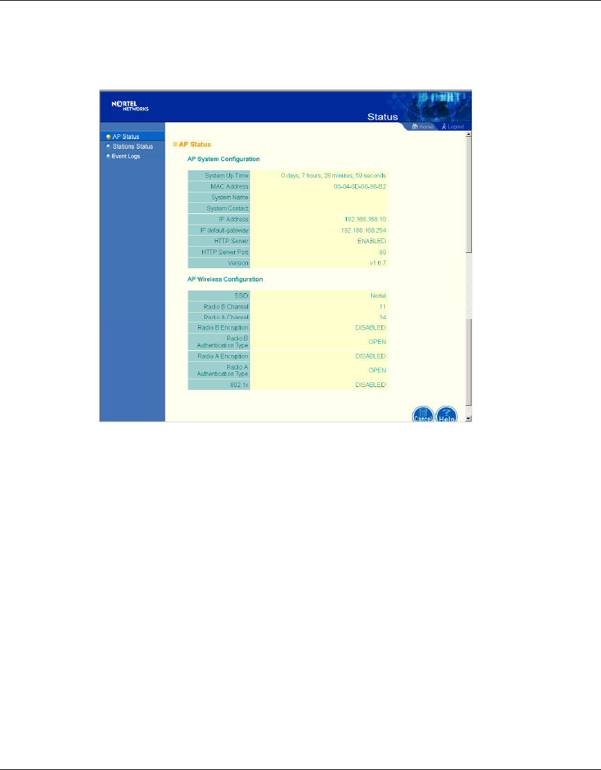
Access Point Status . . . . . . . . . . . . . . . . . . . . . . . . . . . . . . . . . . . . . . . . . . . . . . . . 57
Station Status . . . . . . . . . . . . . . . . . . . . . . . . . . . . . . . . . . . . . . . . . . . . . . . . . . . . 58
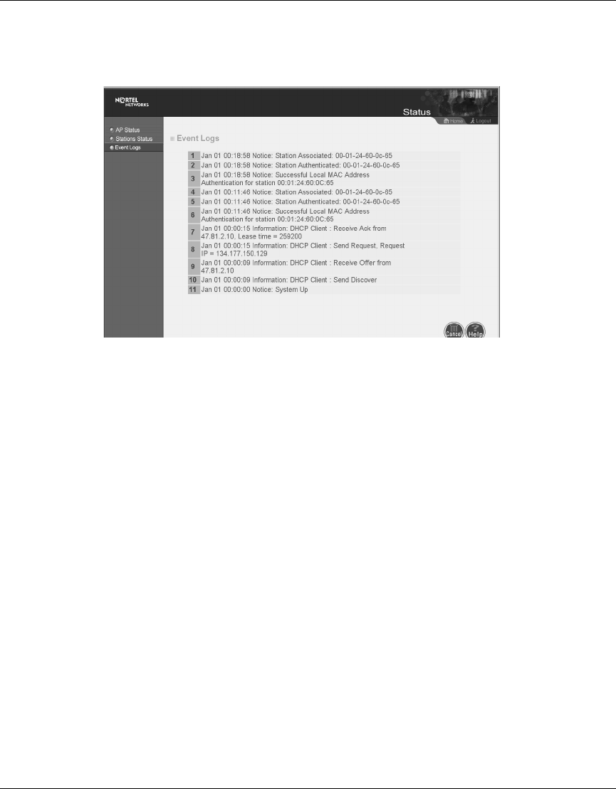
Event Logs . . . . . . . . . . . . . . . . . . . . . . . . . . . . . . . . . . . . . . . . . . . . . . . . . . . . . . . 59
Appendix A
Specifications. . . . . . . . . . . . . . . . . . . . . . . . . . . . . . . . . . . . . . . . . . . . . . . . . 61
Available Channels . . . . . . . . . . . . . . . . . . . . . . . . . . . . . . . . . . . . . . . . . . . . . . . . . . . 61
Maximum Clients . . . . . . . . . . . . . . . . . . . . . . . . . . . . . . . . . . . . . . . . . . . . . . . . . . . . 61
Data Rate . . . . . . . . . . . . . . . . . . . . . . . . . . . . . . . . . . . . . . . . . . . . . . . . . . . . . . . . . . . 61
Operating Frequency . . . . . . . . . . . . . . . . . . . . . . . . . . . . . . . . . . . . . . . . . . . . . . . . . 61
Power supply . . . . . . . . . . . . . . . . . . . . . . . . . . . . . . . . . . . . . . . . . . . . . . . . . . . . . . . 62
Output Power . . . . . . . . . . . . . . . . . . . . . . . . . . . . . . . . . . . . . . . . . . . . . . . . . . . . . . . 62
Physical Size . . . . . . . . . . . . . . . . . . . . . . . . . . . . . . . . . . . . . . . . . . . . . . . . . . . . . . . 62
Weight . . . . . . . . . . . . . . . . . . . . . . . . . . . . . . . . . . . . . . . . . . . . . . . . . . . . . . . . . . . . .62
LED Indicators . . . . . . . . . . . . . . . . . . . . . . . . . . . . . . . . . . . . . . . . . . . . . . . . . . . . . . 62
Management . . . . . . . . . . . . . . . . . . . . . . . . . . . . . . . . . . . . . . . . . . . . . . . . . . . . . . . . 62
Temperature . . . . . . . . . . . . . . . . . . . . . . . . . . . . . . . . . . . . . . . . . . . . . . . . . . . . . . . . 62
Humidity . . . . . . . . . . . . . . . . . . . . . . . . . . . . . . . . . . . . . . . . . . . . . . . . . . . . . . . . . . . 63

10 Contents
214853-B
Compliance Standards . . . . . . . . . . . . . . . . . . . . . . . . . . . . . . . . . . . . . . . . . . . . . . . . . 63
Standards . . . . . . . . . . . . . . . . . . . . . . . . . . . . . . . . . . . . . . . . . . . . . . . . . . . . . . . . . . 63
Warranty . . . . . . . . . . . . . . . . . . . . . . . . . . . . . . . . . . . . . . . . . . . . . . . . . . . . . . . . . . . 63
Appendix B
Template for placing the Access Point 2220/2221 . . . . . . . . . . . . . . . . . . . . 65
Appendix C
Mounting the Access Point 2220/2221 on a Drop Ceiling . . . . . . . . . . . . . . 67
Attaching the mounting bracket to a drop ceiling . . . . . . . . . . . . . . . . . . . . . . . . . . . . . 68
Attaching the Access Point 2220/2221 to the mounting bracket . . .. . . . . . . . . . . . . . . 68

11
Using the Nortel Networks Wireless LAN Access Point 2220/2221
Figures
Figure 1 LED indicators . . . . . . . . . . . . . . . . . . . . . . . . . . . . . . . . . . . . . . . . . . . . . 17
Figure 2 Rear Panel . . . . . . . . . . . . . . . . . . . . . . . . . . . . . . . . . . . . . . . . . . . . . . . . 20
Figure 3 Login screen . . . . . . . . . . . . . . . . . . . . . . . . . . . . . . . . . . . . . . . . . . . . . . . 27
Figure 4 Main Menu . . . . . . . . . . . . . . . . . . . . . . . . . . . . . . . . . . . . . . . . . . . . . . . . 27
Figure 5 Setup Wizard screen . . . . . . . . . . . . . . . . . . . . . . . . . . . . . . . . . . . . . . . . 28
Figure 6 SSID screen . . . . . . . . . . . . . . . . . . . . . . . . . . . . . . . . . . . . . . . . . . . . . . . 28
Figure 7 Channel screen . . . . . . . . . . . . . . . . . . . . . . . . . . . . . . . . . . . . . . . . . . . . 30
Figure 8 TCP/IP Settings screen . . . . . . . . . . . . . . . . . . . . . . . . . . . . . . . . . . . . . . 31
Figure 9 Security screen . . . . . . . . . . . . . . . . . . . . . . . . . . . . . . . . . . . . . . . . . . . . . 32
Figure 10 Advanced Setup screen . . . . . . . . . . . . . . . . . . . . . . . . . . . . . . . . . . . . . . 33
Figure 11 Identification screen . . . . . . . . . . . . . . . . . . . . . . . . . . . . . . . . . . . . . . . . . 34
Figure 12 TCP/IP Settings screen . . . . . . . . . . . . . . . . . . . . . . . . . . . . . . . . . . . . . . 35
Figure 13 RADIUS screen . . . . . . . . . . . . . . . . . . . . . . . . . . . . . . . . . . . . . . . . . . . . 36
Figure 14 PPPoE Setup screen . . . . . . . . . . . . . . . . . . . . . . . . . . . . . . . . . . . . . . . . 37
Figure 15 Authentication screen . . . . . . . . . . . . . . . . . . . . . . . . . . . . . . . . . . . . . . . . 38
Figure 16 Filter Control screen . . . . . . . . . . . . . . . . . . . . . . . . . . . . . . . . . . . . . . . . . 40
Figure 17 SNMP screen . . . . . . . . . . . . . . . . . . . . . . . . . . . . . . . . . . . . . . . . . . . . . . 41
Figure 18 Administration screen . . . . . . . . . . . . . . . . . . . . . . . . . . . . . . . . . . . . . . . . 42
Figure 19 System Log screen . . . . . . . . . . . . . . . . . . . . . . . . . . . . . . . . . . . . . . . . . . 44
Figure 20 Radio Settings screen . . . . . . . . . . . . . . . . . . . . . . . . . . . . . . . . . . . . . . . 45
Figure 21 Security screen . . . . . . . . . . . . . . . . . . . . . . . . . . . . . . . . . . . . . . . . . . . . . 48
Figure 22 Radio Settings screen . . . . . . . . . . . . . . . . . . . . . . . . . . . . . . . . . . . . . . . 50
Figure 23 Security screen . . . . . . . . . . . . . . . . . . . . . . . . . . . . . . . . . . . . . . . . . . . . . 54
Figure 24 Status screen . . . . . . . . . . . . . . . . . . . . . . . . . . . . . . . . . . . . . . . . . . . . . . 56
Figure 25 AP Status screen . . . . . . . . . . . . . . . . . . . . . . . . . . . . . . . . . . . . . . . . . . . 57
Figure 26 Station Status screen . . . . . . . . . . . . . . . . . . . . . . . . . . . . . . . . . . . . . . . . 58
Figure 27 Event Logs screen . . . . . . . . . . . . . . . . . . . . . . . . . . . . . . . . . . . . . . . . . . 59
Figure 28 Optional mounting bracket . . . . . . . . . . . . . . . . . . . . . . . . . . . . . . . . . . . . 67

12 Figures
214853-B

13
Using the Nortel Networks Wireless LAN Access Point 2220/2221
Tables
Table 1 LED Indicators . . . . . . . . . . . . . . . . . . . . . . . . . . . . . . . . . . . . . . . . . . . . . 17
Table 2 802.1x Setup . . . . . . . . . . . . . . . . . . . . . . . . . . . . . . . . . . . . . . . . . . . . . . 39
Table 3 Local MAC Authentication . . . . . . . . . . . . . . . . . . . . . . . . . . . . . . . . . . . . . 39

14 Tables
214853-B

15
Using the Nortel Networks Wireless LAN Access Point 2220/2221
Preface
Introduction
The Nortel Networks* Wireless LAN Access Point 2220/2221 (Access Point
2220/2221) is an access point that provides transparent, wireless high-speed data
communications between the wired LAN and fixed, portable or mobile devices
equipped with an 802.11a and/or 802.11b wireless adapter employing the same
radio modulation.
This solution offers fast, reliable wireless connectivity with considerable cost
savings over wired LANs (which include long-term maintenance overhead for
cabling). Using 802.11a/802.11b technology, the Access Point 2220/2221 can
easily replace a 10 Mbps Ethernet connection or seamlessly integrate into a 10/
100 Ethernet LAN.
Note: Both 802.11a and 802.11b radios are turned off on your Nortel
Networks Wireless LAN Access Point 2220/2221. You must configure
your Access Point 2220/2221 for your country before turning on the
802.11a and 802.11b radios.
For information on country-specific configuration, refer to
Country-specific Configuration for the Nortel Networks Wireless LAN
Access Point 2220/2221 (part number 215293-B). Go to
http://support.nortelnetworks.com/, select “Wireless LAN” and then
“WLAN Access Point 2220” or “WLAN Access Point 2221”.

16 Preface
214853-B
Package Checklist
The Access Point 2220/2221 package includes:
• One Access Point 2220/2221
• Driver & Utility CD
• Documentation CD
Hardware Description
Ethernet Compatibility
The Access Point 2220/2221 can attach directly to 10BASE-T/100BASE-TX
(twisted-pair) Ethernet LAN segments. These segments must conform to the IEEE
802.3 specification.
The access point is an Ethernet node which switches packets from the remote
devices on the wireless infrastructure to the wired LAN and vice versa.
Power over Ethernet
The Access Point 2220/2221 supports Power over Ethernet (PoE).
To use PoE to power the Access Point 2220/2221, connect a 4-pair Cat 5 (or
better) cable to the RJ-45 port on the rear of the Access Point 2220/2221. Connect
the other end of the cable to an ethernet switch capable of delivering IEEE
802.3af-draft-compliant power.
The Access Point 2220/2221 draws 8.5 W. When using PoE, the Access Point
2220/2221 does not require the use of seperate AC power and the AC power
adapter should not be used.
LED Indicators
The Access Point 2220/2221 includes four status LED indicators, as described in
the following figure and table (Figure 1).

Preface 17
Using the Nortel Networks Wireless LAN Access Point 2220/2221
Figure 1 LED indicators
Table 1 LED Indicators
LED Status Description
Ready On Indicates that power is being supplied.
Flashing Indicates -
• running a self-test
• loading software program
system errors
LAN On Indicates a valid 10/100 Mbps Ethernet cable link.
Flashing Indicates that the access point is transmitting or
receiving data on a
10/100 Mbps Ethernet LAN. Flashing rate is
proportional to your network activity.
WLANa On Indicates a valid 802.11a wireless link.
Very Slow
Flashing Searching for network association.
Slow
Flashing Associated with network but no activity.
Fast
Flashing Indicates that the access point is transmitting or
receiving data through wireless links. Flashing rate is
proportional to network activity.
WLANb On Indicates a valid 802.11b wireless link.
Very Slow
Flashing Searching for network association.
Slow
Flashing Associated with network but no activity.
Fast
Flashing Indicates that the access point is transmitting or
receiving data through wireless links. Flashing rate is
proportional to network activity.
Power 802.11a
Wireless
Link/Activity
Ethernet
Link/Activity
802.11b
Wireless
Link/Activity

18 Preface
214853-B
System Requirements
Before you install the Access Point 2220/2221, be sure you can meet the
following requirements:
• An AC power outlet (100~240 V, 50~60 Hz) or an IEEE
802.3af-draft-compliant power source
• 802.11a or 802.11b compliant (or dual-compliant) wireless Ethernet adapters
with TCP/IP compatible protocol installed
• Web browser for configuration
Alternatively, you can connect an RS-232 cable to the console port and use the
command line interface (CLI). For more information on the CLI, refer to Run
Time Console Specifications.
Nortel Networks Optivity* NMS supports the Access Point 2220/2221.
19
Using the Nortel Networks Wireless LAN Access Point 2220/2221
Chapter 1
Hardware Installation
1Placement of the Access Point 2220/2221 – Choose a proper place for your
Access Point 2220/2221. In general, the best location is at the center of your
wireless coverage area, within line of sight of all wireless devices. Try to
place the access point in a position that can best cover its Basic Service Set
(BSS). Normally, the higher you place the access point, the better the
performance. For proper ventilation, allow at least 1 inch (2.54 centimeters)
clearance around the ventilation holes on your Access Point 2220/2221.
(Refer to Appendix B, “Template for placing the Access Point 2220/2221,”
for information on mounting the Access Point 2220/2221.)
Note: Both 802.11a and 802.11b radios are turned off on your Nortel
Networks Wireless LAN Access Point 2220/2221. You must configure
your Access Point 2220/2221 for your country before turning on the
802.11a and 802.11b radios.
For information on country-specific configuration, refer to
Country-specific Configuration for the Nortel Networks Wireless LAN
Access Point 2220/2221 (part number 215293-B). Go to
http://support.nortelnetworks.com/, select “Wireless LAN” and then
“WLAN Access Point 2220” or “WLAN Access Point 2221”.
Note: Position the antennas on the Access Point 2220/2221 at right
angles to one another (not as shown in Figure 2).
20 Chapter 1 Hardware Installation
214853-B
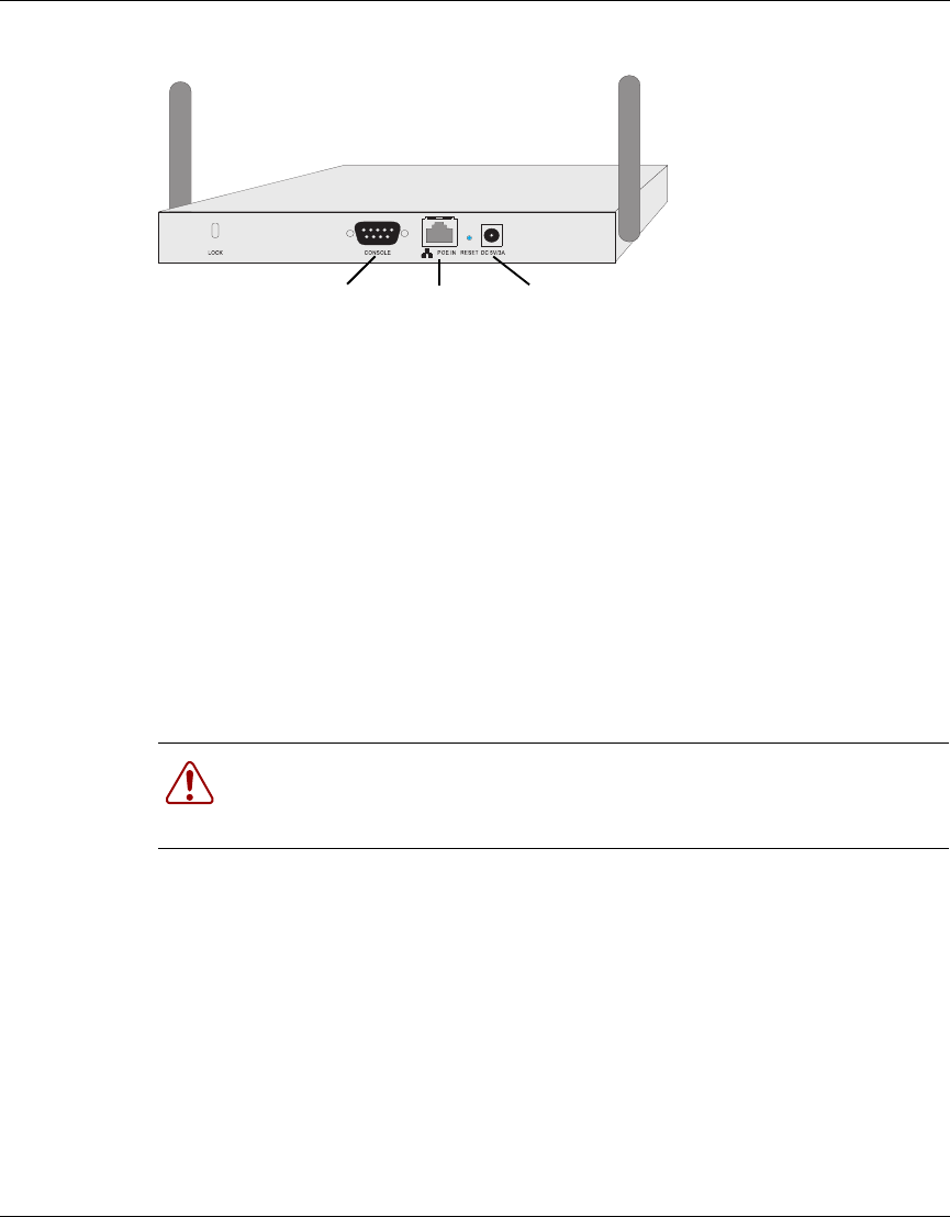
Figure 2 Rear Panel
2Connect the Console Port – Connect the console cable to the RS-232 console
port for accessing the command-line interface. (Refer to “Run Time Console
Specifications” for complete information on the CLI.) You can manage the
access point through this console connection, or the Web management
interface (refer to “System Configuration” on page 24.)
3Connect the Ethernet Cable – The Access Point 2220/2221 can be connected
to a wireline network via a 10 or 100 Mbps Ethernet connection. Connect a
Cat 5 (or higher) UTP cable between the Access Point 2220/2221 and another
network device such as a hub or switch.
4If you are not using PoE, use the separately orderable power adapter –
Connect the power adapter cable to the 5 VDC power socket on the rear panel.
Warning: Use ONLY the power adapter supplied by Nortel Networks for
this product. Otherwise, the product may be damaged. Contact your
Nortel Networks representative to order the power adapter.
5 V DC
Power Socket
RJ-45
Connector
(PoE)
Console
Port
Chapter 2 Network Configuration and Planning 21
Using the Nortel Networks Wireless LAN Access Point 2220/2221
Chapter 2
Network Configuration and Planning
The wireless solution supports a stand-alone wireless network configuration as
well as an integrated configuration with 10/100 Mbps Ethernet LANs.
The wireless network cards, adapters, access points and wireless access point can
be configured as:
• Ad hoc for departmental LANs
• Infrastructure for wireless LANs
• Infrastructure wireless LAN for roaming wireless PCs
Network Topologies
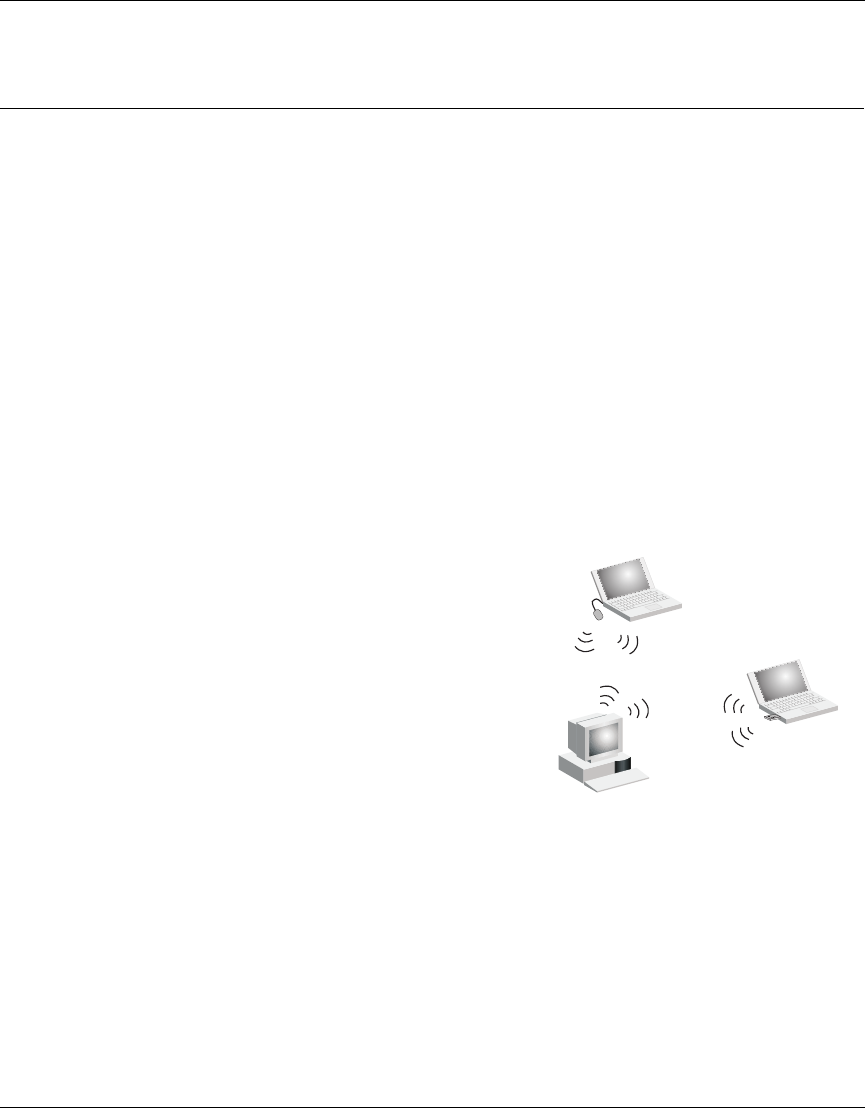
Ad Hoc Wireless LAN
(no AP or Bridge)
Ad-hoc mode is also called “peer-to-peer
mode” or “Independent Basic Service Set
(IBSS).” In ad hoc mode, devices
communicate directly with each other
without using an access point.
An ad hoc wireless LAN consists of a group
of computers, each equipped with a wireless
adapter, connected via radio signals as an
independent wireless LAN. Computers in a
specific ad hoc wireless LAN must therefore be configured to the same radio
channel. An ad hoc wireless LAN can be used for a branch office operation.
Ad Hoc Wireless LAN
Notebook with
Wireless USB Adapter
Notebook with
Wireless PC Card
PC with Wireless
PCI Adapter
22 Chapter 2 Network Configuration and Planning
214853-B
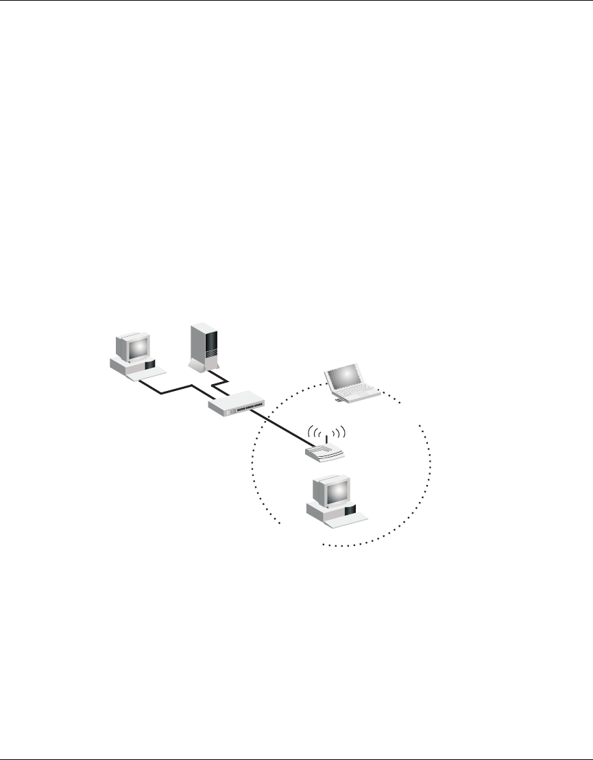
Infrastructure Wireless LAN
The access point can also provide access to a wired LAN for wireless
workstations. An integrated wired/wireless LAN is called an Infrastructure
configuration. A Basic Service Set (BSS) consists of a group of wireless PC users,
and an access point that is directly connected to the wired LAN. Each wireless PC
in this BSS can talk to any computer in its wireless group via a radio link, or
access other computers or network resources in the wired LAN infrastructure via
the access point.
The infrastructure configuration not only extends the accessibility of wireless PCs
to the wired LAN, but also increases the effective wireless transmission range for
wireless PCs by passing their signal through one or more access points.
A wireless infrastructure can be used for access to a central database, or for
connection between mobile workers, as shown in the following figure.
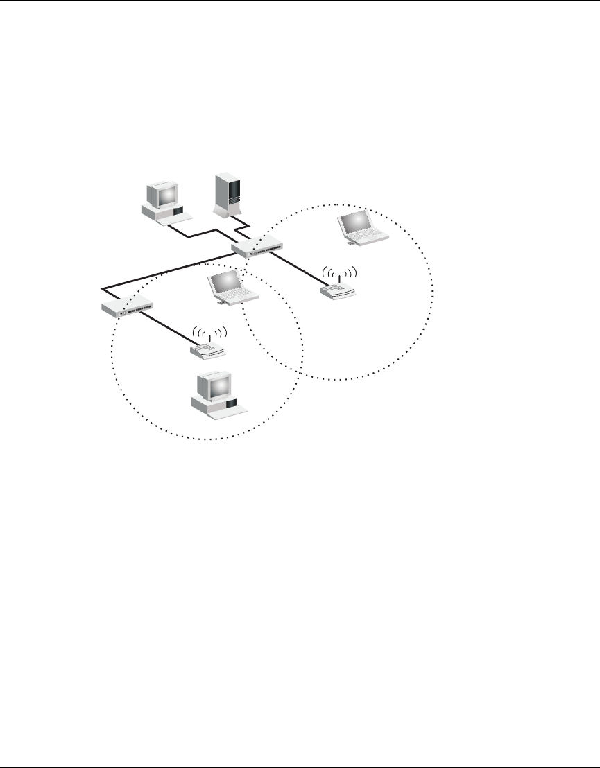
Infrastructure Wireless LAN for Roaming Wireless PCs
The Basic Service Set (BSS) is the communications domain for each wireless
access point. For wireless PCs that do not need to support roaming, set the domain
identifier (SSID) for the wireless card to the SSID of the access point to which
you want to connect. Check with your administrator for the SSID of the access
point or bridge to which he wants you to connect.
File
Server
Switch
Desktop PC
Access Point
Wired LAN Extension
to Wireless Adapters
PC with Wireless
PCI Adapter
Notebook with Wireless
PC Card Adapter
Chapter 2 Network Configuration and Planning 23
Using the Nortel Networks Wireless LAN Access Point 2220/2221
A wireless infrastructure can also support roaming for mobile workers. More than
one access point can be configured to create an Extended Service Set (ESS). By
placing the access points so that a continuous coverage area is created, wireless
users within this ESS can roam freely. All Nortel Networks Wireless LAN--Series
2200 wireless network cards and adapters and Access Point 2220/2221 wireless
access points within a specific ESS must be configured with the same SSID
.
File
Server
Switch
Desktop PC
Access Point
<BSS2>
Notebook with Wireless
PC Card Adapter
Seamless Roaming
<ESS>
Switch
Access Point
<BSS1>
PC with Wireless
PCI Adapter
Notebook with Wireless
PC Card Adapter

24 Chapter 3 System Configuration
214853-B
Chapter 3
System Configuration
The Access Point 2220/2221 can be configured by any Java-supported Web
browser including Internet Explorer 4.0 or above, or Netscape Navigator 6.0 or
above. Using the Web management interface, you may configure the Access Point
2220/2221. You can also use the command line interface (CLI) to manage the
Access Point 2220/2221.
Accessing the CLI
You access the CLI using Telnet or a direct serial connection to the unit from a
terminal or personal computer (PC). You can use any terminal or PC with a
terminal emulator as the CLI command station. If using a direct connection via the
console port, make sure the terminal has the following features:
• 9600 bits per second (b/s), 8 data bits, 1 stop bit, no parity, no flow control
• Serial terminal-emulation program
• Null modem cable and connector to match the female DB-9 connector on the
Access Point 2220/2221 console port
Note: Both 802.11a and 802.11b radios are turned off on your Nortel
Networks Wireless LAN Access Point 2220/2221. You must configure
your Access Point 2220/2221 for your country before turning on the
802.11a and 802.11b radios.
For information on country-specific configuration, refer to
Country-specific Configuration for the Nortel Networks Wireless LAN
Access Point 2220/2221 (part number 215293-B). Go to
http://support.nortelnetworks.com/, select “Wireless LAN” and then
“WLAN Access Point 2220” or “WLAN Access Point 2221”.

Chapter 3 System Configuration 25
Using the Nortel Networks Wireless LAN Access Point 2220/2221
Telnet or open the console connection to the Access Point 2220/2221.
1When you have connected to the Access Point 2220/2221, you will see the
following prompt:
Username:
2Enter:
nortel
You will see the following prompt:
Password:
3The default is no password. Press Enter.
The EXEC mode prompt appears:
Nortel Enterprise AP#
For a list of commands available from the CLI, refer to Run Time Console
Specifications (part number 215113-A).
Using the Web Management Interface
To initially manage the Access Point 2220/2221 using the web management
interface, you must configure the network settings of the computers on your
wireless LAN to use the same IP subnet as the Access Point 2220/2221. The
default network settings assuming there is no external DHCP server for this device
are:
Access Point IP Address: 192.168.168.10
Gateway IP Address: 192.168.168.254
Subnet Mask: 255.255.255.0
The IP address of the connected client PC from which system configuration is to
be performed should be 192.168.168.x (where x means 1–9, 11–253).
26 Chapter 3 System Configuration
214853-B
If DHCP is enabled, (default setting is “Enable,” page 48) and a DHCP server is
located on the network, then the access point will automatically be assigned an IP
address when booted.
To access the Access Point 2220/2221’s management interface, enter the IP
address of the device in your Web browser:
http://192.168.168.10
The Web management window will appear.
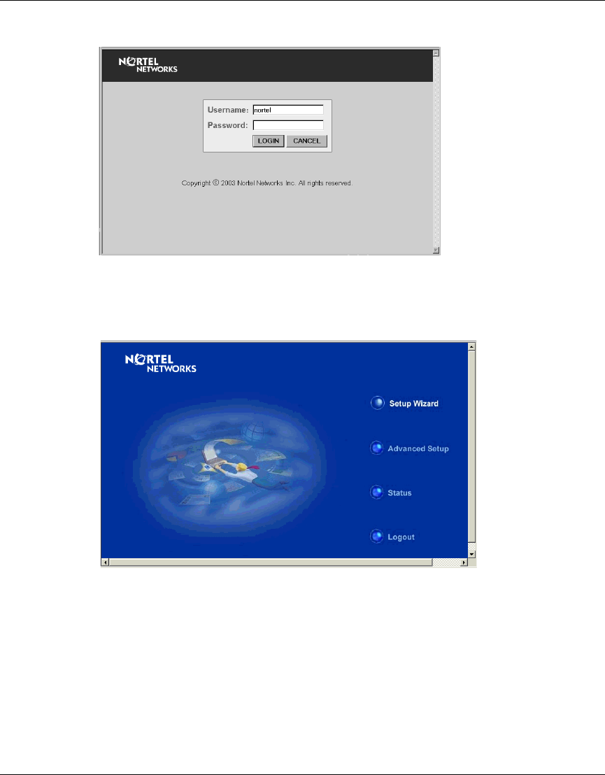
Setup Wizard
1To access the management interface (Figure 3), enter the username “nortel”
and click “LOGIN.”
Note: Both 802.11a and 802.11b radios are turned off on your Nortel
Networks Wireless LAN Access Point 2220/2221. You must configure
your Access Point 2220 for your country before turning on the 802.11a
and 802.11b radios.
For information on country-specific configuration, refer to
Country-specific Configuration for the Nortel Networks Wireless LAN
Access Point 2220/2221 (part number 215293-B). Go to
http://support.nortelnetworks.com/, select “Wireless LAN” and then
“WLAN Access Point 2220” or “WLAN Access Point 2221”.
Note: There is no password by default.
28 Chapter 3 System Configuration
214853-B
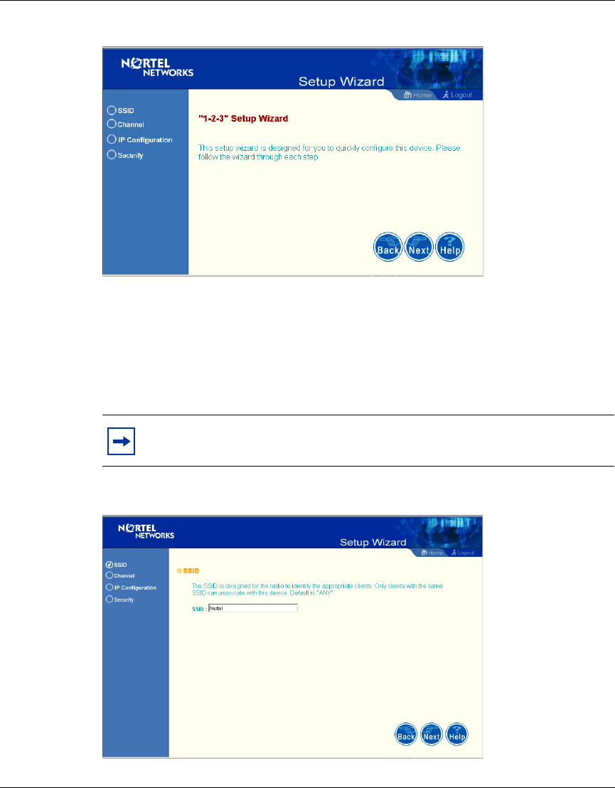
Figure 5 Setup Wizard screen
4Click the “Next” button to start basic configuration (Figure 6).
SSID – The Service Set ID. This should be set to the same value as other
wireless devices in your network.
(Default: Nortel)
Figure 6 SSID screen
Note: The SSID is case sensitive and can consist of up to 32
alphanumeric characters.
Chapter 3 System Configuration 29
Using the Nortel Networks Wireless LAN Access Point 2220/2221
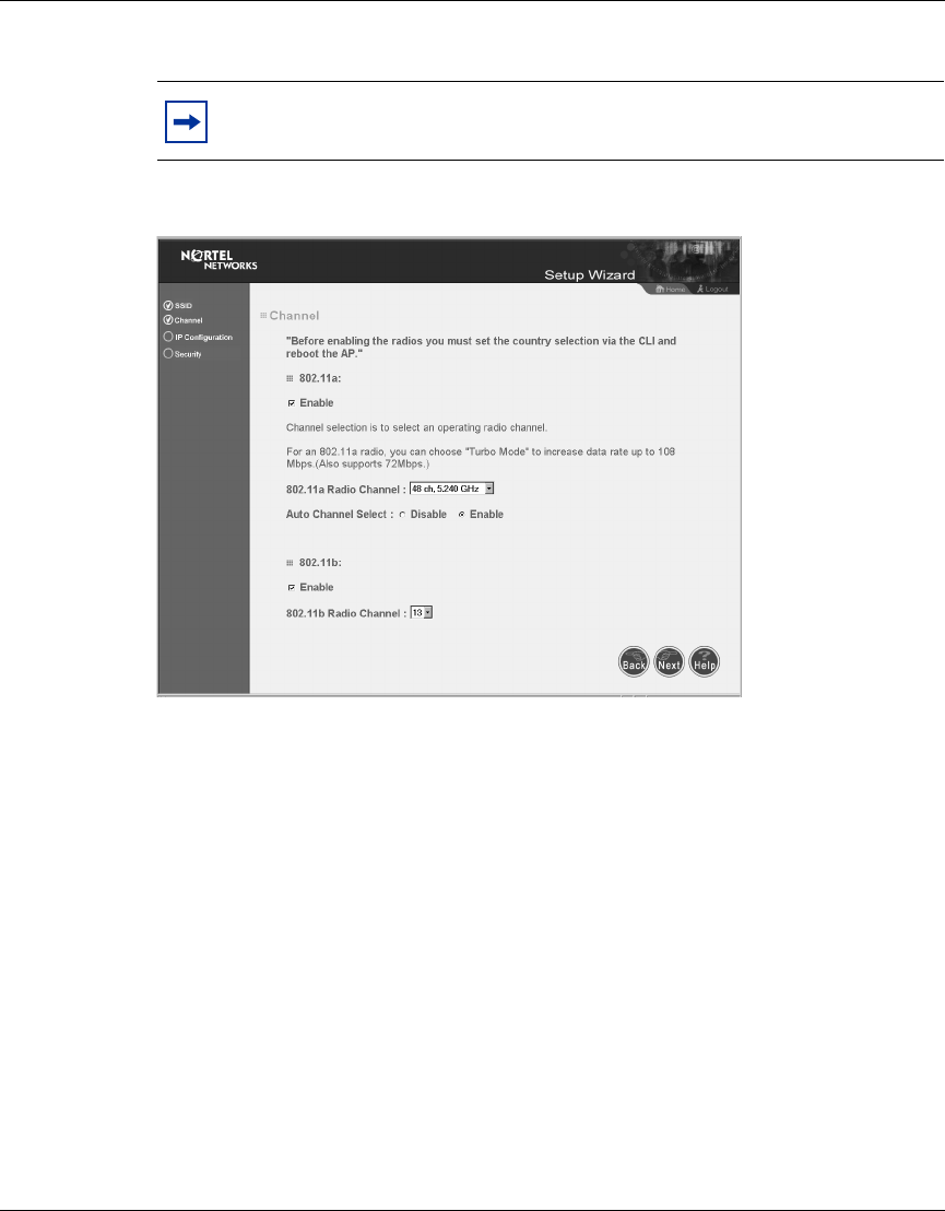
Channel
802.11a
Enable: Check this box to enable the 802.11a radio of your Access Point 2220/
2221. By default the radio is not enabled.
802.11a Turbo Mode: When turbo mode is enabled, the Access Point 2220/2221
operates with a data rate of up to 108 Mbps. By default, turbo mode is disabled,
and the Access Point 2220/2221 operates at a data rate of up to 54 Mbps. When
you select Turbo Mode, the Access Point 2220/2221 uses two adjacent 802.11a
channels to achieve the bandwidth.
802.11a Radio Channel: If auto channel select is not enabled, this option allows a
specific channel to be selected.
Auto Channel Select: Selecting “Enable” allows for automatic radio channel
detection. Automatic radio channel detection only occurs at boot-up. (Default:
“Enable”)
802.11b
Enable: Check this box to enable the 802.11b radio of your Access Point 2220/
2221. By default the radio is not enabled.
Note: Both 802.11a and 802.11b radios are turned off on your Nortel
Networks Wireless LAN Access Point 2220/2221. You must configure
your Access Point 2220/2221 for your country before turning on the
802.11a and 802.11b radios.
For information on country-specific configuration, refer to
Country-specific Configuration for the Nortel Networks Wireless LAN
Access Point 2220/2221 (part number 215293-B). Go to
http://support.nortelnetworks.com/, select “Wireless LAN” and then
“WLAN Access Point 2220” or WLAN Access Point 2221”.
Note: The use of Turbo Mode is not allowed in all regions. Before
enabling Turbo Mode, verify that Turbo Mode is allowed under your
current local regulations.
30 Chapter 3 System Configuration
214853-B
802.11b: Set the operating radio channel number (Default: channel 11)
Figure 7 Channel screen
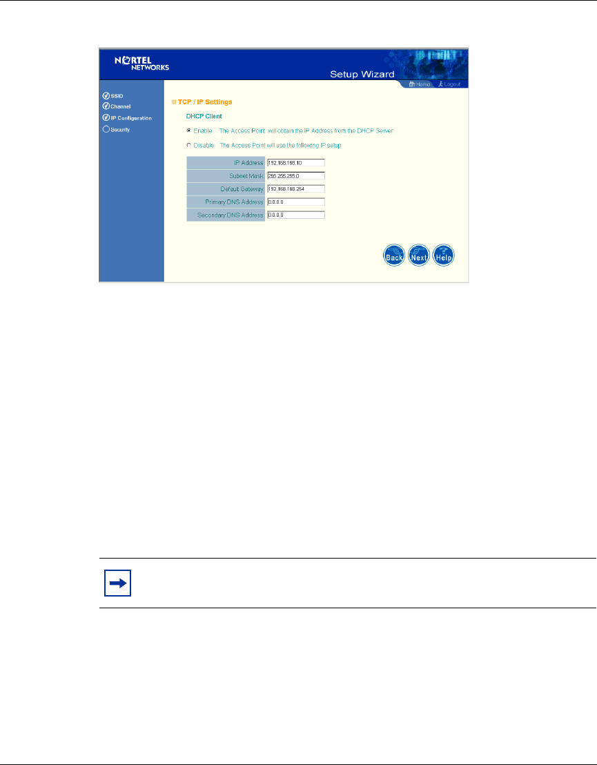
IP Configuration
DHCP Client: With DHCP (Dynamic Host Configuration Protocol) Client
enabled, the IP address, subnet mask, default gateway, and DNS address can be
dynamically assigned to the access point by an external network DHCP server on
the network. This device implements a DHCP client but not a DHCP server.
(Default: Enable)
If DHCP Client is not enabled, you must enter the IP address, subnet mask,
default gateway, and one or more DNS (Domain Name Servers) addresses
(Figure 8).
Note: Available channel settings are limited by local regulations which
determine which channels are available (Figure 7).
Chapter 3 System Configuration 31
Using the Nortel Networks Wireless LAN Access Point 2220/2221
Figure 8 TCP/IP Settings screen
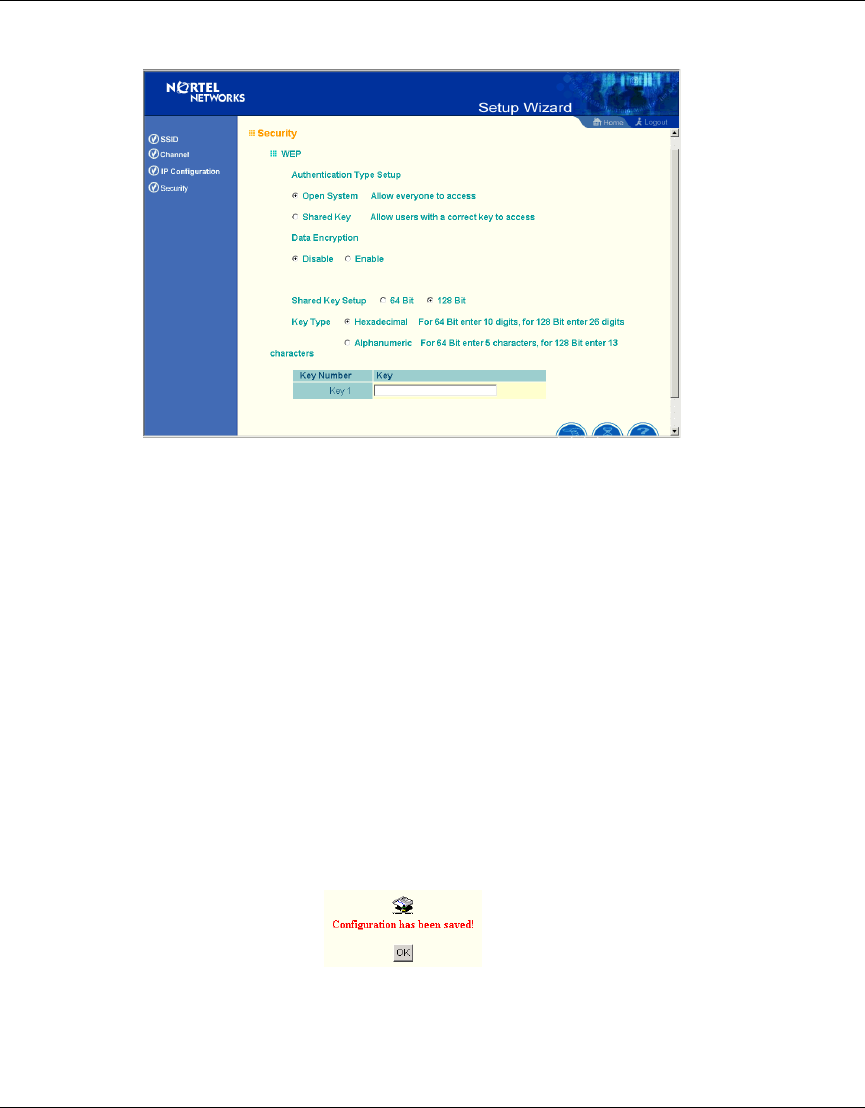
Security
WEP – Wired Equivalent Privacy (WEP) is implemented in this device to prevent
unauthorized access to your wireless network (Figure 9).
Authentication Type: Click on the “Shared Key” radio button to start filtering the
frames with the addresses defined in the “Shared Key Setup” field. Enabling the
shared key gives the option to encrypt the data. (Default: Open System)
Shared Key Setup: For more secure data transmission, check the “Enable” radio
button in the “Data Encryption” field. Then select one shared key size and the key
number. (WEP Default: Disable)
Note: If you select Shared Key, you must enable Data Encryption.
32 Chapter 3 System Configuration
214853-B
Figure 9 Security screen
The Access Point 2220/2221 supports “Shared Key” encryption with key lengths
of the standard 64-bit and industry standard 128-bit. The bit key can be in
alphanumeric characters, or hexadecimal numerals (0-9, A-F, e.g., D7 0A 9C 7F
E5.) All wireless devices must have the same Key ID values to communicate.
64-Bit Manual Entry
Key 1-4 - Each Key ID contains 10 HEX digits, or 5 alphanumeric characters.
128-Bit Manual Entry
Key ID contains 26 HEX digits, or 13 alphanumeric characters.
1Click “Finish.”
2Click the “OK” button to restart the access point.
Chapter 3 System Configuration 33
Using the Nortel Networks Wireless LAN Access Point 2220/2221
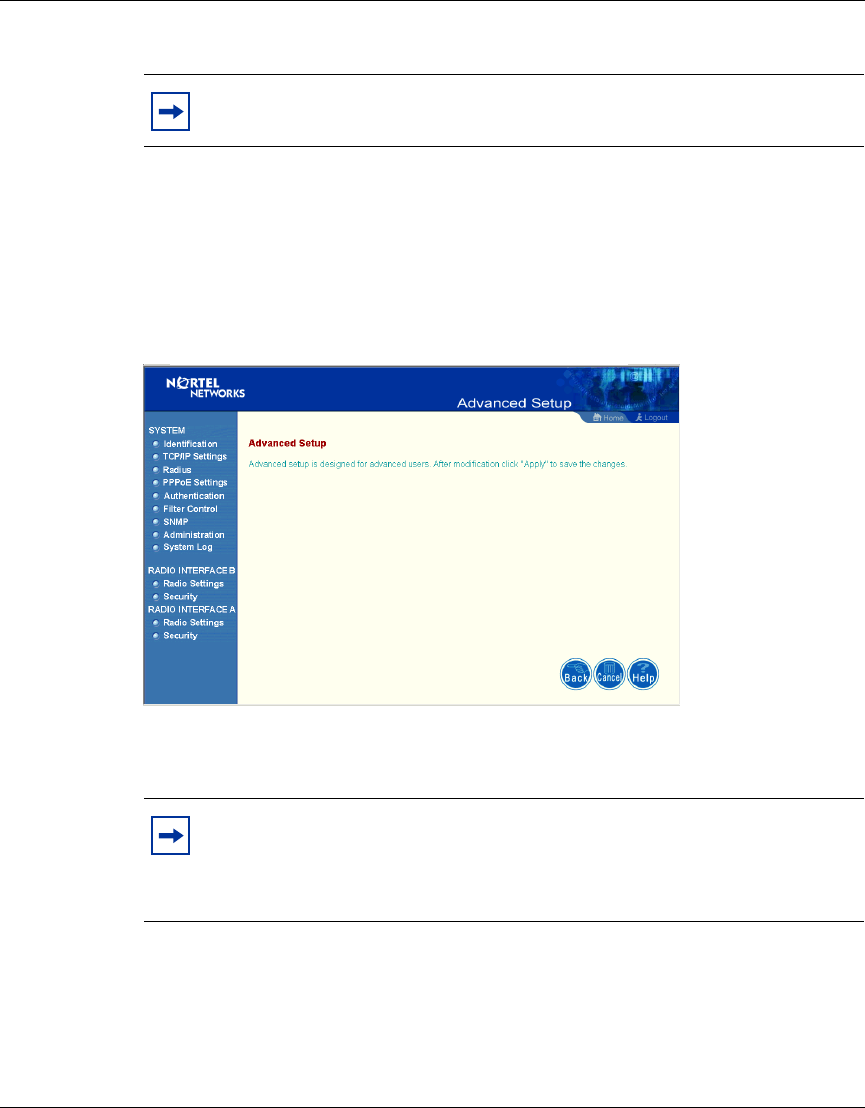
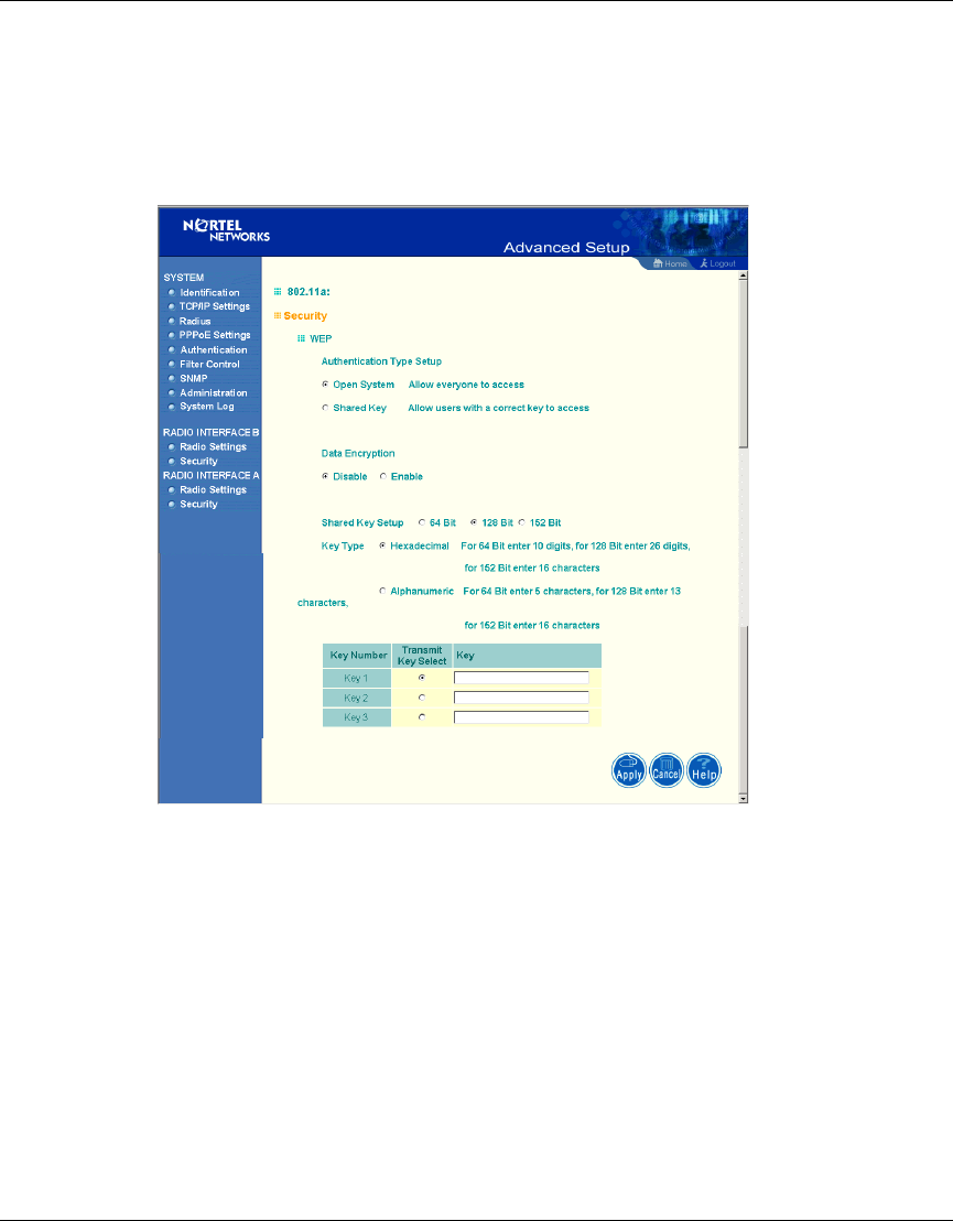
Advanced Setup
Click “Advanced Setup” on the Home page to open the Advanced Setup page.
(Figure 10).
Figure 10 Advanced Setup screen
Note: You must use the Advanced screens to do 152-bit encryption,
which is available only on 802.11a.
Note: The “Advanced Setup” screen allows you to view and change the
current configuration of the access point. After modifying the
configuration parameters, you must click on the “Apply” button to save
the changes.
34 Chapter 3 System Configuration
214853-B
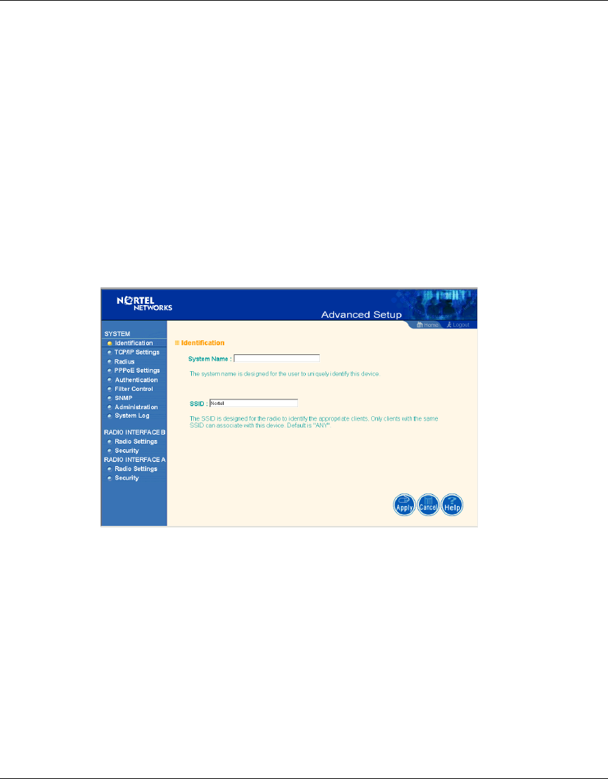
System
Identification
System Name: You can easily identify the access point by providing a descriptive
name. Enter a maximum of 32 characters in the System Name field (Figure 11).
SSID: The SSID (Service Set Identification) is the name of a Basic Service Set
(BSS) provided by an access point. Clients that want to connect to the wireless
network via an access point must set their SSIDs to the same as that of the access
point. (SSID Default: Nortel). (The default system location is the MAC address.)
Figure 11 Identification screen
Chapter 3 System Configuration 35
Using the Nortel Networks Wireless LAN Access Point 2220/2221
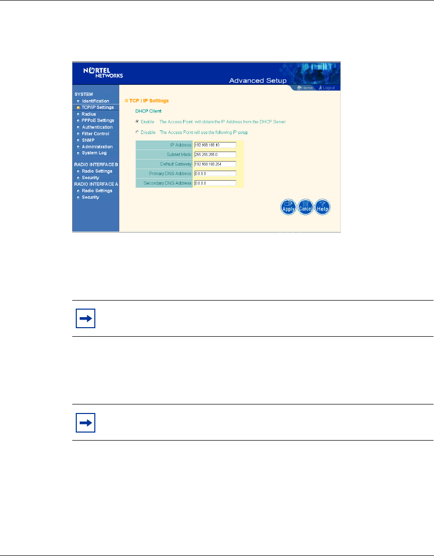
TCP / IP Settings
Figure 12 TCP/IP Settings screen
DHCP Client: With DHCP (Dynamic Host Configuration Protocol) Client
enabled, the IP address, subnet mask and default gateway can be dynamically
assigned to the access point by the network DHCP server. (Default: Enable)
If DHCP Client is not enabled, you must enter the IP address, subnet mask,
default gateway, and one or more DNS (Domain Name Servers) addresses. Enter
those addresses on this screen (Figure 12).
Note: You must disable DHCP for the manual TCP/IP addresses to be
accepted (Figure 12).
Note: If there is no DHCP server on your network, then the access point
will automatically start up with its default IP address, 192.168.168.10.
36 Chapter 3 System Configuration
214853-B
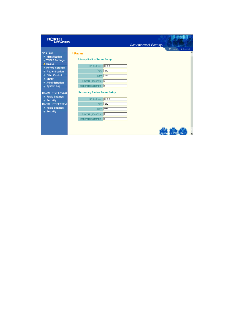
RADIUS
Figure 13 RADIUS screen
Remote Authentication Dial-in User Service (RADIUS) is a logon authentication
protocol that uses software running on a central server to control access to
RADIUS-compliant devices on the network. It allows a wireless access point to
send the connection parameters to a RADIUS server. Enter the required
parameters as shown on the screen, which includes the RADIUS server IP
address, controlled port number, per-client unicast session key, timeout value (in
seconds), and retransmit attempts number (Figure 13).
The following RADIUS servers are supported by the Access Point 2220/2221:
• Microsoft IAS: Windows 2000 Server Build 2195 Service Pack 2: TLS
• Funk Odyssey Server (Version 1.0): TTLS, TLS
IP Address – Address of authentication server. (Default: 0.0.0.0)
Port – Network (UDP) port of authentication server used for authentication
messages (Range: 1-65535; Default: 1812)
Key – Encryption key (password) used to authenticate logon access for client. Do
not use blank spaces in the string. (Maximum length: 255 characters)
Chapter 3 System Configuration 37
Using the Nortel Networks Wireless LAN Access Point 2220/2221
Timeout – The number of seconds the access point waits for a reply from the
RADIUS server before it resends the request. (Range: 1-60; Default: 5)
Retransmit attempts – Number of times the access point will try to authenticate
logon access via the authentication server. (Range: 1-30; Default: 3)
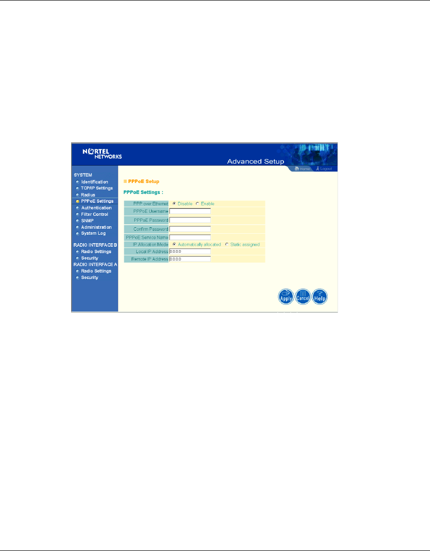
PPPoE Settings
Figure 14 PPPoE Setup screen
Enter the PPPoE user name and password assigned by your Service Provider
(Figure 14). The Service Name is normally optional, but may be required by some
service providers.
Some xDSL Internet Service Providers may assign a fixed (static) IP address. If
you have been provided with this information, click on the “Static assigned” for
the “IP Allocation Mode,” and enter the assigned “Local IP Address” and
“Remote IP addresses.”
38 Chapter 3 System Configuration
214853-B
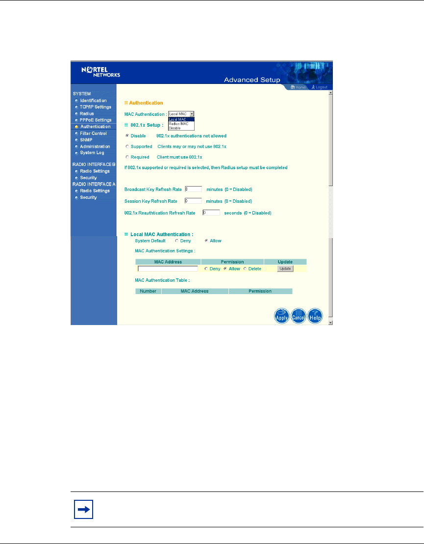
Authentication
Figure 15 Authentication screen
Management access will be checked against the authentication database stored on
the access point (Figure 15). If a remote authentication server is used, you must
specify the authentication sequence and the corresponding parameters (see
“RADIUS” on page 36) for the remote authentication protocol.
MAC Authentication (Default: Local MAC)
Selecting the MAC authentication allows you to define access permission and
precedence. For Local MAC Authentication go to page 39. For RADIUS MAC
Authentication see the following page.
Note: Be sure to set up the RADIUS MAC authentication for the client
on the Radius server before using the RADIUS MAC service.

Chapter 3 System Configuration 39
Using the Nortel Networks Wireless LAN Access Point 2220/2221
802.1x Setup
Click the “Supported” or “Required” radio button on the 802.1x Setup field when
using the Radius MAC authentication.
Local MAC Authentication
Client computers can be filtered using the unique MAC address of their IEEE
802.11 network card. To secure an access point using local MAC address filtering,
you must enter a list of allowed/denied client MAC addresses into the filtering
table.
Table 2 802.1x Setup
Field Defaults Description
Broadcast Key
Refresh Rate 0 (in
minutes) Defines how long the radius server will
refresh the primary broadcast key
Session Key
Refresh Rate 0 (in
minutes) Defines how long the radius server will
dynamically re-assign a session key to a
connected client station.
802.1x
Reauthentication
Refresh Rate
0 (in
seconds) Defines how long the radius server will
dynamically re-assign session keys to
the all connected client stations.
Table 3 Local MAC Authentication
Parameter Description
System Default Define the default filtering setting as “Deny”
or “Allow.”
MAC Address Manually type in the MAC address of a
client for the access control
Permissions Allows/Denies access of devices matching
a specified source IP address in the list to
connect to the access point.
Update Click the “Update” button to refresh the
settings.
40 Chapter 3 System Configuration
214853-B
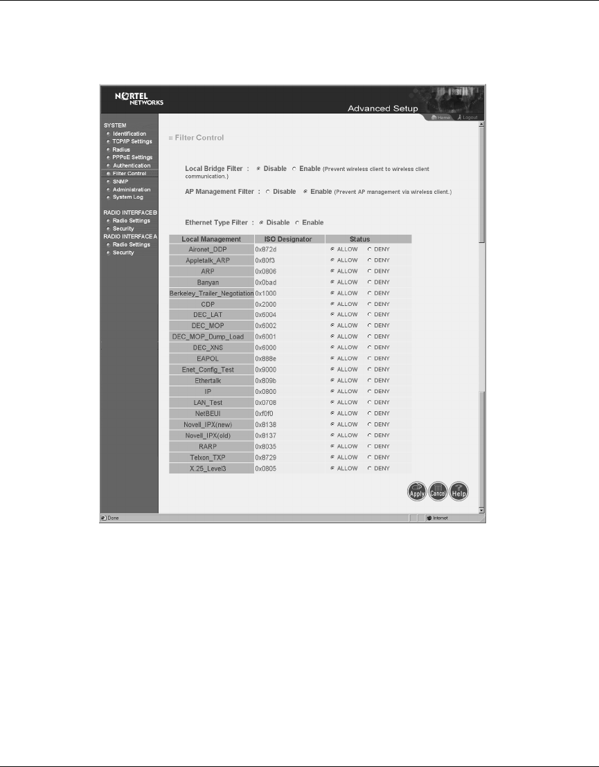
Filter Control
Figure 16 Filter Control screen
Local Bridge Filter
Using this filter function (Figure 16) prevents direct node-to-node connection
through the Access Point 2220/2221, for a more secure wireless network. The
Local Bridge Filter does not restrict ad hoc connections between clients. (Default:
Disable)
AP Management Filter
The administration management can be protected with AP Management Filter.
(Default: Enable)
Chapter 3 System Configuration 41
Using the Nortel Networks Wireless LAN Access Point 2220/2221
Ethernet Type Filter
Use the “Ethernet Type Filter” table to filter out Ethernet packet frames matching
Ethernet protocol type. (Default: Disable)
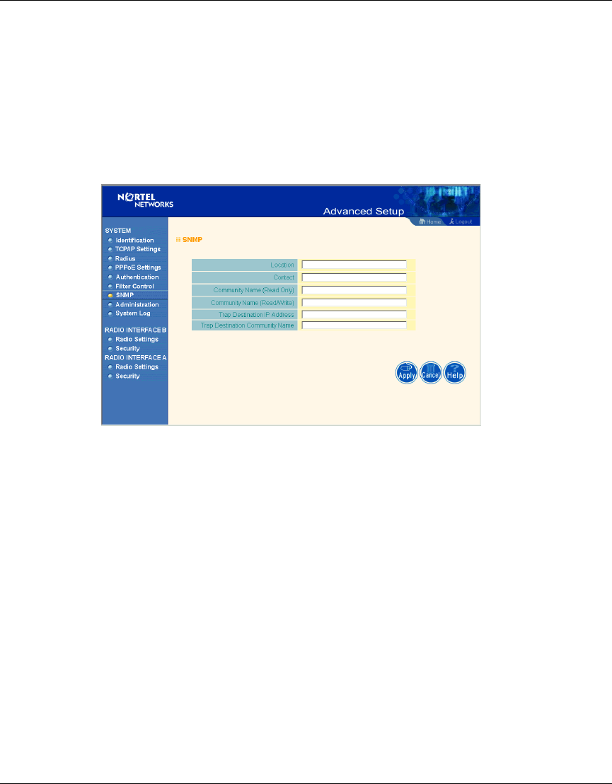
SNMP
Figure 17 SNMP screen
Use this screen to display and enter a community string for the Simple Network
Management Protocol (SNMP). To communicate with the access point, the SNMP
agent must first be enabled, and the Network Management Station must submit a
valid community string for authentication (Figure 17).
Location - Specifies the access point location
Contact - Set the system location string, that describes the system location.
(Maximum length: 255 characters)
Community Name (Read Only) - Specifies a community string with read-only
access. Authorized management stations are only able to retrieve MIB objects.
(Maximum length: 23 characters)
42 Chapter 3 System Configuration
214853-B
Community Name (Read/Write) - Specifies a community string with read-write
access. Authorized management stations are able to both retrieve and modify MIB
objects. (Maximum length: 23 characters)
Trap Destination IP Address - Fill in the IP address box for a trap manager that
will receive these messages.
Trap Destination Community Name - Fill in the community string box for a trap
manager that will receive these messages. (Maximum length: 23 characters)
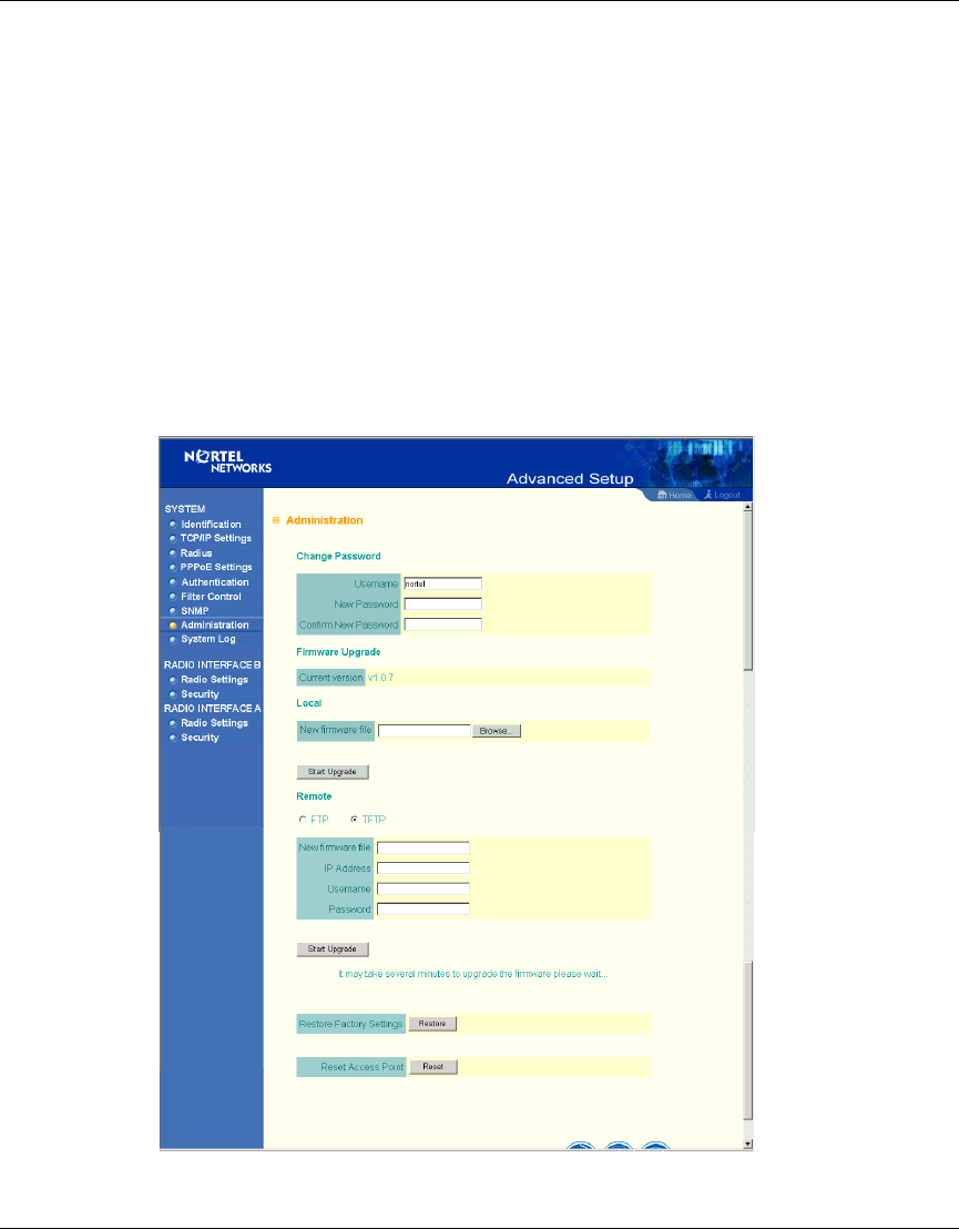
Administration
Figure 18 Administration screen
Chapter 3 System Configuration 43
Using the Nortel Networks Wireless LAN Access Point 2220/2221
Change Password
Use this section to change the password on the access point (Figure 18).
Firmware Upgrade
Local - Click “Browse” to locate the downloaded firmware file and click “Start
Upgrade” to start the upgrade process.
Remote - Select FTP or TFTP, and enter firmware file name, the host IP address,
user name, and password. (You need your user name and password only with the
FTP.) Click “Start Upgrade” to start the upgrade process.
For latest firmware version information, go to the Nortel Networks customer
support web site at: http://support.nortelnetworks.com/, select “Wireless LAN”
and then “WLAN Access Point 2220” or “WLAN Access Point 2221” and then
“Software.”
Restore Factory Settings
Click the “Restore” button to load the factory default configuration and reboot this
device. Note that all user configured information will be lost. You will also have to
re-enter the default user name (nortel) to regain management access to this device.
Reset Access Point
Clicking on the “Reset” button to perform a hardware reset of the access point.
Note: You must disable the radios prior to upgrading the Access Point
2220/2221 or the upgrade may not occur.
Note: Although current configurations will not be changed, you must
reset the time. (The default time setting is January 1 at midnight.)
44 Chapter 3 System Configuration
214853-B
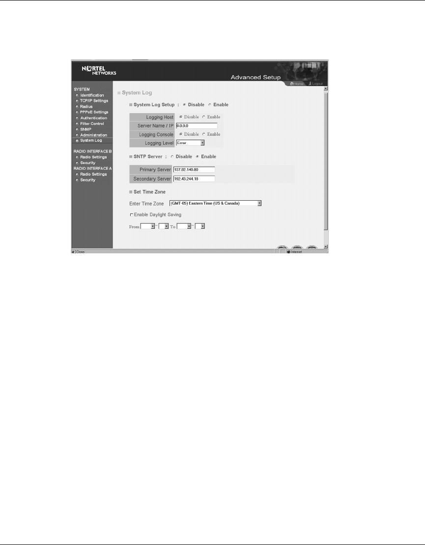
System Log
Figure 19 System Log screen
The System Log Setup (Figure 19) allows you to setup a log server with various
logging level (as shown on the above screen). (Default: Disable)
SNTP Server
Allows you to enter Simple Network Time Protocol (SNTP) Server information
for a primary and secondary SNTP Server. (Default: Enable) You may also set
your time zone and daylight savings information (as shown on the above screen).
Chapter 3 System Configuration 45
Using the Nortel Networks Wireless LAN Access Point 2220/2221
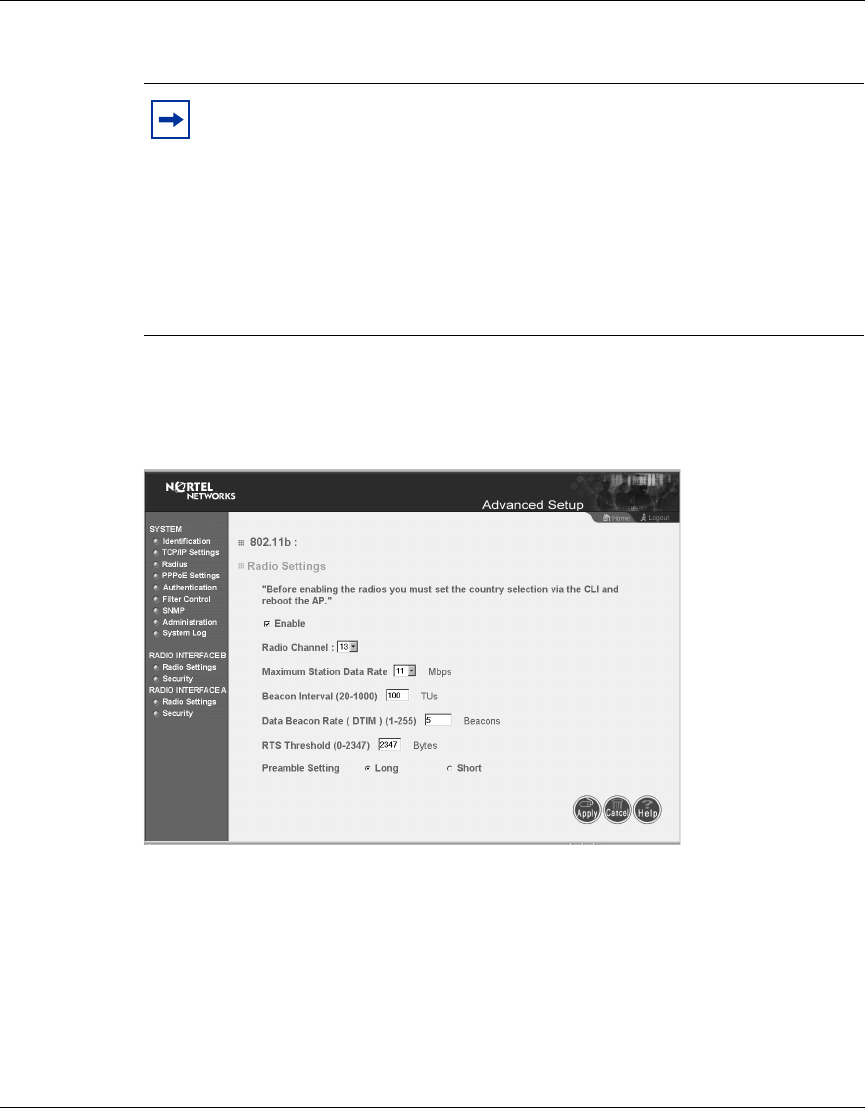
Radio Interface B
Radio Settings
Figure 20 Radio Settings screen
Enable
Check this box to enable the 802.11b radio of your Access Point 2220/2221. By
default the radio is not enabled.
Note: Both 802.11a and 802.11b radios are turned off on your Nortel
Networks Wireless LAN Access Point 2220/2221. You must configure
your Access Point 2220/2221 for your country before turning on the
802.11a and 802.11b radios.
For information on country-specific configuration, refer to
Country-specific Configuration for the Nortel Networks Wireless LAN
Access Point 2220/2221 (part number 215293-B). Go to
http://support.nortelnetworks.com/, select “Wireless LAN” and then
“WLAN Access Point 2220” or “WLAN Access Point 2221”.
46 Chapter 3 System Configuration
214853-B
Radio Channel
The radio channel (Figure 20) is the channel number used for communication
between the access point and its BSS. (Default: channel 11)
Maximum Station Data Rate
Select the appropriate data rate from the drop-down list for the data transfer speed
running on your network. (Default: 11 Mbps)
Beacon Interval (20-1000)
Sets the beacon signal interval. The beacon signals allow the wireless devices to
maintain contact with each other. They may also carry power-management
information. (Default: 100 TU)
DTIM Period (1-16384)
Sets the Delivery Traffic Indication Message (DTIM) packet interval value. The
DTIM informs the client that the access point has broadcast and multicast traffic
to send. This parameter is necessary to wake up stations that are using Power Save
mode.
Note: The available channel settings are limited by local regulations,
which determine the number of channels that are available. (For more
information specific to each country’s configuration, refer to
Country-specific Configuration for the Nortel Networks Wireless LAN
Access Point 2220/2221 (part number 215293-B). Go to
http://support.nortelnetworks.com/, select “Wireless LAN” and then
“WLAN Access Point 2220” or “WLAN Access Point 2221”.
Note: Nortel Networks recommends you do not change any default
settings.

Chapter 3 System Configuration 47
Using the Nortel Networks Wireless LAN Access Point 2220/2221
The DTIM is the interval between two synchronous frames with broadcast
information. If you set the value to 2, the access point saves broadcast and
multicast packets and forwards them after every second beacon. Having smaller
DTIM intervals delivers broadcast and multicast frames in a more timely manner;
however, by causing stations in Power Save mode to wake up more often, smaller
DTIM intervals drain power faster. Conversely, having higher DTIM values delays
the transmission of broadcast and multicast frames, but the larger DTIM intervals
reduces the power used by stations in Power Save mode. (Default: 5 Beacons)
RTS Threshold (0-2347)
Set the RTS (Request to Send) frame length. You may configure the access point
to initiate an RTS frame sequence always, never, or only on frames longer than a
specified length. If the packet size is smaller than the preset RTS threshold size,
the RTS/CTS mechanism will NOT be enabled
When the RTS/CTS mechanism is enabled, the access point sends Request to
Send (RTS) frames to a particular receiving station to negotiate the sending of a
data frame. After receiving an RTS frame, the station sends a CTS (Clear to Send)
frame to acknowledge the right of the sending station to send data frames. The
access points contending for the media may not be aware of each other. The RTS/
CTS mechanism allows other access points in the vicinity to see the CTS and
become quiet while the first access point transmits frames. (This mechanism
should be enabled on both the clients and the access points.) (Default: 2347)
Preamble Setting
The access points and client card drivers have a radio setting for RF Preamble. Set
it to short for better throughput; although this setting may cause interoperability
issues with some NICs. (Default: Long)
48 Chapter 3 System Configuration
214853-B
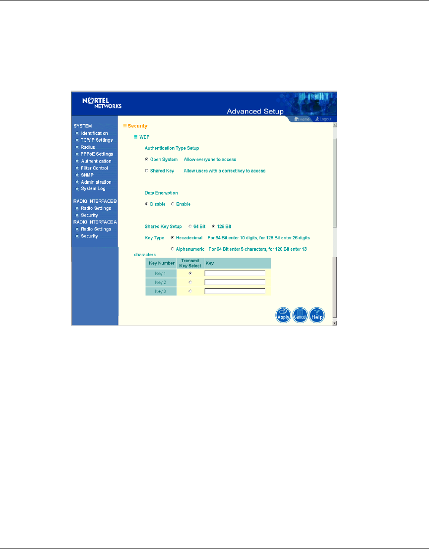
Security
WEP (Wired Equivalent Privacy)
Figure 21 Security screen
WEP is implemented in this device to prevent unauthorized access to your
wireless network (Figure 21). The WEP setting must be the same on each client in
your wireless network.
Authentication Type Setup
You may choose either “Open System” or “Shared Key.”
(Default: Open System)
If Shared Key is enabled, WEP should be enabled and at least one shared key
should be defined.
Chapter 3 System Configuration 49
Using the Nortel Networks Wireless LAN Access Point 2220/2221
Data Encryption
You may choose “Enable” to enhance your network security with WEP data
encryption
(Default: Disable)
If Shared Key is enabled, WEP should be enabled and at least one shared key
should be defined.
Standard Key Setup (WEP Default: 128)
Default Shared Key – Choose the Shared Key that has the encryption string you
prefer (Key 1-3).
The access point supports “Shared Key” encryption with key lengths of the
standard 64-bit and industry standard 128-bit. The bit key can be in alphanumeric
characters, or hexadecimal numerals (0-9, A-F, e.g., D7 0A 9C 7F E5.)
64-Bit Manual Entry
Key 1-3 - Each Key ID contains 10 HEX digits, or 5 alphanumeric characters.
128-Bit Manual Entry
Key ID contains 26 HEX digits, or 13 alphanumeric characters.
1Select a unique key (1-3)
2Enter the encryption key and select the key size.
3Be sure to click the “Apply” button on the bottom of the page to make the
settings take effect.
Note: All wireless devices must have the same Key ID values to
communicate.
Note: The 152-bit encryption is only available with the 802.11a Radio.
50 Chapter 3 System Configuration
214853-B
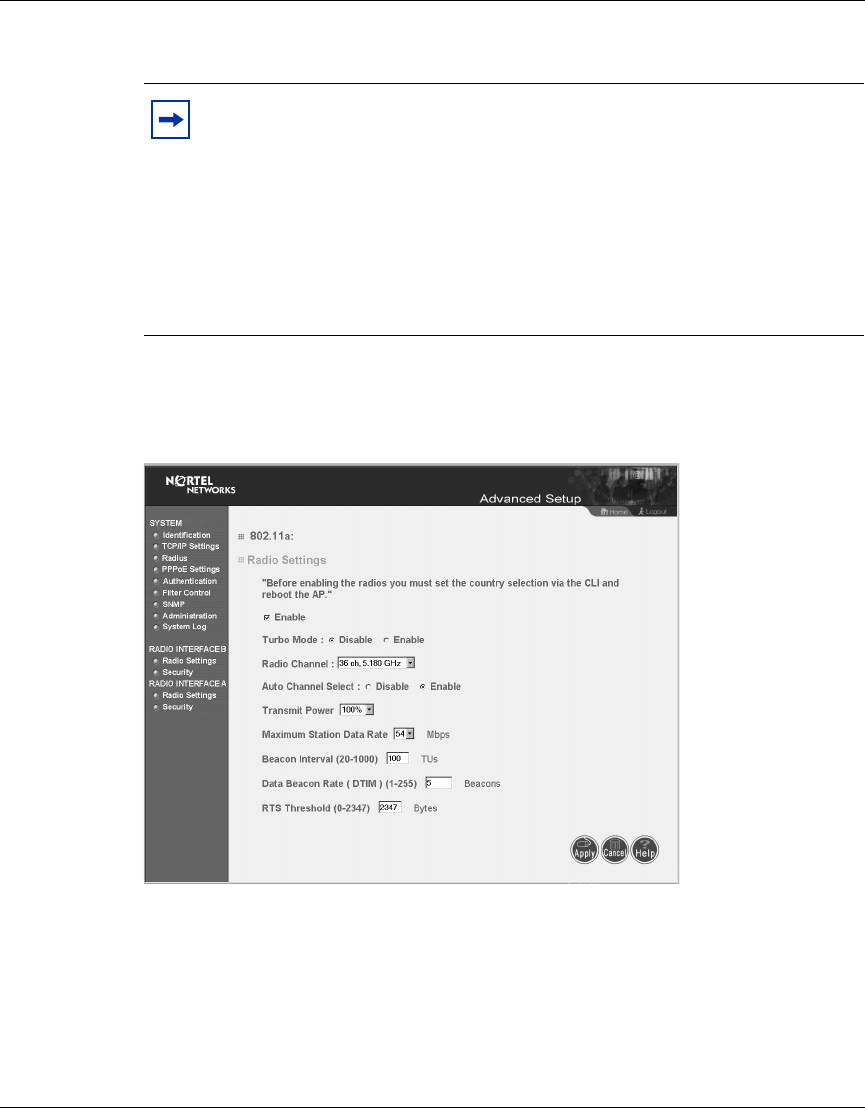
Radio Interface A
Radio Settings
Figure 22 Radio Settings screen
Enable
Check this box to enable the 802.11a radio of your Access Point 2220/2221. By
default the radio is not enabled.
Note: Both 802.11a and 802.11b radios are turned off on your Nortel
Networks Wireless LAN Access Point 2220/2221. You must configure
your Access Point 2220/2221 for your country before turning on the
802.11a and 802.11b radios.
For information on country-specific configuration, refer to
Country-specific Configuration for the Nortel Networks Wireless LAN
Access Point 2220/2221 (part number 215293-B). Go to
http://support.nortelnetworks.com/, select “Wireless LAN” and then
“WLAN Access Point 2220” or “WLAN Access Point 2221”.
Chapter 3 System Configuration 51
Using the Nortel Networks Wireless LAN Access Point 2220/2221
Turbo Mode
You may either “Enable” or “Disable” the “Turbo Mode.”
(Default: Disable)
“Turbo Mode” is an enhanced wireless LAN operating mode (not regulated in the
standard IEEE 802.11a) that can provide a higher data rate. The “Normal Mode”
of the 802.11a access point provides connections up to 54 Mbps. Enabling “Turbo
Mode” on the 802.11a access point allows the access point to provide connections
up to 108 Mbps (Figure 22). When you select Turbo Mode, the Access Point
2220/2221 uses two adjacent 802.11a channels to achieve the bandwidth.
Radio Channel
The radio channel through which the access point communicates to PCs in its
BSS. Note that the client channel for wireless users is automatically set to the
same as that used by the access point to which it is linked.
Auto Channel Select
Selecting “Enable” allows for automatic radio channel detection. Automatic radio
channel detection only occurs at boot-up.
(Default: “Enable”)
Note: The use of Turbo Mode is not allowed in all regions. Before
enabling Turbo Mode, verify that Turbo Mode is allowed under your
current local regulations.
Note: The available channel settings are limited by local regulations,
which determine the number of channels that are available. (For more
information specific to each country’s configuration, refer to
Country-specific Configuration for the Nortel Networks Wireless LAN
Access Point 2220/2221 (part number 215293-B). Go to
http://support.nortelnetworks.com/, select “Wireless LAN” and then
“WLAN Access Point 2220” or “WLAN Access Point 2221”.
52 Chapter 3 System Configuration
214853-B
Transmit Power
Set the signal strength transmitted from the access point. The longer the
transmission distance, the higher the transmission power required. (Default:
100%)
Maximum Station Data Rate
Select the appropriate data rate from the drop-down list for the data transfer speed
running on your network. (Default: 54 Mbps)
Beacon Interval (20-1000)
Sets the beacon signal interval. The beacon signals allow the wireless devices to
maintain contact with each other. They may also carry power-management
information. (Default: 100 TU)
DTIM Period (1-16384)
Sets the Delivery Traffic Indication Message (DTIM) packet interval value. The
DTIM informs the client that the access point has broadcast and multicast traffic
to send. This parameter is necessary to wake up stations that are using Power Save
mode.
The DTIM is the interval between two synchronous frames with broadcast
information. If you set the value to 2, the access point saves broadcast and
multicast packets and forwards them after every second beacon. Having smaller
DTIM intervals delivers broadcast and multicast frames in a more timely manner;
however, by causing stations in Power Save mode to wake up more often, smaller
DTIM intervals drain power faster. Conversely, having higher DTIM values delays
the transmission of broadcast and multicast frames, but the larger DTIM intervals
reduces the power used by stations in Power Save mode. (Default: 5 Beacons)
Note: Nortel Networks recommends that you do not change any default
settings.

Chapter 3 System Configuration 53
Using the Nortel Networks Wireless LAN Access Point 2220/2221
RTS Threshold (0-2347)
Set the RTS (Request to Send) frame length. You may configure the access point
to initiate an RTS frame sequence always, never, or only on frames longer than a
specified length. If the packet size is smaller than the preset RTS threshold size,
the RTS/CTS mechanism will NOT be enabled
When the RTS/CTS mechanism is enabled, the access point sends Request to
Send (RTS) frames to a particular receiving station to negotiate the sending of a
data frame. After receiving an RTS frame, the station sends a CTS (Clear to Send)
frame to acknowledge the right of the sending station to send data frames. The
access points contending for the media may not be aware of each other. The RTS/
CTS mechanism allows other access points in the vicinity to see the CTS and
become quiet while the first access point transmits frames. (This mechanism
should be enabled on both the clients and the access points.) (Default: 2347)
54 Chapter 3 System Configuration
214853-B
Security
WEP (Wired Equivalent Privacy)
Figure 23 Security screen
Authentication Type Setup
You may choose either “Open System” or “Shared Key.”
(Default: Open System)
If Shared Key is enabled, WEP is automatically enabled and at least one shared
key must be defined (Figure 23).

Chapter 3 System Configuration 55
Using the Nortel Networks Wireless LAN Access Point 2220/2221
Data Encryption
You may choose “Enable” to enhance your network security with WEP data
encryption
(Default: Disable)
If Shared Key is enabled, WEP is automatically enabled and at least one shared
key must be defined.
Standard Key Setup (WEP Default: 128)
Default Shared Key – Choose the Shared Key that has the encryption string you
prefer (Key 1-3).
The access point supports “Shared Key” encryption with key lengths from the
standard 64-bit, industry standard 128-bit, to the extended 152-bit. The bit key can
be in alphanumeric characters, or hexadecimal numerals (0-9, A-F, e.g., D7 0A 9C
7F E5.)
64-Bit Manual Entry
Key 1-3 - Each Key ID contains 10 HEX digits, or 5 alphanumeric characters.
128-Bit Manual Entry
Key ID contains 26 HEX digits, or 13 alphanumeric characters.
152-Bit Manual Entry
Key ID contains 32 HEX digits, or 16 alphanumeric characters.
1Select a unique key (1-3)
2Enter the encryption key and select the key size.
3Be sure to click the “Apply” button on the bottom of the page to make the
settings take effect.
Note: All wireless devices must have the same Key ID values to
communicate.
58 Chapter 3 System Configuration
214853-B
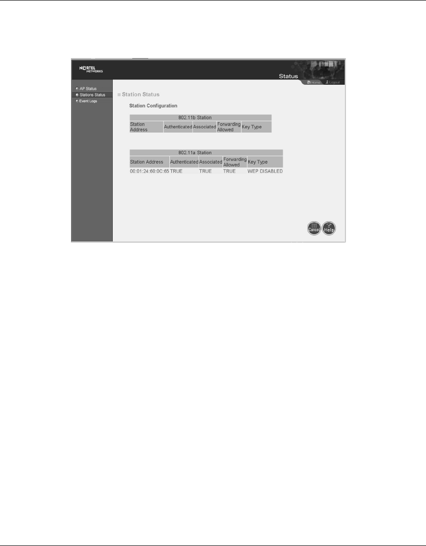
Station Status
Figure 26 Station Status screen
Click “Station Status” to view connected station configuration (Figure 26). The
“Station Statistics” page displays basic connection information for all associated
stations. The page is automatically refreshed every five seconds.

60 Chapter 3 System Configuration
214853-B

61
Using the Nortel Networks Wireless LAN Access Point 2220/2221
Appendix A
Specifications
This appendix provides technical specifications for the Access Point 2220/2221.
Available Channels
Available channels will vary according to current local regulations. For information on configuring the Nortel
Networks Wireless LAN Access Point 2220/2221 for the country you are in, go to http://support.nortelnetworks.com/
, select “Wireless LAN” and then “WLAN Access Point 2220” or “WLAN Access Point 2221”.
Maximum Clients
Settable range using the CLI is 0 to 2007; the default setting is 64.
Data Rate
Normal Mode: 6, 9, 12, 18, 24, 36, 48, 54 Mbps per channel
Turbo Mode: 12, 18, 24, 36, 48, 72, 96, 108 Mbps per channel
Operating Frequency
5.15 - 5.25 GHz (lower band) US/Canada, Japan
5.25 - 5.35 GHz (middle band) US/Canada
5.725 - 5.825 GHz (upper band) US/Canada
Channel selection will vary according to current local regulations.

62 Appendix A Specifications
214853-B
Power supply
Input: 100-240 VAC, 50-60 Hz;
Output: 5 VDC, 3 A
Power over Ethernet (POE) circuitry: Input voltage 48 VDC, 12.95W maximum
Output Power
Maximum power setting will vary according to current local regulations.
Physical Size
20.5 x 13.6 x 4 cm, (8.07 x 5.35 x 1.58 in)
Weight
700 grams (1.5 lbs.)
LED Indicators
Ready (Power), LAN (Ethernet Link/Activity), WLANa and WLANb (Wireless Link/Activity)
Management
HTML Web-browser interface
Command line interface (connection via the console port requires a serial terminal-emulation program and a
nullmodem cable and connector to match the female DB-9 connector on the Access Point 2220/2221 console port.)
Temperature
Operating: 0 to 55 ºC (32 to 122 ºF)
Storage: 0 to 70 ºC (32 to 158 ºF)

Appendix A Specifications 63
Using the Nortel Networks Wireless LAN Access Point 2220/2221
Humidity
5% to 95% (non-condensing)
Compliance Standards
Safety:
UL 60950
CAN/CSA-22.2 No. 60950
IEC 60950/EN60950, CB certificate and report with all national deviations
Radio Approvals:
FCC Part 15.247 (2.4 GHz)
FCC Part 15.401-15.407 (5 GHz)
RSS-139-1, RSS-210 (Canada)
EN 300.329 (Europe, 2.4 GHz)
EN 301.893 (Europe, 5 GHz)
EMI and Susceptibility (Class B):
FCC Part 15.107 and 15.109
ICES-003 (Canada)
EN 301.489-1 and -17 (Europe)
Other:
IEEE 802.11a and 802.11b
FCC Bulletin OET-65C (Human exposure to RF Fields)
RSS-102 (Canada)
Standards
IEEE 802.3 10BASE-T, IEEE 802.3u 100BASE-TX, IEEE 802.11a/b
Support for Power over Ethernet, IEEE 802.3af Draft V3
Warranty
Limited Lifetime

64 Appendix A Specifications
214853-B
65
Using the Nortel Networks Wireless LAN Access Point 2220/2221
Appendix B
Template for placing the Access Point 2220/2221
The template on the next page can be used to assist in positioning the Access Point
2220/2221. Mark where the wall-mount screws should go. For proper ventilation,
allow at least 1 inch (2.54 centimeters) clearance around the ventilation holes on
your Access Point 2220/2221.
Note: Because of variations that exist from printer to printer, please
verify that the template matches the mounting holes on the Access Point
2220/2221.

67
Using the Nortel Networks Wireless LAN Access Point 2220/2221
Appendix C
Mounting the Access Point 2220/2221 on a Drop
Ceiling
You can mount the Nortel Networks Wireless LAN Access Point 2220/2221 on a
drop ceiling (sometimes referred to as an acoustic or suspended ceiling) using the
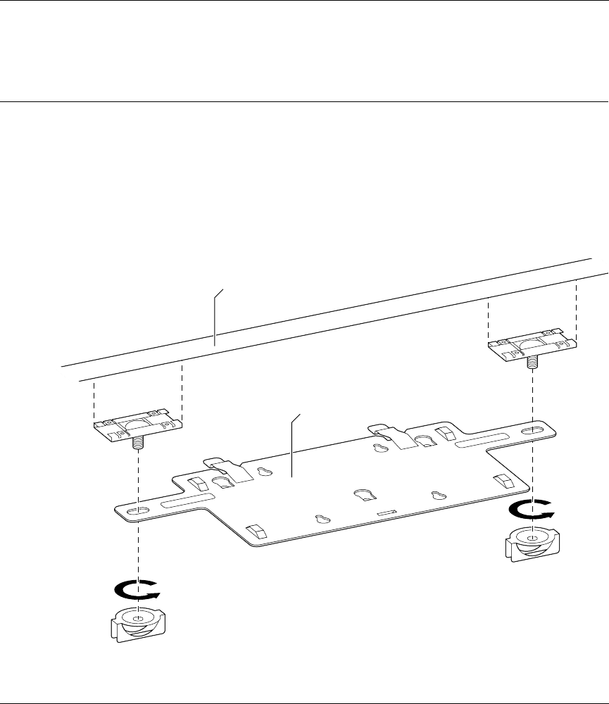
optional mounting bracket (Figure 28). The bracket attaches to a drop ceiling
T-rail and provides a mounting surface for the Access Point 2220/2221.
Figure 28 Optional mounting bracket
10983EA
Washer nut
Washer nut
Mounting
bracket
Drop ceiling
T-rail
Clamp
Clamp

68 Appendix C Mounting the Access Point 2220/2221 on a Drop Ceiling
214853-B
Attaching the mounting bracket to a drop ceiling
To attach the mounting bracket to a drop ceiling:
1Loosen the two washer nuts to allow the T-rail clamps to slide freely. Do not
remove the washer nuts.
2Place the mounting bracket in the desired location and position the T-rail
clamps around the drop ceiling T-rail.
3Holding the T-rail clamps in place around the T-rail, tighten both washer nuts
securely.
Verify that the mounting bracket is now securely attached to the drop ceiling
T-rail.
4Attach the Access Point 2220 to the mounting bracket.
Attaching the Access Point 2220/2221 to the mounting
bracket
To attach the Access Point 2220/2221 to the mounting bracket:
1Align the slotted mounting holes on the Access Point 2220/2221 with the
mounting tabs on the bracket.
2Press the Access Point 2220/2221 against the bracket, inserting the mounting
tabs into the slotted mounting holes.
3Slide the Access Point 2220/2221 so that the mounting tabs move into the
narrow part of the slotted mounting holes. The spring clips will lock the
Access Point 2220/2221 in place when it is properly positioned.
4Refer to See Chapter 1, “Hardware Installation,” on page 19 for instructions
on positioning the antennae and connecting the Ethernet cable and power
supply cable (if required) to the access point.