Accton Wireless Broand FIU176205000W Draft 11n Wireless Broadband Router User Manual UserMan V8YFIU176205000W
Accton Wireless Broadband Corp. Draft 11n Wireless Broadband Router UserMan V8YFIU176205000W
UserManual.wiki
>
Accton Wireless Broand
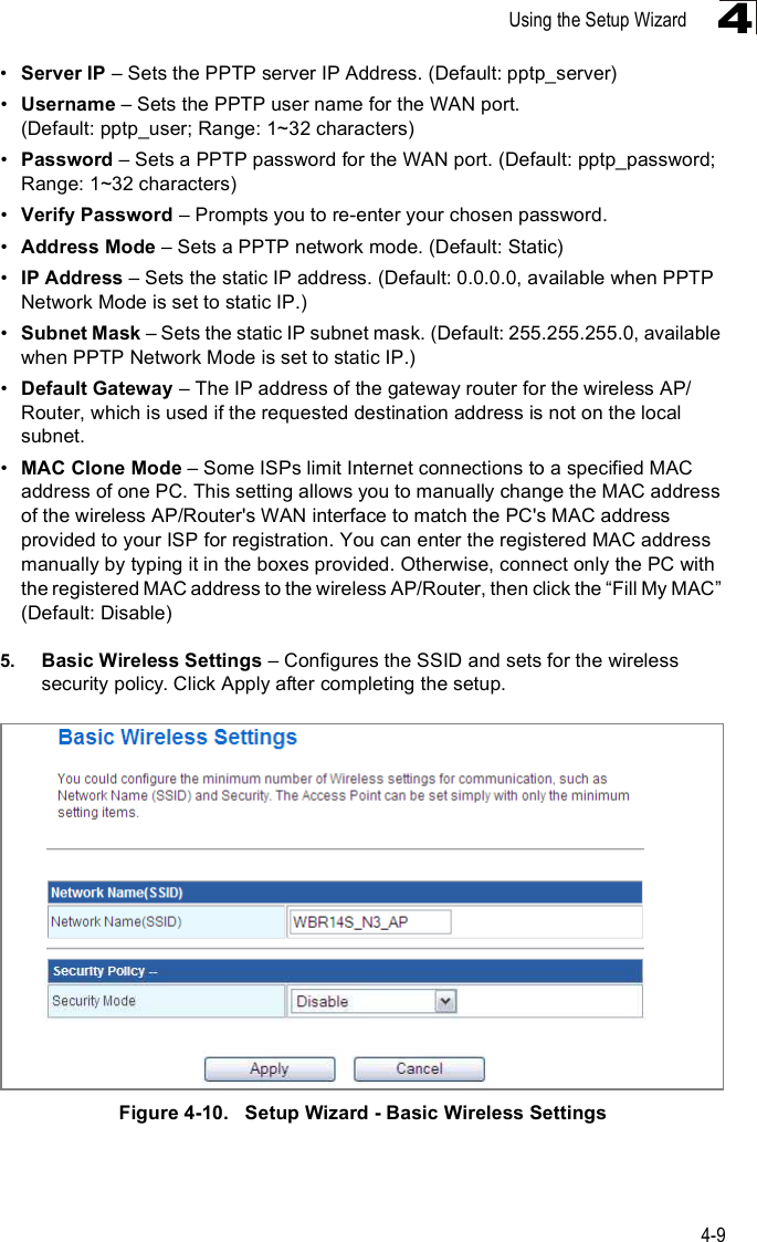
>
FIU176205000W User Manual
>
Manual
Contents
1.
Manual
2.
User Manual
Manual
Navigation menu
Upload a User Manual
Namespaces
Wiki Guide
HTML
PDF
Info
Views
User Manual
Discussion / Help
Navigation


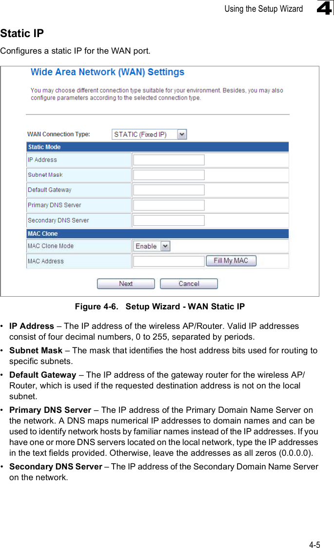
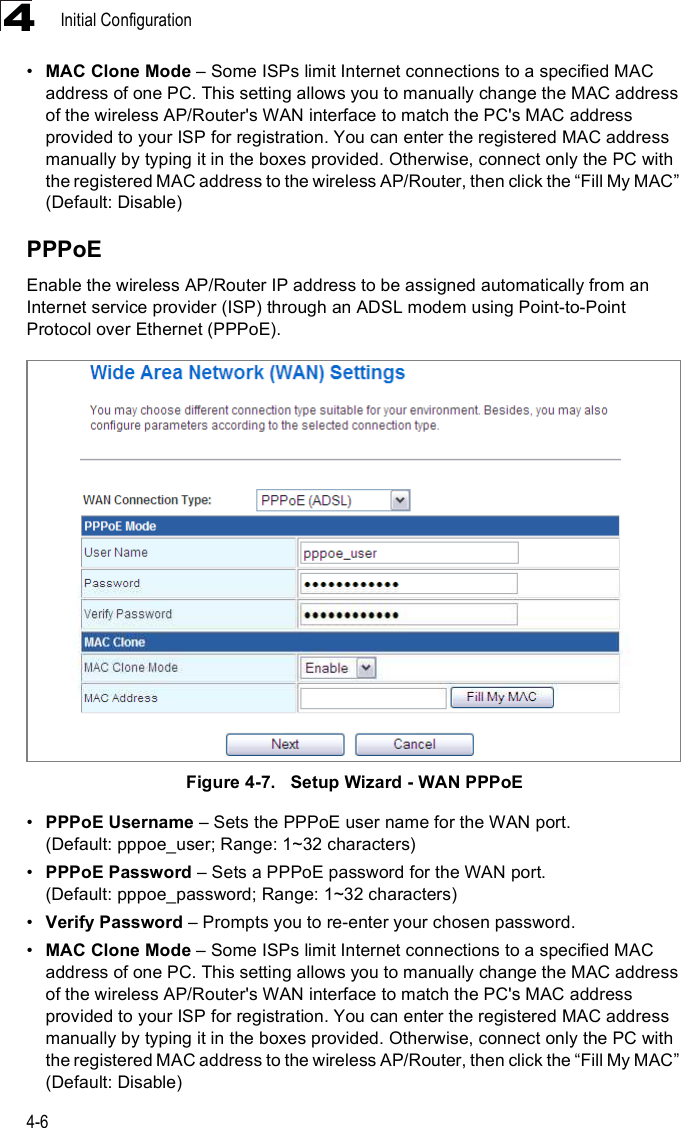
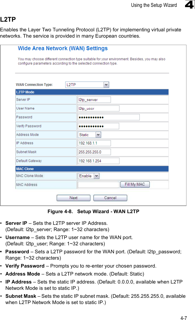
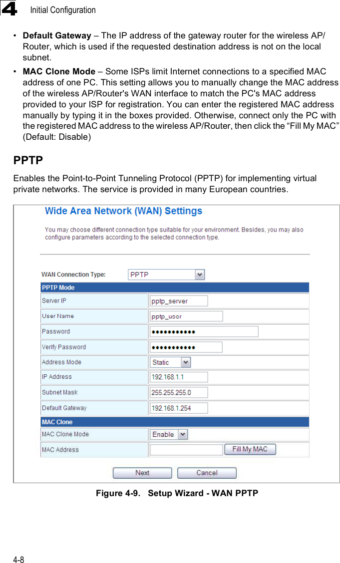

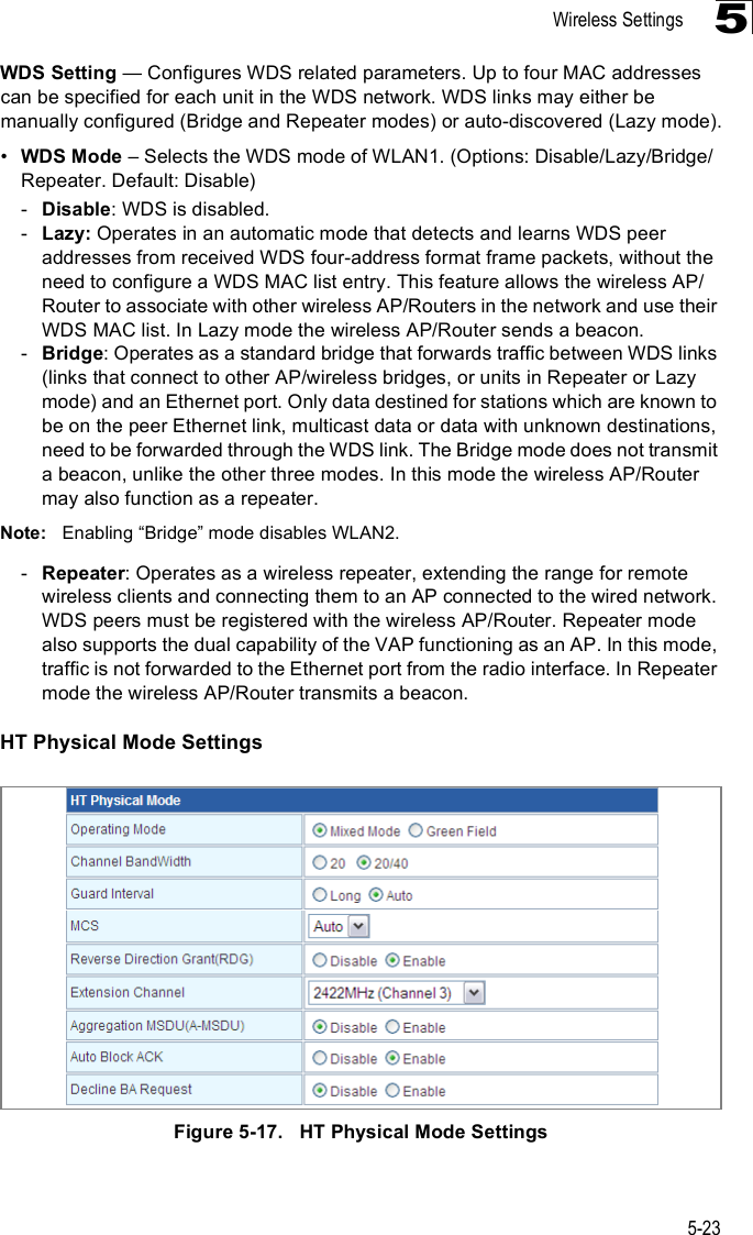
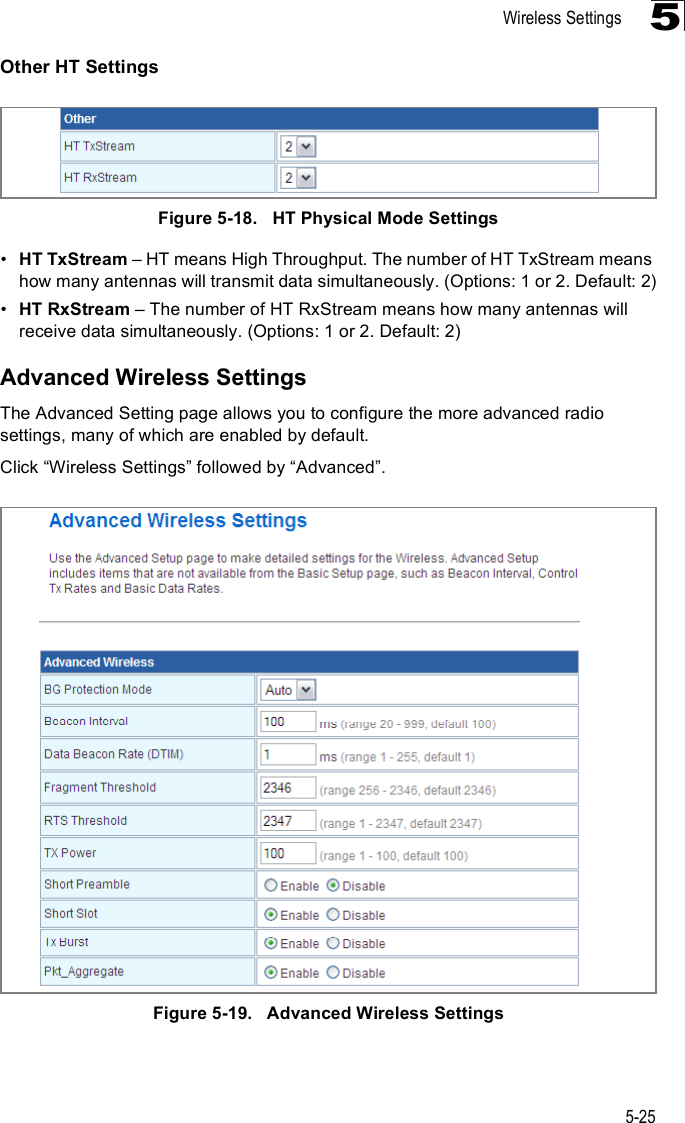
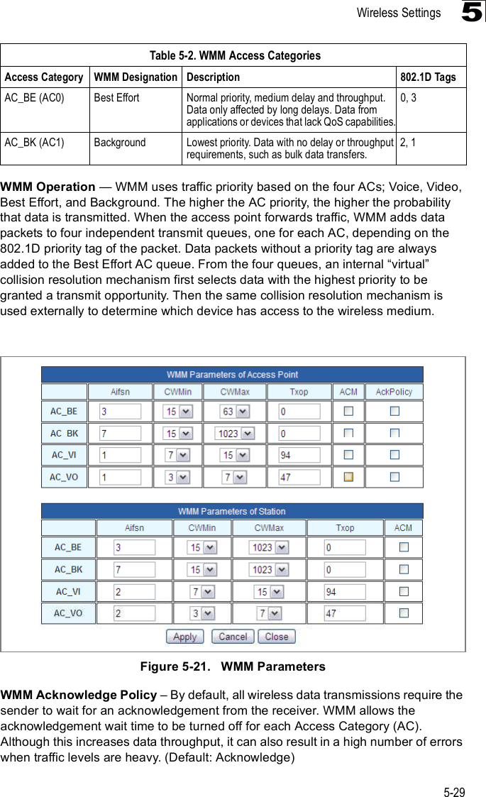
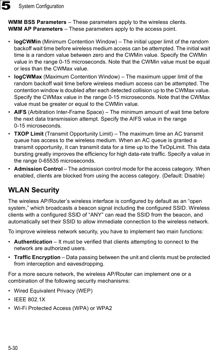
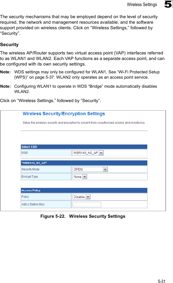
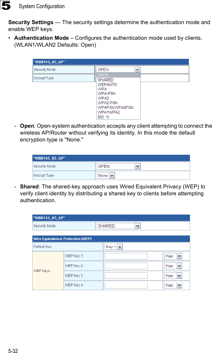
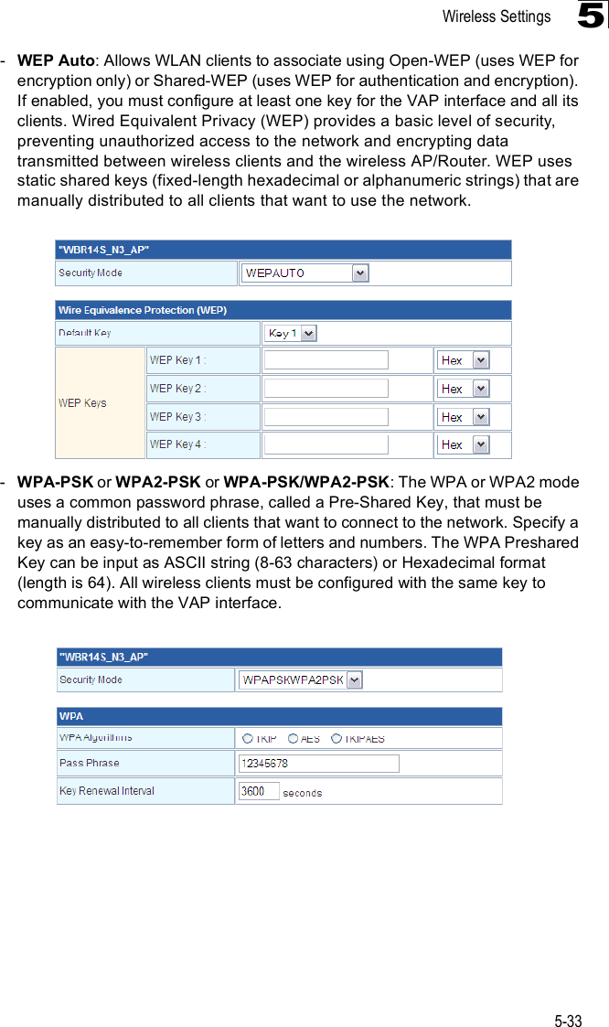
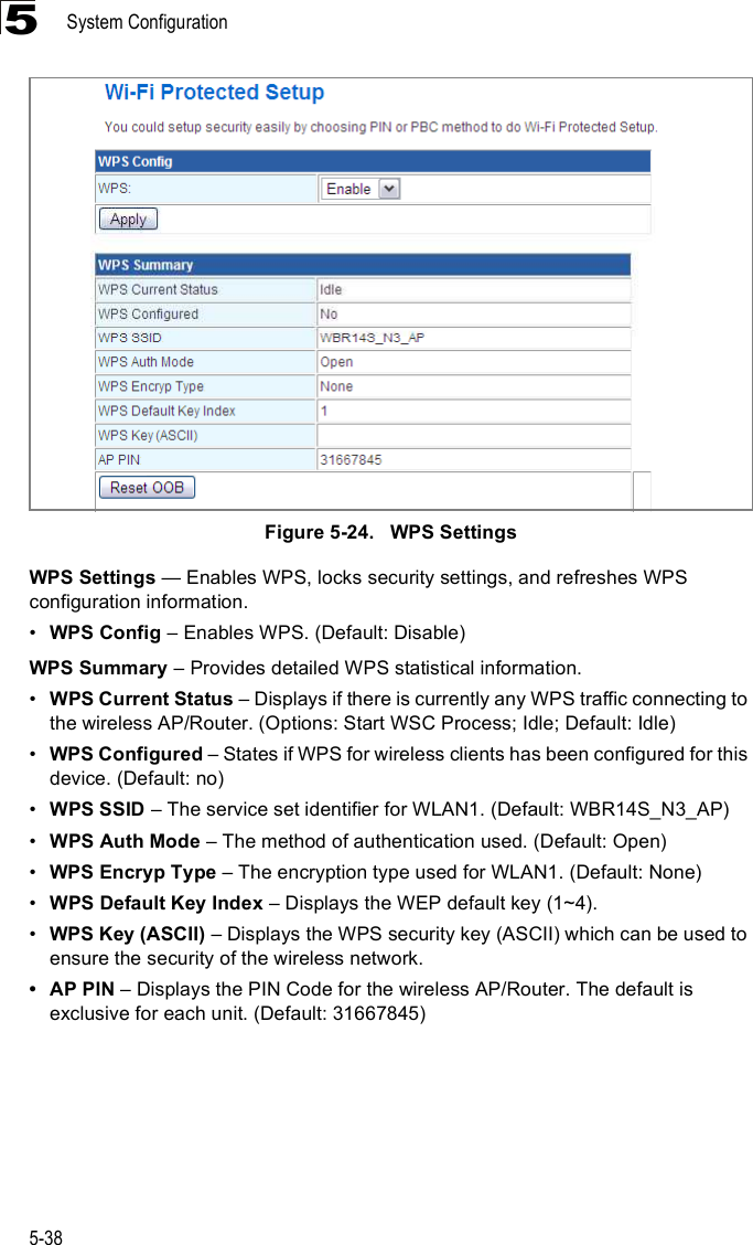
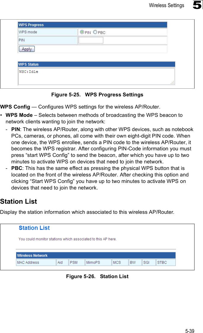
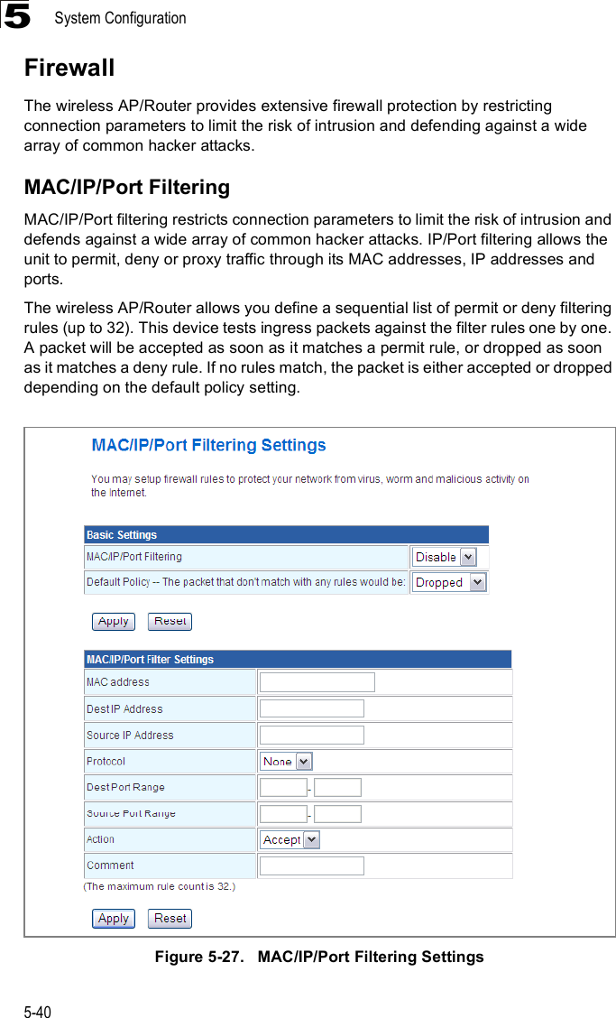
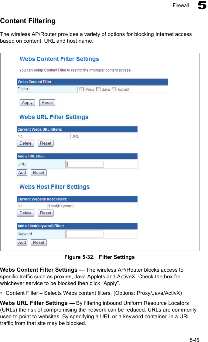
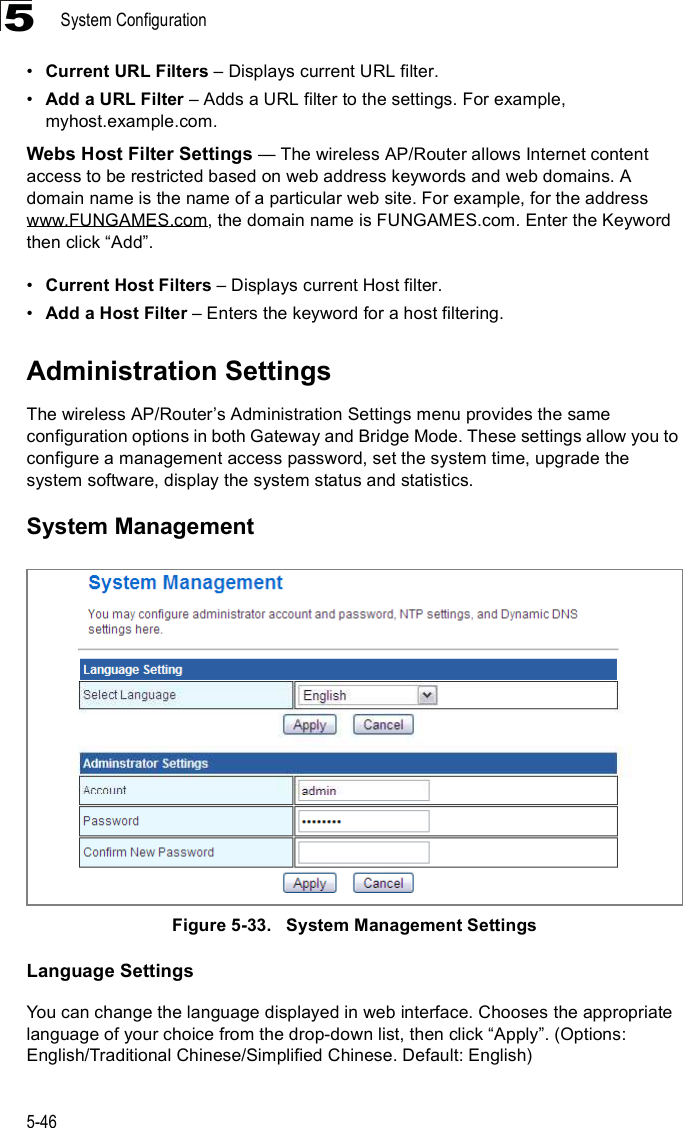
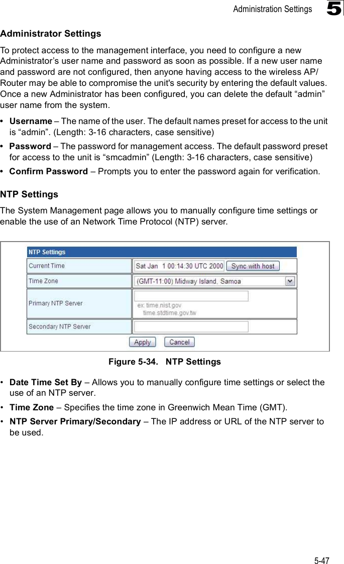
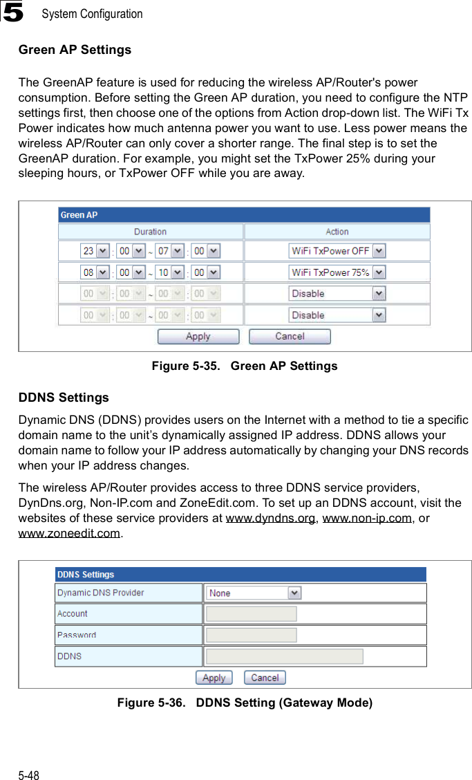
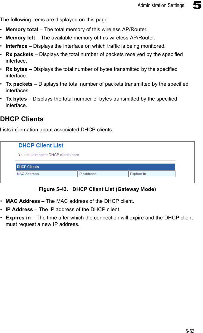
![System Configuration5-245!HT Operation Mode & Packets from 802.11n clients are referred to as High Throughput (HT) Greenfield packets, in other words packets that can be transmitted at rates of up to 300 Mbps assuming that HT Channel Bandwidth is set to 20/40Mhz, see HT Channel Bandwidth next page. Note: Some 802.11n wireless clients may be capable of transmission rates of up to 600 Mbps, however the wireless AP/Router will only be able to connect to them at a maximum transmission rate of 300 Mbps.802.11b/g packets are referred to as non-HT packets, being transmitted at lower throughput rates. HT mixed format frames contain a preamble compatible with the non-HT receivers. HT Greenfield frames do not contain a non-HT compatible part. Support for HT Greenfield format is optional. An HT station that does not support the reception of an HT Greenfield format frame must be able to detect that an HT Greenfield format frame is an HT transmission (as opposed to a non-HT transmission). In this case the receiver must decode the high throughput signal (HT-SIG) in the packet header and determine if the HT-SIG cyclic redundancy check (CRC) passes. (Default: Mixed)!HT Channel Bandwidth & The wireless AP/Router provides a channel bandwidth of 40 MHz by default giving an 802.11g connection speed of 108 Mbps (sometimes referred to as Turbo Mode) and a 802.11n connection speed of up to 300 Mbps. Setting the HT Channel Bandwidth to 20 MHz slows connection speed for 802.11g and 802.11n to 54 Mbps and 74 Mbps respectively and ensures backward compliance for slower 802.11b devices. (Default: 20/40MHz)!Guard Interval & The guard interval between symbols helps receivers overcome the effects of multipath delays. When you add a guard time, the back portion of useful signal time is copied and appended to the front. (Default: Auto)!MCS & The Modulation and Coding Scheme (MCS) is a value that determines the modulation, coding and number of spatial channels. (Options: value [range] = 0~7 (1 Tx Stream), 8~15 (2 TxStream), 32 and auto (33). Default: auto)!Reverse Direction Grant (RDG) & When enables Reverse Direction Grant, the wireless AP/Router can reduce the transmitted data packet collision by using the reverse direction protocol. During TXOP (Transmission Opportunity) period, the receiver could use remaining transmission time to transmit data to a sender. The RDG improves transmission performance and scalability in a wireless environment. !Extension Channel & When 20/40MHz channel bandwidth has been set, the extension channel option will be enabled. The extension channel will allow you to get extra bandwidth. (Options: 2417MHz/Channel 2, 2457MHz/Channel 10. Default: 2457MHz/Channel 10.)!Aggregate MSDU (A-MSDU) & This option enables Mac Service Data Unit (MSDU) aggregation. (Default: Disable)!Auto Block ACK & Select to block ACK (Acknowledge Number) or not during data transferring.!Decline BA Request & Select to reject peer BA-Request or not.](https://usermanual.wiki/Accton-Wireless-Broand/FIU176205000W.Manual/User-Guide-1141517-Page-60.png)