Accton Wireless Broand FIU816202T00W 150Mbps Wireless-N Mini 3G Broadband Router User Manual User Guide
Accton Wireless Broadband Corp. 150Mbps Wireless-N Mini 3G Broadband Router User Guide
UserManual.wiki
>
Accton Wireless Broand
>
FIU816202T00W User Manual
>
UserMan-BG-100-Rev
Contents
1.
User Manual SMCWBR11S-N
2.
User Manual WR6202
3.
UserMan-BG-100-Rev
4.
UserMan-SMCWBR11S-3GN-Rev
5.
UserMan-WBR6202-1U-Rev
UserMan-BG-100-Rev
Navigation menu
Upload a User Manual
Namespaces
Wiki Guide
HTML
PDF
Info
Views
User Manual
Discussion / Help
Navigation
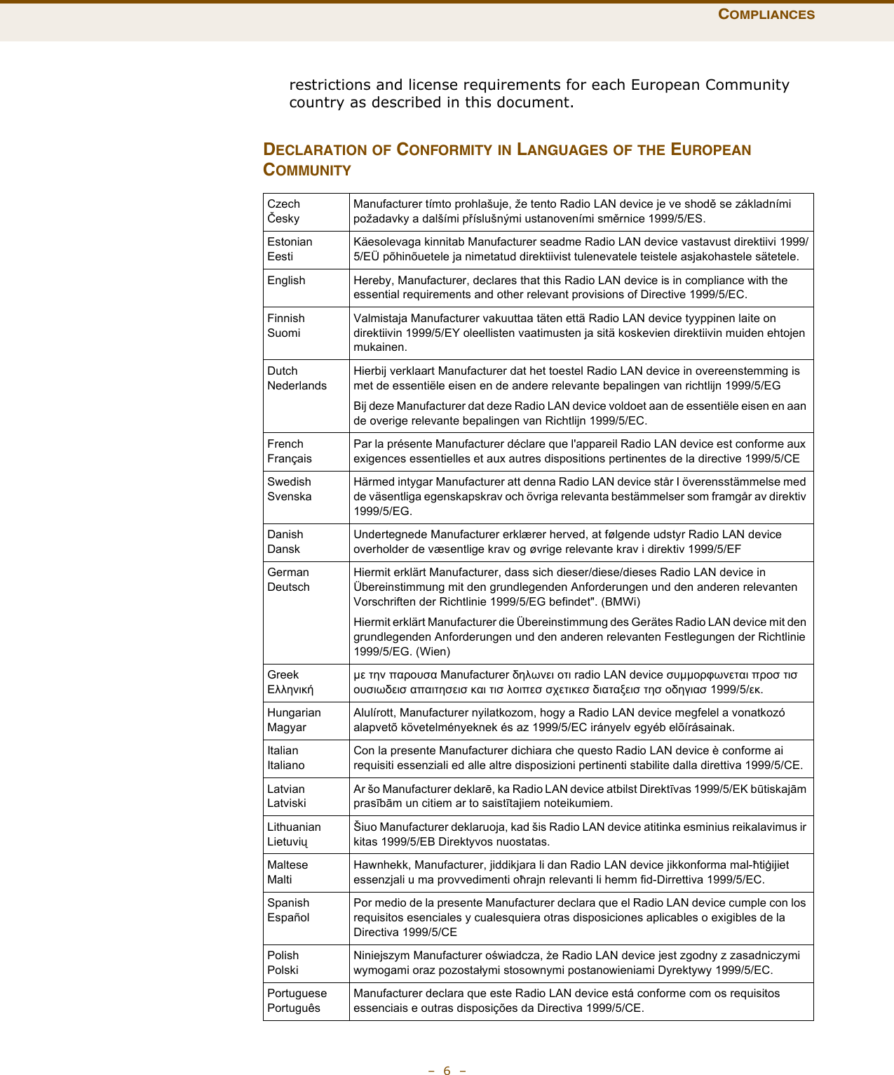

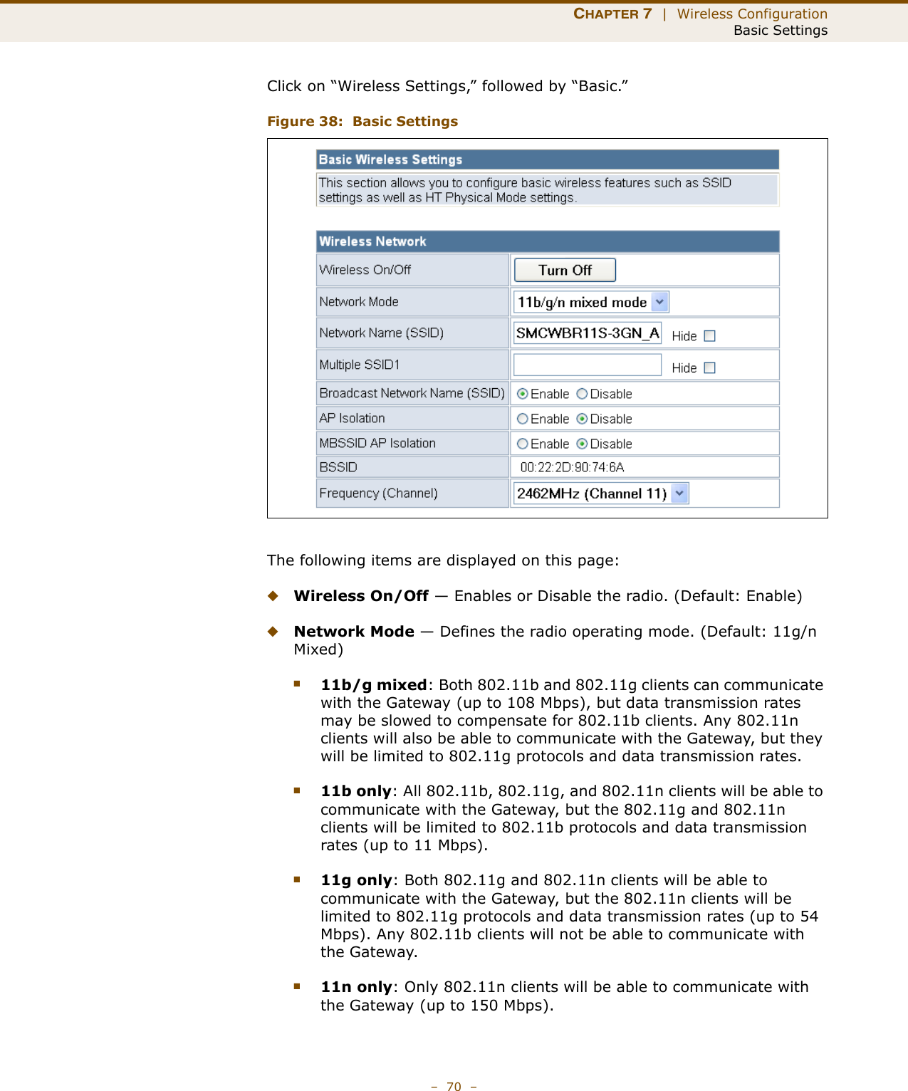
![CHAPTER 7 | Wireless ConfigurationBasic Settings– 72 –HT PHYSICAL MODESETTINGSThe HT Physical Mode section on the Wireless Settings Advanced page includes additional parameters for 802.11n operation.Figure 39: HT Physical Mode SettingsThe following items are displayed in this section on this page:◆HT Channel Bandwidth — The Gateway provides a channel bandwidth of 40 MHz by default giving an 802.11g connection speed of 108 Mbps (sometimes referred to as Turbo Mode) and a 802.11n connection speed of up to 150 Mbps. Setting the HT Channel Bandwidth to 20 MHz slows connection speed for 802.11g and 802.11n to 54 Mbps and 74 Mbps respectively and ensures backward compliance for slower 802.11b devices. (Default: 20MHz)◆Guard Interval — The guard interval between symbols helps receivers overcome the effects of multipath delays. When you add a guard time, the back portion of useful signal time is copied and appended to the front. (Default: Auto)◆MCS — The Modulation and Coding Scheme (MCS) is a value that determines the modulation, coding and number of spatial channels. (Options: value [range] = 0~7 (1 Tx Stream), 8~15 (2 TxStream), 32 and auto (33). Default: auto)◆Reverse Direction Grant (RDG) — When Reverse Direction Grant is enabled, the Gateway can reduce the transmitted data packet collision by using the reverse direction protocol. During TXOP (Transmission Opportunity) period, the receiver could use remaining transmission time to transmit data to a sender. The RDG improves transmission performance and scalability in a wireless environment. ◆Extension Channel — When 20/40MHz channel bandwidth has been set, the extension channel option will be enabled. The extension channel will allow you to get extra bandwidth. (Options: 2417MHz/Channel 2, 2457MHz/Channel 10. Default: AutoSelect.)](https://usermanual.wiki/Accton-Wireless-Broand/FIU816202T00W.UserMan-BG-100-Rev/User-Guide-1248094-Page-73.png)