Accton Wireless Broand FW181RG25011W WiMAX 802.16e Indoor Gateway User Manual User Guide
Accton Wireless Broadband Corp. WiMAX 802.16e Indoor Gateway User Guide
User manual rev

U
SER
G
UIDE
WiMAX 802.16e Indoor Gateway
RG231

U
SER
G
UIDE
RG231
Indoor IEEE 802.16e-2005 Mobile WiMAX Gateway,
with 2.3/2.5/3.5 GHz Frequency Band Support,
Four LAN (RJ-45) Ports,
Two VoIP (RJ-11) Ports,
and 802.11n Wi-Fi
RG231
E022010-CS-R01
XXXXXXXXXXXXX

– 3 –
COMPLIANCES
FEDERAL COMMUNICATION COMMISSION INTERFERENCE STATEMENT
This equipment has been tested and found to comply with the limits for a
Class B digital device, pursuant to Part 15 of the FCC Rules. These limits
are designed to provide reasonable protection against harmful interference
in a residential installation. This equipment generates, uses and can
radiate radio frequency energy and, if not installed and used in accordance
with the instructions, may cause harmful interference to radio
communications. However, there is no guarantee that interference will not
occur in a particular installation. If this equipment does cause harmful
interference to radio or television reception, which can be determined by
turning the equipment off and on, the user is encouraged to try to correct
the interference by one of the following measures:
◆Reorient or relocate the receiving antenna
◆Increase the separation between the equipment and receiver
◆Connect the equipment into an outlet on a circuit different from that to
which the receiver is connected
◆Consult the dealer or an experienced radio/TV technician for help
This device complies with Part 15 of the FCC Rules. Operation is subject to
the following two conditions: (1) This device may not cause harmful
interference, and (2) this device must accept any interference received,
including interference that may cause undesired operation.
FCC Caution: Any changes or modifications not expressly approved by the
party responsible for compliance could void the user's authority to operate
this equipment.
IMPORTANT NOTE:
FCC RADIATION EXPOSURE STATEMENT
This equipment complies with FCC radiation exposure limits set forth for an
uncontrolled environment. This equipment should be installed and
operated with minimum distance 20 cm between the radiator and your
body.
This transmitter must not be co-located or operating in conjunction with
any other antenna or transmitter.
Due to the essential high output power nature of WiMAX devices, use of
this device with other transmitters at the same time may exceed the FCC
RF exposure limit and such usage must be prohibited (unless such co-
transmission has been approved by FCC in the future).
C
OMPLIANCES
– 4 –
EC CONFORMANCE DECLARATION
Marking by the above symbol indicates compliance with the Essential
Requirements of the R&TTE Directive of the European Union (1999/5/EC).
This equipment meets the following conformance standards:
◆EN 60950-1 (IEC 60950-1) - Product Safety
◆EN 301 489-1, EN 301 489-4, EN 302 326-2 (V1.2.2), EN 302 326-3
(V1.2.2) - EMC requirements for radio equipment
This device is intended for use in all European Community countries.
NCC 警語
Wi-Fi:
經型式認證合格之低功率射頻電機 , 非經許可 , 公司、商號或使用者均不得擅
自變更頻率、加大功率或變更原設計之特性及功能。
低功率射頻電機之使用不得影響飛航安全及干擾合法通信 ; 經發現有干擾現象
時 , 應立即停用 , 並改善至無干擾時方得繼續使用。前項合法通信 , 指依電信
法規定作業之無線電通信。低功率射頻電機須忍受合法通信或工業、科學及醫
療用電波輻射性電機設備之干擾。
「本產品內含射頻模組 : CCAI09LP1650T1」
WiMAX:
減少電磁波影響 , 請妥適使用。
0560
– 5 –
ABOUT THIS GUIDE
PURPOSE This guide details the hardware features of the RG231 WiMAX CPE,
including its physical and performance-related characteristics, and how to
install the device and use its configuration software.
AUDIENCE This guide is for PC users with a working knowledge of computers. You
should be familiar with Windows operating system concepts.
CONVENTIONS The following conventions are used throughout this guide to show
information:
N
OTE
:
Emphasizes important information or calls your attention to related
features or instructions.
C
AUTION
:
Alerts you to a potential hazard that could cause loss of data, or
damage the system or equipment.
W
ARNING
:
Alerts you to a potential hazard that could cause personal injury.
RELATED PUBLICATIONS The following publication gives basic information on how to install and use
the WiMAX CPE.
Quick Installation Guide
Also, as part of the CPE’s configuration software, there is online help that
describes all management features.
REVISION HISTORY This section summarizes the changes in each revision of this guide.
FEBRUARY 2010 REVISION
This is the first revision of this guide. This guide is valid for software
version 0.0.2.10.

– 6 –
CONTENTS
COMPLIANCES 3
ABOUT THIS GUIDE 5
CONTENTS 6
FIGURES 9
TABLES 11
SECTION I GETTING STARTED 12
1INTRODUCTION 13
RG231 Hardware Description 14
Wi-Fi Option 14
WPS/Scan Button 14
Power Status LED 15
Wi-Fi Status LED 15
WPS Status LED 16
WiMAX Signal LEDs 16
10BASE-T/100BASE-TX LAN Ports 17
VoIP Phone Ports 17
USB Port 17
Power Adapter Socket 17
WPS/Scan Button 18
Reset Button 18
2INSTALLING THE RG231 19
Package Checklist 19
Installation Overview 19
Select a Location 19
Cable Connections 20
3INITIAL CONFIGURATION 22

C
ONTENTS
– 7 –
Accessing the Web Management Interface 22
Home Page 23
Using the Basic Setup Wizard 24
The Advanced Setup Menu 26
SECTION II WEB CONFIGURATION 27
4SYSTEM SETTINGS 28
System Status 29
Administrator Settings 30
Firmware Upgrade 31
Configuration Tools 31
System Time 32
Reset 33
5GATEWAY CONFIGURATION 34
WAN Settings 35
Dynamic IP Address 35
Static IP Settings 36
L2TP Settings 36
DNS 37
NAT 37
Port Mapping 37
DMZ 39
Route 40
SECTION III APPENDICES 41
ATROUBLESHOOTING 42
Diagnosing LED Indicators 42
Cannot Connect to the Internet 42
Cannot Access Web Management 43
Forgot or Lost the Password 43
Resetting the Unit 43
BHARDWARE SPECIFICATIONS 44
Physical Specifications 44


– 9 –
FIGURES
Figure 1: Front of the RG231 14
Figure 2: RG231 LED Indicators 15
Figure 3: Back of the RG231 16
Figure 4: Top of the RG231 18
Figure 5: Base of the RG231 18
Figure 6: RG231 Connections 20
Figure 7: Login Page 22
Figure 8: Home Page 23
Figure 9: WiMAX Account Login 24
Figure 10: Confirm Settings 25
Figure 11: Setup Wizard Finished 25
Figure 12: Advanced Setup 26
Figure 13: System Status – Internet 29
Figure 14: System Status – Gateway 29
Figure 15: System Status – Information 30
Figure 16: Setting a Password 30
Figure 17: Firmware Upgrade 31
Figure 18: Configuration Tools 31
Figure 19: Restore Configuration Settings 32
Figure 20: System Time 32
Figure 21: Reset Unit 33
Figure 22: WAN Settings 35
Figure 23: Dynamic IP Address 35
Figure 24: Static IP Settings 36
Figure 25: L2TP Settings 36
Figure 26: DNS Settings 37
Figure 27: Port Mapping 38
Figure 28: DMZ Settings 39
Figure 29: Routing Table 40
Figure 30: RJ-45 Connector 48
Figure 31: Straight Through Wiring 49


– 11 –
TABLES
Table 1: RG231 Models 13
Table 2: Power Status LED 15
Table 3: Wi-Fi Status LED 15
Table 4: WPS Status LED 16
Table 5: WiMAX Signal Status LEDs 16
Table 6: LAN Port Status LEDs 17
Table 7: System Settings 28
Table 8: Gateway Configuration 34
Table 9: Troubleshooting Chart 42
Table 10: 10/100BASE-TX MDI and MDI-X Port Pinouts 49
Table 11: RJ-11 Port Pinout 51

– 12 –
S
ECTION
I
GETTING STARTED
This section provides an overview of the RG231, and describes how to
install and mount the unit. It also describes the basic settings required to
access the management interface and run the setup Wizard.
This section includes these chapters:
◆“Introduction” on page 13
◆“Installing the RG231” on page 19
◆“Initial Configuration” on page 22

– 13 –
1INTRODUCTION
The RG231 WiMAX 802.16e Self-Install Residential Gateway is a WiMAX
subscriber station designed to provide Internet access for a home or small
office. The unit provides a gateway function between a WiMAX service
provider and a local Ethernet LAN. The device enables a service provider to
deliver last mile broadband wireless access as an alternative to wired DSL
or cable modems.
The RG231 is a plug-and-play device. There are several available models
for each of the 2.3, 2.5, and 3.5 GHz WiMAX frequency bands. Which
model you use will depend on the frequency band of your service provider’s
WiMAX service.
The RG231 includes four RJ-45 Ethernet switch ports for LAN connections
and two RJ-11 Voice over IP (VoIP) phone ports. Units also support an
IEEE 802.11b/g/n Wi-Fi module that provides a local Wi-Fi access point
service.
The RG231 offers a user-friendly web-based management interface for the
configuration of all the unit’s features. Any PC directly attached to the unit
can access the management interface using a web browser, such as
Internet Explorer (version 6.0 or above) or Firefox (version 1.5 or above).
C
HAPTER
1
| Introduction
RG231 Hardware Description
– 14 –
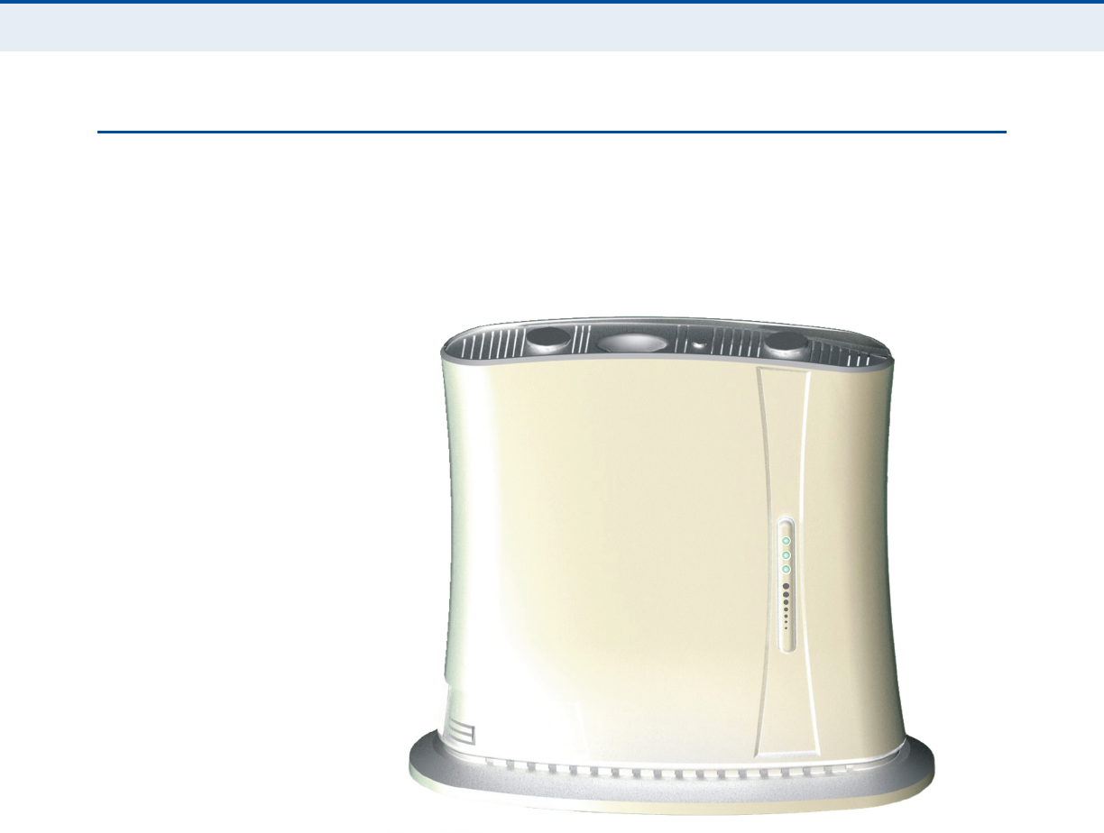
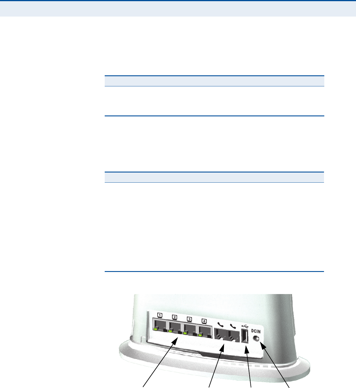
RG231 HARDWARE DESCRIPTION
The front of the RG231 provides an array of system status indicators. The
back includes four LAN ports for 10/100 Mbps Ethernet connections, two
RJ-11 VoIP phone ports (on some models), and a DC power jack.
Figure 1: Front of the RG231
WI-FI OPTION The RG231 includes an 802.11b/g/n Wi-Fi support. This unit includes
internal antennas for local wireless connections to PCs.
WPS/SCAN BUTTON Press to automatically authenticate Wi-Fi Protected Setup (WPS) devices in
the Wi-Fi network. Press and hold down for more than 5 seconds to
perform a scan of WiMAX frequencies.
C
HAPTER
1
| Introduction
RG231 Hardware Description
– 15 –
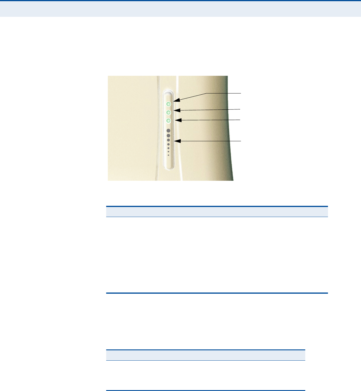
POWER STATUS LED The RG231 includes a Power LED indicator that simplifies installation and
WiMAX network troubleshooting. The LED, which is located on the front
panel, is described in the following table.
Figure 2: RG231 LED Indicators
WI-FI STATUS LED The models that support Wi-Fi operation include a Wi-Fi LED indicator that
displays the Wi-FI network status. The LED, which is located on the front
panel, is described in the following table.
Table 1: Power Status LED
Status Description
On Green The unit has completed entry to a WiMAX network.
On Amber Indicates one of the following conditions:
◆After power on, indicates the unit is running its self test.
◆Indicates that the network entry process is in progress or has
restarted.
Blinking Amber When blinking with three of the WiMAX signal LEDs turned on, indicates
authentication has failed.
On Red A system failure has occured.
Off No power is being supplied to the unit.
Power Status LED
Wi-Fi Status LED
WiMAX Signal LEDs
WPS Status LED
Table 2: Wi-Fi Status LED
Status Description
On Green The Wi-Fi radio is enabled and operating normally.
Flashing Green Indicates data traffic in the Wi-Fi network.
Off There is no Wi-Fi connection or the radio is disabled.
C
HAPTER
1
| Introduction
RG231 Hardware Description
– 16 –
WPS STATUS LED The models that support Wi-Fi operation include a WPS LED indicator that
displays the status of the Wi-Fi Protected Setup. The LED, which is located
on the front panel, is described in the following table.
WIMAX SIGNAL LEDSThe RG231 includes seven WiMAX signal strength LED indicators that
display the current WiMAX receive signal status. The LEDs, which are
located on the front panel, are described in the following table.
Figure 3: Back of the RG231
Table 3: WPS Status LED
Status Description
On Green WPS authentication of a client has been sucessfully completed.
Flashing Green WPS authentication of a client is in progress.
Off There is no WPS authentication in progress.
Table 4: WiMAX Signal Status LEDs
LED Status Description
1 On Blue Indicates the receive signal is 5 dB or more.
2 On Blue Indicates the receive signal is 8 dB or more.
3 On Blue Indicates the receive signal is 12 dB or more.
4 On Blue Indicates the receive signal is 15 dB or more.
5 On Blue Indicates the receive signal is 18 dB or more.
6 On Blue Indicates the receive signal is 20 dB or more.
7 On Blue Indicates the receive signal is 25 dB or more.
1-7 in sequence On Blue The unit is scanning frequency channels.
All 7 LEDs Off No power is being supplied to the unit.
RJ-45 LAN Ports
(include Link/Activity LEDs)
VoIP Phone Ports Power SocketUSB Port

C
HAPTER
1
| Introduction
RG231 Hardware Description
– 17 –
10BASE-T/
100BASE-TX LAN
PORTS
The RG231 provides four 10BASE-T/100BASE-TX RJ-45 ports. These LAN
ports are standard RJ-45 Ethernet network ports that connect directly to
PCs. They can also be connected to an Ethernet switch or hub to support
more users.
All ports support automatic MDI/MDI-X operation, so you can use straight-
through cables for all network connections to PCs or servers, or to other
switches or hubs. Each of these ports support auto-negotiation, so the
optimum transmission mode (half or full duplex), and data rate (10 or
100 Mbps) is selected automatically.
Each RJ-45 port includes a built-in LED indicator. This LED indicator is
described in the following table.
VOIP PHONE PORTS Some RG231 models optionally provide two RJ-11 telephone ports that
connect directly to a standard (analog) telephone set. This allows a regular
telephone to be used for making VoIP calls over the Internet.
USB PORT Reserved for future use.
POWER ADAPTER
SOCKET
The power socket is located on the rear panel of the RG231. The power
socket is for the AC power adapter connection.
The unit is powered on when connected to its AC power adapter, and the
power adapter is connected to an AC power source between 100-240 volts
at 50-60Hz.
Table 5: LAN Port Status LEDs
LED Status Description
Link/Activity On Green Ethernet port has a valid link with an attached device.
Flashing Green The port is transmitting or receiving data.
Off Ethernet port has no link with another device.
C
HAPTER
1
| Introduction
RG231 Hardware Description
– 18 –
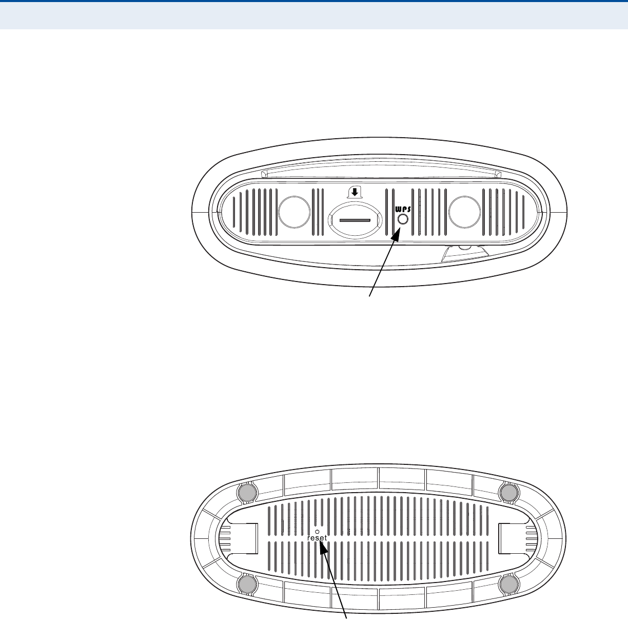
WPS/SCAN BUTTON Press to automatically authenticate Wi-Fi Protected Setup (WPS) devices in
the Wi-Fi network. Press and hold down for more than 5 seconds to
perform a scan of WiMAX frequencies.
Figure 4: Top of the RG231
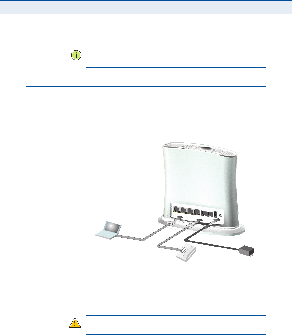
RESET BUTTON The Reset button is located on the base of the RG231 and is used to reset
the unit or restore the factory default configuration. If you press the button
for less than 1 second, the unit will perform a hardware reset. If you press
and hold down the button for 5 seconds or more, any configuration
changes you may have made are removed, and the factory default
configuration is restored to the unit.
Figure 5: Base of the RG231
WPS Button
Reset Button

– 19 –
2INSTALLING THE RG231
This section describes how to install and connect the RG231 WiMAX
802.16e Self-Install Residential Gateway.
PACKAGE CHECKLIST
The RG231 package includes:
◆RG231 unit (RG231-2.3, RG231-2.5, or RG231-3.5)
◆RJ-45 Category 5 network cable
◆AC power adapter
◆Quick Installation Guide
◆User Guide CD
INSTALLATION OVERVIEW
Before installing the RG231, verify that you have all the items listed in the
package checklist above. If any of the items are missing or damaged,
contact your local dealer. Also, be sure you have all the necessary tools and
cabling before installing the RG231.
SELECT A LOCATION
The RG231 can be installed indoors on any horizontal surface, such as a
desktop or shelf.
When selecting a suitable location for the device, consider these
guidelines:
◆Select a cool, dry place, which is out of direct sunlight.
◆The device should have adequate space (approximately two inches) on
all sides for proper air flow.
◆The device must be near an AC power outlet that provides 100 to
240 V, 50 to 60 Hz.
C
HAPTER
2
| Installing the RG231
Cable Connections
– 20 –
◆The device should be accessible for network cabling and allow the
status LED indicators to be clearly visible.
N
OTE
:
If the RG231 displays a weak WiMAX receive signal, try moving it to
another location.
CABLE CONNECTIONS
The RG231 is a plug-and-play device, so once it has been connected to
your PC and powered up, it is fully operable.
Functioning as a gateway, the unit routes traffic between a WiMAX service
provider’s base station and PCs or notebooks in the local network.
Figure 6: RG231 Connections
To connect the RG231, follow these steps:
1. Power on the RG231 by by first connecting the AC power adapter to the
unit’s power socket, and then connecting the adapter to an AC power
source.
C
AUTION
:
Use ONLY the power adapter supplied with the RG231. Otherwise,
the product may be damaged.
Notebook Computer
Regular Phone
AC Power Adapter

C
HAPTER
2
| Installing the RG231
Cable Connections
– 21 –
2. Observe the Indicator LEDs. When you power on the RG231, verify that
the Power LED turns on and that the other LED indicators start
functioning as described under “RG231 Hardware Description” on
page 14.
3. Connect Category 5 or better Ethernet cables from the RG231’s LAN
ports to the network ports of your PCs. Alternatively, you can connect
the LAN ports to an Ethernet switch or other devices. Make sure the
length of each cable does not exceed 100 meters (328 ft).
If your PCs are powered on, the RJ-45 LAN port LEDs on the RG231
should turn on to indicate valid links.
4. (Optional) Connect one or two standard (analog) telephone sets to the
RG231’s VoIP ports using standard telephone cable with RJ-11 plugs.
The RG231 enables VoIP calls to be made through the unit using a
standard (analog) telephone set connected to a VoIP port, or from PCs
or other network devices connected to the LAN ports. Standard Session
Initiation Protocol (SIP) technology is used to make VoIP calls. You
must access the web interface and configure settings for your SIP
service provider before being able to make VoIP calls.
5. Use your PC’s web browser to access the unit’s management interface
and run the Setup Wizard to make any configuration changes. For more
information, see Chapter 3, “Initial Configuration.”
– 22 –
3INITIAL CONFIGURATION
The RG231 initial configuration steps can be made through its web
management interface using the Setup Wizard. It is recommended to make
the initial changes by connecting a PC directly to one of the RG231’s LAN
ports.
ACCESSING THE WEB MANAGEMENT INTERFACE
The RG231 has a default IP address of 192.168.1.1 and a subnet mask of
255.255.255.0. If your PC is set to have an IP address assigned by DHCP
(Dynamic Host Configuration Protocol), you can connect immediately to the
web management interface. Otherwise, you must first check if your PC’s IP
address is set on the same subnet as the RG231 (that is, the PC’s IP
address starts 192.168.1.x).
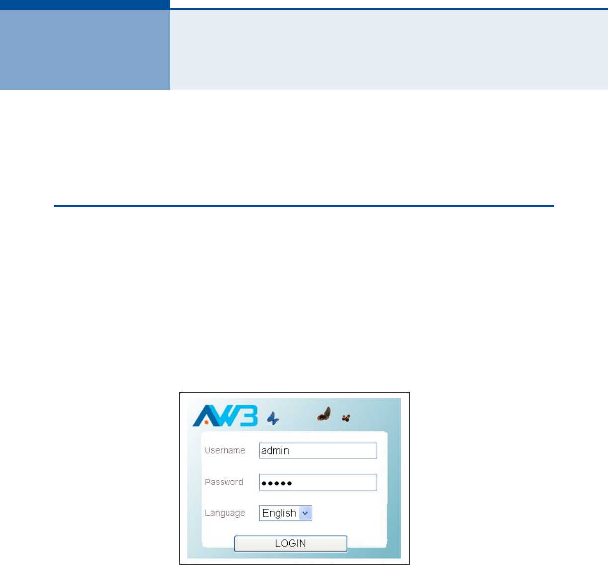
In the web browser’s address bar, type the default IP address: http://
192.168.1.1.
The web browser displays the RG231’s login page.
Figure 7: Login Page
Language – Selects English or Traditional Chinese as the web interface
language.
Logging In – Type the default User Name “admin” and Password “admin,”
then click Login. The home page displays.
C
HAPTER
3
| Initial Configuration
Accessing the Web Management Interface
– 23 –
N
OTE
:
It is recommended that you configure a user password as the first
step under “Administrator Settings” on page 4 to control management
access to the unit.
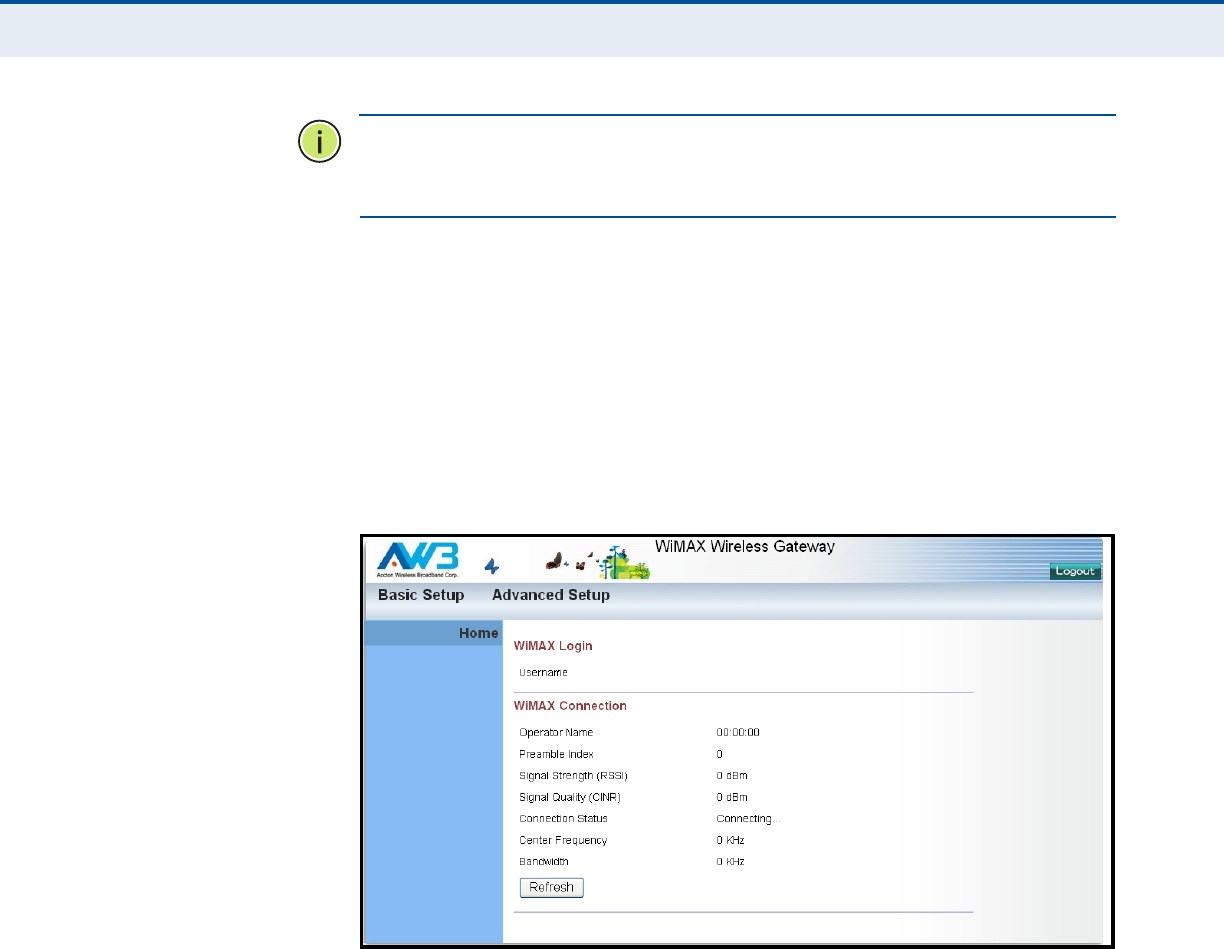
HOME PAGE The home page displays the current status of the WiMAX connection.
To configure basic settings for the current operating mode, click Basic
Setup. For more information, see “Using the Basic Setup Wizard” on
page 24.
Alternatively, to configure more detailed settings, click Advanced Setup.
For more information, see “The Advanced Setup Menu” on page 26.
Figure 8: Home Page
The following parameters are displayed on the home page:
◆Username – Describes the WiMAX network login name.
◆Operator Network – The identity of the operator network.
◆Linked BSID – The identifier of the connected base station.
◆Preamble Index – A number that identifies the sector on the
connected base station.
◆Signal Strength – The current signal strength value of the received
WiMAX radio signal.
◆Signal Quality – An indication of the carrier-to-interference-plus-
noise-ratio (CINR), which measures the strength of the receive signal
compared to other interference and noise.
C
HAPTER
3
| Initial Configuration
Using the Basic Setup Wizard
– 24 –
◆Connection Status – The current status of the WiMAX connection.
◆Central Frequency – The center frequency of the WiMAX signal.
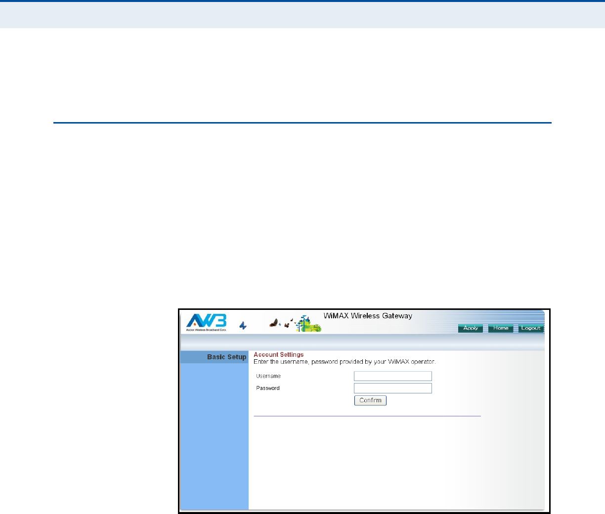
USING THE BASIC SETUP WIZARD
The Basic Setup Wizard takes you through the basic configuration steps for
the RG231.
Launching the Basic Setup Wizard – To perform basic configuration,
click Basic Setup on the home page.
When configuring the unit through the Setup Wizard you will need to
proceed through the following steps:
1. WiMAX Account Login – Configures user authentication settings for
connection to the WiMAX network.
Figure 9: WiMAX Account Login
User Name – The user name required for authentication as provided
by the WiMAX operator. (Default: pseudo@realm)
Password – The user password required for authentication as provided
by the WiMAX operator. (Default: hello)
C
HAPTER
3
| Initial Configuration
Using the Basic Setup Wizard
– 25 –
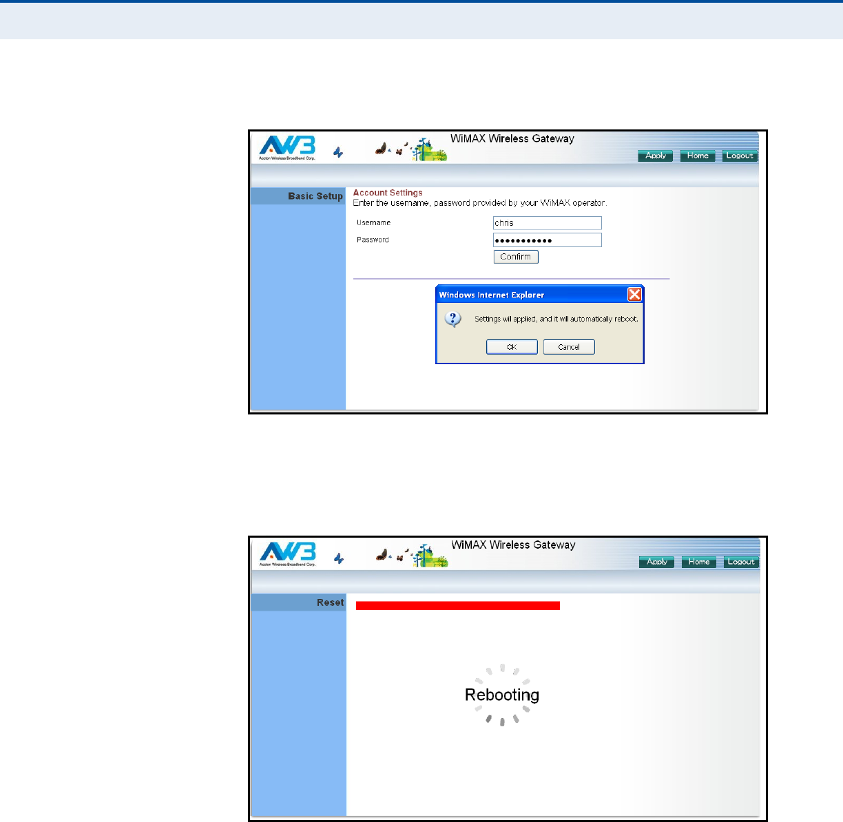
2. Apply Settings – Click “Confirm” to apply the basic settings.
Figure 10: Confirm Settings
3. Basic Setup Finished – When the Basic Setup steps are completed
the unit reboots and attempts to connect to the specified WiMAX
network. Log in again to return to the Home page.
Figure 11: Setup Wizard Finished
C
HAPTER
3
| Initial Configuration
The Advanced Setup Menu
– 26 –
THE ADVANCED SETUP MENU
The Advanced Setup menu provides access to all the configuration settings
available for the RG231.
Figure 12: Advanced Setup
Each primary menu item is sumarized below with links to the relevant
section in this guide where configuration parameters are described in
detail:
◆System – Configures general device settings. See page 28.
◆WAN – Configures WAN settings. See page 28.
◆NAT – Configures Network Address Translation settings. See page 37.
◆Route – Configures static routing settings. See page 40.


– 28 –
4SYSTEM SETTINGS
The RG231’s System menu allows you to perform general management
functions for the unit, including setting the system time, configuring an
access password, and upgrading the system software.
The System pages include the following options.
Table 7: System Settings
Menu Description Page
System Status Displays WAN and LAN interface information and other
system details
29
Administrator Configures user password for management
access
30
Firmware Upgrade Updates the current firmware 31
Configuration Restores the factory default settings, or save the unit’s
current settings
31
System Time Configures the system time settings for updates from a
time server
32
Reset Resets the device 33
C
HAPTER
4
| System Settings
System Status
– 29 –
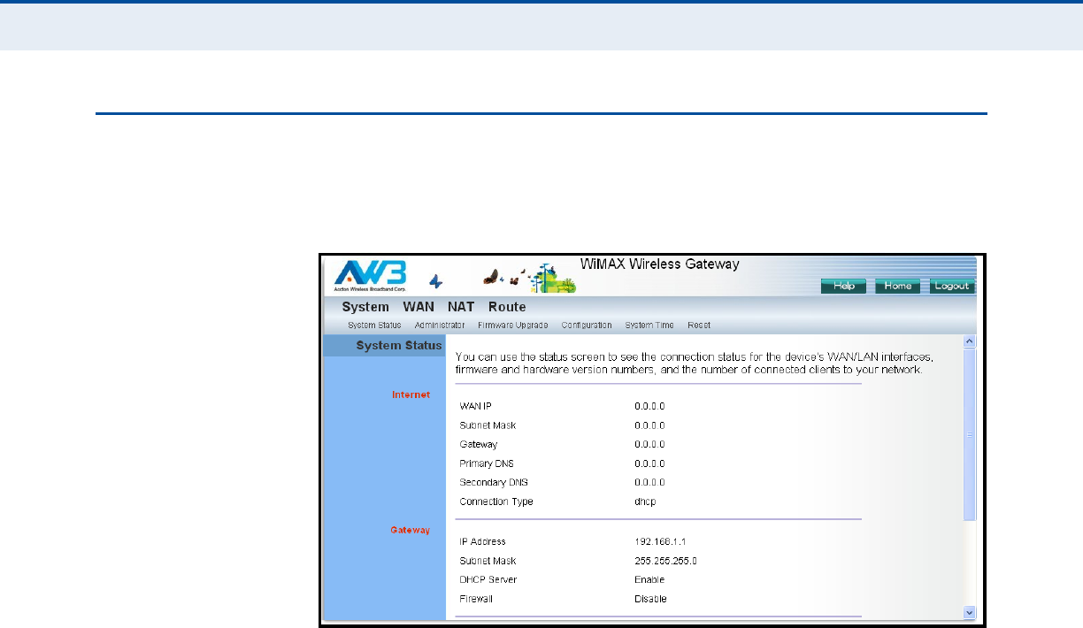
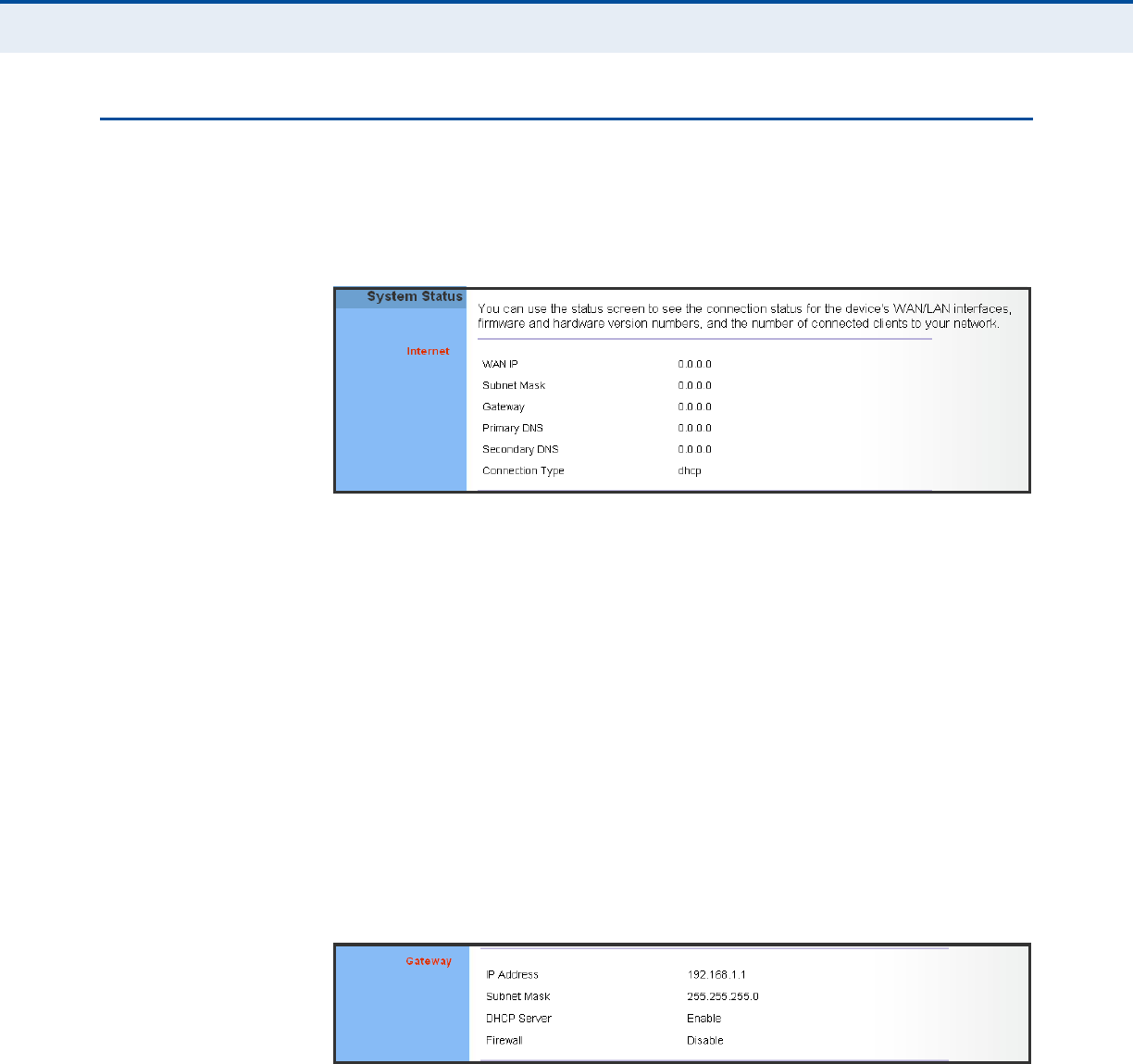
SYSTEM STATUS
The system status page displays connectivity status information for the
unit’s WiMAX (WAN) and LAN interfaces, firmware and hardware version
numbers, and the number of clients connected to your network.
Figure 13: System Status – Internet
INTERNET – Displays WAN (WiMAX) connection status:
◆WAN IP – Displays the IP address assigned by the service provider.
◆Subnet Mask – Displays the WAN subnet mask assigned by the service
provider.
◆Gateway – Displays the WAN gateway address assigned by the service
provider.
◆Primary DNS – Displays the WAN primary DNS address.
◆Secondary DNS – Displays the WAN secondary DNS address.
◆Connection Type – Displays the connection type for the WAN. Either
FIXED for a static IP setting, or DHCPC for dynamic IP assignment.
Figure 14: System Status – Gateway
GATEWAY – Display system IP settings, as well as DHCP, NAT and firewall
status:
◆IP Address – Displays the unit’s IP address.
◆Subnet Mask – Displays the subnet mask.
◆DHCP Server – Displays the DHCP server status.
C
HAPTER
4
| System Settings
Administrator Settings
– 30 –
◆Firewall – Displays the firewall status.
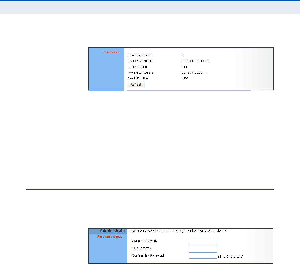
Figure 15: System Status – Information
INFORMATION – Displays the number of connected clients, as well as the
unit’s LAN and WAN MAC addresses:
◆Connected Clients – Displays the number of connected clients, if any.
◆LAN MAC Address – Displays the LAN MAC address.
◆LAN MTU Address – The maximum transmission unit size in bytes.
◆WAN MAC Address – Displays WAN MAC address.
◆WAN MTU Address – The maximum transmission unit size in bytes.
ADMINISTRATOR SETTINGS
The Administrator Settings page enables you to change the default
password for management access to the RG231.
Figure 16: Setting a Password
The following parameters are displayed on this page:
◆Current Password – You need to first enter your current administrator
password to be able to configure a new one. (Default: admin)
◆New Password – Enter a new administrator password. (Range: 3~12
characters)
◆Confirm New Password – Enter the new password again for
verification.
(Range: 3~12 characters)
C
HAPTER
4
| System Settings
Firmware Upgrade
– 31 –
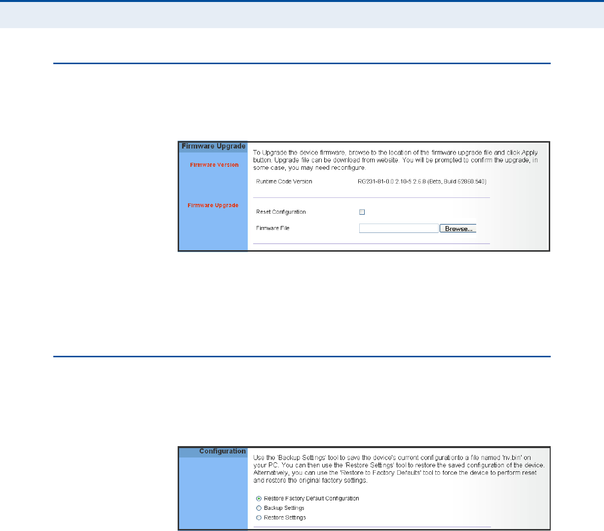
FIRMWARE UPGRADE
The Firmware Upgrade page enables you to download new software to the
unit.
Figure 17: Firmware Upgrade
Firmware Upgrade – Downloads an operation code file from the web
management station to the RG231 using HTTP. Use the Browse button to
locate the code file locally on the management station and check the Reset
Configuration to restore factory defaults. Click Apply to proceed.
CONFIGURATION TOOLS
The Configurations Tools page allows you to restore factory default
settings, or save and restore the unit’s configuration settings to or from a
file on the management station.
Figure 18: Configuration Tools
The following parameters are displayed on this page:
◆Restore Factory Default Configuration – Resets the unit to its
factory default settings. When you select “Restore Factory Default
Configuration” and click Apply, a confirmation page displays. Click OK
to continue.
◆Backup Settings – Saves the current configuration settings to a file on
the web management station.
C
HAPTER
4
| System Settings
System Time
– 32 –
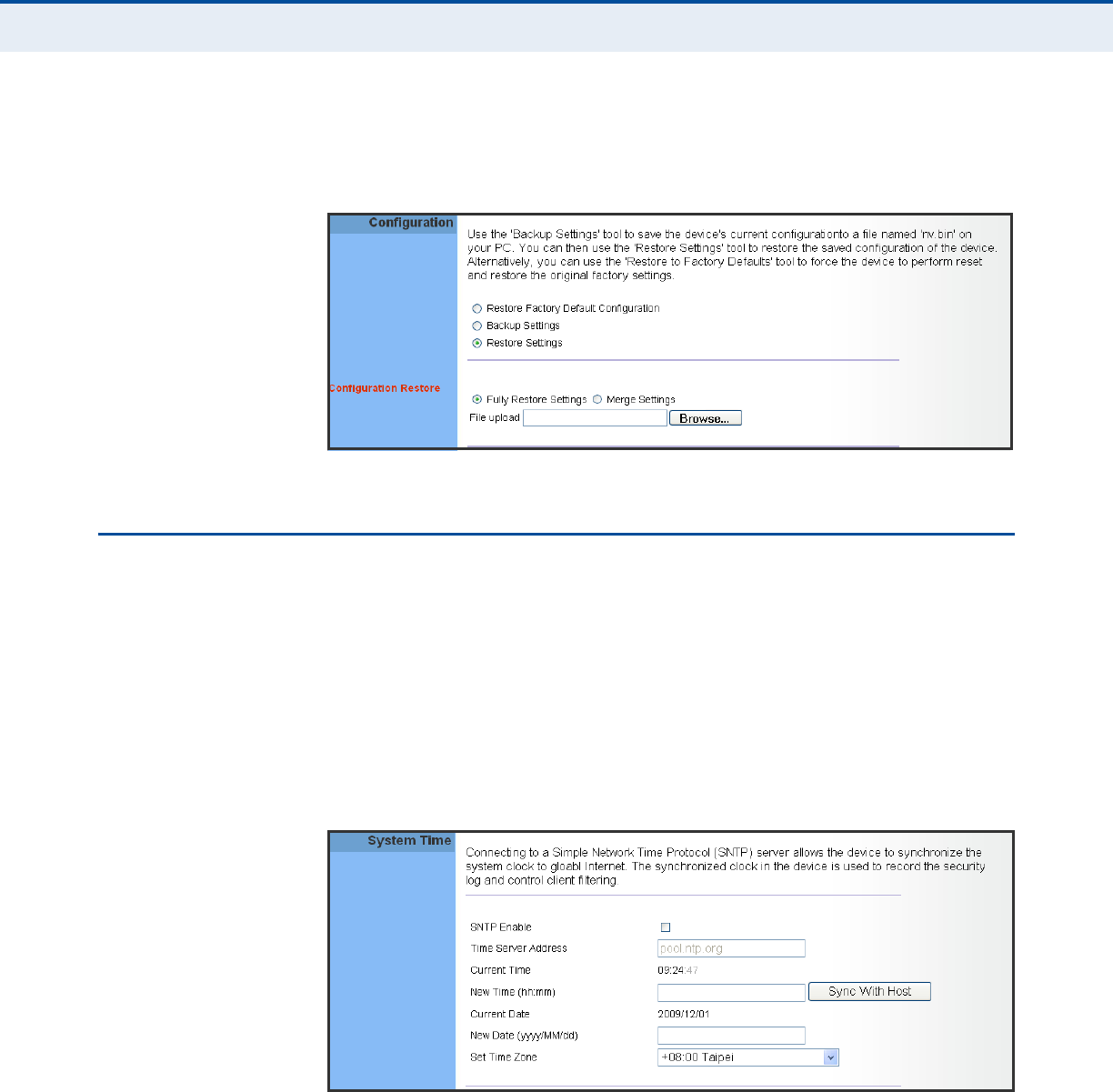
◆Restore Settings – Restores a saved configuration file to the unit. You
can use the Browse button to locate the file on the web management
station.
Figure 19: Restore Configuration Settings
SYSTEM TIME
The RG231 uses the Simple Network Time Protocol (SNTP) to set its
internal clock based on periodic updates from a time server. Maintaining an
accurate time on the device enables the system log to record meaningful
dates and times for event entries.
SNTP uses Coordinated Universal Time (or UTC, formerly Greenwich Mean
Time, or GMT) based on the time at the Earth’s prime meridian, zero
degrees longitude. To display a time corresponding to your local time, you
must select your time zone.
Figure 20: System Time
The following parameters are displayed on this page:
◆SNTP Enable – Enables the unit to set its internal clock based on
periodic updates from a time server. The unit acts as an SNTP client,
periodically sending time synchronization requests to a specified time
server. Alternatively, you can select “None” and set the time and date
manually. (Default: Disabled)
C
HAPTER
4
| System Settings
Reset
– 33 –
◆Time Server Address – The IP address of a time server that the unit
attempts to poll for a time update. (Default: 192.43.244.18)
◆Current Time (hh:mm:ss) – Displays the current time of the system
clock.
◆New Time (hh:mm:ss) – Sets the system clock to the time specified.
◆Sync with host – Sets the unit's time from the web management PC's
system time.
◆Current Date (yyyy:mm:dd) – Displays the current date of the
system clock.
◆New Date (yyyy:mm:dd) – Sets the system clock to the date
specified.
◆Set Time Zone – SNTP uses Coordinated Universal Time (or UTC,
formerly Greenwich Mean Time, or GMT) based on the time at the
Earth’s prime meridian, zero degrees longitude. To display a time
corresponding to your local time, you must select your time zone from
the pull-down list. (Default: (GMT+08:00) Taipei)
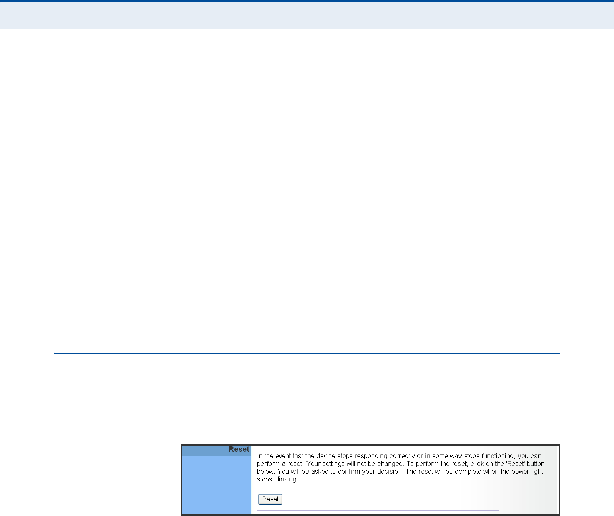
RESET
The Reset page allows you to restart the device’s software. If the unit stops
responding correctly or in some way stops functioning, performing a reset
can clear the condition.
Figure 21: Reset Unit
Reset – Resets the unit. All current settings are retained.

– 34 –
5GATEWAY CONFIGURATION
The information in this chapter covers the configuration options for the
RG231’s Internet gateway functions.
The RG231 provides comprehensive firewall features and NAT isolation for
Internet traffic passing from the WiMAX service provider to the local
network connected to the LAN ports. The DHCP server feature can assign
IP addresses for up to 32 local network PCs and wireless clients.
The Advanced Setup menu includes the following items for Internet
gateway configuration.
Table 8: Gateway Configuration
Menu Description Page
WAN
WAN Settings Sets the connection method of your Internet service
provider
35
DNS Specifies DNS servers that you want to access 37
NAT
Port Forwarding Allows the unit to be configured as a virtual server 37
DMZ Allows clients to connect to the unit directly bypassing the
firewall
39
Route
Routing Table List Displays the routing table 40
C
HAPTER
5
| Gateway Configuration
WAN Settings
– 35 –
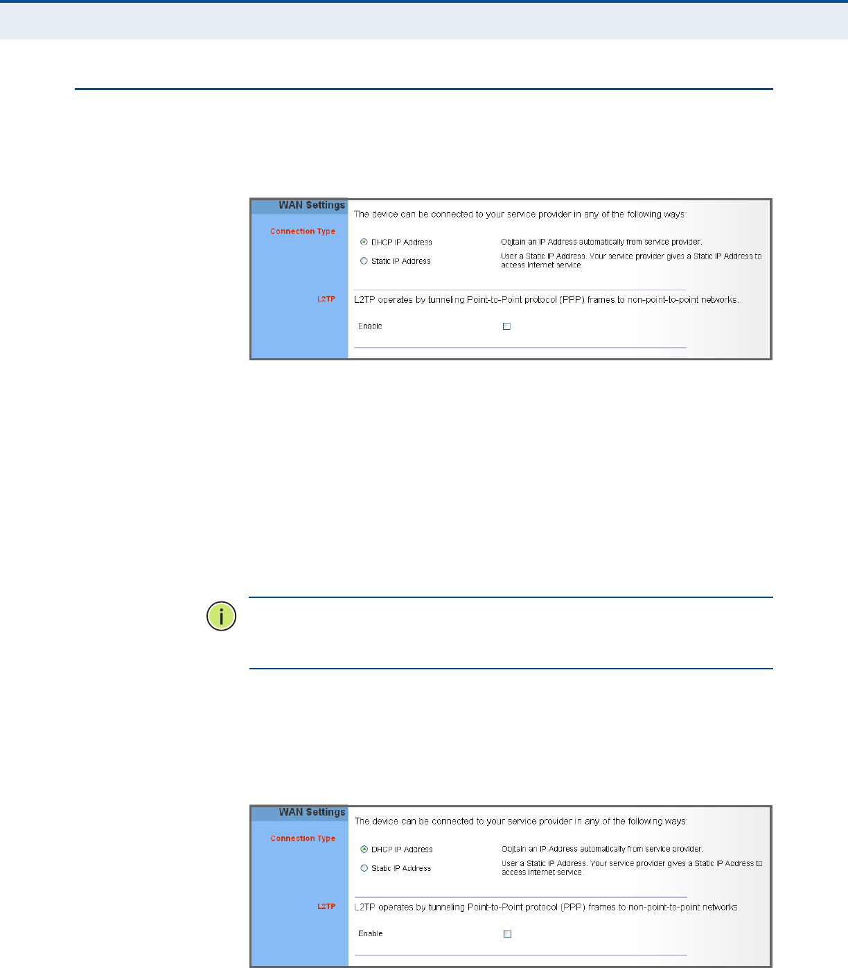
WAN SETTINGS
Select the WAN connection type used by your service provider and specify
DNS (Domain Name System) servers.
Figure 22: WAN Settings
The unit can be connected to your ISP in one of the following ways:
◆DHCP IP Address – Selects configuration for an Internet connection
using DHCP for IP address assignment. This is the default setting.
◆Static IP Address – Selects configuration for an Internet connection
using a fixed IP assignment.
◆L2TP – Selects configuration for an Internet connection using the Layer
2 Tunneling Protocol, an access protocol often used for virtual private
networks.
N
OTE
:
For the Dynamic IP Address (DHCP) option, the unit requires no
further configuration. Selecting other WAN types displays the parameters
that are required for configuring the connection.
DYNAMIC IP ADDRESS For dynamic IP assignment from the service provider, the unit functions as
a Dynamic Host Configuration Protocol (DHCP) client. When enabled, no
other settings are required.
Figure 23: Dynamic IP Address
C
HAPTER
5
| Gateway Configuration
WAN Settings
– 36 –
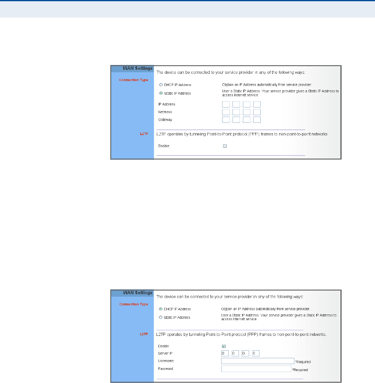
STATIC IP SETTINGS Selecting Static IP Address for the WAN type enables you to enter static IP
settings as assigned by the service provider.
Figure 24: Static IP Settings
The following parameters are displayed in this section on this page:
◆IP Address – The IP address provided by your service provider. Valid
IP addresses consist of four decimal numbers, 0 to 255, separated by
periods.
◆Netmask – Indicates the subnet mask, such as 255.255.255.0.
◆Gateway – The gateway IP address provided by your service provider.
L2TP SETTINGS If your service provider supports Layer 2 Tunneling Protocol (L2TP) for your
Internet connection, configure the settings described below.
Figure 25: L2TP Settings
The following parameters are displayed in this section on this page:
◆Enable – Enables the L2TP settings.
C
HAPTER
5
| Gateway Configuration
NAT
– 37 –
◆Server IP – The IP address of the L2TP server, as specified by the
service provider.
◆Username – Enter your user name for connecting to the L2TP service,
as supplied by the service provider. (Range: 1-20 characters; Default:
No name)
◆Password – Specify the password for your connection, as supplied by
the service provider. (Range: 1-20 characters; Default: No password)
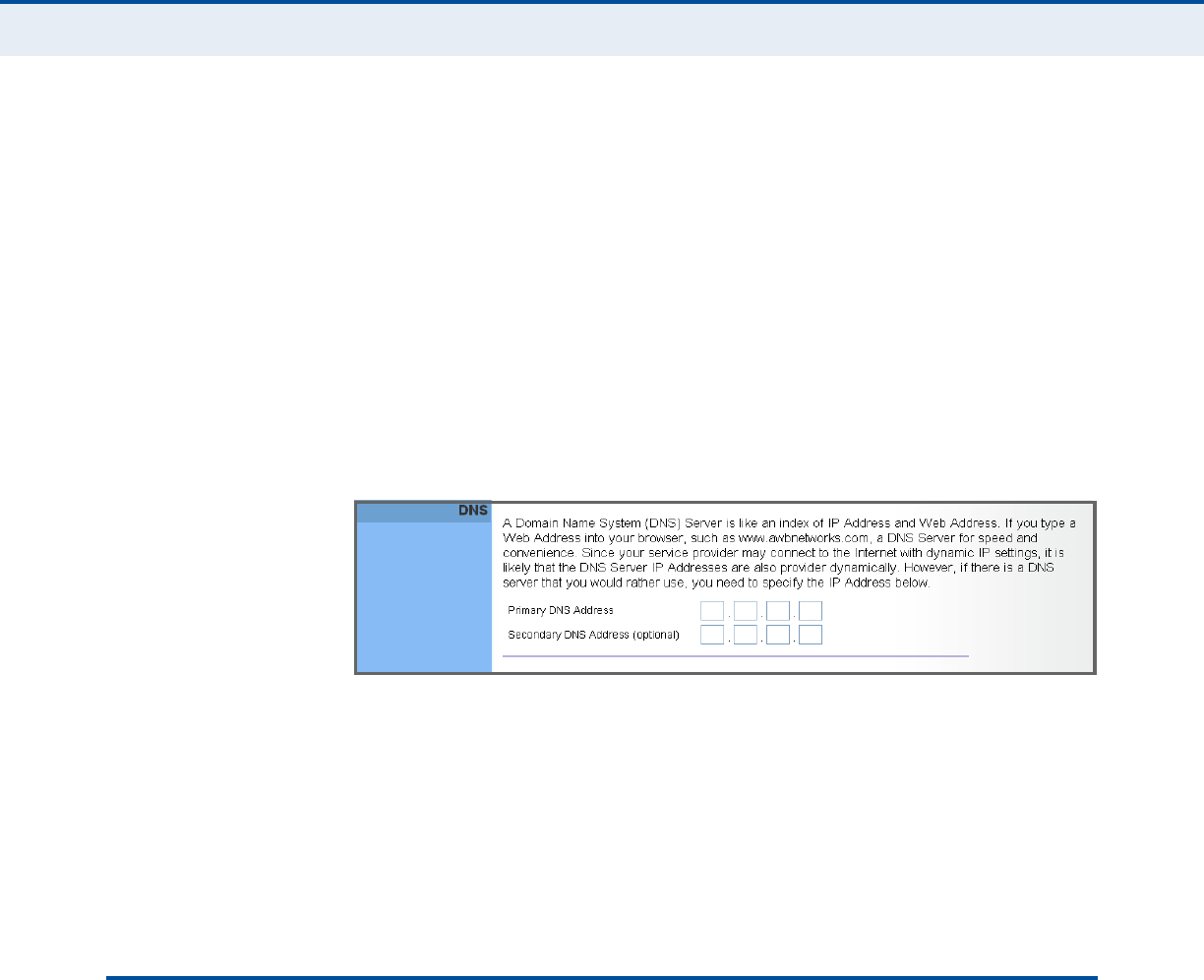
DNS DNS (Domain Name System) server addresses are usually provided by
service providers, however if you want to specify certain servers, the DNS
page enables you to enter primary and secodary DNS addresses.
Figure 26: DNS Settings
The following parameters are displayed on this page:
◆Domain Name Server (DNS) Address – Address of the primary DNS
server, specified in the form of 0.0.0.0. (The default address 0.0.0.0
disables the manual DNS setting.)
◆Secondary DNS Address (optional) – Optional address of a
secondary DNS server, specified in the form of 0.0.0.0.
NAT
Network Address Translation (NAT) is a standard method of mapping
multiple "internal" IP addresses to one "external" IP address on devices at
the edge of a network. For the RG231, the internal (local) IP addresses are
the IP addresses assigned to local PCs by the DHCP server, and the
external IP address is the IP address assigned to the WiMAX interface.
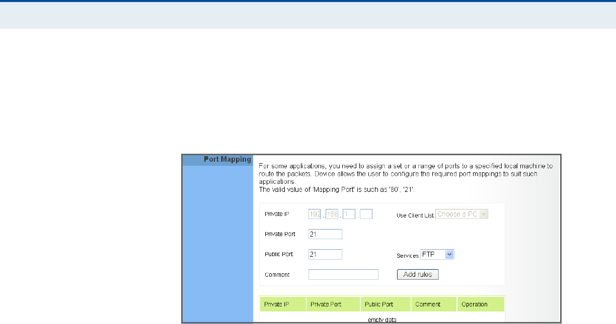
PORT MAPPING Using the NAT Port Mapping feature, remote users can access different
servers on your local network using your single public IP address.
Remote users accessing services such as web or FTP at your local site
thorugh your public IP address, are redirected (mapped) to other local
server IP addresses and TCP/UDP port numbers. For example, if you set
Type/Public Port to TCP/80 (HTTP or web) and the Private IP/Port to
192.168.7.9/80, then all HTTP requests from outside users forwarded to
C
HAPTER
5
| Gateway Configuration
NAT
– 38 –
192.168.7.9 on port 80. Therefore, by just using your external IP address
provided by your ISP, Internet users can access the services they need at
the local addresses to which you redirect them.
The more common TCP service port numbers include: HTTP: 80, FTP: 21,
Telnet: 23, and SSH: 22.
Figure 27: Port Mapping
The following parameters are displayed on this page:
◆Private IP – The IP address of the server on the local Ethernet
network. The specified address must be in the same subnet as the
RG231 and its DHCP server address pool. Alternatively, the IP address
can be set by selecting a PC from the DHCP client list. (Range:
192.168.1.1 to 192.168.1.254)
◆Use Client List – Allows the Private IP to be selected from the DHCP
client list.
◆Private Port – Specifies the TCP/UDP port number used on the local
server for the service. (Range: 1-65535)
◆Public Port – Specifies the public TCP/UDP port used for the service on
the WAN interface. (Range: 1-65535)
◆Services – Specifies port numbers for some of the more common
services. (Options: FTP, SSH, Telnet, SMTP, HTTP, HTTPS)
◆Comment – A text comment for the forwarding rule.
◆Add Rules – Adds the defined rule to the port forwarding table. Use
the Delete button next to a rule to remove it from the table.
C
HAPTER
5
| Gateway Configuration
NAT
– 39 –
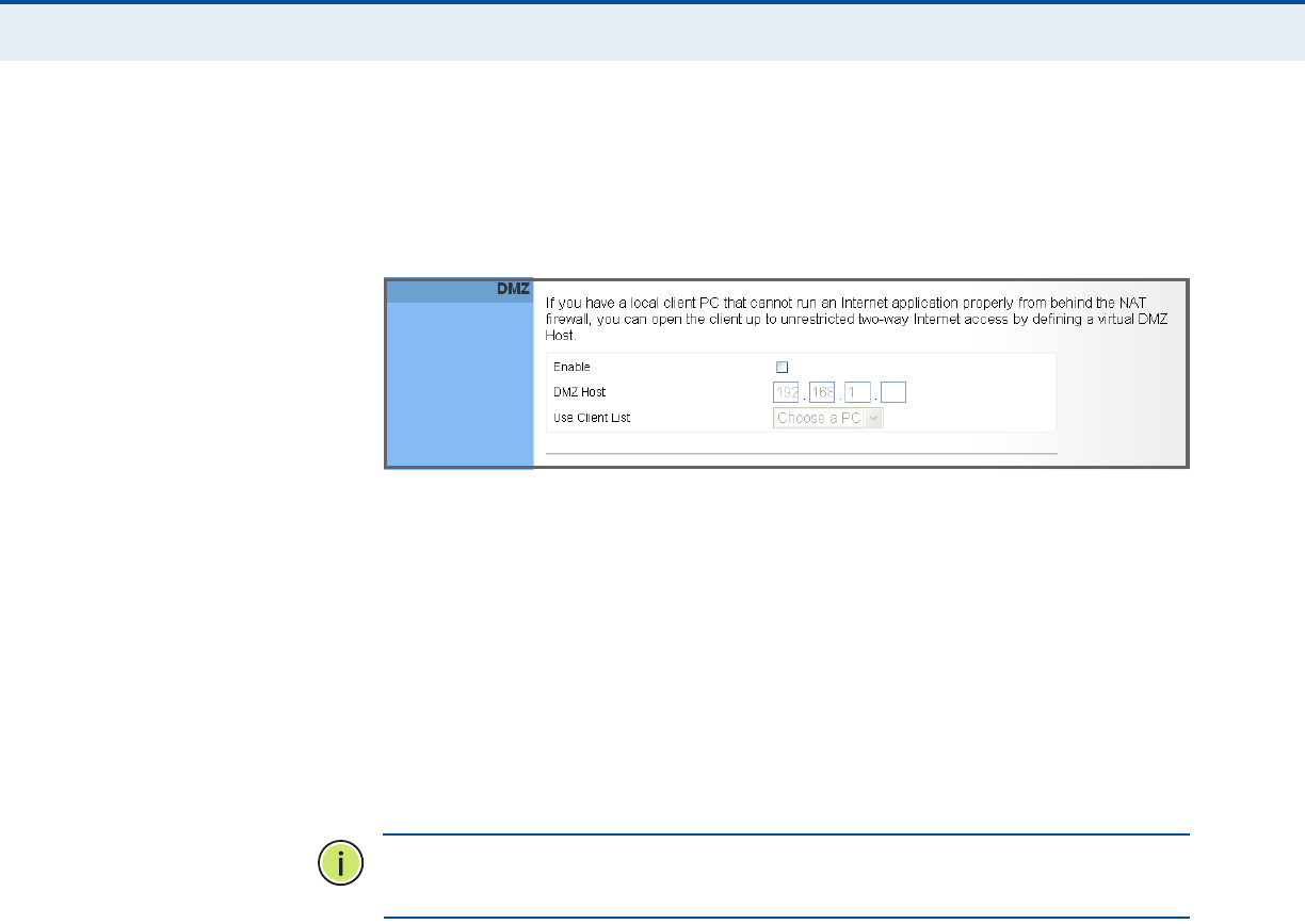
DMZ If you have a client PC that cannot run an Internet application properly
from behind the NAT firewall, you can open the client up to unrestricted
two-way internet access by defining a virtual-DMZ (virtual-demilitarized-
zone) host.
Figure 28: DMZ Settings
The following parameters are displayed on this page:
◆Enable – Enables the feature. (Default: Disabled)
◆DMZ Host – Specifies the IP address of the virtual DMZ host.
Alternatively, the host IP can be set by selecting a PC from the DHCP
client list.
(Range: 192.168.1.1 to 192.168.1.254)
◆Use Client List – Allows the host IP to be selected from the DHCP
client list.
N
OTE
:
Adding a host to the DMZ may expose your local network to a
variety of security risks, so only use this option as a last resort.
C
HAPTER
5
| Gateway Configuration
Route
– 40 –
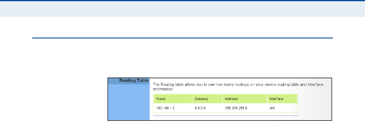
ROUTE
The
Routing Table displays the list of static routes on the unit.
Figure 29: Routing Table
The following parameters are displayed in this section on this page:
◆Route – The IP address that identifies the IP subnet of the remote
network.
◆Gateway – The IP address of the router within the local IP subnet that
forwards traffic to the remote IP subnet.
◆Netmask – The mask that identifies the IP subnet of the remote
network.
◆Interface – Indicates the local network interface on the unit.


– 42 –
ATROUBLESHOOTING
DIAGNOSING LED INDICATORS
CANNOT CONNECT TO THE INTERNET
If you cannot access the Internet from the PC, check the following:
◆If you cannot access the Internet, be sure your Windows system is
correctly configured for TCP/IP. The IP settings should be set to “obtain
an IP address automatically.”
◆You may be out of the service area of the WiMAX network. Check with
the WiMAX service provider for service coverage information.
◆If you cannot resolve the problem, check the System Status page of the
web interface and contact your WiMAX service provider.
Table 9: Troubleshooting Chart
Symptom Action
Power LED is Off ◆AC power adapter may be disconnected. Check
connections between the unit, the AC power adapter,
and the wall outlet.
Power LED is Red ◆The unit has detected a system error. Reboot the unit to
try and clear the condition.
◆If the condition does not clear, contact your local dealer
for assistance.
WiMAX Signal LEDs are Off ◆Move the location of the unit.
◆Check with the WiMAX service provider for service
coverage information.
LAN link LED is Off ◆Verify that the unit and attached device are powered on.
◆Be sure the cable is plugged into both the unit and
corresponding device.
◆Verify that the proper cable type is used and its length
does not exceed specified limits.
◆Check the cable connections for possible defects.
Replace the defective cable if necessary.

A
PPENDIX
A
| Troubleshooting
Cannot Access Web Management
– 43 –
CANNOT ACCESS WEB MANAGEMENT
If the management interface cannot be accessed using a web browser:
◆Be sure the management station is correctly configured for TCP/IP. The
IP settings should be set to “obtain an IP address automatically.”
◆Try a Ping command from the management station to the unit’s IP
address to verify that the entire network path between the two devices
is functioning correctly.
◆Check that the management station has a valid network connection and
that the Ethernet port that you are using has not been disabled.
◆Check the network cabling between the management station and the
unit. If the problem is not resolved, try using a different port or a
different cable.
FORGOT OR LOST THE PASSWORD
Set the unit to its default configuration by pressing the reset button on the
base for 5 seconds or more. Then use the default password “admin” to
access the management interface.
RESETTING THE UNIT
If all other recovery measures fail and the unit is still not functioning
properly, take either of these steps:
◆Reset the unit using the web interface, or through a power reset.
◆Reset the unit to its factory default configuration by pressing the reset
button on the base for 5 seconds or more. Then use the default
password “admin” to access the management interface.

– 44 –
BHARDWARE SPECIFICATIONS
PHYSICAL SPECIFICATIONS
PORTS 4 LAN ports, 10/100BASE-TX with auto-negotiation, RJ-45 connector
(Optional) 2 FXS ports (PHONE1, PHONE2), RJ-11 connector
NETWORK INTERFACE RJ-45 connector, auto MDI/X:
10BASE-T: RJ-45 (100-ohm, UTP cable; Category 3 or better)
100BASE-TX: RJ-45 (100-ohm, UTP cable; Category 5 or better)
LED INDICATORS System: Power, WiMAX signal strength, WiFi, WPS
Ports: Link/Activity
AC POWER ADAPTER Input: 100-240 VAC, 50-60 Hz, 1 A maximum
Output: 12 VDC, 2 A
UNIT POWER SUPPLY DC Input: 12 VDC, 1.5 A maximum
Power Consumption: 18 W maximum
PHYSICAL SIZE 181.5 x 198.5 x 79 mm (7.15 x 7.81 x 3.11 in)
WEIGHT 412 g (14.5 oz)
TEMPERATURE Operating: -5 to 45 °C (23 to 113 °F)
Storage: -40 to 75 °C (-40 to 167 °F)
HUMIDITY 5% to 95% (non-condensing)

A
PPENDIX
B
| Hardware Specifications
WiMAX Specifications
– 45 –
WIMAX SPECIFICATIONS
ANTENNAS Pattern: Omnidirectional
Transmit and Receive: One transmit and two receive with Maximal-Ratio
Combining (MRC). Support for transmitter diversity.
Gain: 6 dBi
Impedance: 50 Ohm
OPERATING FREQUENCY FCC-2.5: 2496-2690 MHz
Taiwan NCC: 2500-2690 MHz
Support for Full Scan and Partial Scan
CHANNEL BANDWIDTH 2.5 GHz model: 5 and 10 MHz
MODULATION SCHEME Scaleable OFDMA employing Time-Division Duplex (TDD) mechanism
PRBS subcarrier randomization
Contains pilot, preamble, and ranging modulation
MODULATION AND
CODING TYPES
Down Link: QPSK, 16 QAM, 64 QAM
Up Link: QPSK, 16 QAM
RECEIVE SENSITIVITY -94 dBm maximum
VOIP SPECIFICATIONS
VOICE SIGNALING
PROTOCOL
SIP v2 (RFC 3261)
VOICE CODEC G.711 (a-law and u-law)
G.726
G.729ab
G.723.1
VOICE QUALITY VAD (Voice Activity Detection)
CNG (Comfortable Noise Generation)

A
PPENDIX
B
| Hardware Specifications
Wi-Fi Specifications
– 46 –
Echo cancellation (G.165/G.168)
Adaptive jitter buffer, up to 200 milliseconds
DTMF tone detection and generation
CALL FEATURES Caller ID number and name
Caller ID Block
Call transfer
Call waiting/hold/retrieve
3-way conference call
Call blocking
T.38 fax relay
Dial plan (E.164 dialing plan)
Call forwarding: No Answer/Busy/All
REN (RING EQUIVALENT
NUMBER)
3 REN total in system
WI-FI SPECIFICATIONS
MAXIMUM 802.11B/G
CHANNELS
FCC/IC/NCC: 1-11
ETSI: 1-13
France: 10-13
MKK: 1-14
OPERATING FREQUENCY 2.4 ~ 2.4835 GHz (US, Canada, ETSI)
2.4 ~ 2.497 GHz (Japan)
MODULATION TYPE 802.11n: BPSK, QPSK, OFDM
802.11g: BPSK, QPSK, OFDM
802.11b: CCK, BPSK, QPSK
RF OUTPUT POWER 802.11b: 22.5 dBm
802.11g: 22.5 dBm
802.11n: 22.5 dBm
RF RECEIVE SENSITIVITY 802.11b: -85 dBm @ 11 Mbps
802.11g: -65 dBm @ 54 Mbps
802.11n: -61 dBm @ 150 Mbps

A
PPENDIX
B
| Hardware Specifications
Compliances
– 47 –
COMPLIANCES
EMISSIONS FCC CFR 47 Part 15 Class B
EN 55022 class B
EN 301 489-1/4/17
EMMUNITY EN 61000-4-2/3/4/5/6/8/11
WIMAX RADIO SIGNAL
CERTIFICATION
US: 2.3 GHz - FCC CFR 47 Part 27D; 2.5 GHz - CFR 47 Part 27M/ Part
25.254
Europe (3.5 GHz): EN 302 326-2 (V1.2.2), EN 302 326-3 (V1.2.2)
NCC: PLMN09
WI-FI RADIO SIGNAL
CERTIFICATION
FCC CFR 47 Part 15 Subpart C
EN 300 328
NCC: LP0002
SAFETY CE: EN 60950-1 (LVD)
NCC: CNS14336
STANDARDS IEEE 802.16e-2005 WAVE 1 and WAVE 2
IEEE 802.3-2005 10BASE-T and 100BASE-TX
IEEE 802.11b, 802.11g, and 802.11n
– 48 –
CCABLES AND PINOUTS
TWISTED-PAIR CABLE ASSIGNMENTS
For 10/100BASE-TX connections, a twisted-pair cable must have two pairs
of wires. Each wire pair is identified by two different colors. For example,
one wire might be green and the other, green with white stripes. Also, an
RJ-45 connector must be attached to both ends of the cable.
C
AUTION
:
Each wire pair must be attached to the RJ-45 connectors in a
specific orientation. (See “Straight-Through Wiring” on page 49 and
“Crossover Wiring” on page 50 for an explanation.)
C
AUTION
:
DO NOT plug a phone jack connector into the RJ-45 port. Use
only twisted-pair cables with RJ-45 connectors that conform with FCC
standards.
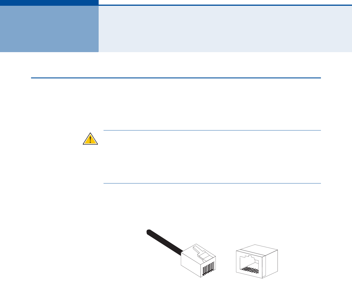
The following figure illustrates how the pins on the RJ-45 connector are
numbered. Be sure to hold the connectors in the same orientation when
attaching the wires to the pins.
Figure 30: RJ-45 Connector
10/100BASE-TX PIN
ASSIGNMENTS
Use unshielded twisted-pair (UTP) or shielded twisted-pair (STP) cable for
RJ-45 connections: 100-ohm Category 3 or better cable for 10 Mbps
connections, or 100-ohm Category 5 or better cable for 100 Mbps
connections. Also be sure
that the length of any twisted-pair connection
does not exceed 100 meters (328 feet).
The RJ-45 ports on the unit supports automatic MDI/MDI-X operation, so
you can use straight-through or crossover cables for all network
connections to PCs, switches, or hubs. In straight-through cable, pins 1, 2,
3, and 6, at one end of the cable, are connected straight through to pins 1,
2, 3, and 6 at the other end of the cable.
1
881
A
PPENDIX
C
| Cables and Pinouts
Twisted-Pair Cable Assignments
– 49 –
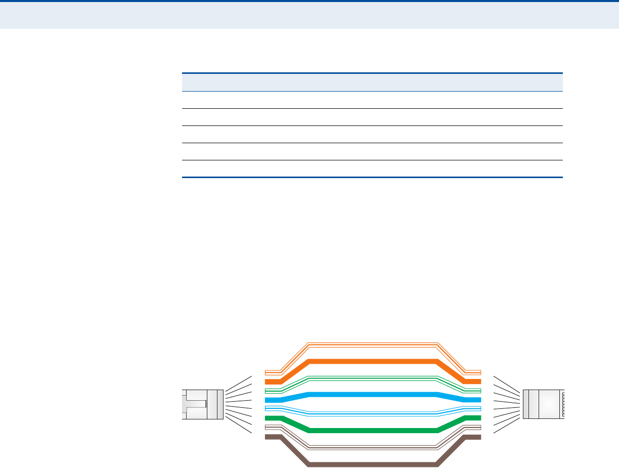
STRAIGHT-THROUGH
WIRING
If the twisted-pair cable is to join two ports and only one of the ports has
an internal crossover (MDI-X), the two pairs of wires must be straight-
through.
Figure 31: Straight Through Wiring
Table 10: 10/100BASE-TX MDI and MDI-X Port Pinouts
PIN MDI Signal Namea
a. The “+” and “-” signs represent the polarity of the wires that make up each wire pair.
MDI-X Signal Name
1 Transmit Data plus (TD+) Receive Data plus (RD+)
2 Transmit Data minus (TD-) Receive Data minus (RD-)
3 Receive Data plus (RD+) Transmit Data plus (TD+)
6 Receive Data minus (RD-) Transmit Data minus (TD-)
4, 5, 7, 8 Not used Not used
White/Orange Stripe
Orange
White/Green Stripe
Green
1
2
3
4
5
6
7
8
1
2
3
4
5
6
7
8
EIA/TIA 568B RJ-45 Wiring Standard
10/100BASE-TX Straight-through Cable
End A End B
Blue
White/Blue Stripe
Brown
White/Brown Stripe
A
PPENDIX
C
| Cables and Pinouts
Twisted-Pair Cable Assignments
– 50 –
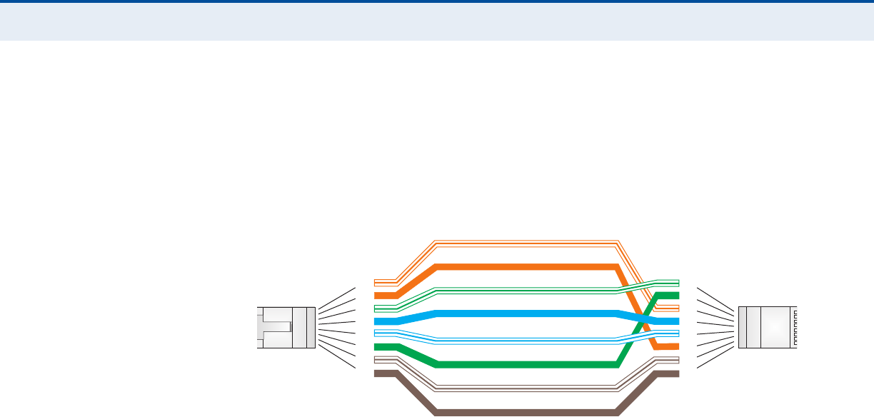
CROSSOVER WIRING If the twisted-pair cable is to join two ports and either both ports are
labeled with an “X” (MDI-X) or neither port is labeled with an “X” (MDI), a
crossover must be implemented in the wiring.
Figure 32: Crossover Wiring
White/Orange Stripe
Orange
White/Green Stripe
1
2
3
4
5
6
7
8
1
2
3
4
5
6
7
8
EIA/TIA 568B RJ-45 Wiring Standard
10/100BASE-TX Crossover Cable
End A End B
Green
Blue
White/Blue Stripe
Brown
White/Brown Stripe
A
PPENDIX
C
| Cables and Pinouts
RJ-11 Ports
– 51 –
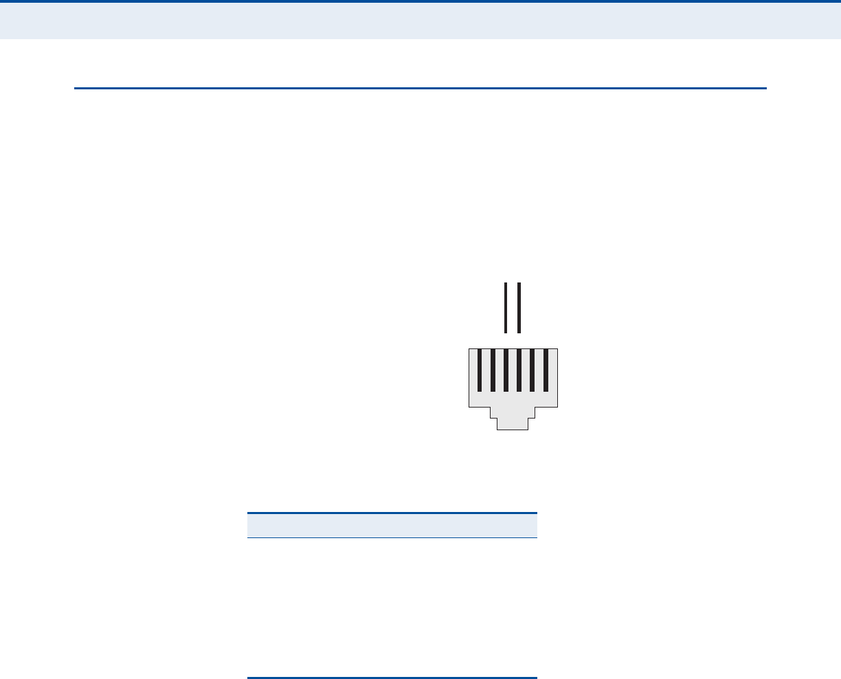
RJ-11 PORTS
Standard telephone RJ-11 connectors and cabling can be found in several
common wiring patterns. These six-pin connectors can accommodate up to
three wire pairs (three telephone lines), but usually only one or two pairs
of conductor pins and wires are implemented.
The RJ-11 ports on this device contain only one wire pair on the inner pins
(3 and 4).
Figure 33: RJ-11 Port Pinout
Table 11: RJ-11 Port Pinout
Pin Signal Name Wire Color
1Not used
2Not used
3 Line 1 Ring Red or Blue/White
4 Line 1 Tip Green or White/Blue
5Not used
6Not used
123456
Red or
Blue/White
Green or
White/Blue
RT
R = Ring T = Tip

– 52 –
GLOSSARY
10BASE-T IEEE 802.3-2005 specification for 10 Mbps Ethernet over two pairs of
Category 3 or better UTP cable.
100BASE-TX IEEE 802.3-2005 specification for 100 Mbps Fast Ethernet over two pairs of
Category 5 or better UTP cable.
ACCESS POINT An Wi-Fi internetworking device that seamlessly connects wired and
wireless networks.
AUTHENTICATION The process to verify the identity of a client requesting network access.
AUTO-NEGOTIATION Signalling method allowing each node to select its optimum operational
mode (speed and duplex mode) based on the capabilities of the node to
which it is connected.
BASE STATION A WIMAX service provider’s equipment that is installed at a fixed location
to provide network connectivity for subscriber stations within a defined
service area.
BEACON A signal periodically transmitted from a Wi-Fi access point that is used to
identify the network and maintain contact with wireless clients.
CINR Carrier-to-Interference-Plus-Noise Ratio. A measurement of the channel
quality in a WiMAX link. Subscriber stations measure the received CINR
and send the information back to the base station. The base station can
then adjust modulation and coding for the link to optimize throughput.
CENTER FREQUENCY The radio frequency at the center of a WiMAX channel. WiMAX channels
can be of different widths (the channel bandwidth) and the transmitted
radio signal is spread across the full width of the channel.
CHANNEL BANDWIDTH The range of frequencies occupied by a WiMAX radio signal. The amount of
information that can be transmitted in a radio signal is related to the
channel bandwidth, which is measured in Megahertz (MHz). WiMAX
supports a range of channel bandwidths that can be defined by the service

G
LOSSARY
– 53 –
operator depending on performance requirements, operating preferences,
and regulatory constraints.
CPE Customer-Premises Equipment. Terminal equipment provided by a service
provider that is located at a subscriber’s premises and supports a
communication channel between a customer and the service provider.
DNS Domain Name System. A system used for translating host names for
network nodes into IP addresses.
DHCP Dynamic Host Configuration Protocol. Provides a framework for passing
configuration information to hosts on a TCP/IP network. DHCP is based on
the Bootstrap Protocol (BOOTP), adding the capability of automatic
allocation of reusable network addresses and additional configuration
options.
ENCRYPTION Data passing between a base station and subscribers uses encryption to
protect from interception and evesdropping.
ETHERNET A popular local area data communications network, which accepts
transmission from computers and terminals.
EAP Extensible Authentication Protocol. An authentication protocol used to
authenticate subscribers. EAP is used with TLS or TTLS authentication to
provide “mutual authentication” between a subscriber and a WiMAX
network.
HTTP Hypertext Transfer Protocol. HTTP is a standard used to transmit and
receive all data over the World Wide Web.
ICMP Internet Control Message Protocol. A network layer protocol that reports
errors in processing IP packets. ICMP is also used by routers to feed back
information about better routing choices.
IEEE 802.11BThe Wi-Fi wireless standard that supports communications in the 2.4 GHz
band using Direct Sequence Spread Spectrum (DSSS). The standard
provides for data rates of 1, 2, 5.5, and 11 Mbps.
IEEE 802.11GThe Wi-Fi wireless standard that supports communications in the 2.4 GHz
band using using Orthogonal Frequency Division Multiplexing (OFDM). The
standard provides for data rates of 6, 9, 11, 12, 18, 24, 36, 48, 54 Mbps.
IEEE 802.11g is also backward compatible with IEEE 802.11b.

G
LOSSARY
– 54 –
IEEE 802.16EThe WiMAX standard that provides mobile broadband wireless access using
Scalable Orthogonal Frequency Division Multiple Access (SOFDMA).
IEEE 802.1X Port Authentication controls access to the switch ports by requiring users to
first enter a user ID and password for authentication.
IP ADDRESS The Internet Protocol (IP) address is a numerical identification assigned to
a device that communicates in a network using the Internet Protocol.
ISP Internet Service Provider. A company that offers an access service that
connects customers to the Internet.
LED Light emitting diode. Used for indicating a device or network condition.
LAN Local Area Network. A group of interconnected computer and support
devices.
MAC ADDRESS The physical layer address used to uniquely identify network nodes.
MS-CHAPV2 Microsoft’s version 2 of the Challenge-Handshake Authentication Protocol.
Introduced by Microsoft with Windows 2000, MS-CHAPV2 (defined in RFC
2759) provides mutual authentication between peers using user names
and passwords.
ODFM Orthogonal Frequency Division Multiplexing. The air interface defined for
IEEE 802.11g Wi-Fi. OFDM allows multiple users to transmit in an allocated
band by dividing the bandwidth into many narrow bandwidth carriers.
RADIUS Remote Authentication Dial-in User Service. A logon authentication
protocol that uses software running on a central server to control access to
a network.
RJ-45 CONNECTOR A connector for twisted-pair wiring.
RSSI Receive Signal Strength Indicator. A measurement of the strength of a
received wireless signal. The higher the RSSI value, the stronger the
received signal from the antenna.
ROAMING The process where a WiMAX subscriber can move onto another operator’s
network while maintaining a continuous connection.

G
LOSSARY
– 55 –
SOFDMA Scalable Orthogonal Frequency Division Multiple Access. The air interface
defined for mobile WiMAX. SOFDMA is a multiple access method that allows
simultaneous transmissions to and from several users, employing a
subchannel structure that scales with bandwidth.
SERVICE PROVIDER See Internet Service Provider.
SSID Service Set Identifier. A name that is sent in packets over a Wi-Fi network,
which functions as a password for clients connecting to the network. The
SSID differentiates one Wi-Fi network from another.
SNTP Simple Network Time Protocol. SNTP allows a device to set its internal
clock based on periodic updates from a Network Time Protocol (NTP)
server. Updates can be requested from a specific NTP server, or can be
received via broadcasts sent by NTP servers.
SIM Subscriber Identity Module. A standard for a small removable integrated
circuit card that securely stores information used to identify a mobile
wireless subscriber.
SUBSCRIBER STATION A general term for a customer’s WIMAX terminal equipment that provides
connectivity with a base station.
TCP/IP Transmission Control Protocol/Internet Protocol. Protocol suite that
includes TCP as the primary transport protocol, and IP as the network layer
protocol.
TLS Transport Layer Security. An standard defined in RFC 5216, EAP-TLS is an
authentication protocol that provides strong security through the use of
client-side certificates.
TTLS Tunneled Transport Layer Security. EAP-TTLS is a protocol extension of
EAP-TLS. The authentication server is authenticated to the client using its
Certification Authority certificate, this establishes a secure “tunnel”
through which the client is then authenticated.
URL Uniform Resource Locator. An easy-to-read character string that is used to
represent a resource available on the Internet. For example, “http://
www.url-example.com/.”
UTP Unshielded twisted-pair cable.

G
LOSSARY
– 56 –
WPA Wi-Fi Protected Access. WPA employs IEEE 802.1X as its basic framework
for user authentication and dynamic key management to provide an
enhanced security solution for 802.11 Wi-Fi networks.
WEP Wired Equivalent Privacy. WEP is the Wi-Fi security based on the use of
RC4 encryption keys. Wi-Fi devices without a valid WEP key are excluded
from the network.
PSK WPA Pre-shared Key. PSK security can be used for small Wi-Fi networks
that may not have the resources to configure and maintain a RADIUS
server. WPA provides a simple operating mode that uses just a pre-shared
password for network access.
WIMAX The IEEE 802.16 standard for Worldwide Interoperability for Microwave
Access. The IEEE 802.16-2004 standard, known as “fixed WiMAX,”
supports only point-to-point links and has no support for mobility. The IEEE
802.16e-2005 standard, known as “mobile WiMAX,” is an amendment to
IEEE 802.16-2004 and supports mobility. Note that mobile WiMAX standard
is not backward compatible with the fixed WiMAX standard.

– 57 –
INDEX
A
AC power adapter 17
administrator password, setting 30
administrator settings 30
Advanced Setup menu 26
auto-logout time 31
B
button, Reset 18
C
cable assignments 48
cable connections 20
channels, maximum 46
checklist 19
configuration, basic 24
contents, package 19
D
default settings, restore 31
defaults, factory 31
DNS 37
downloading software 31
dynamic IP, cable modem 35
E
Ethernet ports 17
F
factory defaults, restoring 31
firmware update 31
fixed-IP xDSL 35
G
Gateway address 36, 40
gateway function 20
H
hardware, description 14
I
initial configuration 22
installation, connecting cables 20
installing the device 19
Internet gateway settings 34
IP address 36
L
L2TP 35
LAN status information 29
language selection 22
LEDs 15, 16, 17
login, web 22
lost password, recovery 43
M
MDI/MDI-X, automatic 17
O
operating frequency 45, 46
P
package checklist 19
panels, front and rear 14
password, setting 30
port indicators 15, 16, 17
power socket 17
power supply, specifications 44
private IP 38
private port 38
R
rear panel sockets 17
reboot unit 33, 43
Reset button 18
resetting the unit 33, 43
RJ-45 ports 17
S
Setup Wizard
launching 24
Simple Network Time Protocol See SNTP

I
NDEX
– 58 –
SNTP 32
enabling client 32
software update 31
subnet mask 36, 40
subscriber station 13
system clock, setting 32
system indicators 15, 16
system information 30
system time 32
T
time updates 32
U
upgrading software 31
W
WAN connection type 29
web management interface
access 22
login 22
troubleshooting 43
Wizard, setup 24

RG231
E022010-CS-R01
**************