Accton Wireless Broand FW181RG30000W WiMAX 802.16e Indoor Gateway User Manual user guide
Accton Wireless Broadband Corp. WiMAX 802.16e Indoor Gateway user guide
UserManual.wiki
>
Accton Wireless Broand
>
FW181RG30000W User Manual
User Manual
Navigation menu
Upload a User Manual
Namespaces
Wiki Guide
HTML
PDF
Info
Views
User Manual
Discussion / Help
Navigation
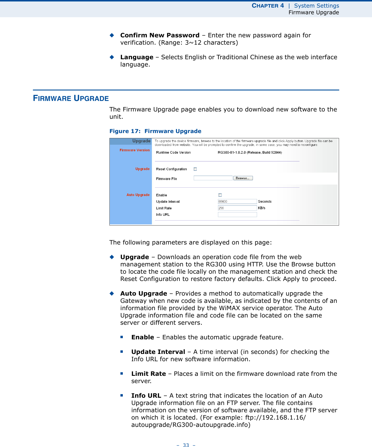
![0560 Česky [Czech] [Jméno výrobce] tímto prohlašuje, že tento [typ zařízení] je ve shodě se základními požadavky a dalšími příslušnými ustanoveními směrnice 1999/5/ES. Dansk [Danish] Undertegnede [fabrikantens navn] erklærer herved, at følgende udstyr [udstyrets typebetegnelse] overholder de væsentlige krav og øvrige relevante krav i direktiv 1999/5/EF. Deutsch [German] Hiermit erklärt [Name des Herstellers], dass sich das Gerät [Gerätetyp] in Übereinstimmung mit den grundlegenden Anforderungen und den übrigen einschlägigen Bestimmungen der Richtlinie 1999/5/EG befindet. Eesti [Estonian] Käesolevaga kinnitab [tootja nimi = name of manufacturer] seadme [seadme tüüp = type of equipment] vastavust direktiivi 1999/5/EÜ põhinõuetele ja nimetatud direktiivist tulenevatele teistele asjakohastele sätetele. English Hereby, [name of manufacturer], declares that this [type of equipment] is in compliance with the essential requirements and other relevant provisions of Directive 1999/5/EC. Español [Spanish] Por medio de la presente [nombre del fabricante] declara que el [clase de equipo] cumple con los requisitos esenciales y cualesquiera otras disposiciones aplicables o exigibles de la Directiva 1999/5/CE. Ελληνική [Greek] ΜΕ ΤΗΝ ΠΑΡΟΥΣΑ [name of manufacturer] ΔΗΛΩΝΕΙ ΟΤΙ [type of equipment] ΣΥΜΜΟΡΦΩΝΕΤΑΙ ΠΡΟΣ ΤΙΣ ΟΥΣΙΩΔΕΙΣ ΑΠΑΙΤΗΣΕΙΣ ΚΑΙ ΤΙΣ ΛΟΙΠΕΣ ΣΧΕΤΙΚΕΣ ΔΙΑΤΑΞΕΙΣ ΤΗΣ ΟΔΗΓΙΑΣ 1999/5/ΕΚ. Français [French] Par la présente [nom du fabricant] déclare que l'appareil [type d'appareil] est conforme aux exigences essentielles et aux autres dispositions pertinentes de la directive 1999/5/CE. Italiano [Italian] Con la presente [nome del costruttore] dichiara che questo [tipo di apparecchio] è conforme ai requisiti essenziali ed alle altre disposizioni pertinenti stabilite dalla direttiva 1999/5/CE. Latviski [Latvian] Ar šo [name of manufacturer / izgatavotāja nosaukums] deklarē, ka [type of equipment / iekārtas tips] atbilst Direktīvas 1999/5/EK būtiskajām prasībām un citiem ar to saistītajiem noteikumiem. Lietuvių [Lithuanian] Šiuo [manufacturer name] deklaruoja, kad šis [equipment type] atitinka esminius reikalavimus ir kitas 1999/5/EB Direktyvos nuostatas. Nederlands [Dutch] Hierbij verklaart [naam van de fabrikant] dat het toestel [type van toestel] in overeenstemming is met de essentiële eisen en de andere relevante bepalingen van richtlijn 1999/5/EG. Malti [Maltese] Hawnhekk, [isem tal-manifattur], jiddikjara li dan [il-mudel tal-prodott] jikkonforma mal-ħtiġijiet essenzjali u ma provvedimenti oħrajn relevanti li hemm fid-Dirrettiva 1999/5/EC. Magyar [Hungarian] Alulírott, [gyártó neve] nyilatkozom, hogy a [... típus] megfelel a vonatkozó alapvetõ követelményeknek és az 1999/5/EC irányelv egyéb elõírásainak.](https://usermanual.wiki/Accton-Wireless-Broand/FW181RG30000W/User-Guide-1456345-Page-5.png)
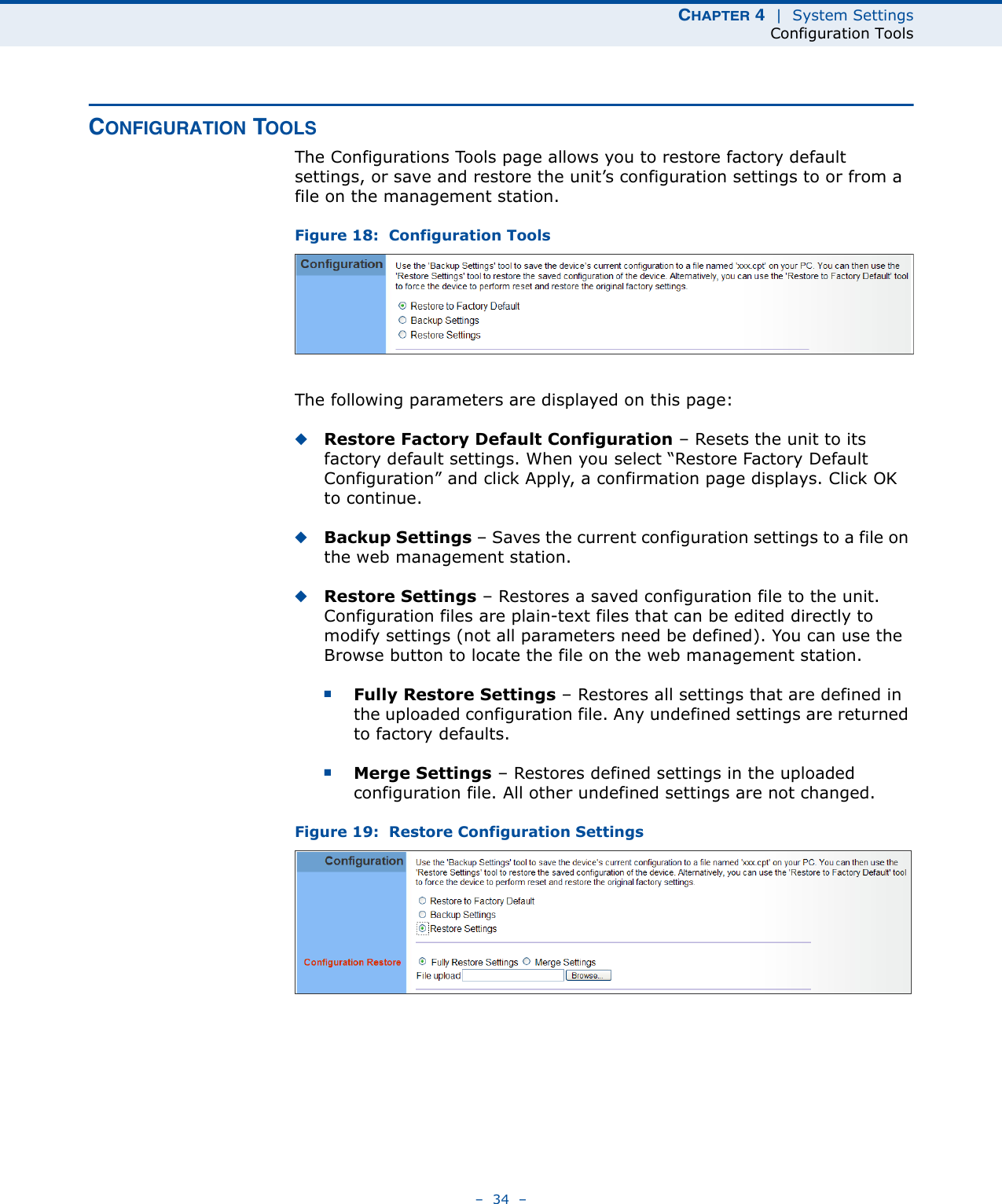
![Polski [Polish] Niniejszym [nazwa producenta] oświadcza, że [nazwa wyrobu] jest zgodny z zasadniczymi wymogami oraz pozostałymi stosownymi postanowieniami Dyrektywy 1999/5/EC. Português [Portuguese] [Nome do fabricante] declara que este [tipo de equipamento] está conforme com os requisitos essenciais e outras disposições da Directiva 1999/5/CE. Slovensko [Slovenian] [Ime proizvajalca] izjavlja, da je ta [tip opreme] v skladu z bistvenimi zahtevami in ostalimi relevantnimi določili direktive 1999/5/ES. Slovensky [Slovak] [Meno výrobcu] týmto vyhlasuje, že [typ zariadenia] spĺňa základné požiadavky a všetky príslušné ustanovenia Smernice 1999/5/ES. Suomi [Finnish] [Valmistaja = manufacturer] vakuuttaa täten että [type of equipment = laitteen tyyppimerkintä] tyyppinen laite on direktiivin 1999/5/EY oleellisten vaatimusten ja sitä koskevien direktiivin muiden ehtojen mukainen. Svenska [Swedish] Härmed intygar [företag] att denna [utrustningstyp] står I överensstämmelse med de väsentliga egenskapskrav och övriga relevanta bestämmelser som framgår av direktiv 1999/5/EG.](https://usermanual.wiki/Accton-Wireless-Broand/FW181RG30000W/User-Guide-1456345-Page-6.png)
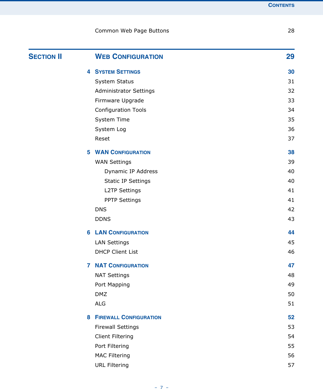
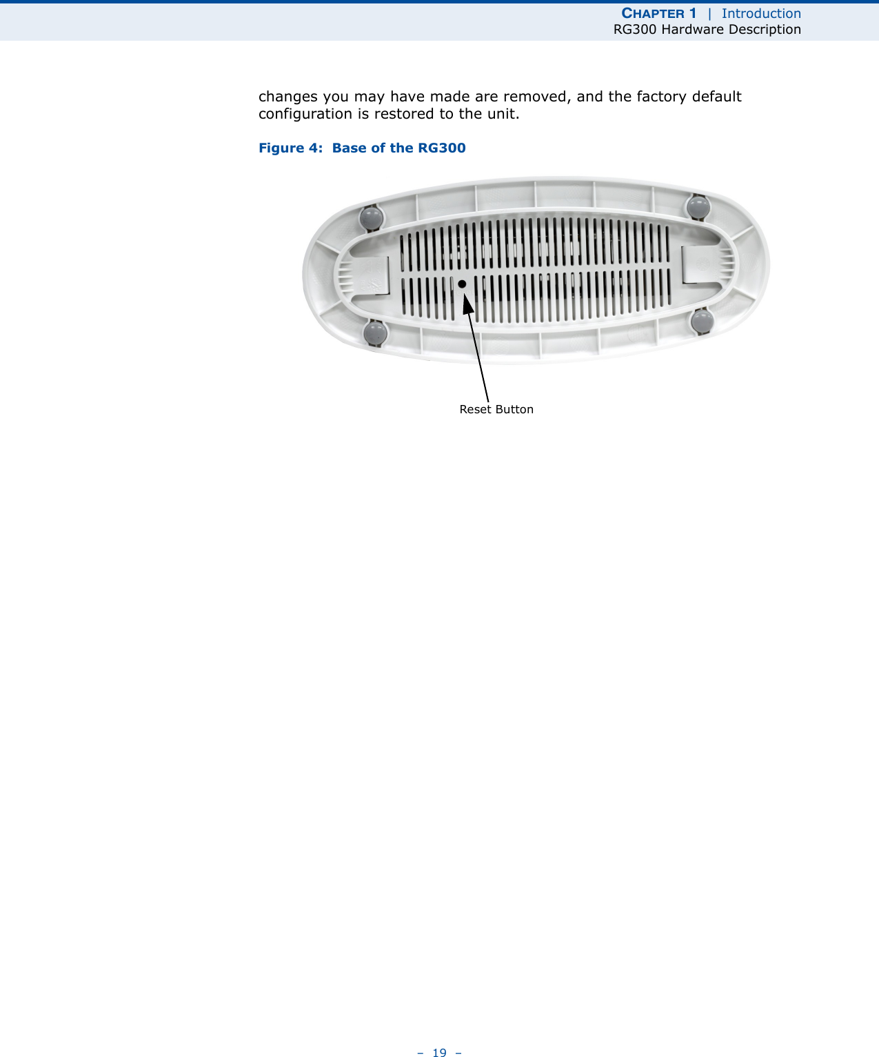
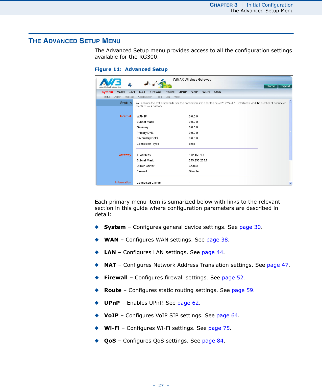
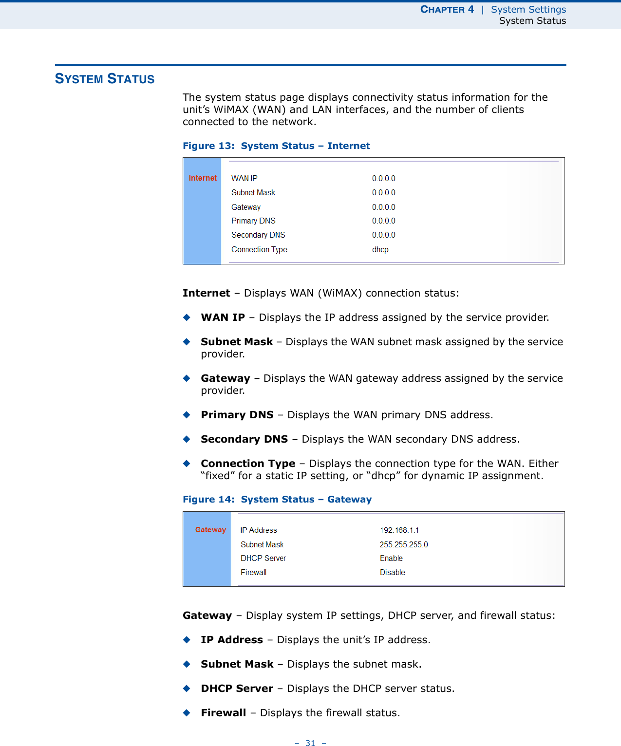
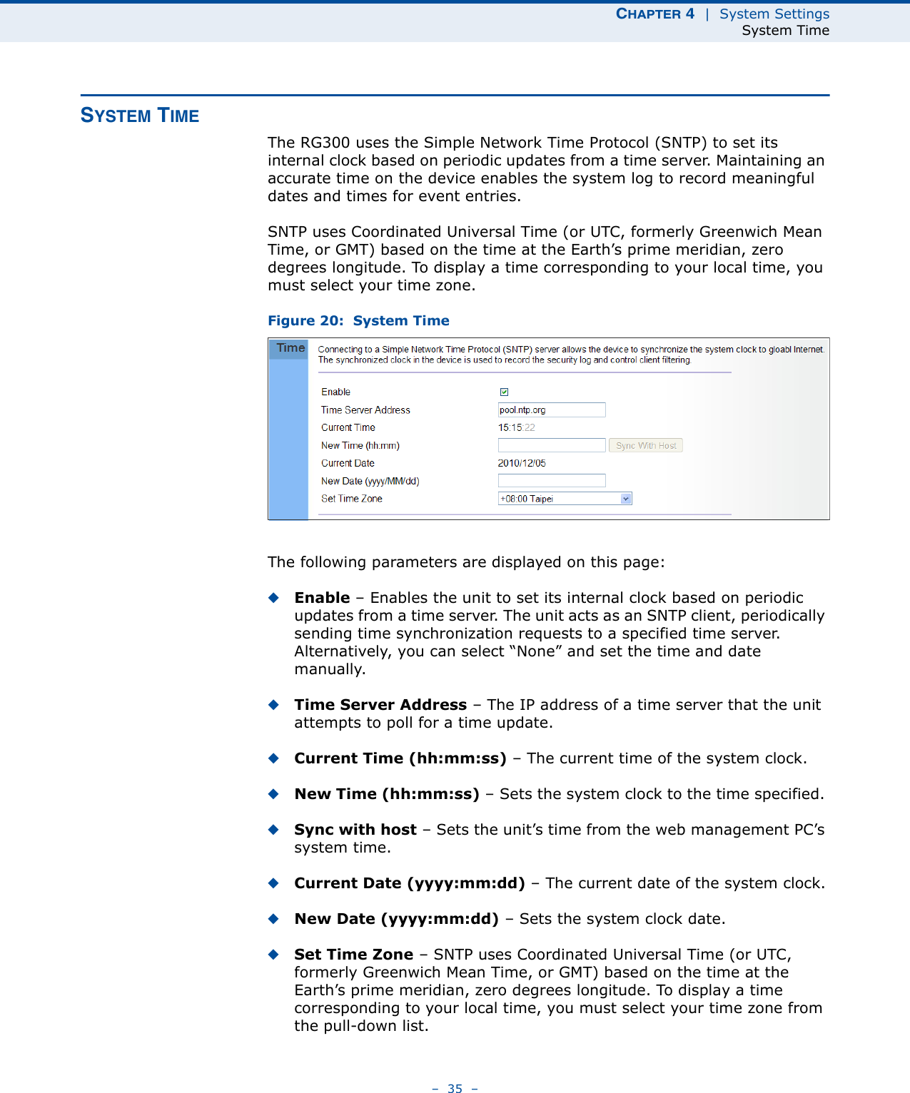
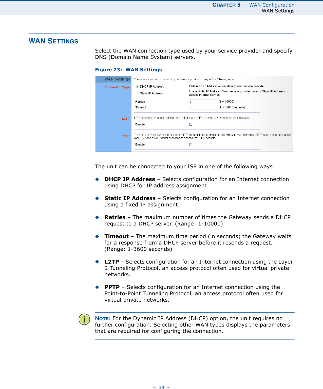
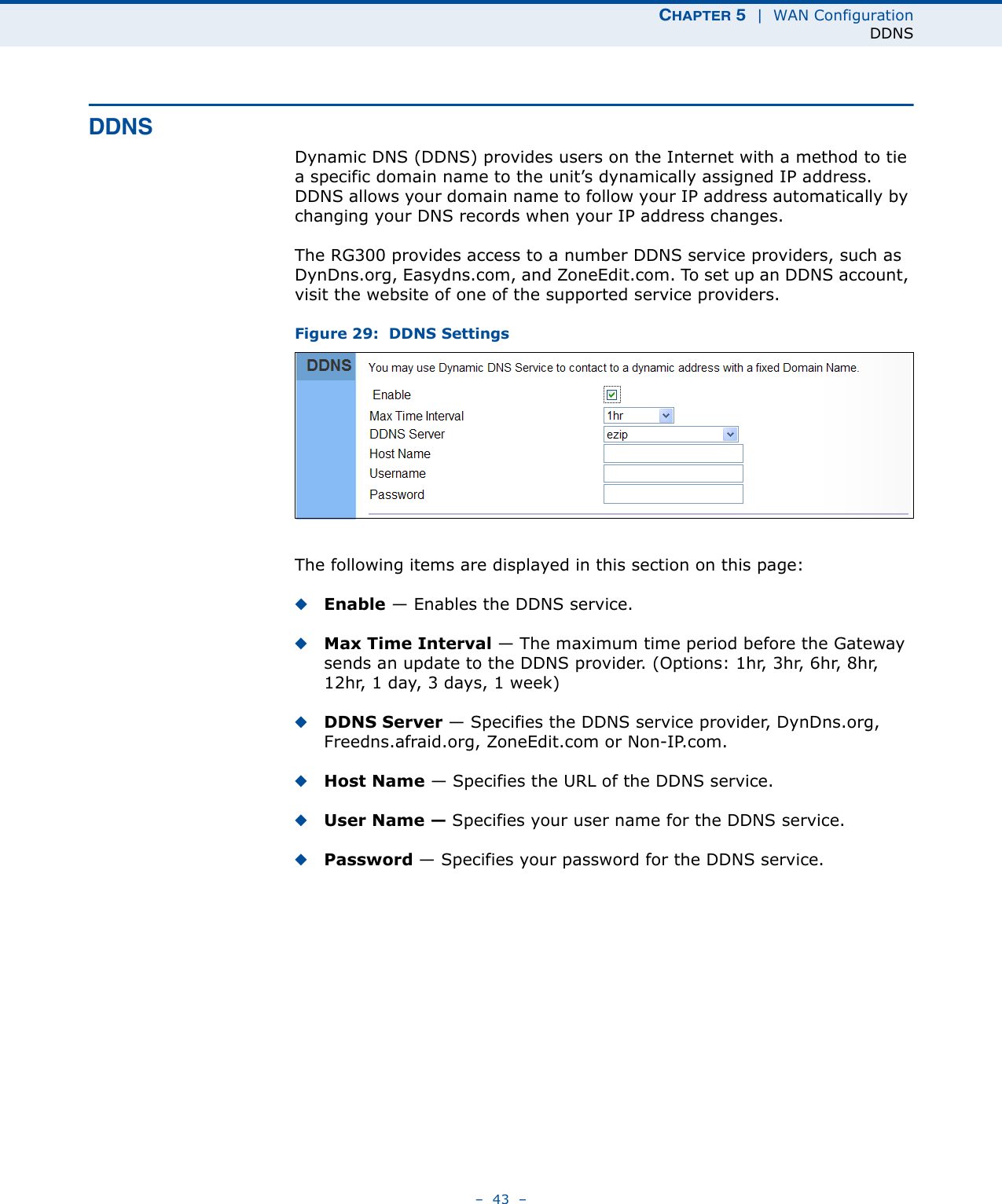

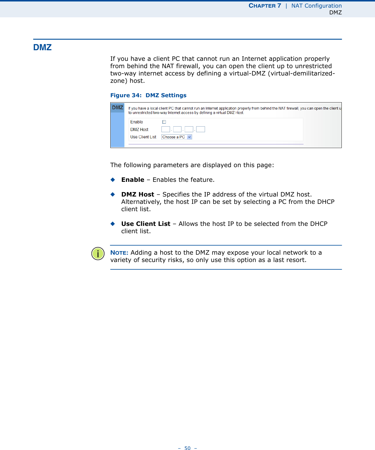
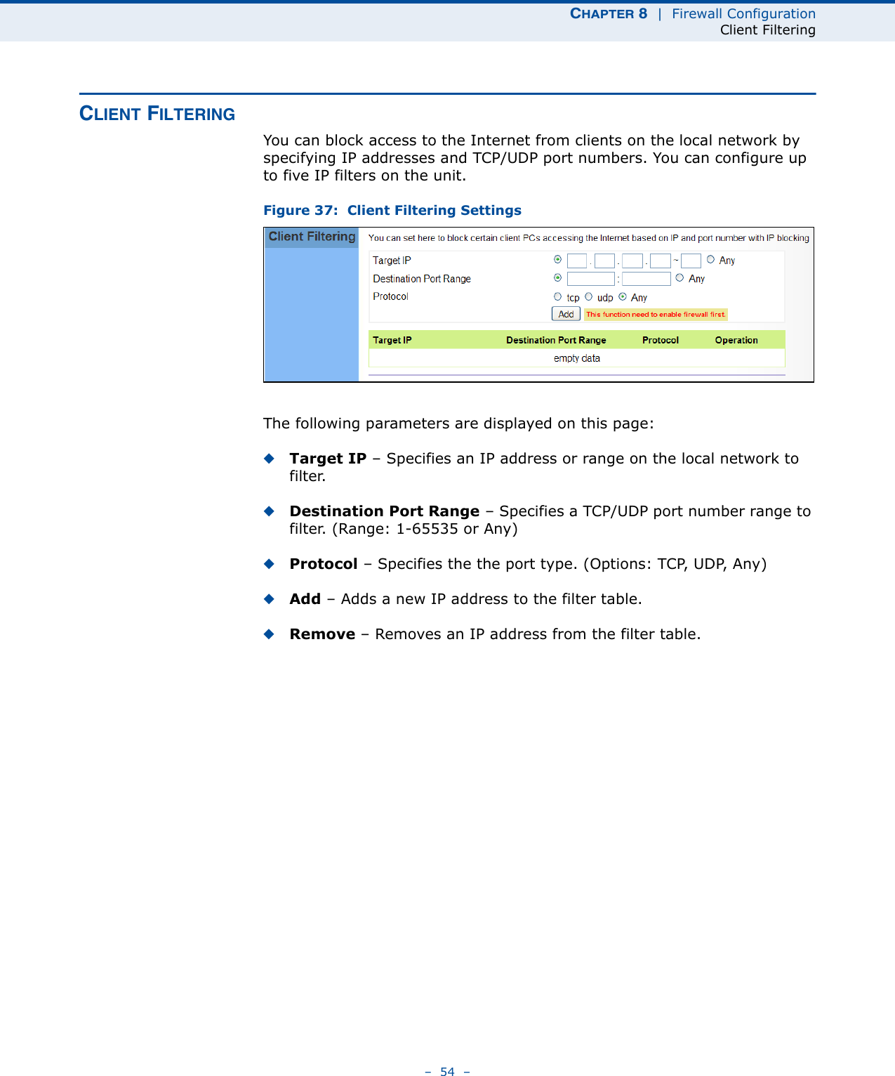
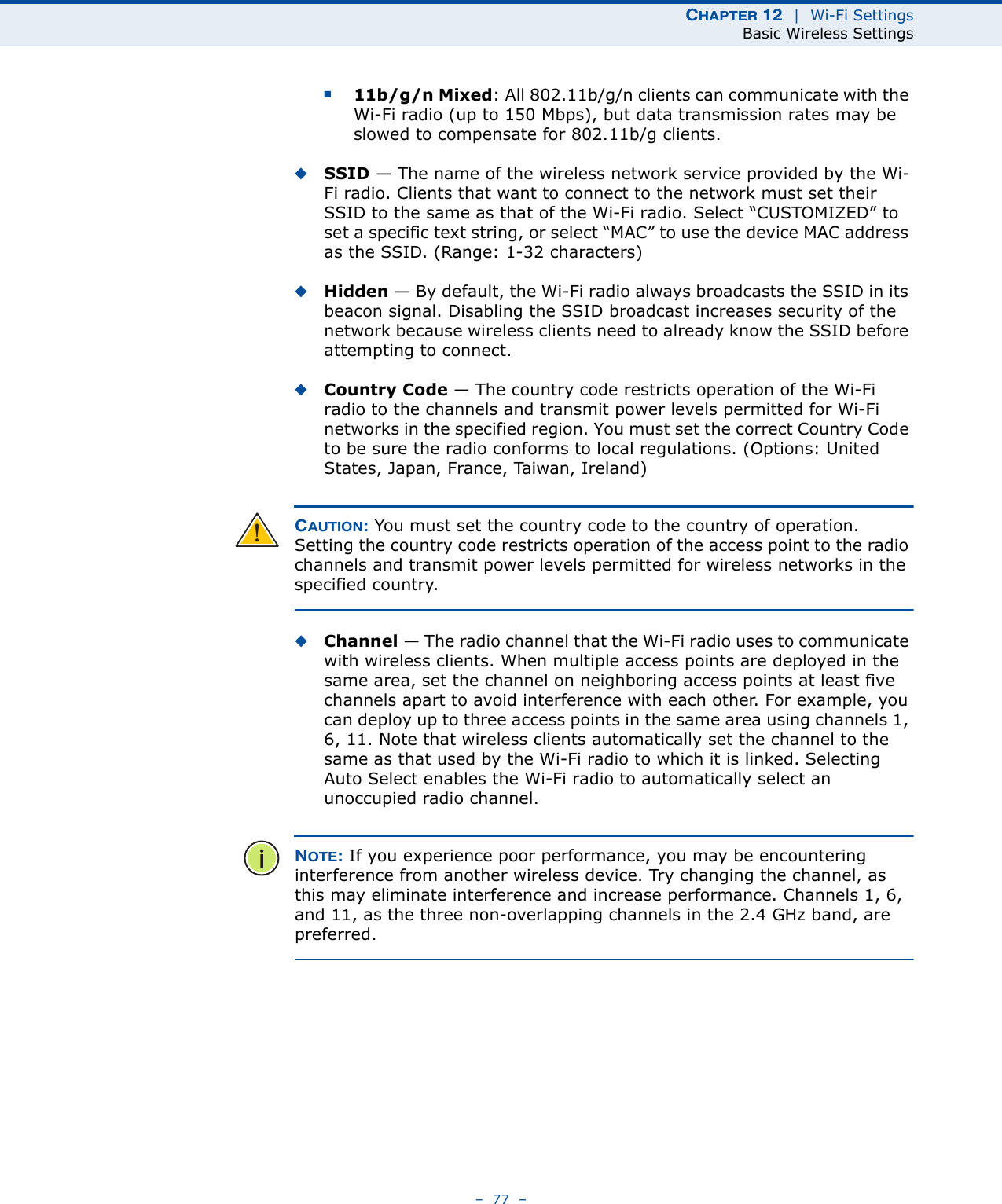
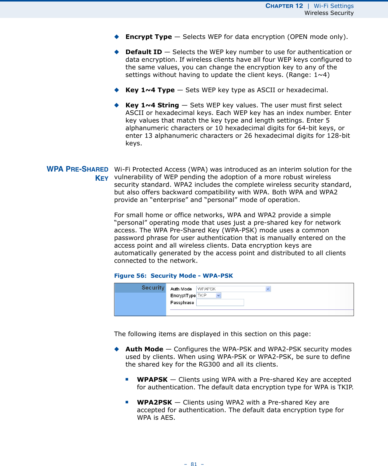
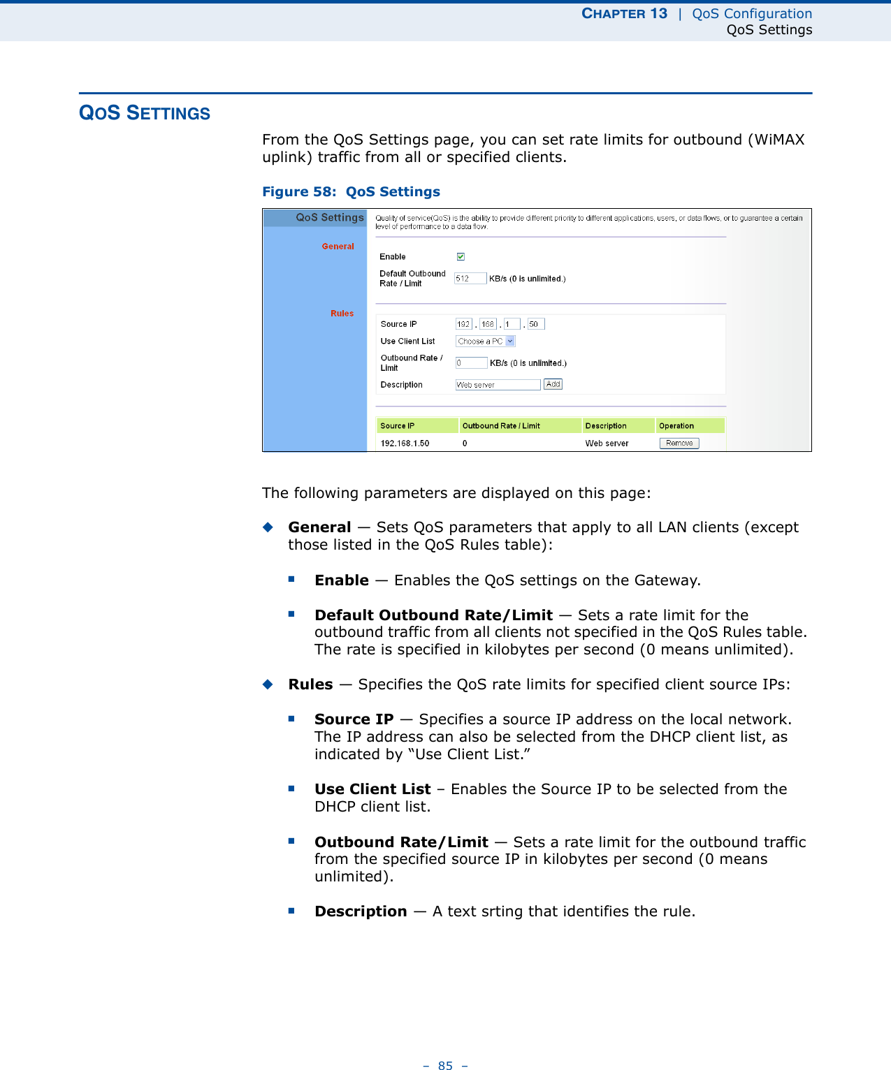
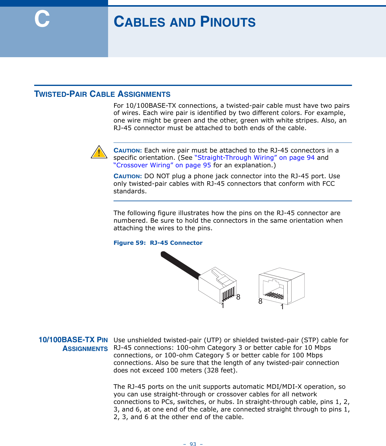
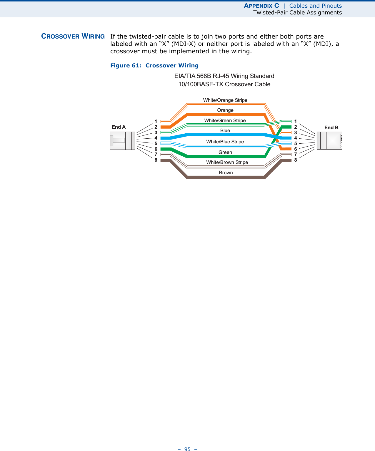
![CHAPTER 8 | Firewall ConfigurationURL Filtering– 57 –URL FILTERINGThe RG300 provides a method for blocking Internet access based on Uniform Resource Locator (URL) keywords. By filtering URLs accessed from the network, users can be prevented from reaching prohibited online content.Figure 40: URL FilteringThe following items are displayed on this page:◆String — Specifies text keyword contained in URLs that will be filtered. (Maximum 256 characters; invalid characters [‘ “ & ' # \].)◆Add — Adds a keyword string to the URL filter. ◆Remove – Removes an entry from the filter table.](https://usermanual.wiki/Accton-Wireless-Broand/FW181RG30000W/User-Guide-1456345-Page-62.png)
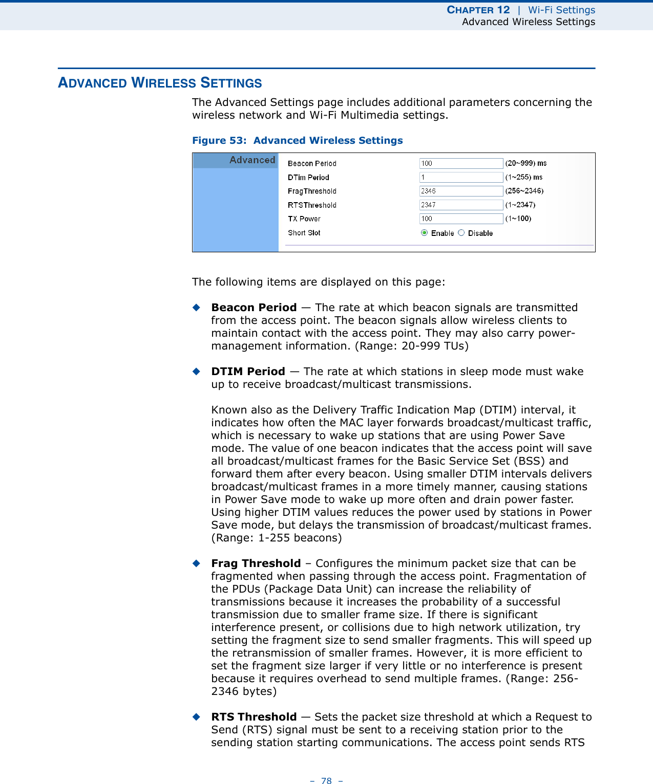
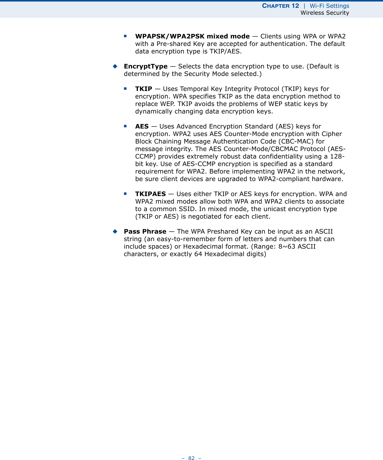
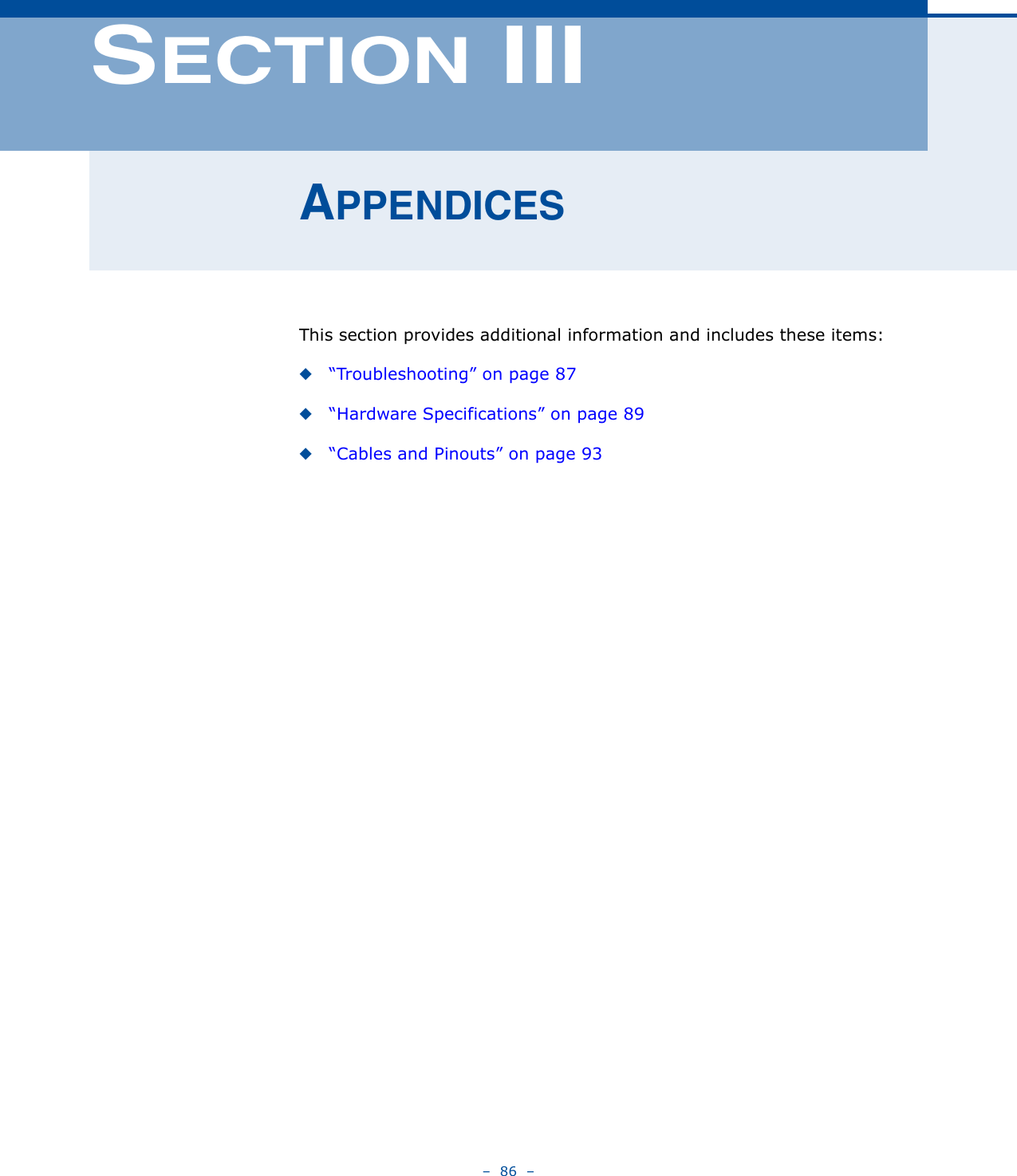
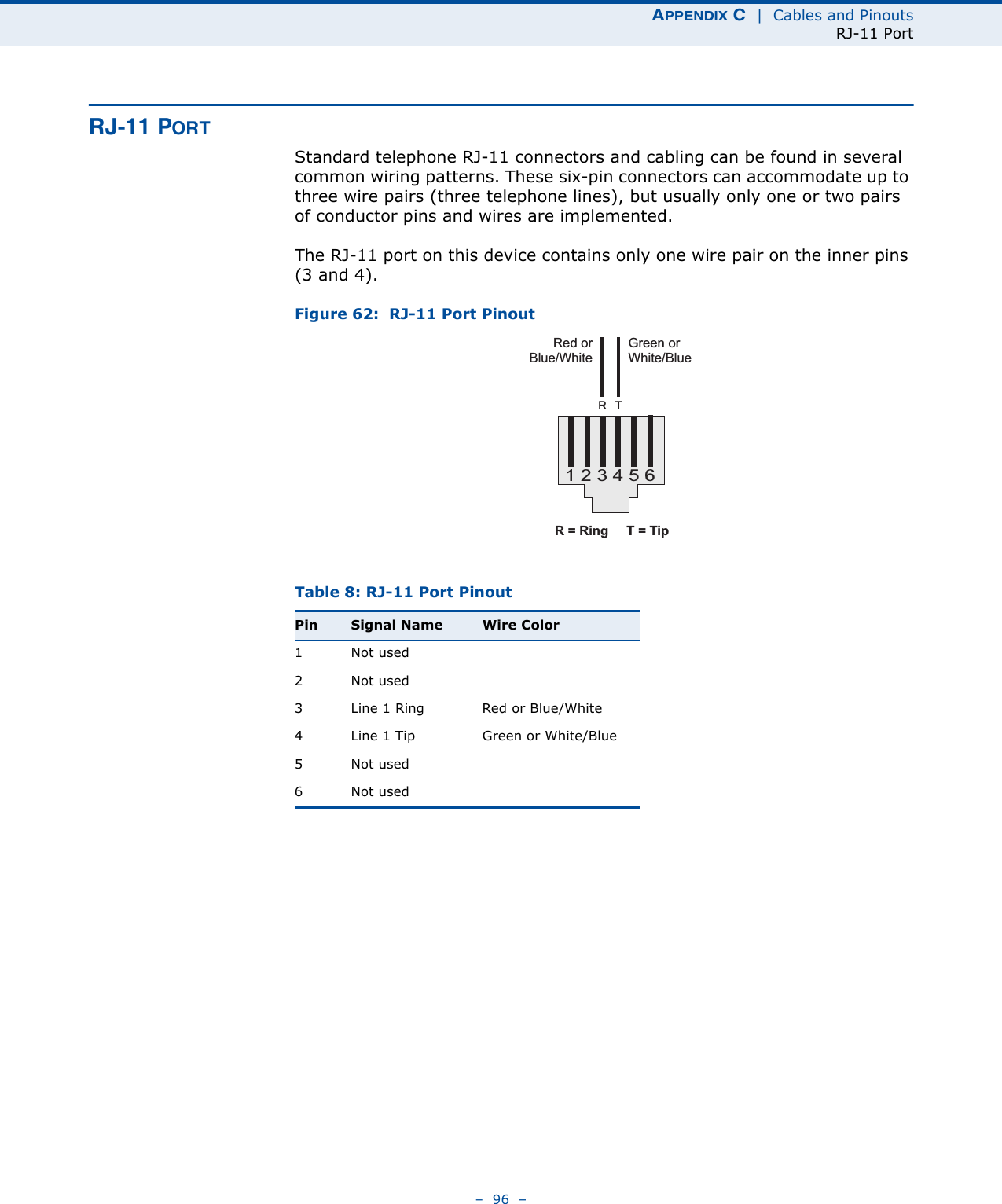
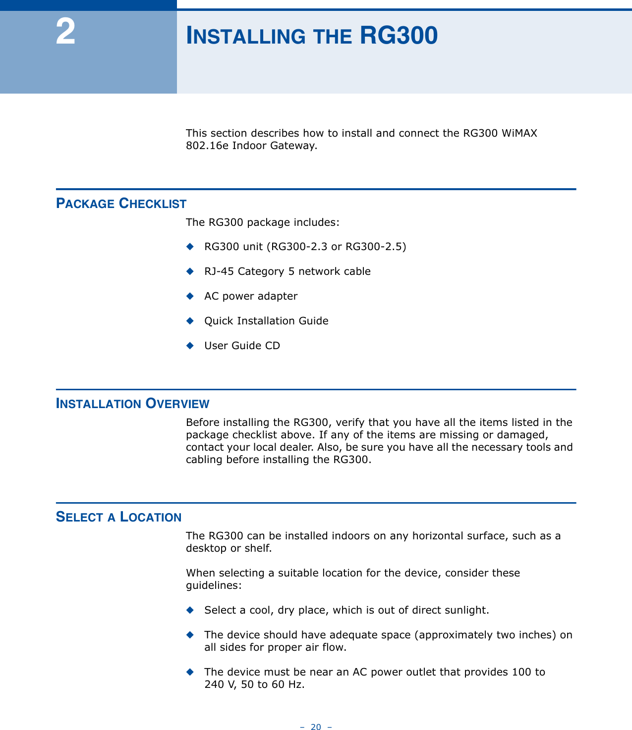
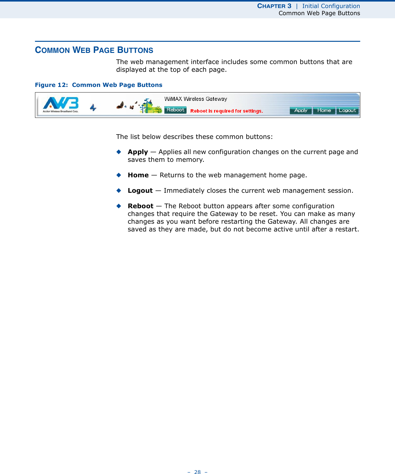
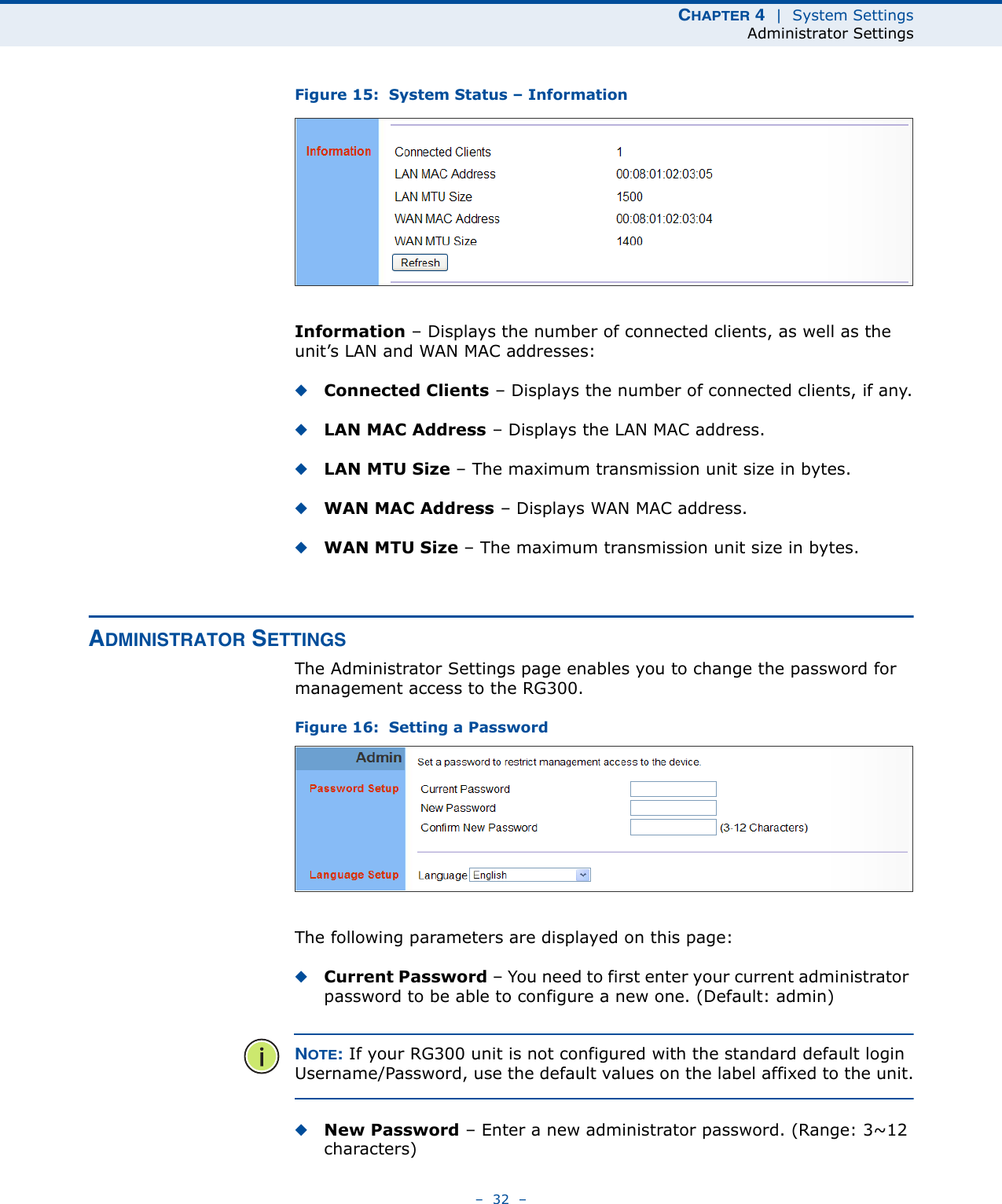
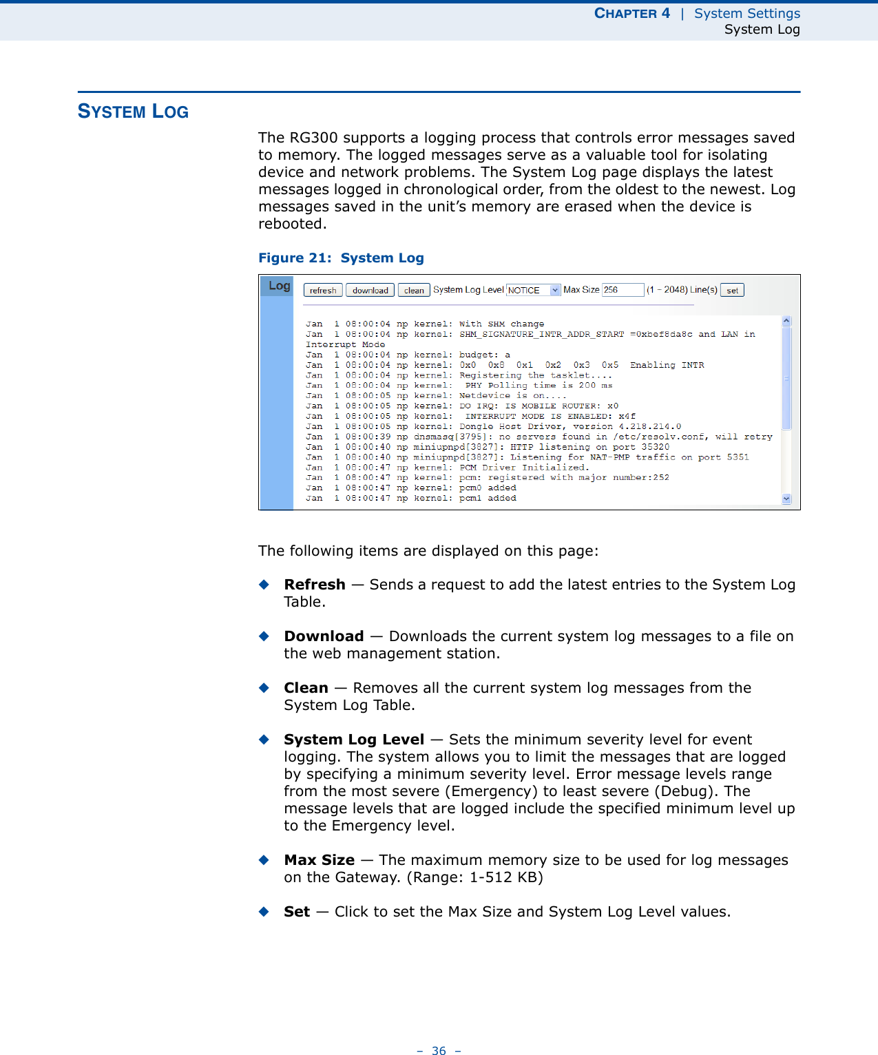
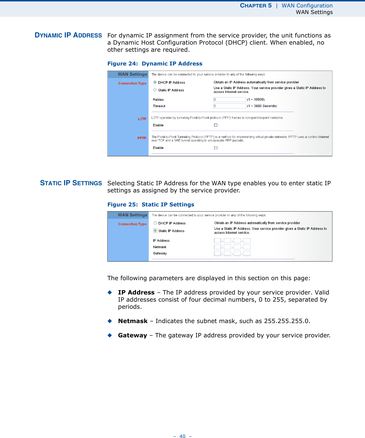
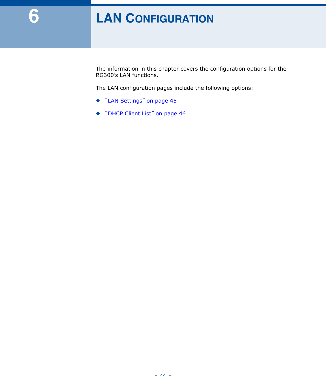
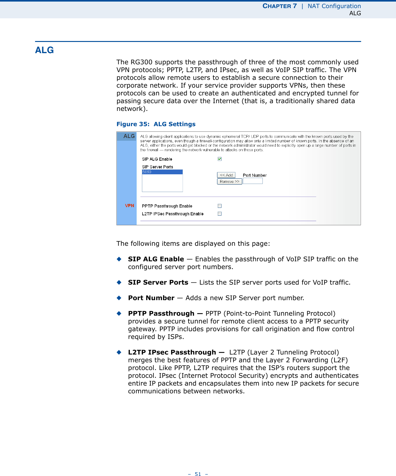
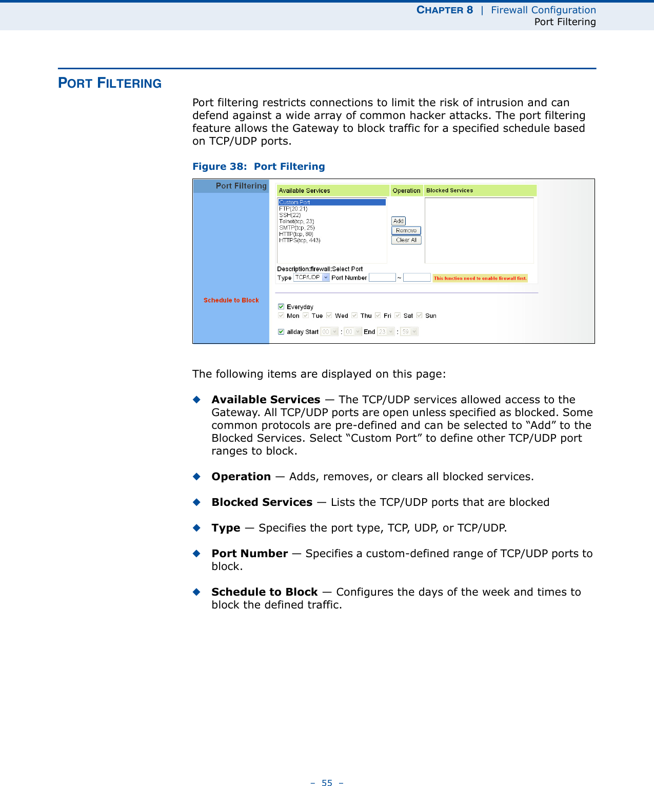
![CHAPTER 8 | Firewall ConfigurationHost Filtering– 58 –HOST FILTERINGThe RG300 provides a method for blocking Internet access based on web domains. A domain name is the name of a particular web site. For example, www.fungames.com. Figure 41: Host FilteringThe following items are displayed on this page:◆Host String — Displays current Host filter. (Maximum 256 characters; invalid characters [‘ “ & ' # \].)◆Add — Enters a domain name keyword for a host filtering. For example, myhost.example.com.◆Remove — Removes an entry from the filter table.](https://usermanual.wiki/Accton-Wireless-Broand/FW181RG30000W/User-Guide-1456345-Page-63.png)
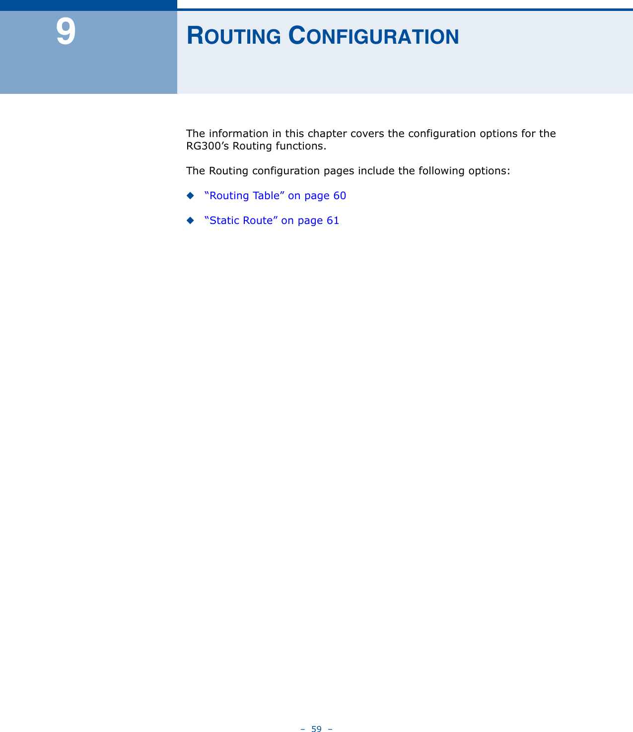
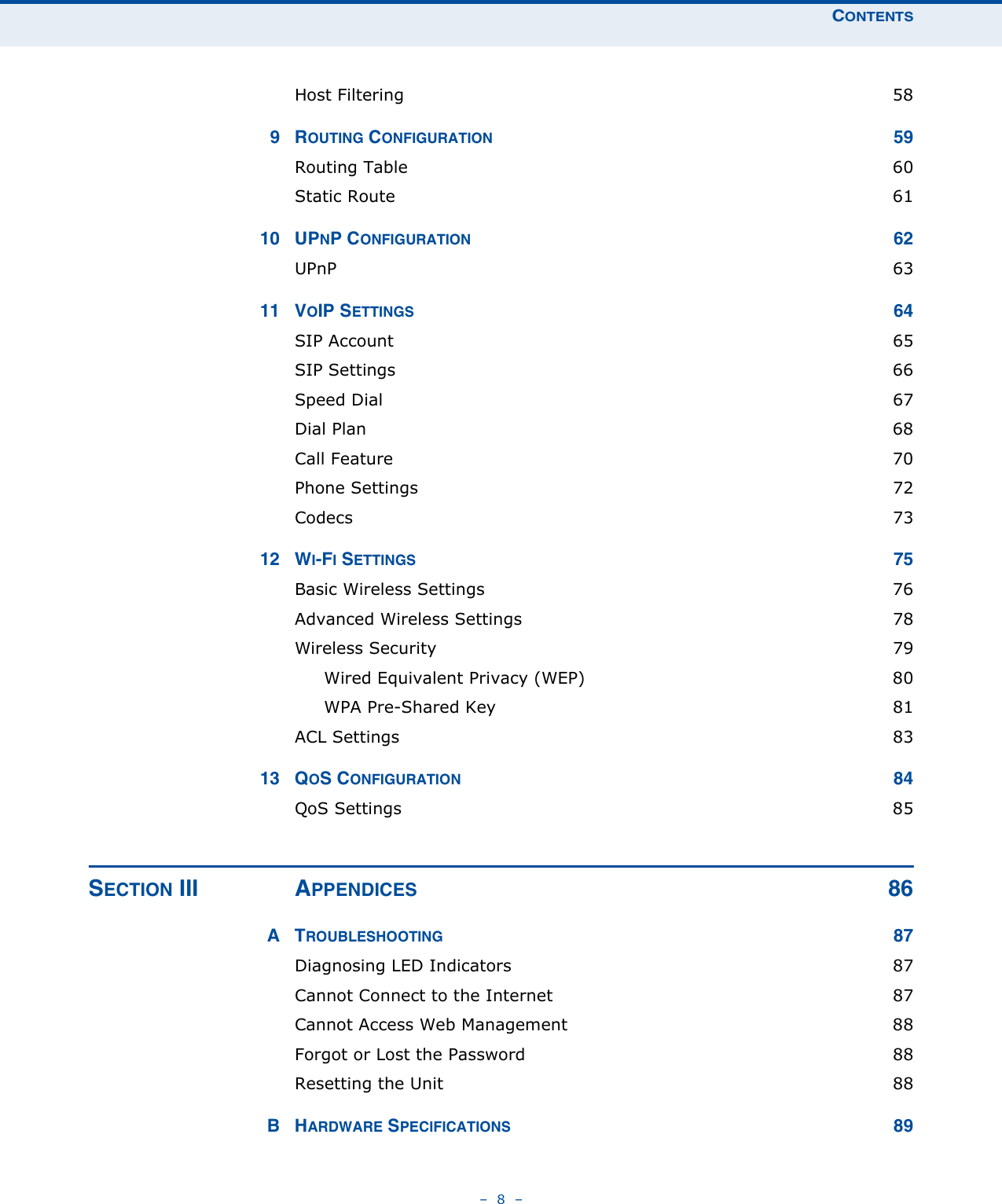
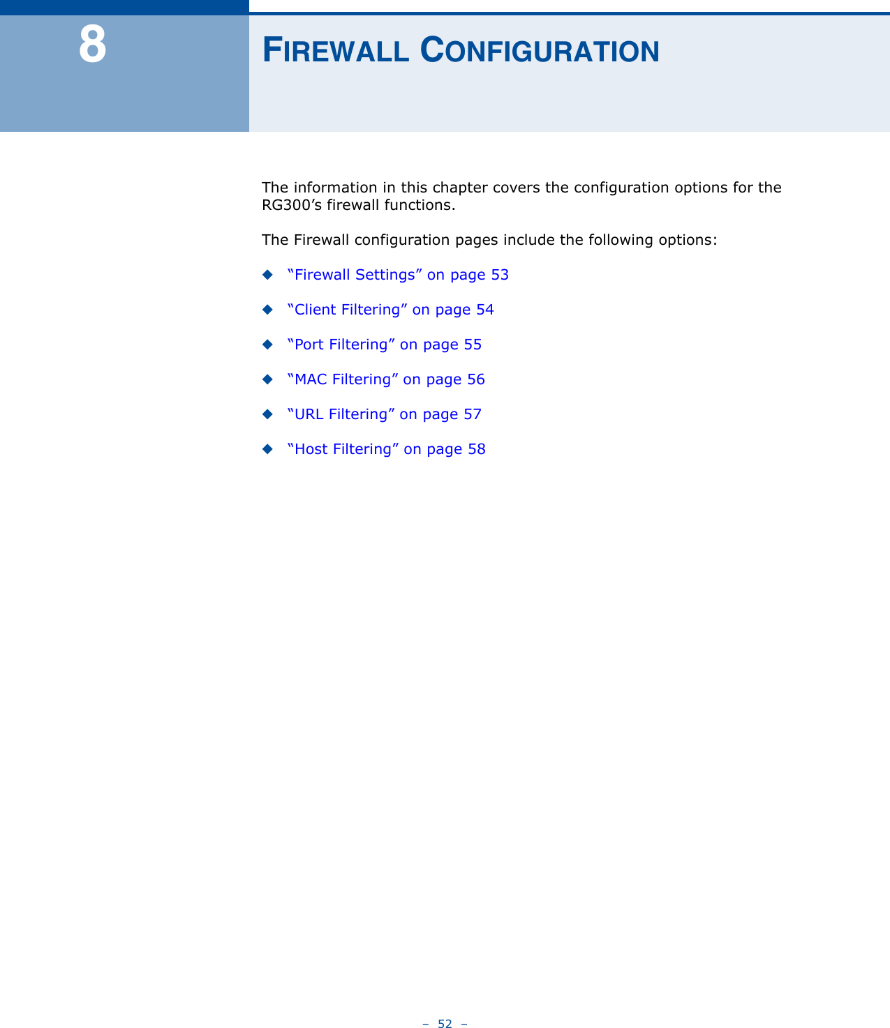
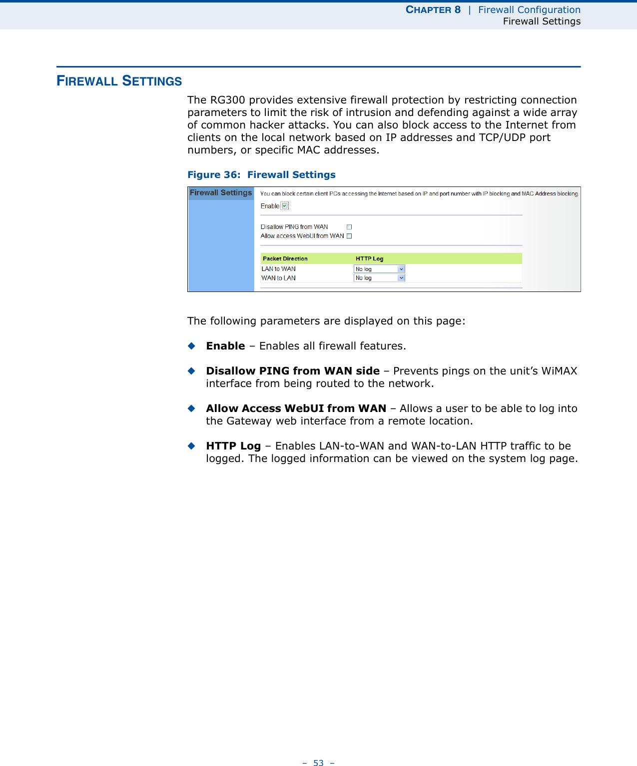
![CHAPTER 11 | VoIP SettingsDial Plan– 68 –DIAL PLANDial-plan strings specify key sequences used for specific calling features (Transfer, New Call, 3-way conference), as well as defining call restriction filters.A dial plan can filter the number and pattern of digits that a user dials to reach a particular telephone number. Access codes, area codes, specialized codes, and combinations of the number of digits dialed can all be part of a dial plan. This enables a user to predefine dialling sequences that are permitted. The dial-plan string consists of a single digit rule. A typical example of a dial-plan string is: [0123]xxxxxx.tFive standard dial plans are defined; Call Transfer Key, New Call Key, Set Speed Dial Key, Speed Dial Key, and 3-way Conference. Up to 10 other dial plans can be defined by the user.Figure 48: Dial Plan SettingsThe function of elements allowed in a dial plan are described in the table below:Table 5: Dial Plan ElementsElement Example Descriptionx xxxx Represents a digit of any value ( 0 to 9) that can be dialed on a phone. This example has a rule with four digits of any number.. xx. Indicates zero or more occurrences of the previous symbol. The example acts like a wildcard, meaning any dialed phone number of two or more digits is allowed.0-9 01xx Indicates dialed digits that must be matched. This example only allows four-digit numbers starting “01.”](https://usermanual.wiki/Accton-Wireless-Broand/FW181RG30000W/User-Guide-1456345-Page-73.png)
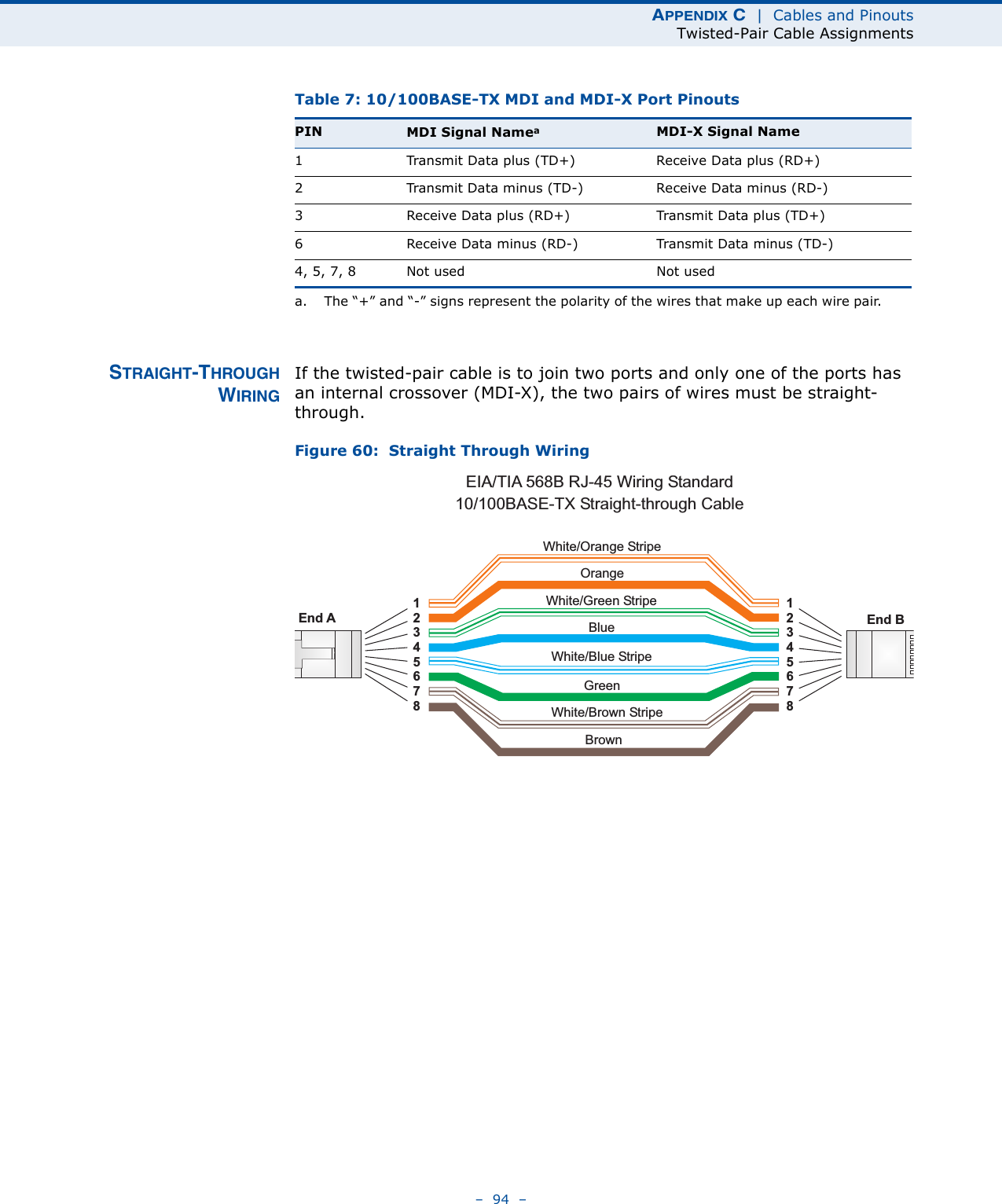
![CHAPTER 11 | VoIP SettingsDial Plan– 69 –When a user dials a series of digits, the dial-plan rule is tested for a possible match. If a match is made, the dialed sequence is transmitted. If no match is made, the dialed number is blocked and the user will hear an error tone.A dial-plan string cannot include spaces between elements. Dialed sequences that are longer than specified in a dial-plan rule are truncated after the number of specified digits. For example, if the dial-plan rule is “011x” and “0115678” is dialed, only the digit sequence “0115” is transmitted. [ ] [125-8] Limits a dialed digit to specified values or a range of values. The example specifies that only digits 1, 2, 5, 6, 7, and 8 are permitted.t xx.t The timeout indicator that can placed after dialed digits or at the end of the dial-plan string.Table 5: Dial Plan ElementsElement Example Description](https://usermanual.wiki/Accton-Wireless-Broand/FW181RG30000W/User-Guide-1456345-Page-74.png)