Accurate Technology GPDS Transmitter User Manual PROSCALE Manual Rev E
Accurate Technology, Inc. Transmitter PROSCALE Manual Rev E
UserManual.wiki
>
Accurate Technology
>
GPDS User Manual
>
Users Manual Part 6
Contents
1.
Users Manual
2.
Users Manual Part 2
3.
Users Manual Part 3
4.
Users Manual Part 4
5.
Users Manual Part 5
6.
Users Manual Part 6
7.
Users Manual Part 7
8.
Users Manual Part 8
9.
Users Manual Part 9
Users Manual Part 6
Navigation menu
Upload a User Manual
Namespaces
Wiki Guide
HTML
PDF
Info
Views
User Manual
Discussion / Help
Navigation
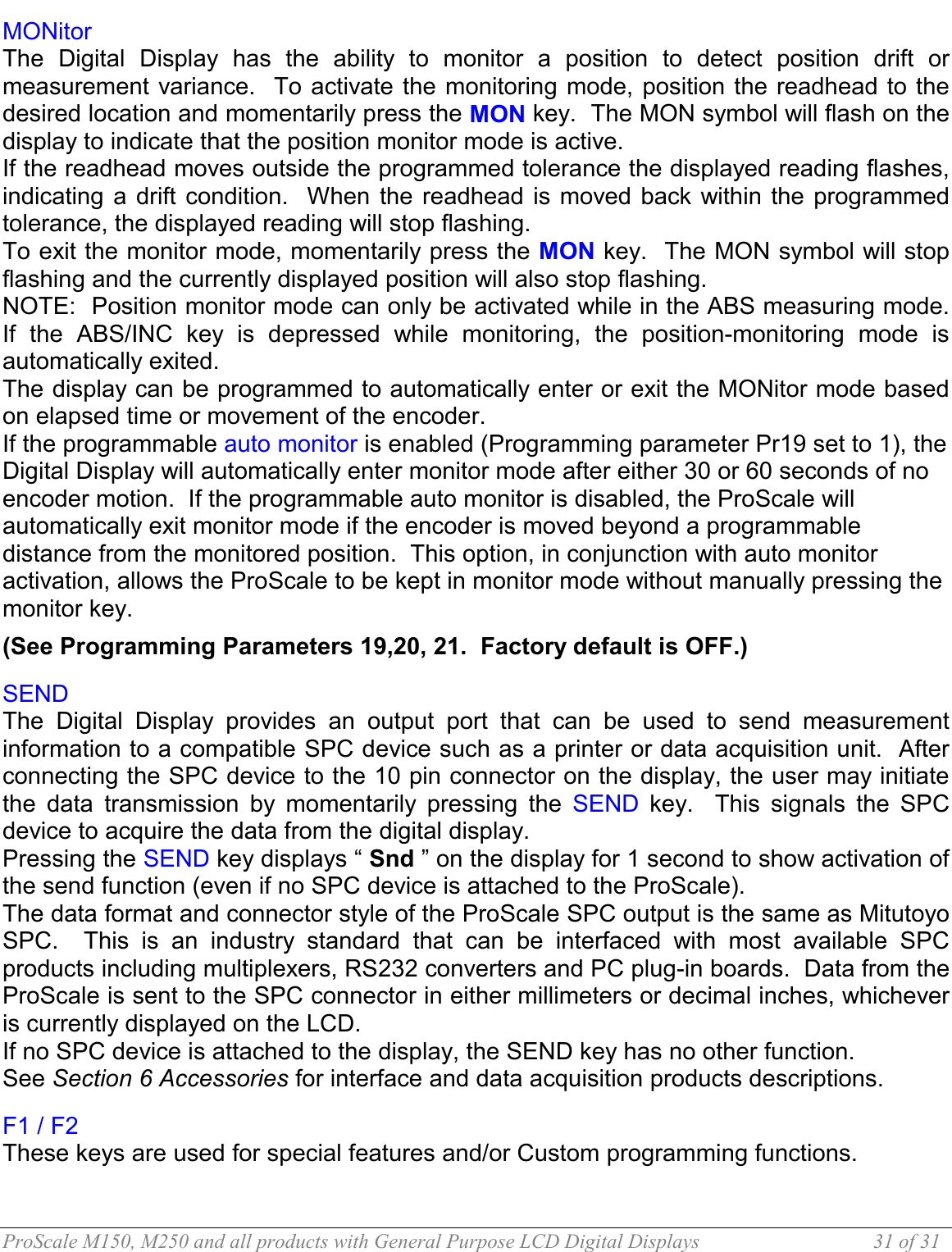
![ProScale M150, M250 and all products with General Purpose LCD Digital Displays 33 of 33 Programming Parameters are listed below. Values in [ ] are the available range of values that can be programmed for that entry. Factory defaults are shown in bold. Pr0 – Encoder Direction [0,1] Change value to reverse the direction of measurement readings. Pr1 – Enable/Disable Segment Offset [0, 1] 0 = For ABSOLUTE scales shorter than 430mm, (16.9in). ALL Incremental scales 1 = For All ABSOLUTE scales longer than 430mm, (16.9in). Pr2 – High Speed Readhead [0, 1] 0 = Normal Readhead 1 = High Speed Readhead Use this setting only if instructed by special instructions included with High Speed Readheads. A setting of 1 will impact battery life. Pr3 – Enable/Disable the +, - and ZERO keys [0,1] 0 = Disables operation of Zero, + and – keys (Display will be in Lock Mode). 1 = Enables operation of Zero, + and – keys. Pr4 – Display Resolution [0, 1, or 2] Sets the displayed resolution in decimal mode. (No change in fractions mode.) 0 = Reduced resolution Inch = xxx.xx MM = xx.x 1 = Normal resolution Inch = xxx.xxx MM = xx.xx 2 = Increased resolution Inch = xx.xxxx MM = xx.xx (Inch mode only) Auto scaling will allow measurements of over 100 inches when in high resolution. Measurements over 100 inches will automatically be reduced to 3 decimal places. Pr5 – Metric Display Units [0, 1] Controls whether the measured value is displayed in millimeters or centimeters when in metric mode. 0 = millimeters 1 = centimeters Pr6 – Disable Fractions/Inches [0, 1, 2] 0 = All measurement modes (millimeters or centimeters, inches and fractions) 1 = No Fractions. Only decimal inches and metric units* will be displayed. 2 = Only Metric. No Imperial (decimal inches or fractions) will be displayed. * Pr5 will determine if mm or cm are displayed for metric units. Pr7 – Scaling Factor [.001 .. 99.999] Default = 1.000 (No Scaling.) The multiplier applied to the measurement. Scaling factors less than 1.000 will make the displayed measurement less that the actual measurement. Scaling factors greater than 1.000 will make the displayed measurement greater than the actual measurement.](https://usermanual.wiki/Accurate-Technology/GPDS.Users-Manual-Part-6/User-Guide-488180-Page-3.png)
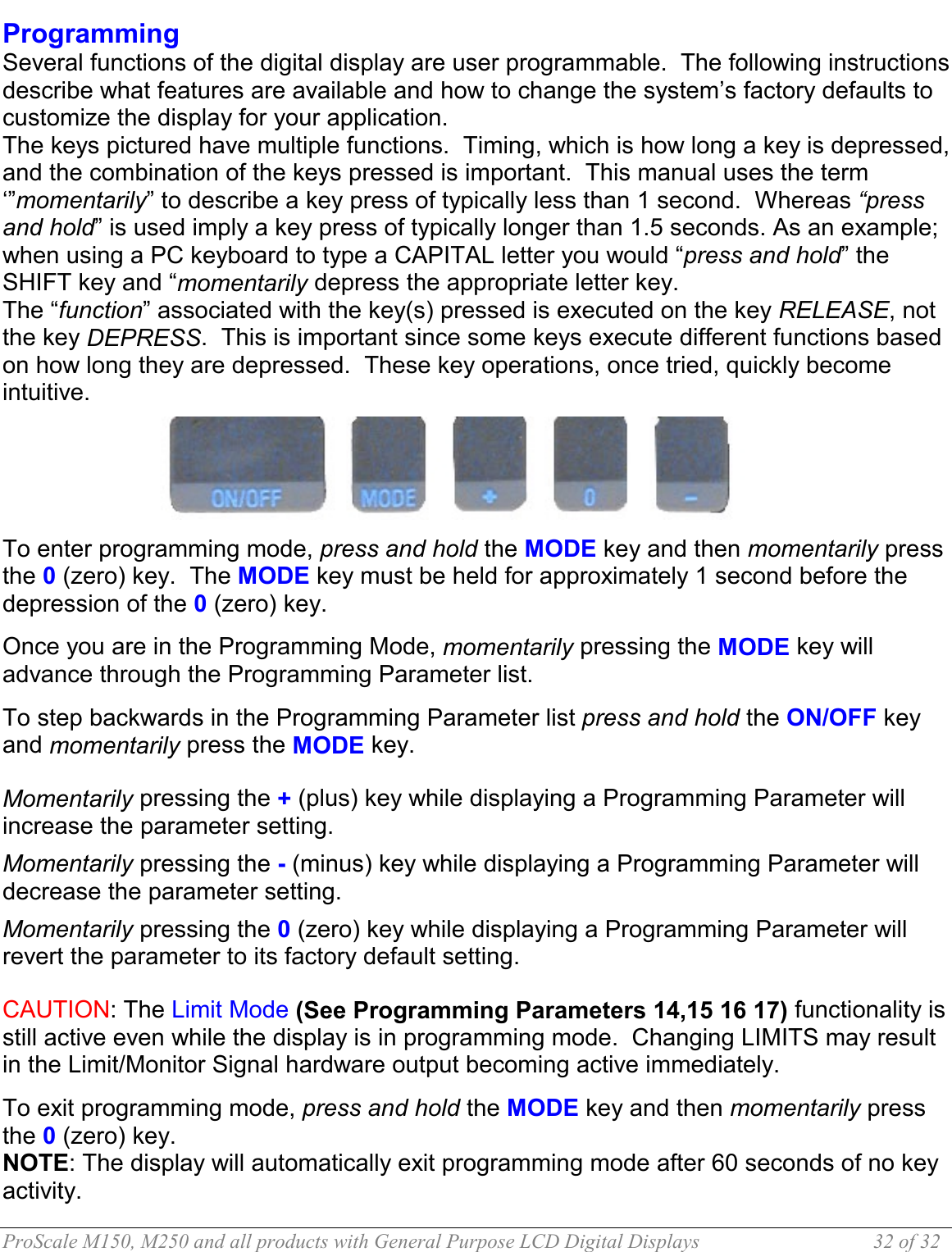
![ProScale M150, M250 and all products with General Purpose LCD Digital Displays 34 of 34 Pr8 – Automatic Power Off [0 to 60] Default = 15. Sets the amount of time in ‘minutes without activity’ before the display automatically turns off. 0 = Disables Auto Off. Encoder motion or ON/OFF key “wake-ups” the display and resets the timer. Pr9 – Auxiliary Keys Enable/Disable [0..7] 0 = ABS/INC, MON and HOLD Disabled 1 = ABS/INC Key Enabled 2 = MON Key Enabled 4 = HOLD Key Enabled 7 = All Keys Enabled To enable keys, add up combination of key values. A value of 2 enables only the MON key. A value of 7 enables all 3 Keys. Pr10 – Offset Addition Enable [0, 1] 0 = Offset Addition Disabled 1 = Offset Addition Enabled. SEE ALSO Pr11, Pr12, Pr13 Pr11 – Offset Addition 1 [-999.999 to 999.999in] or [-9999.99 to 9999.99mm] When offset 1 is selected (see section 4 -Offset Addition), this value is added to the current ABS position. Default = 1.000IN Only active if Pr10 is set to 1. Note: Default is set in Inches Pr12 – Offset Addition 2 [-999.999 to 999.999in] or [-9999.99 to 9999.99mm] When offset 2 is selected (see section 4 -Offset Addition), this value is added to the current ABS position. Default: 1.500IN Only active if Pr10 is set to 1. Note: Default is set in Inches Pr13 – Offset Addition 3 [-999.999 to 999.999in] or [-9999.99 to 9999.99mm] When offset 3 is selected (see section 4 -Offset Addition), this value is added to the current ABS position and displayed. Default: 2.000IN Only active if Pr10 is set to 1. Note: Default is set in Inches Pr14 – Output Signal Mode [0, 1] Configures the hardware output signal for activation on MONitor drift conditions or Upper/Lower limit alarm conditions. (24VDC displays only) 0 = Monitor drift, 1 = Limit.Alarm SEE ALSO Pr15, Pr16, Pr17](https://usermanual.wiki/Accurate-Technology/GPDS.Users-Manual-Part-6/User-Guide-488180-Page-4.png)
![ProScale M150, M250 and all products with General Purpose LCD Digital Displays 35 of 35 Pr15 – Output Polarity [0, 1]. Used to configure the signal output. N/O or N/C in relation to circuit ground. 0 = N/O, the output is Normally Open (not conducting to ground). 1 = N/C, the output is Normally Closed (conducting to ground). Pr16 – Lower Limit [-999.999 to 999.999in] or [-9999.99 to 9999.99mm] Sets the lower limit alarm value. Default = 0.000IN. Active only when parameter Pr14 = 1. Note: Default is set in Inches Pr17 – Upper Limit [-999.999 to 999.999in] or [-9999.99 to 9999.99mm] Sets the upper limit alarm value. Default = 5.000IN. Active only when parameter Pr14 = 1. Note: Default is set in Inches Pr18 – Drift Tolerance [.01 to 9999.99mm ] or [.001 to 999.999in]. Range of motion allowed (+ or -) while in MONitor mode. Default =. 01IN. Note: Default is set in Inches Pr19 – Automatic Monitor ON Time [0, 1 or 2] Configures display to automatically activate MONitor mode after 30 or 60 seconds of encoder inactivity. 0 = disabled. 1 = 30 seconds. 2 = 60 seconds. Pr20 – Automatic Monitor OFF Enable [0, 1] Configures display to automatically exit MONitor mode after a programmed distance (Pr21) has been exceeded from the drift tolerance position (Pr18). 0 = disabled 1 = enabled. Pr21 – Automatic Monitor OFF Distance [0.001 to 999.999in] or [0.01 to 9999.99mm]. The distance that must be exceeded from the drift tolerance position (Pr18) to activate auto monitor off. Default = 0.500in This parameter is relevant only when Pr20=1. Note: Default set in Inches Pr22 – Backlight ON time [0, 1, 2, 3 or 4] The ON time of the LCD backlighting (24VDC displays only). 0 = always off. 1 = 3 seconds. 2 = 7 seconds. 3 = 15 seconds. 4 = always on. Backlighting is activated when a key is pressed. Pr23 – Future Enhancement DO NOT CHANGE [0,1,2] Default =1 Pr24 – Future Enhancement DO NOT CHANGE [0..63] Default =0 Pr25 – Future Enhancement DO NOT CHANGE [0..31] Default =0 CAUTION: Pressing and holding the ON/OFF and MODE key for 10 seconds while the display is turned off will perform a full segment LCD test AND re-set all programming parameters to factory defaults](https://usermanual.wiki/Accurate-Technology/GPDS.Users-Manual-Part-6/User-Guide-488180-Page-5.png)