Ace Antenna USHR-1900 PCS Amplifier User Manual 304385
Ace Antenna Company, Inc PCS Amplifier 304385
users manual

ACE Antenna
USHR-1900
Bi-Directional Amplifier (BDA)
Installation and Operations Manual
10/2002
ACE ANTENNA
ACE Antenna
9201 IRVINE BLVD
IRVINE, California
Tel: (949) 916-6244
Fax(949) 916-5264
Email: aceusa@aceteq.com
Web: www.aceteq.com

ACE Antenna
2
Table of Contents
1. General Information
1.1 Introduction
1.2 Specifications
1.3 Description
2 Installation
2.1 Introduction
2.2 Unpacking and Inspection
2.3 Preparation for Use
2.4 Before Installation
2.5 Antenna Installation
2.6 BDA Installation
2.7 Connectors
2.8 Installation Example
3 Operation
3.1 Introduction
3.2 Operating Instructions
4 Trouble Shooting
5 Drawings
ACE Antenna
3
1. General Information
1.1 Introduction
This manual provides information pertaining to the installation and operation of
ACE Antenna’s USHR-1900 “Ultra Slim Home” BDAs. This unit is for CDMA,
GSM, and TDMA modulations in the PCS frequencies as shown in Table 1-1.
<Table 1-1: USHR-1900 BDA >
Model Number Down Link*
Frequencies
Up Link**
Frequencies Modulation
USHR-1900
1930 ~ 1990MHz 1850 ~ 1910 MHz CDMA,GSM,TDMA
*: Down Link (= Forward Path) is from base station to mobile
**: Up Link ( = Reverse Path) is from mobile to base station
Professional Installation Only
To ensure compliance with FCC rules and regulations, USHR-1900 must
be installed by trained technicians. The unit may not function properly if
not installed correctly.

ACE Antenna
4
1.2 Specifications
<Table 1-2: USHR-1900 Specifications>
PARAMETER SPECIFICATION
Down Link 1930 ~ 1990 MHz
Frequency
Up Link 1850 ~ 1910 MHz
Output Power + 7 dBm (5 mW )
Input Power - 43 dBm max
Linear Gain 50 dB
Gain Flatness 7 dB max
1 dB Compression + 14 dBm
3rd Order Intercept + 24 dBm
Reverse Shutdown +10 dBm (±1dB)
Noise Figure 8 dB max
Propagation Delay 1 µs max
VSWR 2 :1 max
Impedance 50 Ω
Status LED POWER: GREEN
FAIL: RED
Power Consumption 5.2 V / 500 mA
Input Voltage AC/DC Adaptor, DC 5.2 V / 1A, 5.2 W
RF Connectors Type SMA Female
Operating -20 °C to 50 °C
Temperature
Storage -30 °C to 60 °C
Dimensions (W x H x D , inch) 3.10” x 3.80” x 1.54”
Weight (Pound) 1.1 lb

ACE Antenna
5
1.3 Description
This product is designed for offices, hotel rooms, small parking lots, garages or
small buildings, helping to improve PCS communications signal and coverage by
extending the coverage of a base station.
Outdoor antenna receives from a PCS base station, then USHR1900 BDA amplifies
the signal. After amplification, the signal is passed through to the indoor antennas.
Conversely, signals from handsets are amplified and retransmitted to the base
station.
2. Installation
2.1 Introduction
This section provides information for the installation and setup of the USHR-1900
BDA. The information consists of procedures for unpacking, inspection and
preparation for the installation, as well as the actual installation and the setup.
2.2 Unpacking and Inspection
Examine the shipping carton for damage before unpacking the unit. If the shipping
carton is damaged, try to have the carrier’s agent present when the equipment is
unpacked. If visual inspection reveals physical damage(s) to the equipment, you
should send it back for replacement.
Verify that the equipment is complete, as listed under packing slip. Contact ACE
Antenna with any missing component.
2.3 Preparation for Use
2.3.1 Power Requirements
The power supply of the USHR-1900 accepts 5.2 VDC. Power consumption of the
USHR-1900 is approximately 2.6 Watts.
Use Only with the Supplied AC/DC Adaptor
The USHR-1900 requires the correct power supply to operate properly.
If abnormal power is detected, the “Power Supply” LED on the front face
of the unit will turn red and the unit will stop functioning until it is reset
and connected to the correct power supply. Increasing the supply
voltage beyond what it specified will not increase the gain of the unit, but
ma
y
cause severe dama
g
es.

ACE Antenna
6
2.3.2 Operating Environment
The USHR-1900 is intended for indoor use only. Do not install it where it might be
exposed to the outside elements as this could result in destruction of the unit and
other hazards.
For normal operations, the environmental conditions should be as follow:
Temperature range: –20 °C to 50 °C, Maximum Humidity: 95 %
2.4 Before Installation
You will need to determine the following before beginning the USHR-1900
installation:
a. Base station location
b. Location where the outdoor antenna is to be installed
c. Location where the indoor antenna is to be installed
d. Location where the USHR-1900 is to be installed
e. Length and type of coaxial cable needed to connect from the outdoor antenna to
the BDA unit
f. Length and type of coaxial cable needed to connect from the BDA unit to the
indoor antenna
2.5 Antenna Installation
2.5.1 Outdoor Antenna
Select a site for your outdoor antenna, making sure you have enough signal strength
at that location. Using coax cable, connect the antenna to the BDA. If you are
using a directional antenna such as a Yagi type, the antenna should be installed so
that it is in line of sight of the base station. Then, align the directional antenna
toward that direction, and secure the antenna using provided mounting hardware.
Use of a lightning arrester is highly recommended. By installing a lightning
arrester between the outside antenna and the BDA, you can protect the BDA unit
from electrical surge from lightning.
2.5.2 Indoor Antenna
Install the indoor antenna at a convenient location. It should be free of metallic
obstruction in order to have an effective coverage. Depending on the circumstance
of the installation, either one or a combination of following antennas can be used:
Ceiling mount patch antenna, Wall mount patch antenna, Corner reflector

ACE Antenna
7
2.6 BDA Installation
USHR-1900 is an indoor BDA. Accordingly, the environment of the intended
installation site needs to be considered. The BDA must be shielded from moisture,
such as rain, and excessive temperatures. The operating temperatures should be
between -20 °C and 50 °C.
2.6.1 Turn-On Procedure
Verify all RF connectors are tightened and cables and antennas are secured.
Connect AC/DC Adaptor on the BDA’s DC IN connector. The Power indicator
LED should be green. Make sure that no other LED is illuminated. If any other
LED is lit, consult the trouble shooting page of this manual, or “2.6.2 Antenna
Isolation and Alignment” section.
2.6.2 Antenna Isolation and Alignment
USHR-1900 is equipped with an over drive protection circuit. If the output power
level of reverse path(=Up Link) exceeds prescribed limit, then reverse path is
disconnected and the FAIL LED (RED) is on. BDA automatically checks output
power level every 1 minute of a 5 minute cycle when reverse path has over power .
If reverse path still exceeds level then shut down mode continues for another 10
minutes. After 10 minutes, reverse path is switched on again and it checks output
power level again. (Repeats the process)
A. Antenna Alignment
If you are triggering the overdrive alarms at any point, try to increase the isolation
between the antennas by relocating them. The indoor antenna should be placed
physically as far away from the outdoor antenna as practical. If the geometry of the
intended coverage area allows it, you should also try the indoor antenna in such
way that interference between the antennas is at the minimum. If you are using
directional antennas, try to find a location for the indoor antenna where it can cover
the needed area and oriented back to back with respect to the outdoor antenna.
2.7 Connectors
Figure 2-7 shows the connectors and Table 2-7 provides a description of each
connector on the USHR-1900 unit
<Table 2-7: UHSR-1900 Connectors>
Label Description
DC IN Connect AC/DC Adaptor for supplying DC power to the unit
TO BASE SMA-type female connector transmits base station RF,
receives mobile RF, and connects to the outdoor antenna
ACE Antenna
8
TO MOBILE SMA-type female connector transmits mobile RF, receives
base station RF, and connects to the indoor antenna
<Figure 2-7: USHR-1900 Connectors>
DC IN
TO MOBILE
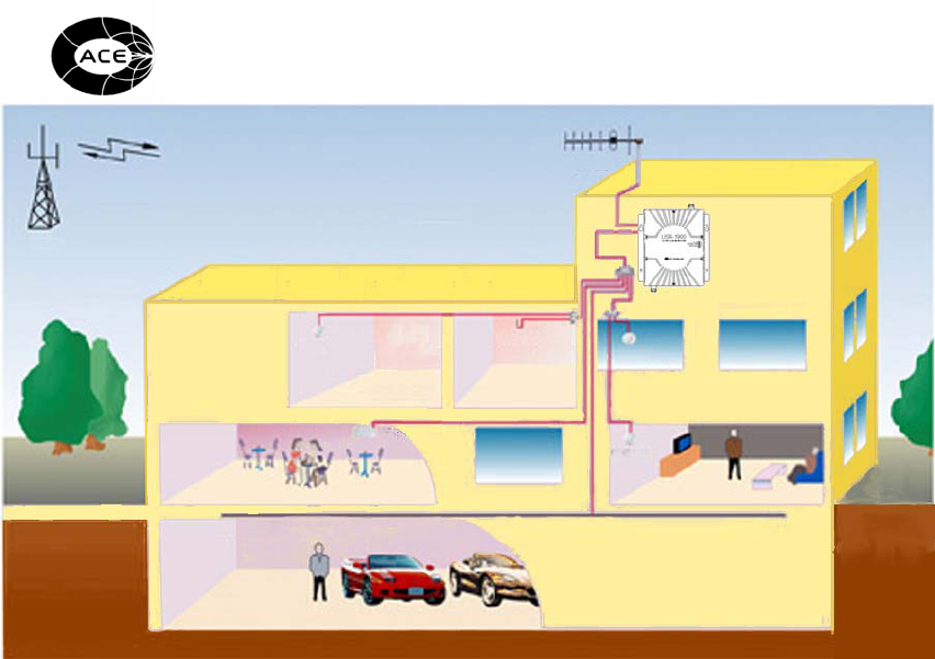
2.8 Installation Example
USHR-1900 can be installed with multiple indoor antennas as shown in Figure 2-8.
In this example, a 6-way power splitter was used to split the signal to and from the
indoor antennas.
<Figure 2-8: USHR-1900 Installation Example>
ACE Antenna
9
3. Operation
3.1 Introduction
This section provides information for operating the USHR-1900 BDA.
3.2 Operating Instruction
3.2.1 Power-up
Connect the BDA to AC/DC Adaptor. If no FAIL condition is present, only the
“POWER” LED will remain lit. The BDA is then operating properly.
3.2.2 Fail Status
3.2.2.1 Overdrive Fail
There is one overdrive fail on the unit, for the up link. Over driving occurs when the
RF output power of the BDA exceeds a prescribed limit. This means that the input
RF power level is too high, or the BDA is oscillating. The condition may be
transient, caused by a passing emergency vehicle emitting a strong signal for
example, or permanent, due to a nearby base station. It may also indicate low
isolation between the antennas, which causes the unit to oscillate (please refer to the
section 2.6.2 of this manual for antenna alignment and isolation.)
The overdrive fail on the USHR-1900 BDA is design to detect whether the over driving
is transient or permanent. If the output power level of reverse path(=Up Link)
exceeds prescribed limit, then reverse path is disconnected and the FAIL LED

ACE Antenna
10
(RED) is on. BDA automatically checks output power level every 1 minute of a 5
minute cycle when reverse path has over power . If reverse path still exceeds level
then shut down mode continues for another 10 minutes. After 10 minutes, reverse
path is switched on again and it checks output power level again. (Repeats the
process)
4. Trouble Shooting
If the BDA does not operate properly after installation, first make sure that the
installation procedures as described in section 2 of this manual were followed
correctly. Inspect each connection, both RF and AC, and connectors for a secure fit,
checking to see if all the connections are made to the proper ports of the unit and
the antennas.
If the malfunction is due to an alarm condition, refer to the appropriate part of the
section 3.2 of this manual. Corrective actions may be taken for the overdrive
alarms.
There are no user serviceable parts in the USHR-1900.
DO NOT OPEN the unit. There is a danger of an electric
shock. Opening the covers of the unit will void all warranties.
CAUTION!
ACE Antenna
11
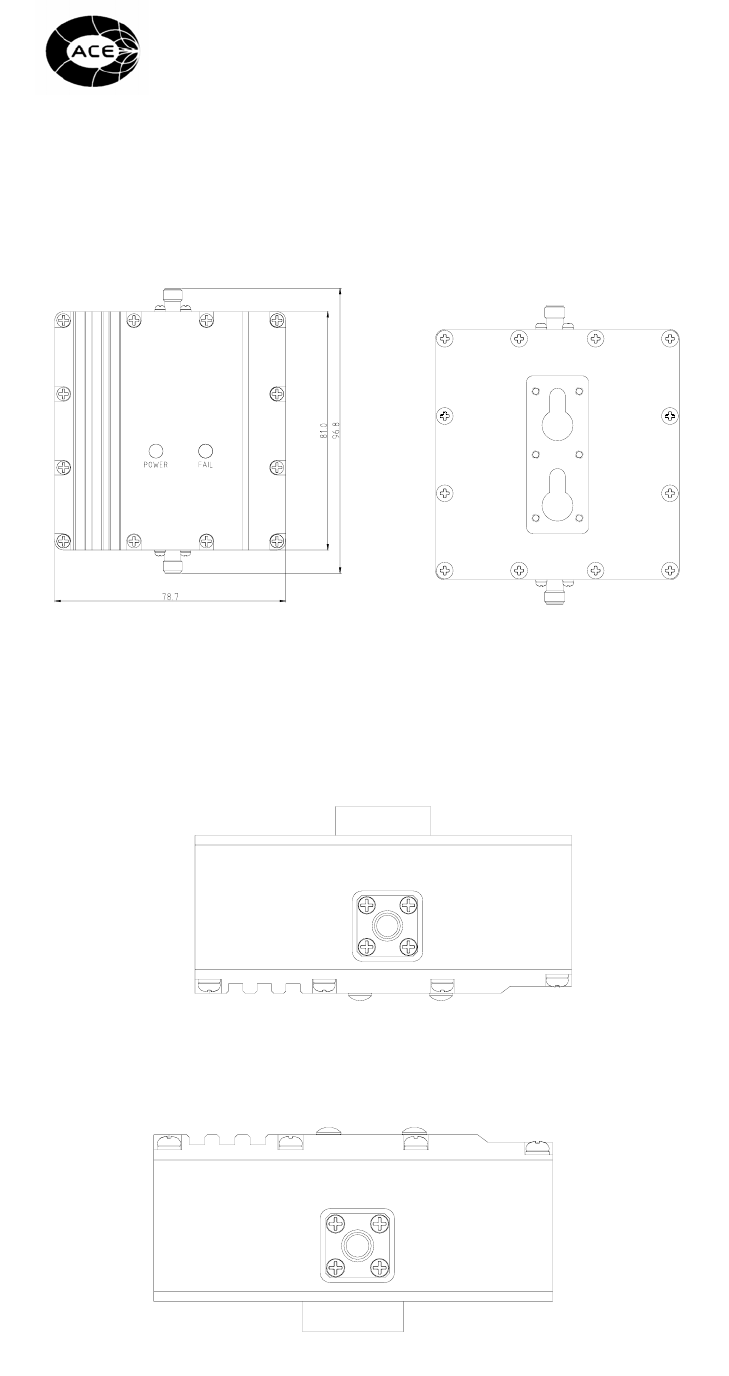
5. Drawings
5.1 Front and Back views
<Figure 5-1: USHR-1900 Front and Back views>
5.2 Top and Bottom views
<Figure 5-2: USHR-1900 Top and Bottom views>
TO MOBILE
TOP
BOTTOM
ACE Antenna
12
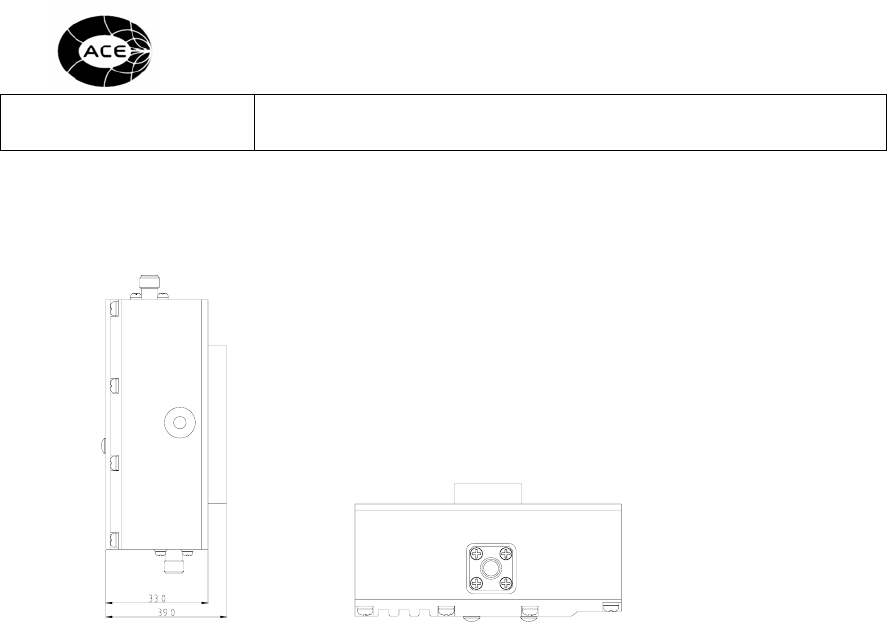
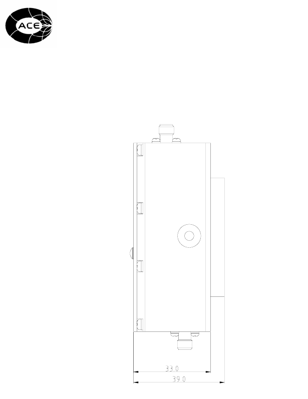
5.3 Side views
<Figure 5-3: USHR-1900 Side views>
DC IN