Acer orporated TMC110BG Notebook Computer with WLAN Mini PCI Card User Manual TMC110 en
Acer Incorporated Notebook Computer with WLAN Mini PCI Card TMC110 en
Contents
- 1. User Manual 1
- 2. User Manual 2
- 3. User Manual 3
- 4. User Guide
User Manual 3
51
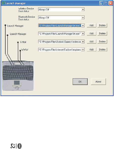
Launch Manager
Launch Manager allows you to set the four launch keys located above
the keyboard. See “Launch keys” on page 24 for the location of the
launch key.
You can access the Launch Manager by clicking on Start, All
Programs, and then Launch Manager to start the application.
Launch Manager and wireless features
The boot status settings for Wireless Device (Wireless LAN) and
Bluetooth Device determine if these wireless features are enabled or
disabled at startup.
You can manually switch on or off Wireless LAN and Bluetooth by
pressing the button a certain number of times. The sequence is
as follows:
• Wireless LAN off, Bluetooth off
• Wireless LAN on, Bluetooth off (wireless status icon lights red)
• Wireless LAN off, Bluetooth on (wireless status icon flashes green)
• Wireless LAN on, Bluetooth on (wireless status icon lights red and
flashes green)
TMC110-en.book Page 51 Monday, March 3, 2003 4:46 PM
2 Customizing your computer52
Manually turning on the wireless features does not change the default
boot status setting which is re-enabled when you restart your
computer.
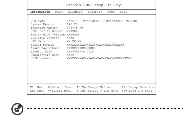
BIOS Utility
The BIOS Utility is a hardware configuration program built into your
computer’s BIOS (basic input/output system).
Your computer is already properly configured and optimized, and you
do not need to run this utility. However, if you encounter
configuration problems, you may need to run it.
To access the BIOS Utility, press F2 during the POST (power-on self-test)
while the TravelMate logo is being displayed.
Note: The sample screen shown above is for your reference only.
Actual values may differ.
For optimum settings, press F9 to load setup defaults. Then press F10
to save the changes and exit the BIOS Utility.
TMC110-en.book Page 52 Monday, March 3, 2003 4:46 PM

3 Troubleshooting your
computer
TMC110-en.book Page 53 Monday, March 3, 2003 4:46 PM

This chapter instructs you on how to deal
with common system problems. Read it
before calling a technician if a problem
occurs. Solutions to more serious problems
require opening up the computer. Do not
attempt to open the computer by yourself.
Contact your dealer or an authorized
service center for assistance.
key link: www.acersupport.com
TMC110-en.book Page 54 Monday, March 3, 2003 4:46 PM
55
Frequently-asked questions
The following is a list of possible situations that may arise during the
use of your computer. Easy answers and solutions are provided for
each one.
I pressed the power switch and opened the display, but the computer
does not start or boot-up.
Look at the Power indicator (refer to “Indicators” on page 18):
• If it is not lit, no power is being applied to the computer. Check
the following:
• If you are running on battery power, it may be low and unable
to power the computer. Connect the AC adapter to recharge
the battery pack.
• Make sure that the AC adapter is plugged in properly to the
computer and to the power outlet.
• If it is lit, check the following:
• Is a non-bootable (non-system) diskette in the floppy drive?
Remove or replace it with a system diskette and press Ctrl-Alt-
Del to restart the system.
• The operating system files may be damaged or missing. Insert the
startup disk you created during Windows setup into the floppy
drive and press Ctrl-Alt-Del to restart the system. This will
diagnose your system and make necessary fixes.
Nothing appears on the screen.
The computer’s power management system automatically blanks the
screen to save power. Press any key to turn the display back on.
If pressing a key does not turn the display back on, three things might
be the cause:
• The brightness level might be too low. Press Fn-→ (increase) and
Fn-← (decrease) to adjust the brightness level.
• The display device might be set to an external monitor. Press the
display toggle hot key Fn-F5 to toggle the display back to the
computer.
• If the Sleep indicator is lit, the computer is in Sleep mode. Press,
slide, and release the power switch to resume.
TMC110-en.book Page 55 Monday, March 3, 2003 4:46 PM
3 Troubleshooting your computer56
Image is not full-screen.
Make sure that the resolution is set to 1024x768 which the system
supports natively. Right-click on your Windows desktop and select
Properties to bring up the Display Properties dialog box. Then click
on the Settings tab to make sure the resolution is set to the
appropriate resolution. Resolutions lower than the specified
resolution are not full-screen on the computer or on an external
monitor.
No audio is heard from the computer.
Check the following:
• The volume may be muted. In Windows, look at the volume
control (speaker) icon on the taskbar. If it is crossed-out, click on
the icon and deselect the Mute option.
• The speakers may be turned off. Press Fn-F8 to turn the speakers
on (this hot key also turns the speakers off).
• The volume level may be too low. In Windows, look at the volume
control icon on the taskbar. You can also use the volume control
buttons to adjust the volume. See “Hot keys” on page 21.
• If headphones, earphones or external speakers are connected to
the line-out port on the computer’s right panel, the internal
speakers automatically turn off.
The keyboard does not respond.
Try attaching an external keyboard to the USB connector on the
computer’s rear. If it works, contact your dealer or an authorized
service center as the internal keyboard cable may be loose.
The infrared port does not work.
Check the following:
• Make sure that the infrared ports of the two devices are facing
each other (+/- 15 degrees) a maximum of 1 meter apart.
• Make sure that there is a clear path between the two infrared
ports. Nothing should be blocking the ports.
• Make sure that you have the appropriate software running on
both devices (for file transfers) or that you have the appropriate
drivers (for printing to an infrared printer).
• During the POST, press F2 to access the BIOS Utility and verify that
TMC110-en.book Page 56 Monday, March 3, 2003 4:46 PM
57
the infrared port is enabled.
• Make sure that both devices are IrDA-compliant.
I want to set up my location to use the internal modem.
To properly use your communications software (e.g., HyperTerminal),
you need to set up your location:
1Click on Start, Control Panel.
2Double-click on Phone and Modem Options.
3Begin setting up your location.
Refer to the Windows manual.
TMC110-en.book Page 57 Monday, March 3, 2003 4:46 PM
3 Troubleshooting your computer58
Troubleshooting tips
This notebook computer incorporates an advanced design that delivers
onscreen error message reports to help you solve problems.
• If the system reports an error message or an error symptom occurs,
see “Error messages” on page 59.
TMC110-en.book Page 58 Monday, March 3, 2003 4:46 PM

59
Error messages
If you receive an error message, note the message and take the
corrective action. The following table lists the error messages in
alphabetical order together with the recommended course of action.
Note: If your system displays one of the messages marked below
with an asterisk (*), write down the message and contact your
dealer. If your system fails after you have made the changes in the
Setup menus, reset the computer, enter Setup and load the Setup
defaults to correct the error.
Error Messages Corrective Action
0200 Failure Fixed Disk Fixed disk is not working or not configured
properly. Check to see if fixed disk is
attached properly. Run Setup. Find out if the
fixed-disk type is correctly identified.
0210 Stuck key Stuck key on keyboard.
0211 Keyboard error Keyboard not working.
0212 Keyboard Controller
Failed* Keyboard controller failed test. May require
replacing keyboard controller.
0213 Keyboard locked -
Unlock key switch Unlock the system to proceed.
0220 Monitor type does not
match CMOS - Run SETUP Monitor type not correctly identified in
Setup
0230 Shadow Ram Failed at
offset: nnnn*
Shadow RAM failed at offset nnnn of the
64k block at which the error was detected.
0231 System RAM Failed at
offset: nnnn* System RAM failed at offset nnnn of in the
64k block at which the error was detected.
0232 Extended RAM Failed
at offset: nnnn*
Extended memory not working or not
configured properly at offset nnnn.
0250 System battery is dead
- Replace and run SETUP The CMOS clock battery indicator shows the
battery is dead. Replace the battery and run
Setup to reconfigure the system.
TMC110-en.book Page 59 Monday, March 3, 2003 4:46 PM

3 Troubleshooting your computer60
0251 System CMOS
checksum bad - Default
configuration used
System CMOS has been corrupted or
modified incorrectly, perhaps by an
application program that changes data
stored in CMOS. The BIOS installed Default
Setup Values. If you do not want these
values, enter Setup and enter your own
values. If the error persists, check the system
battery or contact your dealer.
0260 System timer error* The timer test failed. Requires repair of
system board.
0270 Real time clock error* Real-Time Clock fails BIOS hardware test.
May require board repair.
0271 Check date and time
settings BIOS found date or time out of range and
reset the Real-Time Clock. May require
setting legal date (1991-2099).
0280 Previous boot
incomplete - Default
configuration used
Previous POST did not complete successfully.
POST loads default values and offers to run
Setup. If the failure was caused by incorrect
values and they are not corrected, the next
boot will likely fail. On systems with control
of wait states, improper Setup settings can
also terminate POST and cause this error on
the next boot. Run Setup and verify that the
wait-state configuration is correct. This error
is cleared the next time the system is booted.
0281 Memory Size found by
POST differed from CMOS Memory size found by POST differed from
CMOS.
02B0 Diskette drive A error
02B1 Diskette drive B error Drive A: or B: is present but fails the BIOS
POST diskette tests. Check to see that the
drive is defined with the proper diskette
type in Setup and that the diskette drive is
attached correctly.
02B2 Incorrect Drive A type -
run SETUP Type of floppy drive A: not correctly
identified in Setup.
02B3 Incorrect Drive B type -
run SETUP Type of floppy drive B: not correctly
identified in Setup.
Error Messages Corrective Action
TMC110-en.book Page 60 Monday, March 3, 2003 4:46 PM

61
02D0 System cache error -
Cache disabled RAM cache failed and BIOS disabled the
cache. On older boards, check the cache
jumpers. You may have to replace the cache.
See your dealer. A disabled cache slows
system performance considerably.
02F0: CPU ID: CPU socket number for Multi-Processor error.
02F4: EISA CMOS not
writeable* ServerBIOS2 test error: Cannot write to EISA
CMOS.
02F5: DMA Test Failed* ServerBIOS2 test error: Cannot write to
extended DMA (Direct Memory Access)
registers.
02F6: Software NMI Failed* ServerBIOS2 test error: Cannot generate
software NMI (Non-Maskable Interrupt).
02F7: Fail-Safe Timer NMI
Failed* ServerBIOS2 test error: Fail-Safe Timer takes
too long.
device Address Conflict Address conflict for specified device.
Allocation Error for: device Run ISA or EISA Configuration Utility to
resolve resource conflict for the specified
device.
Failing Bits: nnnn* The hex number nnnn is a map of the bits at
the RAM address which failed the memory
test. Each 1 (one) in the map indicates a
failed bit. See errors 230, 231, or 232 above
for offset address of the failure in System,
Extended, or Shadow memory.
Invalid System
Configuration Data Problem with NVRAM (CMOS) data.
I/O device IRQ conflict I/O device IRQ conflict error.
One or more I2O Block
Storage Devices were
excluded from the Setup
Boot Menu
There was not enough room in the IPL table
to display all installed I2O block-storage
devices.
Error Messages Corrective Action
TMC110-en.book Page 61 Monday, March 3, 2003 4:46 PM

3 Troubleshooting your computer62
If you still encounter problems after going through the corrective
measures, please contact your dealer or an authorized service center
for assistance. Some problems may be solved using the BIOS Utility.
Operating system not found Operating system cannot be located on
either drive A: or drive C:. Enter Setup and
see if fixed disk and drive A: are properly
identified.
Parity Check 1 nnnn* Parity error found in the system bus. BIOS
attempts to locate the address and display it
on the screen. If it cannot locate the address,
it displays nnnn. Parity is a method for
checking errors in binary data. A parity error
indicates that some data has been corrupted.
Parity Check 2 nnnn* Parity error found in the I/O bus. BIOS
attempts to locate the address and display it
on the screen. If it cannot locate the address,
it displays nnnn.
Press <F1> to resume, <F2>
to Setup, <F3> for previous Displayed after any recoverable error
message. Press <F1> to start the boot process
or <F2> to enter Setup and change the
settings. Press <F3> to display the previous
screen (usually an initialization error of an
Option ROM, i.e., an add-on card). Write
down and follow the information shown on
the screen.
Run the I2O Configuration
Utility One or more unclaimed block storage
devices have the Configuration Request bit
set in the LCT. Run an I2O Configuration
Utility (e.g. the SAC utility).
Error Messages Corrective Action
TMC110-en.book Page 62 Monday, March 3, 2003 4:46 PM
63
Requesting service
International Traveler’s Warranty (ITW)
Your computer is backed by an International Traveler’s Warranty (ITW)
that gives you security and peace of mind when traveling. Our
worldwide network of service centers are there to give you a helping
hand.
An ITW passport comes with your computer. This passport contains all
you need to know about the ITW program. A list of available,
authorized service centers are in this handy booklet. Read this
passport thoroughly.
Always have your ITW passport on hand, especially when you travel to
receive the benefits from our support centers. Place your proof-of-
purchase in the flap located inside the front cover of the ITW passport.
If the country you are traveling in does not have an Acer-authorized
ITW service site, you can still get in contact with our offices worldwide.
There are three ways to access Acer for technical support and
information:
• Internet service worldwide, visit http://www.acersupport.com/
• Telephone support in the United States and Canada, call 1-800-
816-2237
• Technical support numbers in various countries
You can view a list of technical support numbers by following these
steps:
1Click on Start, Settings, Control Panel.
2Double-click on System.
3Click on the Support Information button.
Before you call
Please have the following information available when you call Acer for
online service, and please be at your computer when you call. With
your support, we can reduce the amount of time a call takes and help
solve your problems efficiently.
TMC110-en.book Page 63 Monday, March 3, 2003 4:46 PM
3 Troubleshooting your computer64
If there are error messages or beeps reported by your computer, write
them down as they appear on the screen (or the number and sequence
in the case of beeps).
If you haven’t registered your notebook computer, you will be required
to register during your first call to Acer.
You are required to provide the following information:
Name:________________________________________
Address:______________________________________
______________________________________________
Telephone number:____________________________
Machine and model type:_______________________
Serial number:_________________________________
Date of purchase:______________________________
TMC110-en.book Page 64 Monday, March 3, 2003 4:46 PM

Appendix A
Specifications
TMC110-en.book Page 65 Monday, March 3, 2003 4:46 PM

This appendix lists the general
specifications of your computer.
TMC110-en.book Page 66 Monday, March 3, 2003 4:46 PM
67
Microprocessor platform
•Intel® Centrino™ Mobile Technology
• Intel® Pentium® M Processor with 1 MB level 2 cache
• Intel® 855GM chipset family
• Intel® PRO/wireless network connection
Memory
• Main memory expandable to 2 GB
• Dual 200-pin soDIMM sockets supporting PC2100 DDR (Double
Data Rate) memory running at 266 MHz
• 512 KB Flash ROM BIOS
Data storage
• One 9.5mm, high-capacity, Enhanced-IDE hard disk
Display and video
• 10.4"Thin-Film Transistor (TFT) liquid-crystal display (LCD)
displaying 24-bit true-color at 1024x768 eXtended Graphics Array
(XGA) resolution
• Integrated VGA with DVMT support
• 3D capabilities
• Simultaneous LCD and CRT display support
• Dual display capability
• Tablet mode for LCD panel (Rotatable display)
Audio
• 16-bit AC’ 97 PCI stereo audio with built-in wavetable synthesizer
• Built-in speaker and microphone
• Sound Blaster Pro and Windows Sound System-compatible
• Separate audio ports for headphone-out and line-in devices
TMC110-en.book Page 67 Monday, March 3, 2003 4:46 PM
Appendix A Specifications68
Keyboard and pointing device
• Acer FineTouch keyboard
• Ergonomically-centered touchpad pointing device with scroll
function
• Electromagnetic resonance (EMR) stylus for pen-based input
I/O ports
•Built-in:
• One type II/I CardBus PC Card slot
• One RJ-11 phone jack
• One RJ-45 LAN jack
• One DC-in jack (AC adapter)
• One external monitor port
• One speaker/headphone-out jack
• One line-in jack
• One FIR wireless communications port (IrDA-compliant)
• Two USB 2.0 ports
• One IEEE 1394 port
• One EasyPort port replicator connector
Weight and dimensions
• 3.2 lbs (1.40 kg)
• 257 (W) x 216 (D) x 29.7 (H) mm
Environment
• Temperature
• Operating: 10°C ~ 35°C
• Non-operating: -20°C ~ 60°C
• Humidity (non-condensing)
• Operating: 20% ~ 80% RH
• Non-operating: 20% ~ 80% RH
TMC110-en.book Page 68 Monday, March 3, 2003 4:46 PM
69
System
• Microsoft Windows XP Tablet PC Edition
• ACPI support
• DMI 2.0-compliant
• LDCM 6.0 support
Power
• Battery pack
• 26 WattHour Li-ion main battery pack
• Smart battery management technology
• 1.5-hour rapid charge/2.5-hour charge-in-use
• AC adapter
• 50-Watt
• Auto sensing 100~240Vac, 50~60Hz
Options
• Memory upgrade modules
• Higher-capacity hard disk drive
• USB optical drive
• USB floppy disk drive
• IEEE 1394 optical drive
• Additional AC adapter
• Additional Li-ion battery pack
• External battery charger
• Full size EMR pen with eraser
•EMR stylus
• Bluetooth/Modem combo module
• 802.11b, 802.11a, or 802.11a/b wireless LAN module
• Acer EasyPort port replicator
TMC110-en.book Page 69 Monday, March 3, 2003 4:46 PM
Appendix A Specifications70
TMC110-en.book Page 70 Monday, March 3, 2003 4:46 PM

Appendix B
Notices
TMC110-en.book Page 71 Monday, March 3, 2003 4:46 PM

This appendix lists the general
notices of your computer.
TMC110-en.book Page 72 Monday, March 3, 2003 4:46 PM
73
FCC notice
This device has been tested and found to comply with the limits for a Class B
digital device pursuant to Part 15 of the FCC Rules. These limits are designed to
provide reasonable protection against harmful interference in a residential
installation. This device generates, uses, and can radiate radio frequency
energy and, if not installed and used in accordance with the instructions, may
cause harmful interference to radio communications.
However, there is no guarantee that interference will not occur in a particular
installation. If this device does cause harmful interference to radio or television
reception, which can be determined by turning the device off and on, the user
is encouraged to try to correct the interference by one or more of the following
measures:
• Reorient or relocate the receiving antenna
• Increase the separation between the device and receiver
• Connect the device into an outlet on a circuit different from that to which
the receiver is connected
• Consult the dealer or an experienced radio/television technician for help
Notice: Shielded cables
All connections to other computing devices must be made using shielded cables
to maintain compliance with FCC regulations.
Notice: Peripheral devices
Only peripherals (input/output devices, terminals, printers, etc.) certified to
comply with the Class B limits may be attached to this equipment. Operation
with non-certified peripherals is likely to result in interference to radio and TV
reception.
Caution
Changes or modifications not expressly approved by the manufacturer could
void the user’s authority, which is granted by the Federal Communications
Commission, to operate this computer.
Use conditions
This part complies with Part 15 of the FCC Rules. Operation is subject to the
following two conditions: (1) this device may not cause harmful interference,
and (2) this device must accept any interference received, including interference
that may cause undesired operation.
TMC110-en.book Page 73 Monday, March 3, 2003 4:46 PM
Appendix B Notices74
Notice: Canadian users
This Class B digital apparatus meets all requirements of the Canadian
Interference-Causing Equipment Regulations.
Remarque à l’intention des utilisateurs canadiens
Cet appareil numérique de la classe B respected toutes les exigences du
Règlement sur le matériel brouilleur du Canada.
Modem notices
FCC
This equipment complies with Part 68 of the FCC rules. Located on the bottom
side of the modem is a label that contains, among other information, the FCC
Registration Number and Ringer Equivalence Number (REN) for this equipment.
Upon request, you must provide this information to your telephone company.
If your telephone equipment causes harm to the telephone network, the
telephone company may discontinue your service temporarily. If possible, they
will notify you in advance. But, if advance notice is not practical, you will be
notified as soon as possible. You will also be informed of your right to file a
complaint with the FCC.
Your telephone company may make changes in its facilities, equipment,
operations, or procedures that could affect the proper functioning of your
equipment. If they do, you will be notified in advance to give you an
opportunity to maintain uninterrupted telephone service.
If this equipment should fail to operate properly, disconnect the equipment
from the phone line to determine if it is causing the problem. If the problem is
with the equipment, discontinue use and contact your dealer or vendor.
TBR 21
This equipment has been approved [Council Decision 98/482/EC - “TBR 21”] for
pan-European single terminal connection to the Public Switched Telephone
Network (PSTN). However, due to differences between the individual PSTNs
provided in different countries, the approval does not, of itself, give an
unconditional assurance of successful operation on every PSTN termination
point. In the event of problems, you should contact your equipment supplier in
the first instance.
TMC110-en.book Page 74 Monday, March 3, 2003 4:46 PM
75
Important safety instructions
Read these instructions carefully. Save these instructions for future reference.
1Follow all warnings and instructions marked on the product.
2Unplug this product from the wall outlet before cleaning. Do not use
liquid cleaners or aerosol cleaners. Use a damp cloth for cleaning.
3Do not use this product near water.
4Do not place this product on an unstable cart, stand, or table. The product
may fall, causing serious damage to the product.
5Slots and openings in the cabinet and the back or bottom are provided for
ventilation; to ensure reliable operation of the product and to protect it
from overheating, these openings must not be blocked or covered. The
openings should never be blocked by placing the product on a bed, sofa,
rug, or other similar surface. This product should never be placed near or
over a radiator or heat register, or in a built-in installation unless proper
ventilation is provided.
6This product should be operated from the type of power indicated on the
marking label. If you are not sure of the type of power available, consult
your dealer or local power company.
7Do not allow anything to rest on the power cord. Do not locate this
product where persons will walk on the cord.
8If an extension cord is used with this product, make sure that the total
ampere rating of the equipment plugged into the extension cord does not
exceed the extension cord ampere rating. Also, make sure that the total
rating of all products plugged into the wall outlet does not exceed the fuse
rating.
9Never push objects of any kind into this product through cabinet slots as
they may touch dangerous voltage points or short out parts that could
result in a fire or electric shock. Never spill liquid of any kind on the
product.
10 Do not attempt to service this product yourself, as opening or removing
covers may expose you to dangerous voltage points or other risks. Refer all
servicing to qualified service personnel.
11 Unplug this product from the wall outlet and refer servicing to qualified
service personnel under the following conditions:
aWhen the power cord or plug is damaged or frayed
bIf liquid has been spilled into the product
cIf the product has been exposed to rain or water
dIf the product does not operate normally when the operating
instructions are followed. Adjust only those controls that are covered
by the operating instructions since improper adjustment of other
TMC110-en.book Page 75 Monday, March 3, 2003 4:46 PM
Appendix B Notices76
controls may result in damage and will often require extensive work
by a qualified technician to restore the product to normal condition.
eIf the product has been dropped or the cabinet has been damaged
fIf the product exhibits a distinct change in performance, indicating a
need for service.
12 Replace the battery with the same type as the product's battery we
recommend. Use of another battery may present a risk of fire or explosion.
13 Warning! Batteries may explode if not handled properly. Do not
disassemble or dispose of them in fire. Keep them away from children and
dispose of used batteries promptly.
14 Use only the proper type of power supply cord set (provided in your
accessories box) for this unit. It should be a detachable type: UL listed/CSA
certified, type SPT-2, rated 7A 125V minimum, VDE approved or its
equivalent. Maximum length is 15 feet (4.6 meters).
Regulatory Information
The MPCI-101 Wireless LAN Card must be installed and used in strict accordance
with the manufacturer’s instructions. This device complies with the following
radio frequency and safety standards.
Canada - Industry Canada (IC)
•This device complies with RSS 210 of Industry Canada.
Europe - EU Declaration of Conformity
This device complies with the specifications listed below, following the
provisions of the EMC Directive 89/336/EEC:
•ETS 300-826
•ETS 300-328 Technical requirements for Radio equipment.
USA - Federal Communications Commission (FCC)
This device complies with Part 15 of FCC Rules. Operation of the devices in an
MPCI-101 Wireless LAN System is subject to the following two conditions:
•This device may not cause harmful interference.
•This device must accept any interference that may cause undesired
operation.
Exposure to Radio Frequency Radiation
This transmitter must not be co-located or operating in conjunction with any
other antenna or transmitter.
TMC110-en.book Page 76 Monday, March 3, 2003 4:46 PM

77
The transmitter and the antenna are permanently installed inside the
notebook, and are specific for this model (not for generic computer).
This equipment has been tested and found to comply with the limits for a Class
B digital device, pursuant to Part 15 of the FCC Rules. These limits are designed
to provide reasonable protection against harmful interference in a residential
installation. This equipment generates, uses and can radiate radio frequency
energy and, if not installed and used in accordance with the instructions, may
cause harmful interference to radio communications. However, there is no
guarantee that interference will not occur in a particular installation. If this
equipment does cause harmful interference to radio or television reception,
which can be determined by turning the equipment off and on, the user is
encouraged to try to correct the interference by one of the following measures:
•Reorient or relocate the receiving antenna.
•Increase the separation between the equipment and receiver.
•Connect the equipment into an outlet on a circuit different from that to
which the receiver is connected.
•Consult the dealer or an experienced radio/TV technician for help.
FCC Caution: To assure continued compliance, any changes or modifications not
expressly approved by the party responsible for compliance could void the
user's authority to operate this equipment (example - use only shielded
interface cables when connecting to computer or peripheral devices).
This device complies with Part 15 of the FCC Rules. Operation is subject to the
following two conditions: (1) This device may not cause harmful interference,
and (2) this device must accept any interference received, including interference
that may cause undesired operation.
Responsible Party: Acer America Corporation, 2641 Orchard Parkway, San Jose,
CA 95134
Telephone No:1-408-432-6200
TMC110-en.book Page 77 Monday, March 3, 2003 4:46 PM

78 Appendix B Notices
Federal Communications Commission
Declaration of Conformity
This device complies with Part 15 of the FCC Rules. The test result has been shown in the ISL test
report with number 04LR001FC. Operation is subject to the following two conditions: (1) this
device may not cause harmful interference, and (2) this device must accept any interference received,
including interference that may cause undesired operation.
The following local Manufacturer /Importer is responsible for this declaration:
Product Name: Notebook Personal Computer
Model: MS2133
Name of Responsible Party: Acer America Corporation
Address of Responsible Party: 2641 Orchard Parkeay, San Jose
CA 95134, U. S. A.
Contact Person: Mr. Young Kim
Phone No.: 408-922-2909
Fax No.: 408-922-2606
_________________________
Mr. Young Kim / Director, Quality Management
Acer America Corporation
Jan. 13, 2004
79
Appendix B Notices80
Laser compliance statement
The CD drive used with this computer is a laser product. The CD drive’s
classification label (shown below) is located on the drive.
CLASS 1 LASER PRODUCT
CAUTION: INVISIBLE LASER RADIATION WHEN OPEN. AVOID EXPOSURE TO
BEAM.
APPAREIL A LASER DE CLASSE 1 PRODUIT
LASERATTENTION: RADIATION DU FAISCEAU LASER INVISIBLE EN CAS
D’OUVERTURE. EVITTER TOUTE EXPOSITION AUX RAYONS.
LUOKAN 1 LASERLAITE LASER KLASSE 1
VORSICHT: UNSICHTBARE LASERSTRAHLUNG, WENN ABDECKUNG GEÖFFNET
NICHT DEM STRAHLL AUSSETZEN
PRODUCTO LÁSER DE LA CLASE I
ADVERTENCIA: RADIACIÓN LÁSER INVISIBLE AL SER ABIERTO. EVITE
EXPONERSE A LOS RAYOS.
ADVARSEL: LASERSTRÅLING VEDÅBNING SE IKKE IND I STRÅLEN.
VARO! LAVATTAESSA OLET ALTTINA LASERSÅTEILYLLE.
VARNING: LASERSTRÅLNING NÅR DENNA DEL ÅR ÖPPNAD ÅLÅ TUIJOTA
SÅTEESEENSTIRRA EJ IN I STRÅLEN
VARNING: LASERSTRÅLNING NAR DENNA DEL ÅR ÖPPNADSTIRRA EJ IN I
STRÅLEN
ADVARSEL: LASERSTRÅLING NAR DEKSEL ÅPNESSTIRR IKKE INN I STRÅLEN
Lithium battery statement
CAUTION
Danger of explosion if battery is incorrectly replaced. Replace only with the
same or equivalent type recommended by the manufacturer. Dispose of used
batteries according to local regulations. Recycle if at all possible.
ADVARSEL!
Lithiumbatteri - Eksplosionsfare ved fejlagtig håndtering. Udskiftning må kun
ske med batteri af samme fabrikat og type. Léver det brugte batteri tilbage til
leverandøren.
ADVARSEL
Eksplosjonsfare ved feilaktig skifte av batteri. Benytt samme batteritype eller
en tilsvarende type anbefalt av apparatfabrikanten. Brukte batterier kasseres i
henhold til fabrikantens instruksjoner.
TMC110-en.book Page 80 Monday, March 3, 2003 4:46 PM

81
VARNING
Explosionsfara vid felaktigt batteribyte. Anvãnd samma batterityp eller en
ekvivalent typ som rekommenderas av apparattillverkaren. Kassera anvãnt
batteri enligt fabrikantens instruktion.
VAROITUS
Päristo voi räjähtää, jos se on virheellisesti asennettu. Vaihda paristo
ainoastaan laitevalmistajan suosittelemaan tyyppiin. Hävitä käytetty paristo
valmistajan ohjeiden mukaisesti.
VORSICHT!
Explosionsgefahr bei unsachgemäßen Austausch der Batterie Ersatz nur durch
denselben oder einem vom Hersteller empfohlenem ähnlichen Typ. Entsorgung
gebrauchter Batterien nach Angaben des Herstellers.
Year 2000 compliance statement
The TravelMate C110 series notebook computer carries the "Hardware NSTL
Tested Year 2000 Compliant" logo, which certifies that this model has been
tested by NSTL using the YMark2000 test, and has been found to meet NSTL's
standards for Year 2000 hardware compliance.
LCD pixel statement
The LCD unit is produced with high-precision manufacturing techniques.
Nevertheless, some pixels may occasionally misfire or appear as black or colored
dots. This has no effect on the recorded image and does not constitute a
malfunction.
A-Tick notice
For safety reasons, only connect headsets with a telecommunications
compliance label. This includes customer equipment previously labelled
permitted or certified.
The unit shall be connected to Telecommunication Network through a line cord
which meets the requirements of ACA Technical Standard TS008.
Australian approved mains cord set shall be used with the equipment.
TMC110-en.book Page 81 Monday, March 3, 2003 4:46 PM
Appendix B Notices82
TMC110-en.book Page 82 Monday, March 3, 2003 4:46 PM
83
Index
A
AC adapter
caring for viii
audio 29
adjusting the volume 29
troubleshooting 56
B
battery pack
caring for ix
charging indicator 18
BIOS utility 52
brightness
hotkeys 23
C
caps lock 19
on indicator 18
care AC adapter viii
battery pack ix
computer viii
cleaning
computer ix
computer
bringing to meetings 32
caring for viii
cleaning ix
disconnecting 31
features 3, 16
indicators 18
keyboards 19
moving around 31
on indicator 18
performance 16
security 36
setting up a home office 33
taking home 32
traveling internationally 34
traveling on local trips 34
troubleshooting 54
turning off viii
Wireless Communication indica-
tor 18
Configuring tablet mode buttons 5
connections
network 44
contrast
hotkeys 23
D
display
hotkeys 22
troubleshooting 55, 56
E
email checking function 25
error messages 59
Euro 23
F
FAQ 55
front view 3
H
hard disk 28
help online services 63
Hibernation mode
hotkey 22
hotkeys 21
I
indicator lights 18
infrared 45
troubleshooting 56
ITW. See warranty
K
keyboard 19
embedded numeric keypad 20
hotkeys 21
lock keys 19
troubleshooting 56
Windows keys 21
L
LEDs 18
M
media access
on indicator 18
memory
installing 49– 50
TMC110-en.book Page 83 Monday, March 3, 2003 4:46 PM
84
upgrading 49
messages
error 59
modem 43
N
network 44
Notebook Manager 50
hotkey 22
notice
year 2000 compliance 81
num lock 19
on indicator 18
numeric keypad
embedded 20
num lock 20
O
online services 63
options
memory upgrade 49
P
password 36
types 36
PC Card 47
ejecting 47
inserting 47
ports 43
POST (power-on self-test) 52
problems
display 55, 56
infrared 56
keyboard 56
startup 55
troubleshooting 54
Q
questions
setting location for modem use
57
R
Rotating the display in tablet mode
4
S
safety
CD-ROM 80
FCC notice 73
general instructions 75
lithium battery 80
modem notices 74
scroll lock 19
security
keylock 36
passwords 36
smart card 36
service
when to call ix
speakers
hotkey 22
troubleshooting 56
specifications 66
Standby mode
hotkey 22
status indicator 18
status indicators 18
storage 28
hard disk 28
support
information 63
T
Tablet mode button
enter button 4
function key button 5
page down button 4
page up button 4
windows security button 5
touchpad 26
hotkey 22
using 26– 27
travel
international flights 34
local trips 34
troubleshooting 54
tips 58
U
universal serial bus (USB) 45
Using computer in tablet mode 10
V
viewfront 6
left 6
rear 8
right 7
TMC110-en.book Page 84 Monday, March 3, 2003 4:46 PM
85
volume
adjusting 29
W
warranty
International Traveler’s Warran-
ty 63
Windows keys 21
TMC110-en.book Page 85 Monday, March 3, 2003 4:46 PM
86
TMC110-en.book Page 86 Monday, March 3, 2003 4:46 PM