Acer 1507550698User Manual 1.0 A
User Manual: Acer ACER ALTOS T110 F4 pdf | FreeUserManuals.com
Open the PDF directly: View PDF ![]() .
.
Page Count: 60

2
Workstation
Altos T110 F4
USER’S MANUAL
Revision 1.0

SuperWorkstation 5039D-I User's Manual
Preface
3
4
Preface
About this Manual
This manual is written for professional system integrators and PC technicians. It provides
information for the installation and use of the Workstation. Installation and maintainance
should be performed by experienced technicians only.
Notes
For your system to work properly, please follow the links below to download all necessary
drivers/utilities and the user’s manual for your workstation.
•
product manuals:
Warnings
Special attention should be given to the following symbols used in this manual.
Warning! Indicates important information given to prevent equipment/property damage
or personal injury.
Warning! Indicates high voltage may be encountered when performing a procedure.
Table of Contents
Chapter 1 Introduction
1.1 Overview ............................................................................................................................. 8
1.2 Unpacking the System ........................................................................................................ 8
1.3 System Specifications ......................................................................................................... 9
1.4 Server Chassis Features .................................................................................................. 10
Control Panel ................................................................................................................... 10
Front Features ................................................................................................................. 11
Rear Features ................................................................................................................. 12
1.5 Motherboard Layout .......................................................................................................... 13
Quick Reference Table ............................................................................................................. 14
Chapter 2 Workstation Setup
2.1 Overview ........................................................................................................................... 17
2.2 Preparing for Setup .......................................................................................................... 17
Choosing a Setup Location ............................................................................................. 17
Server Precautions .......................................................................................................... 17
Chapter 3 Maintenance and Component Installation
3.1 Removing Power .............................................................................................................. 19
3.2 Accessing the System ...................................................................................................... 19
3.3 Motherboard Components ................................................................................................ 20
Processor and Heatsink Installation ................................................................................ 20
Memory Installation ......................................................................................................... 25
Memory Support .......................................................................................................... 25
DIMM Module Population Sequence ............................................................................... 26
PCI Expansion Card Installation ...................................................................................... 27
Motherboard Battery ........................................................................................................ 27
3.4 Chassis Components ........................................................................................................ 28
Hard Drives ..................................................................................................................... 28
Optional Drive Bays ......................................................................................................... 30
System Cooling ............................................................................................................... 31
Replacing the System Fan ........................................................................................... 31
Power Supply .................................................................................................................. 32

SuperWorkstation 5039D-I User's Manual
Preface
5
6
Chapter 4 Motherboard Connections
4.1 Power Connections ........................................................................................................... 33
4.2 Headers and Connectors .................................................................................................. 34
Control Panel ............................................................................................................... 39
Data Cables ................................................................................................................. 42
Power Cables ............................................................................................................... 42
4.3 Ports ................................................................................................................................. 43
Rear I/O Ports .............................................................................................................. 43
4.4 Jumpers ............................................................................................................................ 45
Explanation of Jumpers ................................................................................................ 45
4.5 LED Indicators .................................................................................................................. 49
Chapter 5 Software
5.1 OS Installation .................................................................................................................. 51
Installing the Windows OS for a RAID System ................................................................ 51
Installing Windows to a Non-RAID System ...................................................................... 51
5.2 Driver Installation .............................................................................................................. 52
5.3 SuperDoctor® 5 .................................................................................................................. 53
5.4 IPMI .................................................................................................................................. 54
Chapter 6 BIOS
6.1 Introduction ....................................................................................................................... 55
Starting the Setup Utility .................................................................................................. 55
6.2 Main Setup ....................................................................................................................... 56
6.3 Advanced Setup Configurations ........................................................................................ 58
6.4 Event Logs ........................................................................................................................ 83
6.5 IPMI .................................................................................................................................. 85
6.6 Security ............................................................................................................................. 88
6.7 Boot .................................................................................................................................. 91
6.8 Save & Exit ....................................................................................................................... 93
Appendix A BIOS Error Codes
Appendix B Standardized Warning Statements for AC Systems
Appendix C System Specifications
7
Chapter 1: Introduction
Chapter 1
Introduction
1.1 Overview
This chapter provides a brief outline of the functions and features of the T110 F4.
In additon to the motherboard and chassis, several important parts that are included with the
system are listed below.
Main Parts List
Description
Part Number
Quantity
Fans (4-cm, PWM)
FAN-0108L4
1
Internal 3.5" HDD Drive Trays
MCP-220-73101-0B
4
1.2 Unpacking the System
Inspect the box the Workstation T110 F4 was shipped in and note if it was damaged in any
way. If any equipment appears damaged, please file a damage claim with the carrier who
delivered it.
The system should be situated in a clean, dust-free area that is well ventilated. Avoid areas
where heat, electrical noise and electromagnetic fields are generated. It will also require a
grounded AC power outlet nearby. Be sure to read the precautions and considerations noted
in Appendix B.
SuperWorkstation 5039D-I User's Manual
Chapter 1: Introduction
8
9
1.3 System Specifications
The following table provides you with an overview of the main features and specifications of
the T110 F4. Please refer to Appendix C for additional specifications.
1.4 System Chassis Features
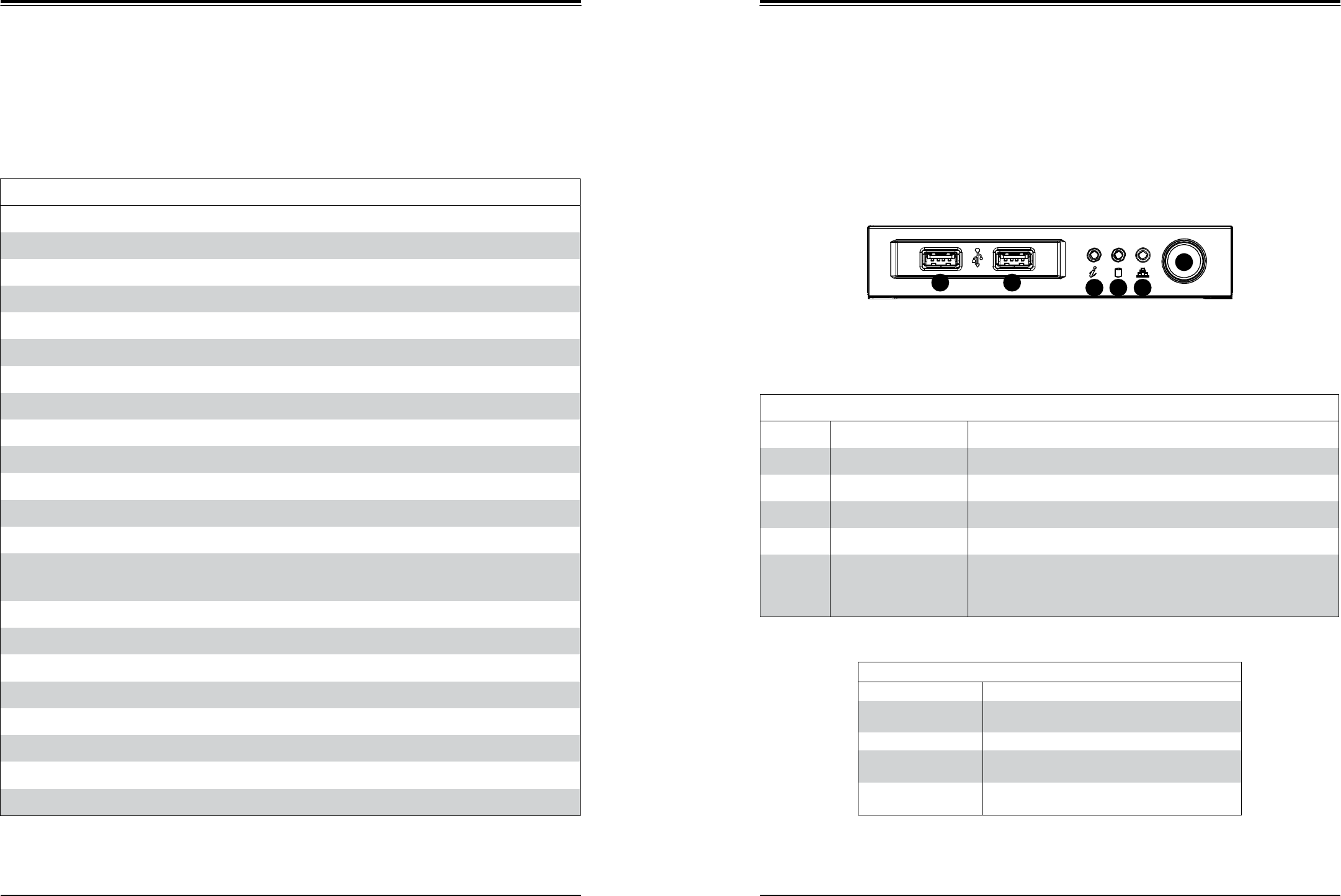
Control Panel
The switches and LEDs located on the control panel are described below. See Chapter 4 for
more details on the control panel.
Figure 1-1. Control Panel View
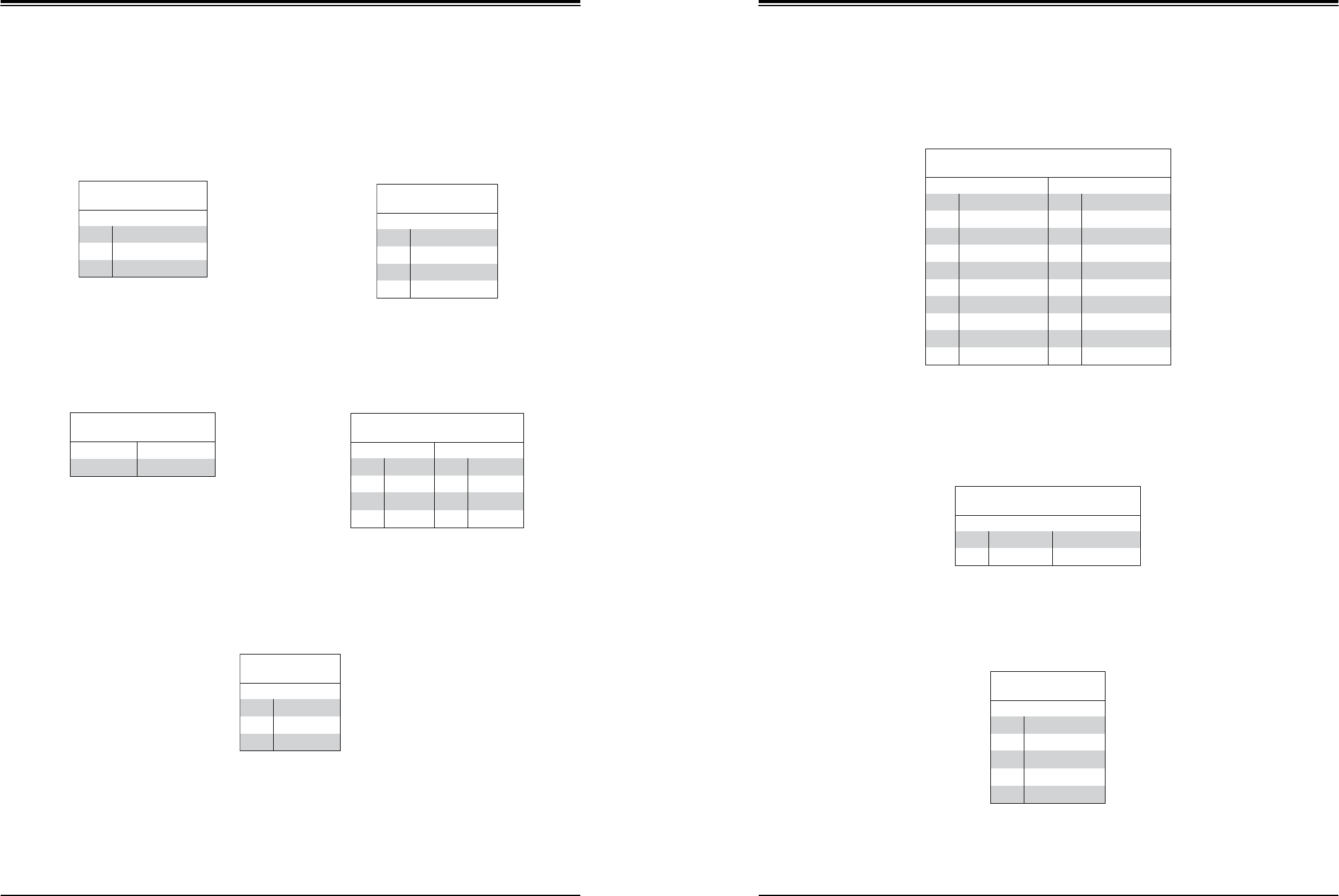
Control Panel Features
Item
Feature
Description
1
USB Port
Front access USB port
2
Information LED
See table below
3
HDD LED
Indicates activity on the hard drive when flashing
4
NIC1 LED
Indicates network activity on the LAN port when flashing
5
Power Button
The main power button is used to apply or remove power from the power supply
to the server. Turning off system power with this button removes the main power
but maintains standby power. To perform many maintenance tasks, you must
also unplug system before servicing
Information LED
Status
Description
Continuously on and red
An overheat condition has occured.
(This may be caused by cable congestion.)
Blinking red (1Hz)
Fan failure, check for an inoperative fan.
Solid blue
Local UID has been activated. Use this function to
locate the server in a rackmount environment.
Blinking blue
Remote UID is on. Use this function to identify the
server from a remote location.
5
1
1
2 3 4
System Specifications
Motherboard
X11SSL-F
Chassis
SC731i-300B
CPU
Intel® E3-1200 v5 and 6th Gen Core™ i3, Pentium and Celeron processors
Socket Type
LGA 1151 (H4)
Memory
Four 288-pin DIMM slots to support up to 64 GB of 72-bit, unbuffered ECC DDR4-2133/1866/1600/1333 SDRAM
Chipset
C232 chipset
Expansion Slots
One PCI Express 3.0 x4 in x8 slots (PCH slot 5)
One PCI Express 3.0 x8 in x16 slot (CPU slot 6)
One PCI Express 3.0 x8 slot (CPU slot 7)
Hard Drives
Up to four 3.5" internal drives
Power
Single 300W low-noise power supply with PFC
Form Factor
Mini tower
Dimensions
(WxHxD) 7.25 x 14.25 x 16.75 in. (184 x 362 x 425 mm)
SuperWorkstation 5039D-I User's Manual
Chapter 1: Introduction
10
11
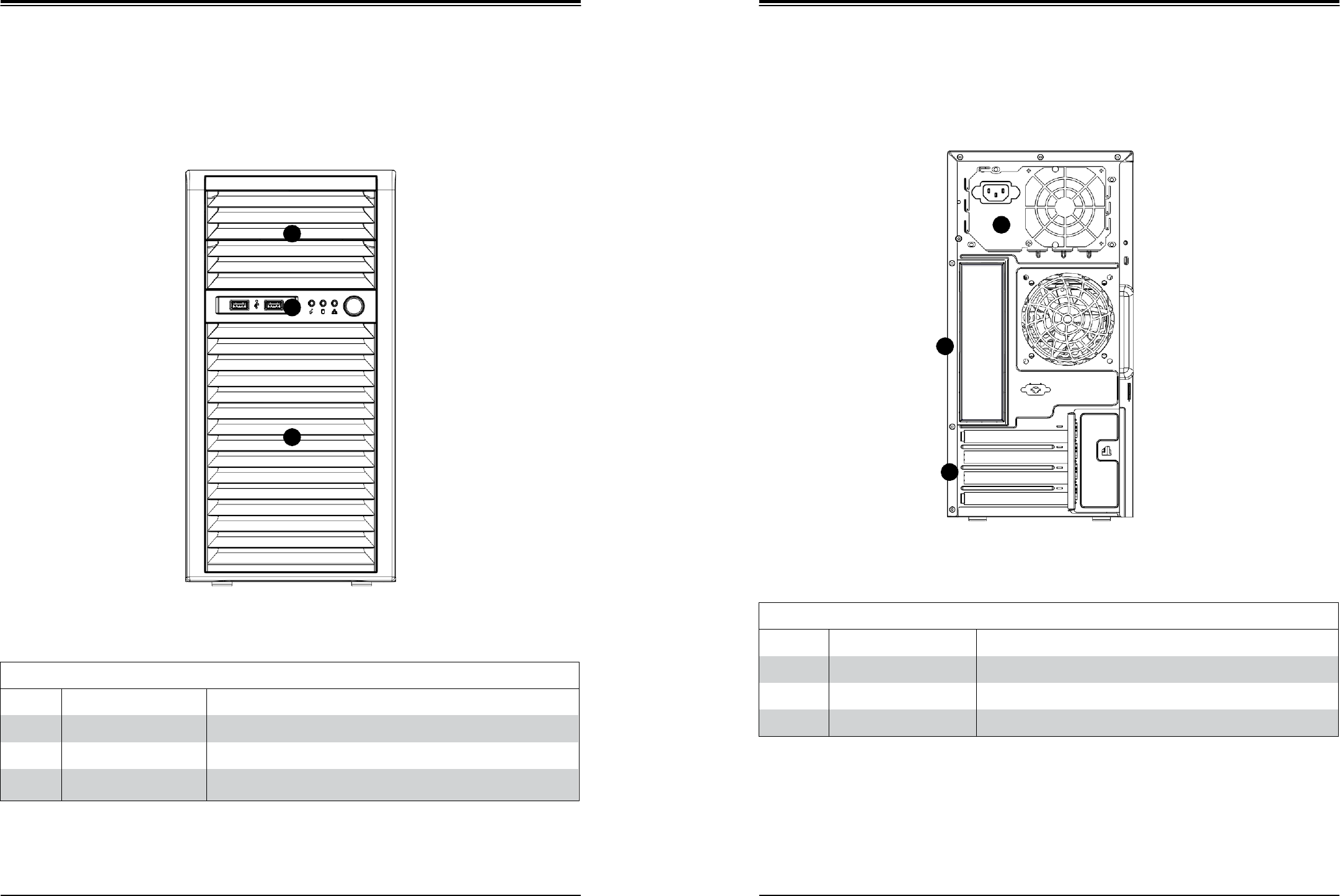
Front Features
The T110 F4 is a mini-tower chassis. See the illustration below for the features included on
the front of the chassis.
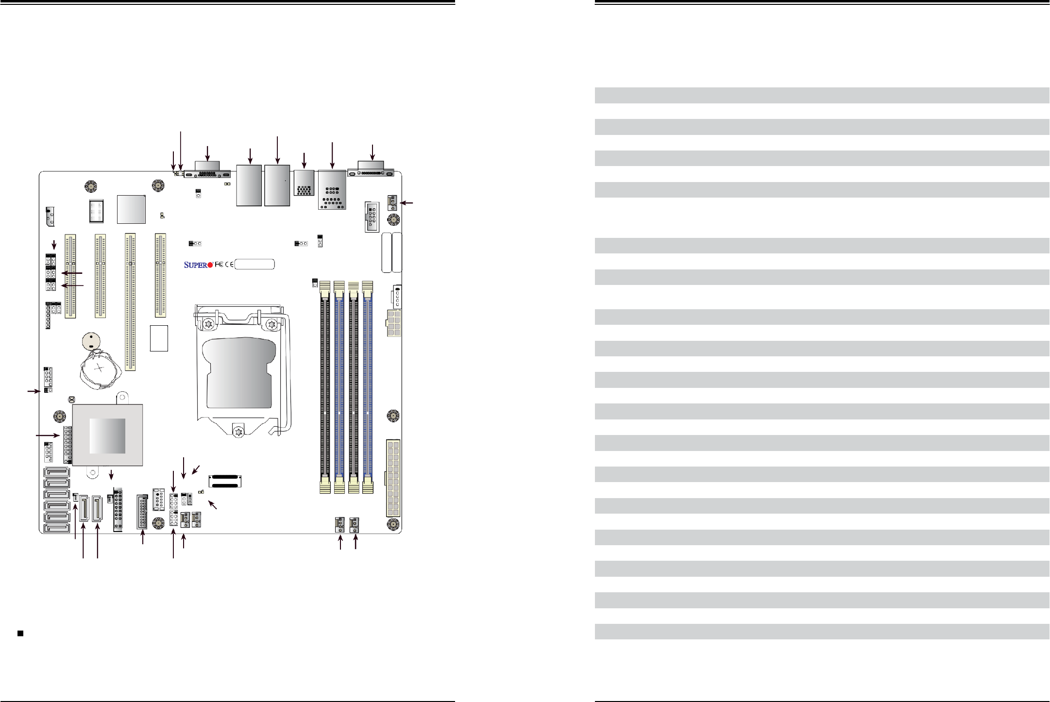
Rear Features
The illustration below shows the features included on the rear of the chassis.
1
1
2
2
3
3
Figure 1-3. Chassis Rear View
Figure 1-2. Chassis Front View
Front Chassis Features
Item
Feature
Description
1
Fixed Drive Area
Supports two fixed 5.25" drives (such as a DVD-ROM or Blu-ray drive)
2
Control Panel
Front control panel with LEDs and buttons (see preceding page)
3
Internal HDD Cage (behind
bezel)
Supports four 3.5" hard drives in a rotatable cage
Rear Chassis Features
Item
Feature
Description
1
Power Supply
300W 80Plus Bronze Level power supply (p/n PWS-305-PQ)
2
I/O Backpanel
Rear I/O ports (see Section 4.3)
3
PCI Slots
Supports four full-height, full-length PCI expansions cards
SuperWorkstation 5039D-I User's Manual
Chapter 1: Introduction
12
13
PCH
SLOT5
PCI-E
3.0
x4(IN
x8)
JPG1
JPME2
JI2C2
JBR1
JPB1
JI2C1
1.5 Motherboard Layout
Below is a layout with jumper, connector and LED locations shown. See the table on the
following page for descriptions. For detailed descriptions, pinout information and jumper
settings, refer to Chapter 5.
JUIDB1
LE1
VGA LAN2
LAN1
USB6/7
IPMI_LAN
USB0/1
COM1
JIPMB1
LE1
JUIDB1
LEDBMC
LED BMC
VGA LAN2 LAN1
JOH1
USB6/7
(3.0)
USB0/1
IPMI_LAN
COM1
FAN4
JPG1 JPL2
JPL2
JPL1
JPL1
JBR1
JPB1
JI2C1
JD1
SP1
JPME2
JI2C2
SP1
X11SSM(-F)/X11SSL(-F)
REV:1.01
Designed in the USA
MAC CODE
JPI2C1
JPWR2
USB2/3
JL1
USB2/3
JL1
BT1
JBT1 BT1
JBT1
CPU
JTPM1
USB4/5
I-SATA5
I-SATA7
Intel PCH
JSD1
JF1
I-SGPIO1
USB10
USB10(3.0)
JWD1 JSTBY1
JPWR1
I-SATA4
I-SATA3
I-SATA2
I-SATA2
JSD2
JF1
LED PWR
FANA FAN3
FAN3
LEDPWR
FAN2 FAN1
I-SATA1
USB8/9
I- SATA0
FANA
I-SGPIO2 FAN2 FAN1
Figure 1-4. Motherboard Layout
Notes:
" " indicates the location of pin 1.
Jumpers/LED indicators not indicated are used for test purposes only.
The COM2, PCI-E Slot 4, I-SATA6 and I-SATA 7 ports shown above are not included on the
X11SSL-F.
Table continued on next page.
BMC
MEGERAC
LICENSE
BAR CODE
IPMI CODE
JPI2C1
FAN4
JPWR2
JPWR1
DIMMB2
COM2
DIMMB1
DIMMA2
DIMMA1
JOH1
JSTBY1
JWD1
CPU
SLOT7
PCI-E
3.0
x8
I-SGPIO1
I-SGPIO2
CPU
SLOT6
PCI-E
3.0
x8(IN
x16)
USB8/9(3.0)
JSD1
I-SATA0
I-SATA1
PCH
SLOT4
PCI-E
3.0
x4(IN
x8)
JSD2
I-SATA3
JTPM1
JIPMB1
JD1
USB4/5
I-SATA6I-SATA5I-SATA4
Quick Reference Table
Jumper
Description
Default Setting
JI2C1/JI2C2
SMB to PCI Slots Enable/Disable
Pins 1-2 (Enabled)
JBR1
BIOS Recovery
Pins 1-2 (Normal)
JBT1
Clear CMOS
Open (Normal)
JPB1
BMC Enable/Disable
Pins 1-2 (Enabled)
JPG1
VGA Enable/Disable
Pins 1-2 (Enabled)
JPL1/JPL2
LAN1/LAN2 Enable/Disable
Pins 1-2 (Enabled)
JPME2
Manufacturing Mode Select
Pins 1-2 (Normal)
JWD1
Watch Dog
Pins 1-2 (Reset)
LED
Description
Status
LE1
Rear UID LED
Blue: On; Unit Identified
LEDBMC
BMC Heartbeat LED
Green: Blinking; BMC Normal
LEDPWR
Onboard Power LED
Green: Sollid On; Power On
Connector
Description
BT1
Onboard Battery
COM1
COM1 (Serial Port) Header
Fan1-Fan4, FanA
System/CPU Fan Headers
(IPMI) LAN
Dedicated IPMI (RJ45) Port
I-SATA0-I-SATA5
(Intel PCH) SATA (Serial ATA) 3.0 Ports
I-SGPIO 1/2
Serial Link General Purpose I/O Headers
JD1
Speaker/Power LED Indicator
JF1
Front Panel Control Header
JIPMB1
4-pin External BMC I2C Header (for an IPMI Card)
JL1
Chassis Intrusion Header
JPI2C1
Power System Management Bus (Power SMB)
JOH1
Overheat LED Indicator
JPWR1
24-pin ATX Main Power Connector (Required Connection)
JPWR2
+12V 8-pin Power Connector
JSD1/JSD2
SATA DOM (Device On Module) Power Connectors
JSTBY1
Inject External P5V Standby Power
JTPM1
Trusted Platform Module/Port 80 Connector
JUIDB1
Unit Identifier Switch
LAN1/LAN2
Gigabit (RJ45) Ports
PCI-E (CPU) Slot 7
PCI-Express 3.0 x8 Slot
PCI-E (CPU) Slot 6
PCI-Express 3.0 x8 in x16 Slot
SuperWorkstation 5039D-I User's Manual
Chapter 1: Introduction
14
15
#A-1
IMVP 8
3 PHASE for Vcore
80W
#B-1
PCIe3.0 x8 (in x8)
PCIe3.0 x8 (in x16)
BMC
AST2400
VGA CONN
COM1
Connector
COM2
Header
Temp Sensor
EMC1402-1 *2 at diff SMBUS
DDR3
BMC Boot Flash
SPI
#A-2
#B-2
PCI-E X8 Gen3
#8-15
PCI-E X8 Gen3
#0-7
Skt-H4
LGA1151
DMI3
DMI3 x4
PCI-E X1 Gen3
PCI-E x4 Gen3
PCI-E X1 Gen3
PCI-E x4 Gen3
RGRMII
RJ45
LAN3
RTL8211E-VB-CG
6.0 Gb/S
PCI-E X1 Gen1
SPI
USB 2.0
USB 3.0
USB 2.0
SPI
SPI
LPC
RJ45
LAN1
I210
#9
#1/2/3/4
#10
#5/6/7/8
PCH
#11
#9
PCIe3.0 x4 (in x8)
RJ45
LAN2
I210
PCIe 3.0 x4 (in x8)
MUX
BIOS
TPM Header
Debug Card
Connector
Description
PCI-E (PCH) Slot 5
PCI-Express 3.0 x4 in x8 Slot
SP1
Internal Speaker/Buzzer
USB 0/1
Back Panel USB 2.0 Ports
USB 2/3, USB 4/5
Front Accessible USB 2.0 Headers
USB 6/7
Back Panel USB 3.0 Ports
USB 8/9
Front Accessible USB 3.0 Header
USB 10
USB 3.0 Type-A Header
VGA
VGA Port
SYSTEM POWER
FAN SPEED CTRL
FRONT PANEL
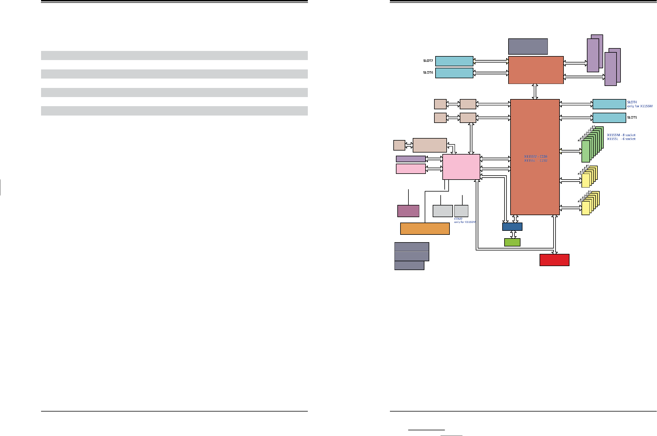
Figure 1-5. C232 Chipset Block Diagram
Note: This is a general block diagram and may not exactly represent the features on your
motherboard. Note the differences marked between the X11SSL-F (included in the T110 F4)
and the X11SSM. See the Appendix C for the actual specifications of your motherboard.
RMII/NCSI
USB2.0
USB3.0
SATA
DDR4
2133
DDR4
2133

SuperWorkstation 5039D-I User's Manual
16
Chapter 2
Workstation Setup
2.1 Overview
This chapter provides advice setting up your system. If your system is not already fully
integrated with processors, system memory etc., refer to Chapter 4 for details on installing
those specific components.
Caution: Electrostatic Discharge (ESD) can damage electronic components. To prevent such
damage to PCBs (printed circuit boards), it is important to use a grounded wrist strap, handle
all PCBs by their edges and keep them in anti-static bags when not in use.
2.2 Preparing for Setup
Precautions
•
Review the electrical and general safety precautions in Appendix B.
•
Use a regulating uninterruptible power supply (UPS) to protect the workstation from power
surges and voltage spikes and to keep your system operating in case of a power failure.
•
Allow any drives and power supply modules to cool before touching them.
•
When not servicing, always keep all covers/panels on the system closed to maintain proper
cooling.

17
Chapter 3: Maintenance and Component Installation
Chapter 3
Maintenance and Component Installation
This chapter provides instructions on installing and replacing main system components. To
prevent compatibility issues, only use components that match the specifications and/or part
numbers given.
Installation or replacement of most components require that power first be removed from the
system. Please follow the procedures given in each section.
3.1 Removing Power
Use the following procedure to ensure that power has been removed from the system. This
step is necessary when removing or installing non hot-swap components or when replacing
a non-redundant power supply.
1. Use the operating system to power down the system.
2. After the system has completely shut-down, disconnect the AC power cord from the
power strip or outlet.
3. Disconnect the power cord from the power supply module.
3.2 Accessing the System
The left side cover of the SC731i-300B must be removed before replacing the system fan or
installing and removing hard drives.
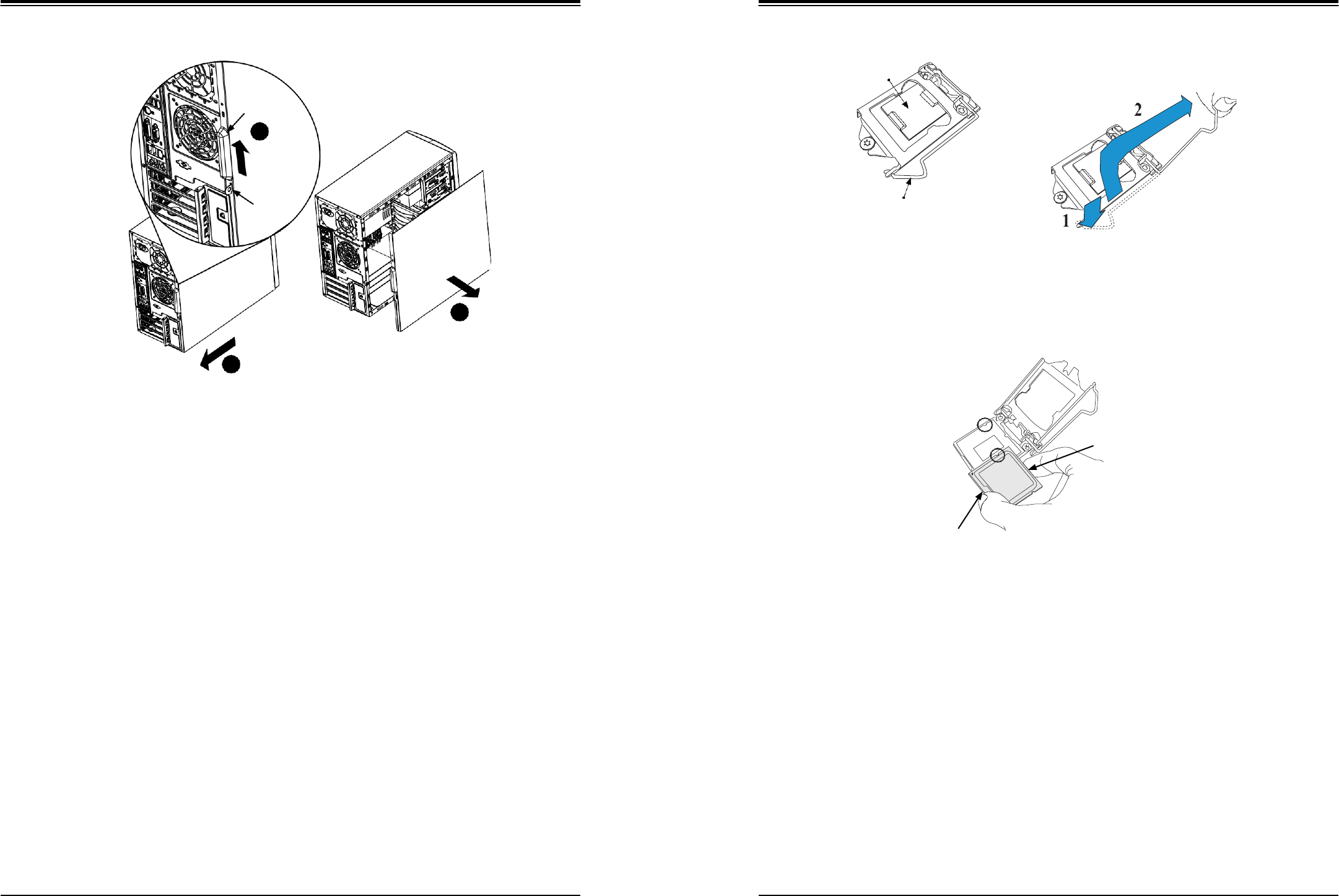
Removing the Top Cover
1. Begin by removing power from the system as described in Section 3.1.
2. Slide the release tab (A) towards the cover handle (B).
3. Grasp the cover handle with your fingers and slide it toward the rear of the chassis
4. Remove the cover from the chassis. See Figure 3-1.
Warning: Except for short periods of time, do not operate the system without the cover in place.
The chassis cover must be in place to allow for proper airflow and to prevent overheating.
SuperWorkstation 5039D-I User's Manual
Chapter 3: Maintenance and Component Installation
18
19
Load Plate
Load Lever
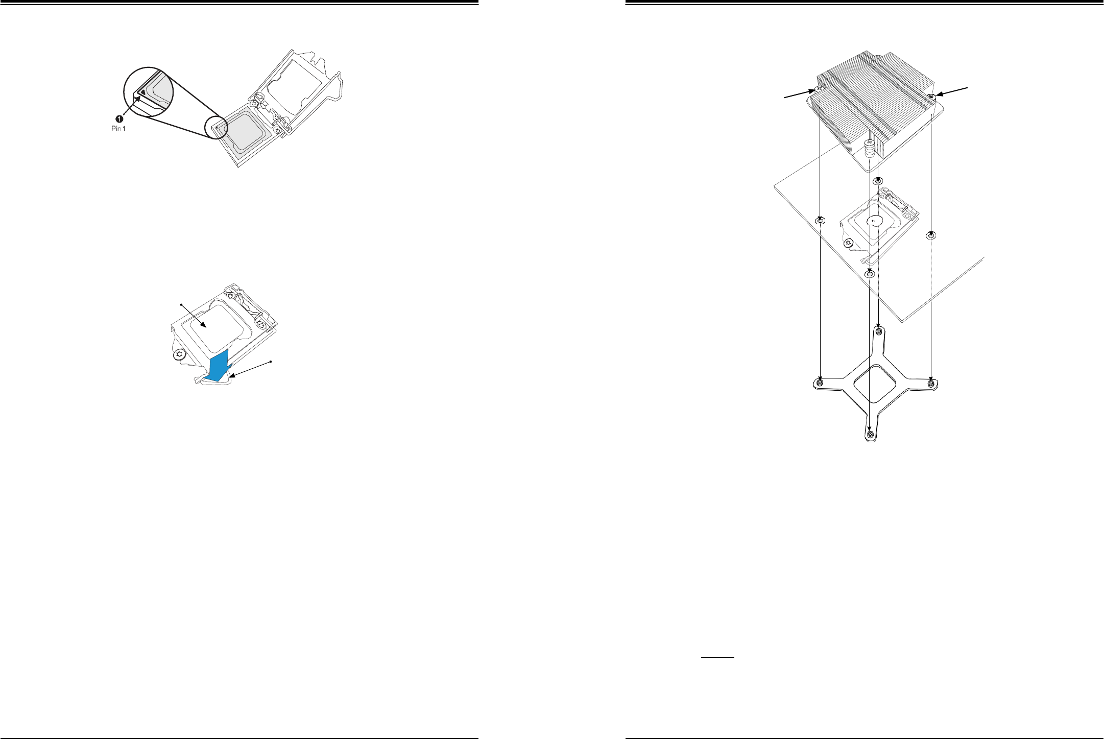
Figure 3-2. Removing the Processor Cover Plate
2. Gently lift the load lever to open the load plate. Remove the plastic cover plate.
Figure 3-1. Accessing the System
3.3 Motherboard Components
Processor and Heatsink Installation
Follow the procedures in this section to install a processor (CPU) and heatsink to the
motherboard.
Notes:
•
The motherboard should be installed into the chassis first and the processor should be
installed into the CPU socket before you install a CPU heatsink.
•
If you bought a CPU separately, make sure that you use an Intel-certified multi-directional
heatsink only.
•
When receiving a motherboard without a processor pre-installed, make sure that the plastic
CPU socket cap is in place and none of the socket pins are bent; otherwise, contact your
retailer immediately.
•
Refer to the Supermicro website for updates on CPU support.
Installing the Processor(s)
Begin by removing power from the system as described in Section 3.1.
1. Remove the cover plate that protects the CPU#1 socket. Lift the lever on the socket until
it points straight up. With the lever raised, lift open the processor retention plate.
Bottom Edge
Figure 3-3. Placing the Processor into the Socket
3. Use your thumb and your index finger to hold the edges of the processor. Align the CPU
key (the semi-circle cutouts) with the socket keys.
4. Once aligned, carefully place the processor into the socket. Do not drop the processor
on the socket, move or rub the processor against the socket or against any socket pins,
which may damage the components.
Top Edge
Cov5
er
3
Handle (B)
2
Slide Tab A
Toward Handle
B
Release Tab
(A)
4
3
SuperWorkstation 5039D-I User's Manual
Chapter 3: Maintenance and Component Installation
20
21
Screw#2
Screw#1
Figure 3-4. Inspecting the Processor Installation
Motherboard
5. With the processor inserted into the socket, inspect the four corners of the CPU to make
sure that it is properly installed and flush with the socket.
Mounting Holes
CPU properly
installed
Load lever locked into
place
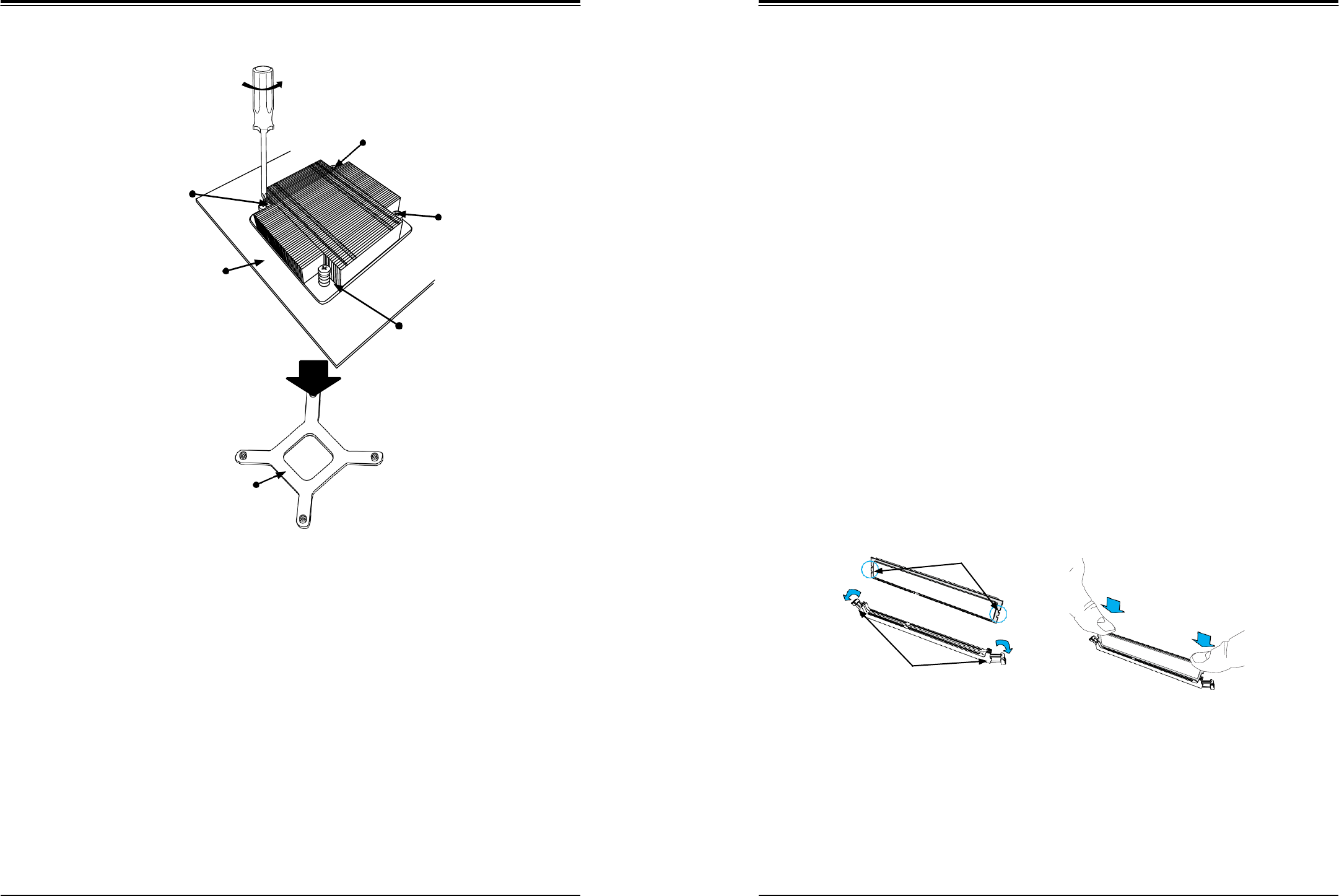
Figure 3-5. Installing/Removing the Heatsink
6. Carefully press the processor load lever down until it locks into its retention tab.
Installing a Heatsink (Example)
1. Place the heat sink on top of the CPU so that the four mounting holes are aligned with
those on the heatsink retention mechanism.
2. Screw in two diagonal screws (i.e. the #1 and the #2 screws) until they are just snug.
Do not fully tighten the screws or you may damage the CPU.
3. Add the two remaining screws then finish the installation by fully tightening all four
screws (be careful not to overtighten).
Heatsink Bracket
Figure 3-6. Installing the Heatsink
Note: The figure above is for illustrative purposes only. A different heatsink may be used in
the 5039D-I
Removing a Heat sink
We do not recommend removing the heatsink. If necessary, please follow the instructions
below to prevent damage to the CPU or the CPU socket.
1. Unscrew and remove the heatsink screws from the motherboard in the sequence as
show in the figure above.
2. Hold and gently pivot the heatsink back and forth to loosen it from the CPU. (Do not use
excessive force when dislodging the heatsink.).
3. Once the heatsink is loose, remove it from the CPU.
SuperWorkstation 5039D-I User's Manual
Chapter 3: Maintenance and Component Installation
22
23
Loosen screws in sequence as
shown.
Screw#1
Motherboard
Screw#4
Screw#2
Memory Installation
Memory Support
The X11SSL-F supports up to 64GB of ECC DDR4-2133/1866/1600/1333 unbuffered (UDIMM)
memory in four memory slots. Populating these DIMM slots with memory modules of the same
type and size will result in interleaved memory, which will improve memory performance.
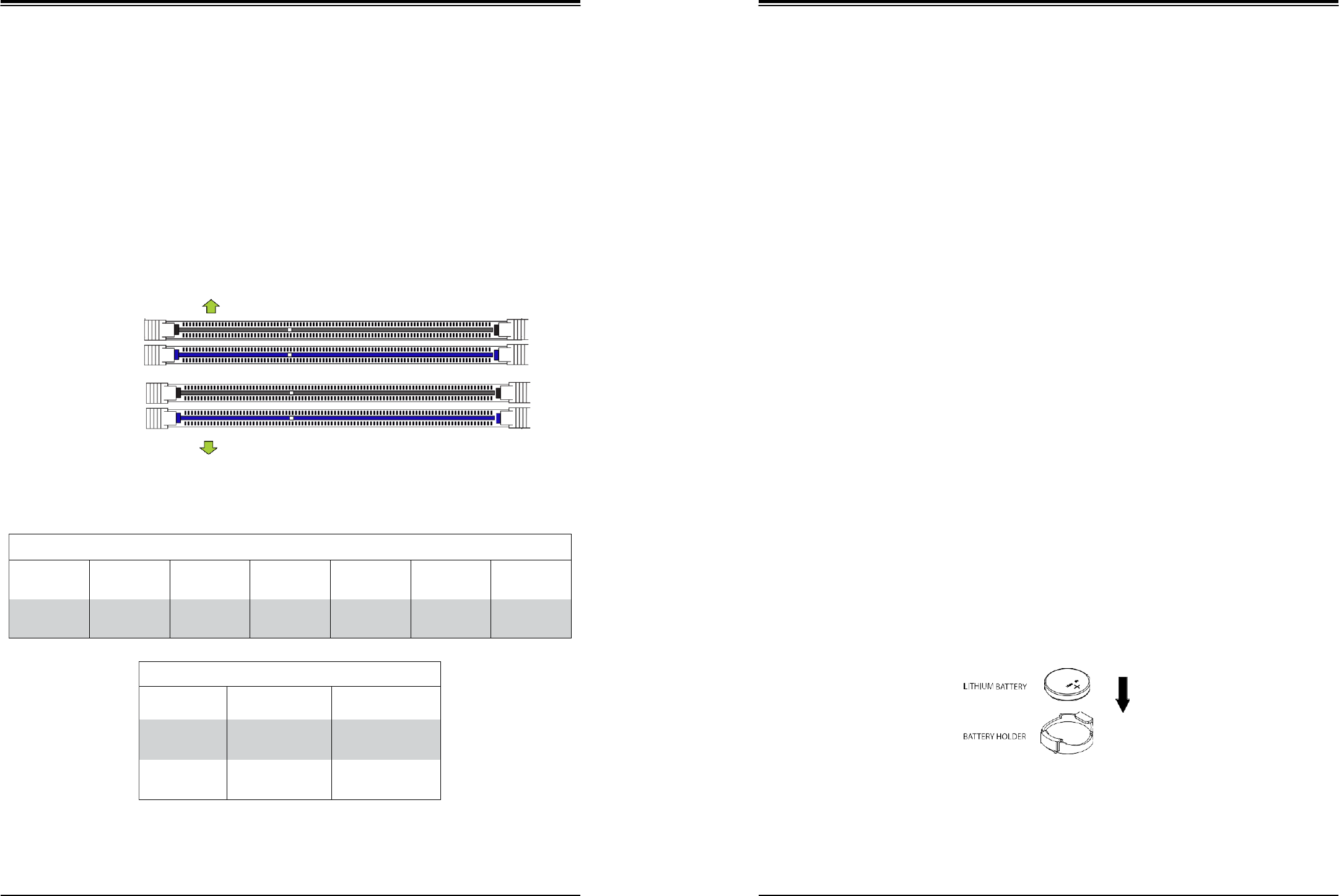
Installing Memory
Begin by removing power from the system as described in Section 3.1.
1. Starting with DIMMB2 (blue slot), push the release tabs outwards on both ends of the
DIMM slot to unlock it.
Heatsink Bracket
Screw#3
2. Align the key of the DIMM with the receptive point on the memory slot and the notches
on both ends of the module with the receptive points on the slot.
3. With your thumbs on both ends of the module, press it straight down into the slot until
the module snaps into place.
4. Press the release tabs to the locked positions to secure the DIMM module into the slot.
Repeat for other DIMM slots as needed. See next page for population sequence.
5. To remove a DIMM, unlock the release tabs then pull the DIMM from the memory slot.
Caution: Exercise extreme caution when installing or removing memory modules to prevent
any possible damage to the DIMMs or slots.
Figure 3-7. Removing the Heatsink
Notches
Note: The figure above is for illustrative purposes only. A different heatsink may be used in
the 5039D-I
4. Clean the surface of the CPU and the heatsink to get rid of the old thermal grease.
Reapply the proper amount of thermal grease to the surface before you re-install the
heatsink.
Release Tabs
Note: Wait for the heatsink to cool down before removing it.
Figure 3-8. Installing DIMMs
Press both notches
straight down into
the memory slot.
SuperWorkstation 5039D-I User's Manual
Chapter 3: Maintenance and Component Installation
24
25
DIMM Module Population Sequence
When installing memory modules, the DIMM slots should be populated in the following order:
DIMMB2, DIMMA2, DIMMB1, DIMMA1.
•
Always use DDR4 DIMM modules of the same type, size and speed.
•
Mixed DIMM speeds can be installed. However, all DIMMs will run at the speed of the
slowest DIMM.
•
The motherboard will support odd-numbered modules (1 or 3 modules installed). However,
for best memory performance, install DIMM modules in pairs to activate memory
interleavng.
Towards the CPU
DIMMA1
DIMMA2 (Blue Slot)
DIMMB1
DIMMB2 (Blue Slot)
Towards the edge of the motherboard
Figure 3-9. Populating DIMMs
PCI Expansion Card Installation
Three standard size PCI expansion (add-on) cards may be installed in the system.
Installing PCI Expansion Cards
Before installing a PCI add-on card, make sure it is supported by the card slot on the
motherboard.
Begin by removing power from the system as described in section 3.1.
1. Remove the chassis cover to access the inside of the system.
2. Remove the PCI slot shield on the chassis by releasing the locking tab.
3. Insert the expansion (add-on) card into the appropriate PCI slot on the motherboard.
4. Secure the card with the locking tab.
Motherboard Battery
The motherboard uses non-volatile memory to retain system information when system power
is removed. This memory is powered by a lithium battery residing on the motherboard.
Replacing the Battery
Begin by removing power from the system as described in section 3.1.
1. Push aside the small clamp that covers the edge of the battery. When the battery is
released, lift it out of the holder.
2. To insert a new battery, slide one edge under the lip of the holder with the positive (+)
side facing up. Then push the other side down until the clamp snaps over it.
Note: Handle used batteries carefully. Do not damage the battery in any way; a damaged
battery may release hazardous materials into the environment. Do not discard a used battery
in the garbage or a public landfill. Please comply with the regulations set up by your local
hazardous waste management agency to dispose of your used battery properly.
Figure 3-10. Installing the Onboard Battery
Warning: There is a danger of explosion if the onboard battery is installed upside down (which
reverses its polarities). This battery must be replaced only with the same or an equivalent type
recommended by the manufacturer (CR2032).
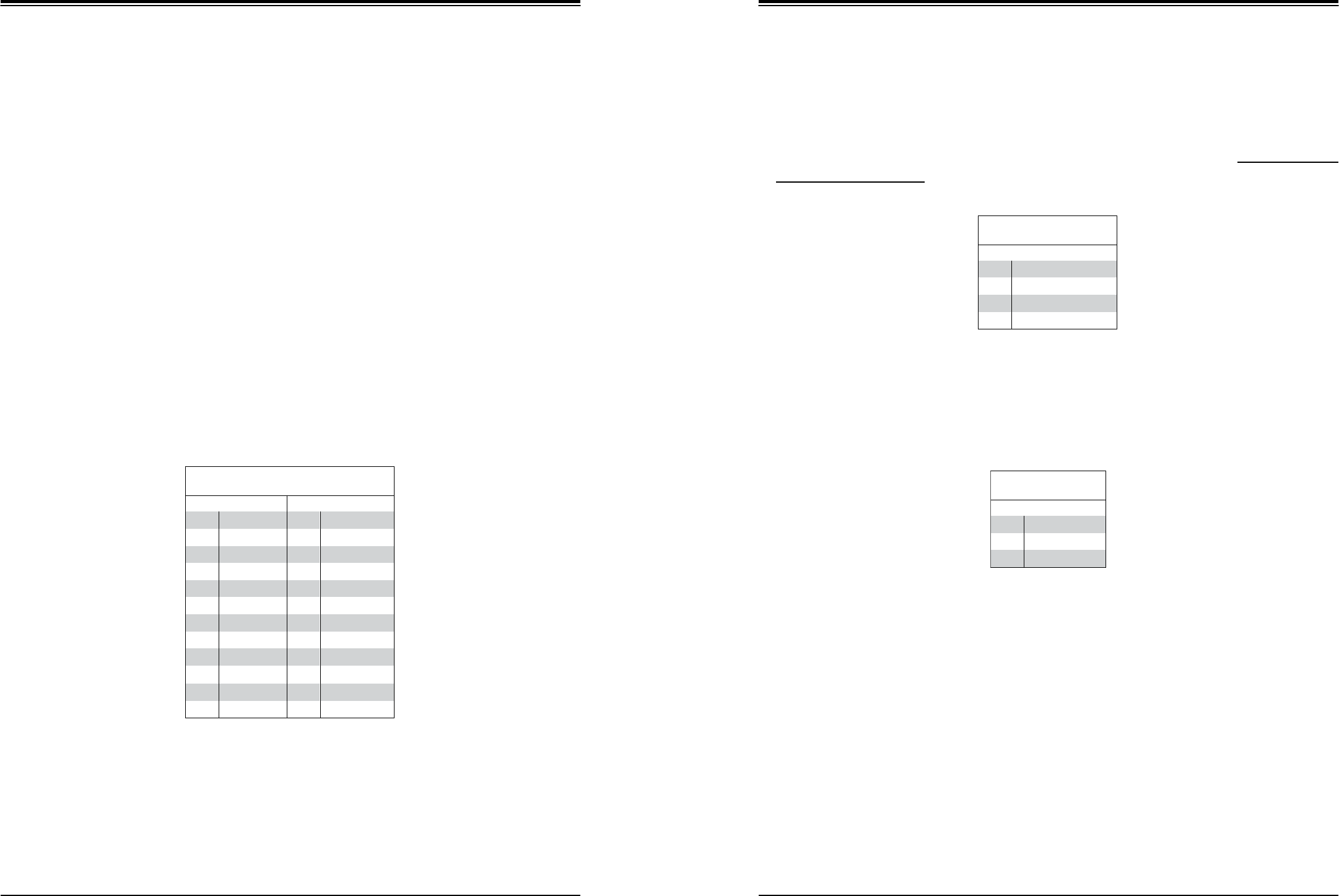
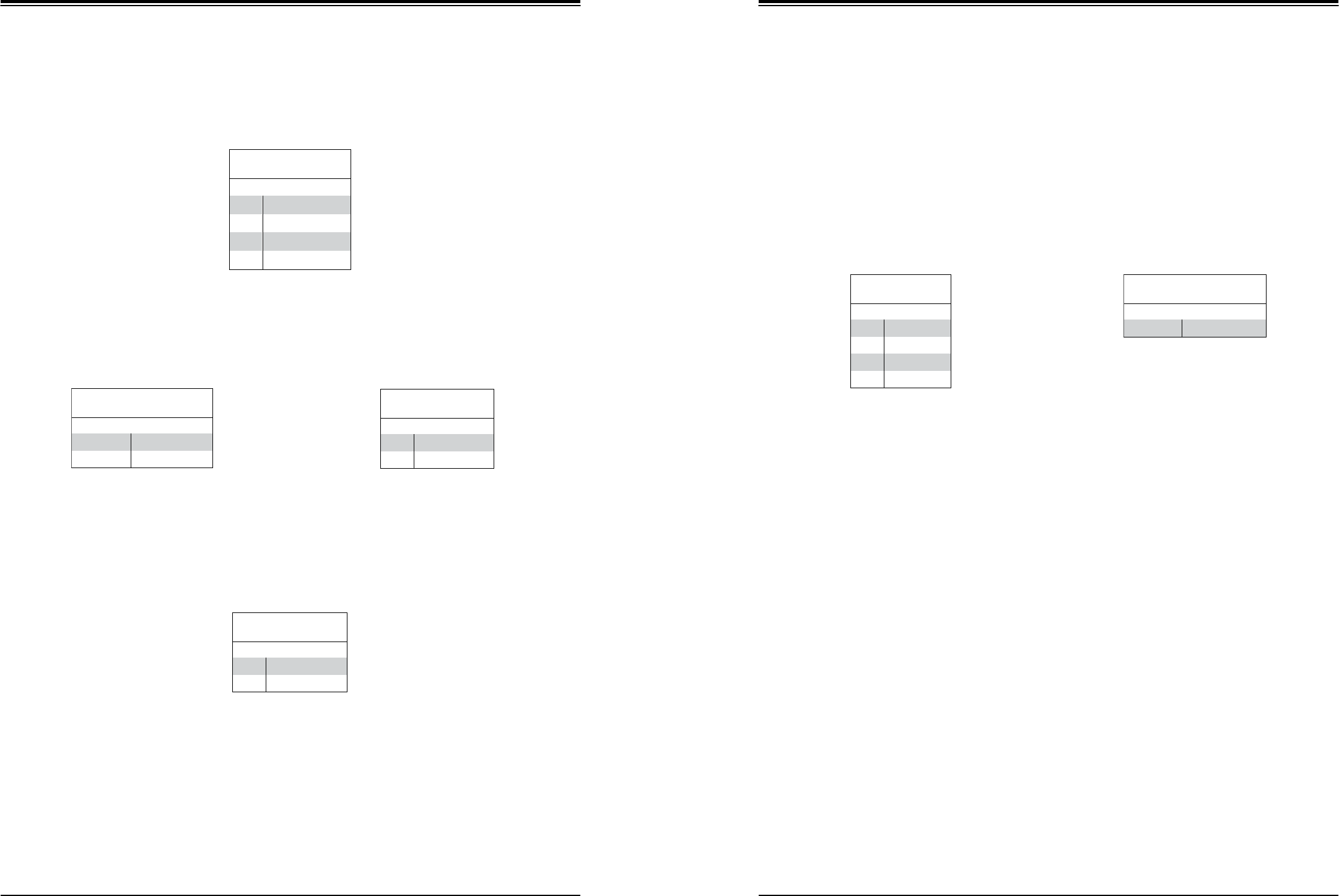
Memory Module Population
DIMM Slots
per Channel
DIMM Type
POR
Speeds
Ranks per
DIMM
Layer
Count
FW Base
Supported
Voltage
2
Unbuffered
DDR4 ECC
2133,1866,
1600, 1333
SR, DR
6
SPS
1.2V
Memory Module Population
Max Memory
Possible
4GB DRAM
Technology
8GB DRAM
Technology
Single Rank
UDIMM
16GB
(4x 4GB DIMMs)
32GB
(4x 8GB DIMMs)
Dual Rank
UDIMMs
32GB
(4x 8GB DIMMs)
64GB
(4x 16GB DIMMs)
SuperWorkstation 5039D-I User's Manual
Chapter 3: Maintenance and Component Installation
26
27
3.4 Chassis Components
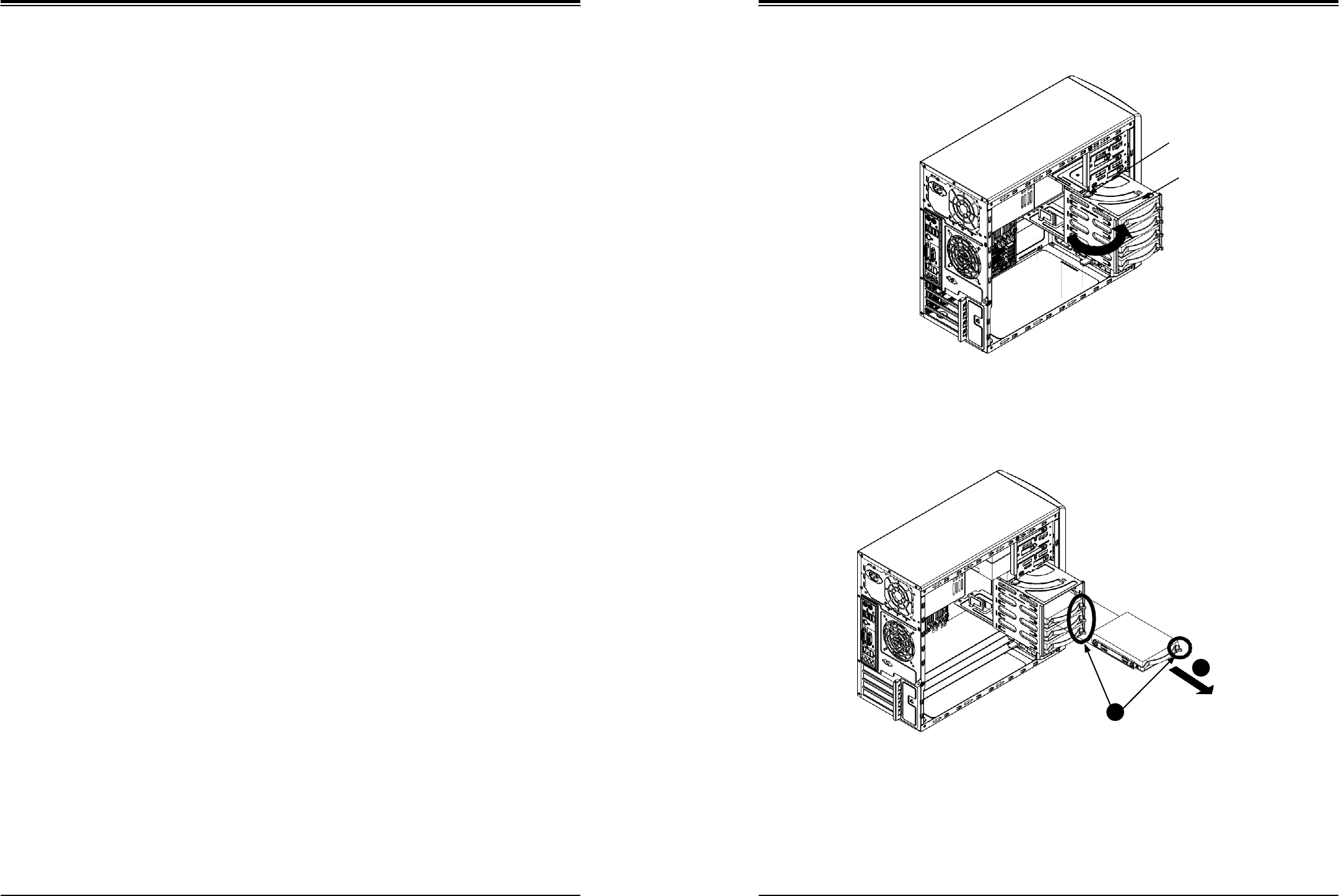
Hard Drives
Four fixed 3.5" SATA drives may be installed into the chassis. In order to access and install
components in the chassis, it is necessary to rotate the hard drive cage. Note that the 5039D-I
must be powered down before hard drives can be installed or removed
Installing a Hard Drive
Begin by removing power from the system as described in section 3.1 and remove the chassis
cover as described in section 3.2.
1. To rotate the hard drive cage, lift the release tab (A) as shown in Figure 3-11.
2. Rotate the hard disk drive cage (B) outward.
3. Press the release tab on the side of the hard drive carrier that is to be removed from the
hard drive cage as shown in Figure 3-12.
4. Gently slide the hard drive carrier out of the hard drive cage.
5. Insert a new hard drive into a hard drive tray by sliding it towards the back of the the
hard drive cage until it clicks into a locked position.
6. Connect the power and data cables to the hard drive.
7. Rotate the hard drive cage 90 degrees inward, returning it to the closed, operational
position in the chassis.
8. If desired, each hard drive may be further secured to the drive cage with an additional
(optional) screw at the middle of the drive.)
Release Tab (A)
HDD Cage (B)
Figure 3-11. Rotating the Hard Drive Cage
Figure 3-12. Installing Drives in the Chassis
3
2
Release Tabs
SuperWorkstation 5039D-I User's Manual
Chapter 3: Maintenance and Component Installation
28
29
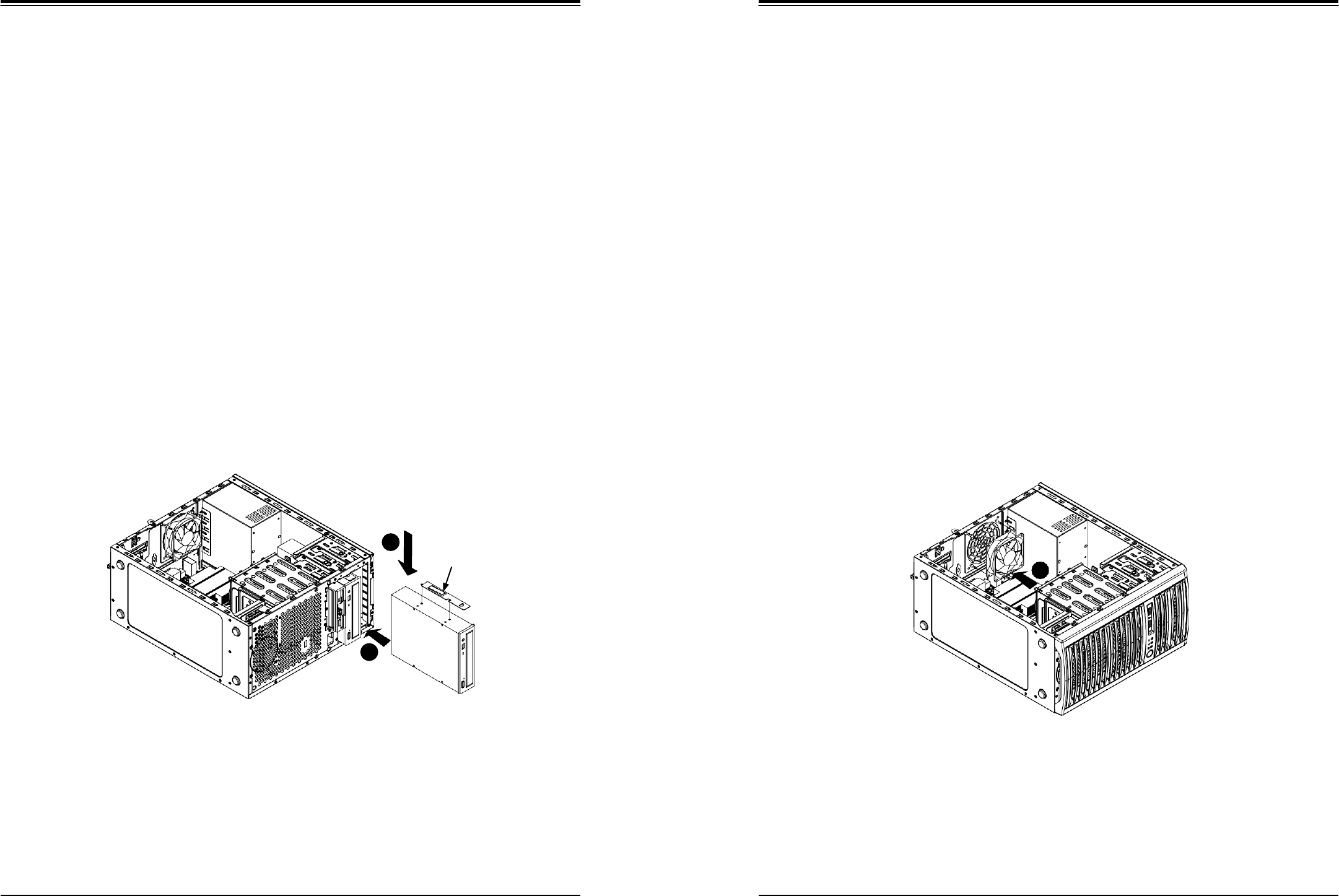
Optional Drive Bays
The SC731i-300B chassis has two empty 5.25" drive bays that support optional devices such
as a DVD-ROM.
Installing an Optional Device
Begin by removing power from the system as described in section 3.1.
1. Remove the front bezel from the chassis by lifting it upwards from the bottom and
pulling off the front of the chassis.
2. Remove the cover plate from the optical device slot on the front of the chassis.
3. Install the bracket rail (A) onto one side of the device by inserting the pins of the
bracket into the mounting holes on the side of the device.
4. Slide the device into the chassis.
5. If desired, screws may be used to secure the device into chassis.
6. Attach the power and data cables to the drive.
7. Replace the chassis cover before restoring power to the system.
System Cooling
The SC731i-300B includes a super quiet rear system fan that provides cooling for the chassis.
No tools or screws are required to install the system fan.
Under normal operation, the chassis fan and the power supply fan both run continuously. If
the chassis fan fails, the system must be powered down before replacing it. If the power
supply fan fails, the power supply itself must be replaced.
Replacing the System Fan
Begin by removing power from the system as described in section 3.1.
1. Remove the left chassis cover as described in section 3-2.
2. Insert the four rubber pins into the four mounting holes surrounding the fan grill on the
rear of the chassis.
3. Place the system fan on top of the fan grill, aligning the mounting holes of the fan grill
with the mounting holes of the system fan.
4. Pull the rubber pins through the mounting holes of the system fan to secure the fan to
the chassis.
Figure 3-13. Installing an Optional Device Figure 3-14. Replacing the System Fan
4
4
Bracket
Rail (A)
5

SuperWorkstation 5039D-I User's Manual
30
Power Supply
The T110 F4 chassis includes a 300-watt power supply. The power supply has the capability
to automatically sense and operate with an input voltage of 100 or 240V AC.
If it becomes necessary to replace the power supply, follow the instructions below.
Replacing the Power Supply
Begin by removing power from the system as described in section 3.1 and access the inside
of the system as described in section 3.2.
1. Remove the screws securing the power supply to the chassis. These are located on the
rear of the chassis. Set these screws aside for later use.
2. Gently lift the power supply out of the chassis.
3. Replace the failed power supply with an identical power supply model.
4. Secure the new power supply using the screws previously set aside.
5. Reconnect the power cables to the motherboard.
6. Plug the AC power cord back into the power module.
7. Finish by replacing the chassis left cover and then restoring power to the system.
SuperWorkstation 5039D-I User's Manual
Chapter 4: Motherboard Connections
31
32
Chapter 4
Motherboard Connections
This section describes the connections on the motherboard and provides pinout definitions.
Note that depending on how the system is configured, not all connections are required. The
LEDs on the motherboard are also described here. A severboard layout indicating component
locations may be found in Chapter 1.
Please review the Safety Precautions in Chapter 3 before installing or removing components.
4.1 Power Connections
One power connection on the X11SSL-F must be connected to the power supply.
•
24-pin Primary ATX Power (JPWR1)
Main ATX Power Connector
The primary power connector (JPWR1) meets the ATX SSI EPS 12V specification.
ATX Power 24-pin Connector
Pin Definitions
Pin#
Definition
Pin#
Definition
13
+3.3V
1
+3.3V
14
-12V
2
+3.3V
15
Ground
3
Ground
16
PS_ON
4
+5V
17
Ground
5
Ground
18
Ground
6
+5V
19
Ground
7
Ground
20
Res (NC)
8
PWR_OK
21
+5V
9
5VSB
22
+5V
10
+12V
23
+5V
11
+12V
24
Ground
12
+3.3V
Required Connection
4.2 Headers and Connectors
Fan Headers
There are five fan headers on the motherboard. These are 4-pin fan headers; pins 1-3 are
backward compatible with traditional 3-pin fans. The onboard fan speeds are controlled by
Thermal Management via IPMI. When using Thermal Management setting, please use all 3-
pin fans or all 4-pin fans.
Fan Header
Pin Definitions
Pin#
Definition
1
Ground (Black)
2
2.5A/+12V (Red)
3
Tachometer
4
PWM_Control
Standby Power
The +5V Standby Power Header On-LAN header is located at JSTBY1 on the motherboard.
You must have a card with a Standby Power connector and a cable to use this feature.
Wake-On-LAN
Pin Definitions
Pin#
Definition
1
+5V Standby
2
Ground
3
Wake-up
SuperWorkstation 5039D-I User's Manual
Chapter 4: Motherboard Connections
33
34
Power LED/Speaker
Pins 1-3 of JD1 are used for power LED indication and pins 4-7 are for the speaker. Please
note that the speaker connector pins (4-7) are used with an external speaker. If you wish to
use the onboard speaker, you should close pins 6-7 with a jumper.
TPM/Port 80 Header
A Trusted Platform Module (TPM)/Port 80 header is located at JTPM1 to provide TPM support
and Port 80 connection. Use this header to enhance system performance and data security.
SGPIO Headers
The SGPIO (Serial General Purpose Input/Output) headers are used to communicate with
the enclosure management chip on the backplane and support the SATA ports.
Internal Speaker/Buzzer
The Internal Speaker (SP1) can be used to provide audible notifications using various beep
codes.
NC = No Connection
Disk-On-Module Power Connector
Two power connectors for SATA DOM (Disk_On_Module) devices are located at JSD1/JSD2.
Connect appropriate cables here to provide power support for your Serial Link DOM devices.
Power SMB (I2C) Header
The Power System Management Bus (I2C) connector (JPI2C1) monitors the power supply,
fan, and system temperatures.
Power SMB Header
Pin Definitions
Pin#
Definition
1
Clock
2
Data
3
PMBUS_Alert
4
Ground
5
+3.3V
Speaker Connector
Pin Definitions
Pin#
Definition
4
P5V
5
Key
6
R_SPKPIN_N
7
R_SPKPIN
PWR LED Connector
Pin Definitions
Pin#
Definition
1
JD1_PIN1
2
FP_PWR_LED
3
FP_PWR_LED
Trusted Platform Module Header
Pin Definitions
Pin#
Definition
Pin#
Definition
1
LCLK
2
GND
3
LFRAME#
4
<(KEY)>
5
LRESET#
6
+5V
7
LAD3
8
LAD2
9
+3.3V
10
LAD1
11
LAD0
12
GND
13
SMB_CLK
14
SMB_DAT
15
+3V Stdby
16
SERIRQ
17
GND
18
CLKRUN#
19
LPCPD#
20
LDRQ#
I-SGPIO 1/2
I-SGPIO1
SATA Ports 0-3
I-SGPIO2
SATA Ports 4-7
SGPIO Header
Pin Definitions
Pin#
Definition
Pin#
Definition
1
NC
2
NC
3
GND
4
Data
5
Load
6
GND
7
Clock
8
NC
Internal Buzzer
Pin Definitions
Pin#
Polarity
Definition
1
Pos (+)
Beep In
2
Neg (-)
Alarm Speaker
DOM Power
Pin Definitions
Pin#
Definition
1
5V
2
Ground
3
Ground
SuperWorkstation 5039D-I User's Manual
Chapter 4: Motherboard Connections
35
36
4-pin BMC External I2C Header
A System Management Bus header for IPMI 2.0 is located at JIPMB1. Connect the appropriate
cable here to use the IPMB I2C connection on your system.
Unit Identifier Switch/UID LED Indicator
A rear Unit Identifier (UID) switch and a rear UID LED (LED1) are located next to the VGA
port on the motherboard. The front UID switch and the front UID LED are both located on the
Front Panel Control (JF1) (with the front UID switch on pin 13, and the front LED on pin 7
of JF1). When you press the front or the rear UID switch, both front and rear UID LEDs will
be turned on. Press the UID switch again to turn off the LED indicators. The UID Indicators
provide easy identification of a system unit that may be in need of service.
Note: UID can also be triggered via IPMI on the motherboard. For more information on IPMI,
please refer to the IPMI User's Guide posted on our website at http://www.supermicro.com.
Overheat/Fan Fail LED Header
The JOH1 header is used to connect an LED indicator to provide warnings of chassis
overheating and fan failure. This LED will blink when a fan failure occurs.
Chassis Intrusion
A Chassis Intrusion header is located at JL1 on the motherboard. Attach the appropriate cable
from the chassis to inform you of a chassis intrusion when the chassis is opened.
Chassis Intrusion
Pin Definitions
Pin#
Definition
1
Intrusion Input
2
Ground
Overheat LED Header
Status
State
Definition
Solid
Overheat
Blinking
Fan Fail
Overheat LED
Pin Definitions
Pin#
Definition
1
5vDC
2
OH Active
External I2C Header
Pin Definitions
Pin#
Definition
1
Data
2
GND
3
Clock
4
NC
UID Switch
Pin Definitions
Pin#
Definition
1
Ground
2
Ground
3
Button In
4
Ground
UID LED
Pin Definitions
Color
Status
Blue: On
Unit Identified
SuperWorkstation 5039D-I User's Manual
Chapter 4: Motherboard Connections
37
38
Control Panel
JF1 contains header pins for various control panel connections. See the figure below for the
pin locations and definitions of the control panel buttons and LED indicators.
All JF1 wires have been bundled into a single cable to simplify this connection. Make sure
the red wire plugs into pin 1 as marked on the motherboard. The other end connects to the
control panel PCB board.
Reset Button
The Reset Button connection is located on pins 3 and 4 of JF1. Attach it to a hardware reset
switch on the computer case.
1
Power Button PWR
Reset Button Reset
P3V3
2
Ground
Ground
Power Fail LED
Power Fail LED
The Power Fail LED connection is located on pins 5 and 6 of JF1.
UID LED OH/Fan Fail LED
P3V3_STBY
P3V3_STBY
P3V3_STBY/ID_UID_SW
P3V3
NC
NIC2 Link Active LED
NIC1 Link Active LED
HDD LED
FP PWRLED
NC
SW_NMI_N
19 20
Ground
Overheat (OH)/Fan Fail
Figure 4-1. JF1: Control Panel Pins Connect an LED cable to pins 7 and 8 of JF1 to use the Overheat/Fan Fail LED connections.
The LED on pin 8 provides warnings of overheat or fan failure.
Power Button
The Power Button connection is located on pins 1 and 2 of JF1. Momentarily contacting both
pins will power on/off the system. This button can also be configured to function as a suspend
button (with a setting in the BIOS - see Chapter 7). To turn off the power when the system
is in suspend mode, press the button for 4 seconds or longer.
Power Button
Pin Definitions (JF1)
Pin#
Definition
1
Signal
2
Ground
Reset Button
Pin Definitions (JF1)
Pin#
Definition
3
Reset
4
Ground
Power Fail LED
Pin Definitions (JF1)
Pin#
Definition
5
3.3V
6
PWR Supply Fail
OH/Fan Fail Indicator
Status
Status
Definition
Off
Normal
On
Overheat
Flashing
Fan Fail
OH/Fan Fail LED
Pin Definitions (JF1)
Pin#
Definition
7
Blue LED
8
OH/Fan Fail LED

SuperWorkstation 5039D-I User's Manual
Chapter 4: Motherboard Connections
39
40
NIC1/NIC2 (LAN1/LAN2)
The NIC (Network Interface Controller) LED connection for LAN port 1 is located on pins 11
and 12 of JF1, and the LED connection for LAN Port 2 is on Pins 9 and 10. Attach the NIC
LED cables here to display network activity.
LAN1/LAN2 LED
Pin Definitions (JF1)
Pin#
Definition
9
NIC2 Activity LED
10
NIC2 Link LED
11
NIC1 Activity LED
12
NIC1 Link LED
HDD LED/UID Switch
The HDD LED/UID Switch connection is located on pins 13 and 14 of JF1. Attach a cable to
Pin 14 to show hard drive activity status. Attach a cable to Pin 13 to use UID switch. Refer
to the table below for pin definitions.
NMI Button
The non-maskable interrupt button header is located on pins 19 and 20 of JF1.
NMI Button
Pin Definitions (JF1)
Pin#
Definition
19
Control
20
Ground
Data Cables
The data cables in the system have been carefully routed to maintain airflow efficiency. If
you disconnect any of these cables, take care to re-route them as they were originally when
reconnecting them.
Important! Make sure the the cables do not come into contact with the fans.
HDD LED
Pin Definitions (JF1)
Pin#
Definition
13
3.3V Standby/UID Switch
14
HDD Active
Power LED
The Power LED connection is located on pins 15 and 16 of JF1.
Power LED
Pin Definitions (JF1)
Pin#
Definition
15
3.3V
16
Power LED
SuperWorkstation 5039D-I User's Manual
Chapter 4: Motherboard Connections
41
42
4.3 Ports
Serial Ports
One COM port (COM1) is located on the rear I/O panel.
SATA Ports
The X11SSL-F includes a total of six SATA ports, supported by the Intel C232 PCH chip.
These SATA ports support RAID 0, 1, 5, and 10.
Notes: I-SATA0 and I-SATA1 are Supermicro SuperDOMs. These are yellow SATADOM ports
with power pins built in and do not require separate external power cables. These ports are
backward-compatible with non-Supermicro SATADOMs that do require external power.
Universal Serial Bus (USB) Ports
There are two USB 2.0 ports (USB 0/1) and two USB 3.0 ports (USB 6/7) located on the rear
I/O panel. The X11SSL-F also has two front access USB 2.0 headers (USB2/3 and USB4/5)
and one front access USB 3.0 header (USB8/9). USB10 is a Type A 3.0 header. The onboard
headers can be used to provide front side USB access with a cable (not included).
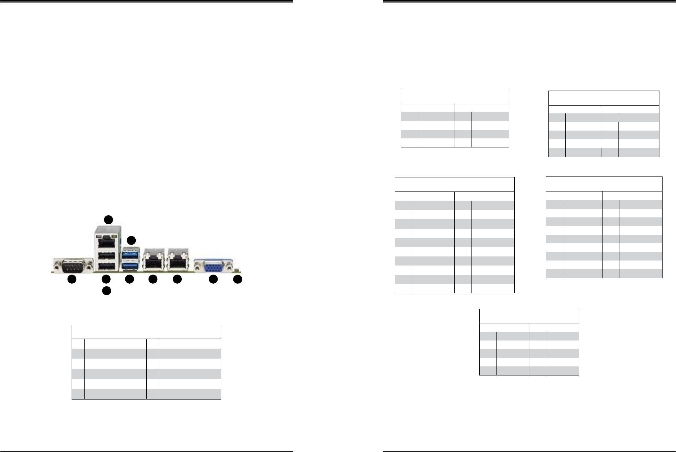
Rear I/O Ports
See the figure below for the locations and descriptions of the various I/O ports on the rear
of the motherboard.
Figure 4-2. Rear I/O Ports
4
Rear I/O Ports
#
Description
#
Description
1.
COM1 Port
6.
USB6 (3.0)
2.
IPMI LAN
7.
LAN1
3
USB1
8
LAN2
4
USB0
9
VGA Port
5.
USB7 (3.0)
10
UID Switch
Type A USB 10 (USB 3.0)
Pin Definitions
Pin# Definition
Pin# Definition
1
VBUS
5
SSRX-
2
USB_N
6
SSRX+
3
USB_P
7
GND
4
Ground
8
SSTX-
9
SSTX+
2
5
1
3
6
7
8
9
10
Back Panel USB 0/1 (USB 2.0)
Pin Definitions
Pin#
Definition
Pin#
Definition
1
+5V
5
+5V
2
USB_N
6
USB_N
3
USB_P
7
USB_P
4
Ground
8
Ground
Front Panel USB 2/3, 4/5 (USB 2.0)
Pin Definitions
Pin#
Definition
Pin#
Definition
1
+5V
2
+5V
3
USB_N
4
USB_N
5
USB_P
6
USB_P
7
Ground
8
Ground
9
Key
10
NC
Back Panel USB 6/7 (USB 3.0)
Pin Definitions
Pin#
Definition
Pin#
Definition
1
VBUS
19
Power
2
Stda_SSRX-
18
USB3_RN
3
Stda_SSRX+
17
USB3_RP
4
GND
16
GND
5
Stda_SSTX-
15
USB3_TN
6
Stda_SSTX+
14
USB3_TP
7
GND
13
GND
8
D-
12
USB_N
9
D+
11
USB_P
10
Front Panel USB 8/9 (USB 3.0)
Pin Definitions
Pin#
Definition
Pin#
Definition
A1
VBUS
B1
Power
A2
D-
B2
USB_N
A3
D+
B3
USB_P
A4
GND
B4
GND
A5
Stda_SSRX-
B5
USB3_RN
A6
Stda_SSRX+
B6
USB3_RP
A7
GND
B7
GND
A8
Stda_SSTX-
B8
USB3_TN
A9
Stda_SSTX+
B9
USB3_TP
SuperWorkstation 5039D-I User's Manual
Chapter 4: Motherboard Connections
43
44
VGA Port
A video (VGA) port is located next to LAN2 on the I/O back panel.
LAN Ports
Two Gigabit Ethernet ports (LAN1 and LAN2) are located on the rear I/O panel of the
motherboard. In addition, a dedicated IPMI LAN port is located above the USB 0/1 ports. All
of these ports accept RJ45 cables. Please refer to the LED Indicator section for LAN LED
information.
4.4 Jumpers
Explanation of Jumpers
To modify the operation of the motherboard, jumpers are used to choose between optional
settings. Jumpers create shorts between two pins to change the function associated with it.
Pin 1 is identified with a square solder pad on the printed circuit board. See the motherboard
layout page for jumper locations.
Note: On a two-pin jumper, "Closed" means the jumper is on both pins and "Open" indicates
the jumper is either on only one pin or has been completely removed.
CMOS Clear
JBT1 is used to clear CMOS, which will also clear any passwords. Instead of pins, this jumper
consists of contact pads to prevent accidentally clearing the contents of CMOS.
To Clear CMOS
1. First power down the system and unplug the power cord(s).
2. Remove the cover of the chassis to access the motherboard.
3. Remove the onboard battery from the motherboard.
4. Short the CMOS pads with a metal object such as a small screwdriver for at least four
seconds.
5. Remove the screwdriver (or shorting device).
6. Replace the cover, reconnect the power cord(s) and power on the system.
Notes: Clearing CMOS will also clear all passwords.
Do not use the PW_ON connector to clear CMOS.
JBT1 contact pads
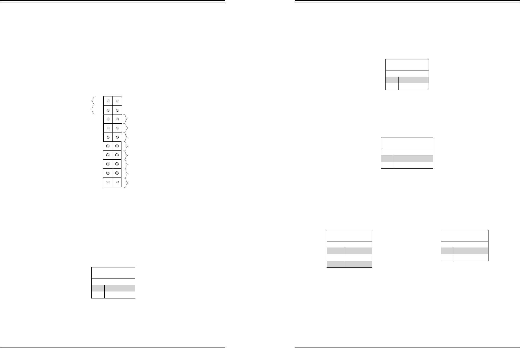
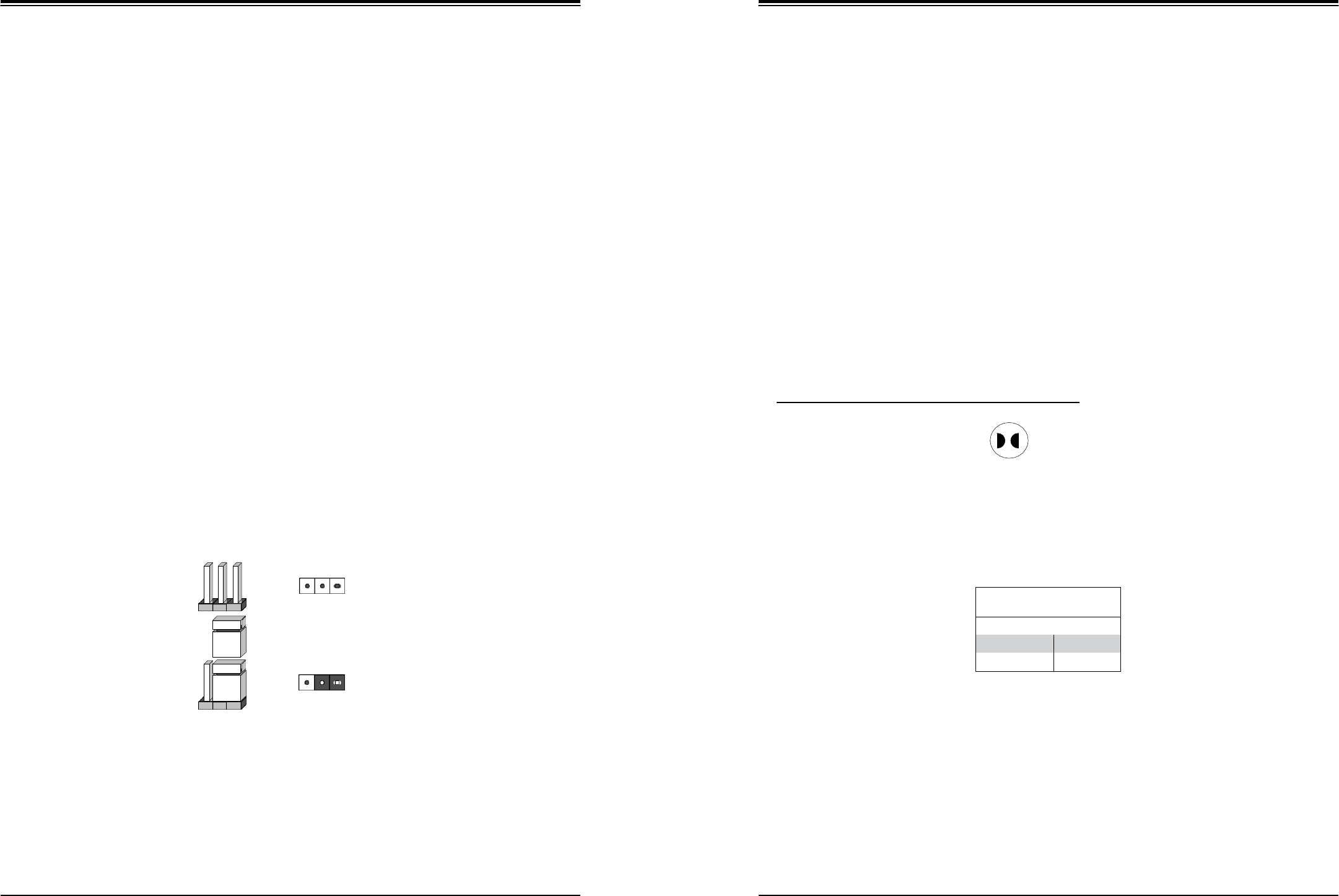
VGA Enable/Disable
JPG1 allows you to enable or disable the VGA port. The default setting is Enabled.
Connector
Pins
Jumper
Setting
3 2 1
3 2 1
VGA Enable/Disable
Jumper Settings
Jumper Setting
Definition
Pins 1-2
Enabled
Pins 2-3
Disabled
SuperWorkstation 5039D-I User's Manual
Chapter 4: Motherboard Connections
45
46
LAN1/2 Enable/Disable
Change the setting of jumper JPL1 and JPL2 to enable or disable the LAN1 and LAN2
Ethernets ports, respectively. The default setting is Enabled.
BIOS Recovery
Use jumper JBR1 to recover the BIOS settings on the motherboard. The default setting is
Normal.
Watch Dog
JWD controls the Watch Dog function. Watch Dog is a monitor that can reboot the system
when a software application hangs. Jumping pins 1-2 will cause Watch Dog to reset the system
if an application hangs. Jumping pins 2-3 will generate a non-maskable interrupt signal for the
application that hangs. Watch Dog must also be enabled in BIOS. The default setting is Reset.
Note: When Watch Dog is enabled, the user needs to write their own application software
to disable it.
SMBus to PCI Slots Enable/Disable
Use jumpers JI2C1 and JI2C2 to connect the System Management Bus (I2C) to the PCI-
Express slots to improve PCI performance. These two jumpers should be set to the same
setting. The default setting is Enabled.
Manufacturer Mode Select
Close pins 2 and 3 of jumper JPME2 to bypass SPI flash security and force the system to
operate in the manufacturer mode, which will allow the user to flash the system firmware from
a host server for system setting modifications. The default setting is Normal.
BMC Enable/Disable
Jumper JPB1 allows you to enable the embedded ASpeed AST2400 Baseboard Management
Controller (BMC) to provide IPMI 2.0/KVM support on the motherboard. The default setting
is Enabled.
Manufacturer Mode
Jumper Settings
Jumper Setting
Definition
Pins 1-2
Normal
Pins 2-3
Manufacturer Mode
BIOS Recovery
Jumper Settings
Jumper Setting
Definition
Pins 1-2
Normal
Pins 2-3
BIOS Recovery
LAN1/2 Enable/Disable
Jumper Settings
Jumper Setting
Definition
Pins 1-2
Enabled
Pins 2-3
Disabled
I2C for PCI-E Slots
Jumper Settings
Jumper Setting
Definition
Pins 1-2
Enabled
Pins 2-3
Disabled
Watch Dog
Jumper Settings
Jumper Setting
Definition
Pins 1-2
Reset
Pins 2-3
NMI
Open
Disabled
BMC Enable
Jumper Settings
Jumper Setting
Definition
Pins 1-2
Enabled
Pins 2-3
Disabled
SuperWorkstation 5039D-I User's Manual
Chapter 4: Motherboard Connections
47
48
4.5 LED Indicators
LAN LEDs
Two LAN ports are located on the rear I/O panel of the motherboard. Each Ethernet LAN
port has two LEDs. The green LED indicates activity, while the other Link LED may be green,
amber, or off to indicate the speed of the connection.
BMC Heartbeat LED
A BMC Heartbeat LED is located at LEDBMC on the motherboard. When LEDBMC is blinking,
the BMC is functioning normally.
Onboard Power LED
The Onboard Power LED is located at LEDPWR. When this LED is on, the system is on.
Be sure to turn off the system and unplug the power cord before removing or installing
components.
Dedicated IPMI LAN LEDs
An IPMI LAN is also located on the rear I/O panel. The LED on the right indicates activity,
while the LED on the left indicates the speed of the connection.
IPMI LAN LEDs
LED
Color/State
Definition
Link (left)
Green: Solid
Amber: Solid
100 Mbps
1Gbps
Activity (Right)
Amber: Blinking
Active
Onboard Power LED Indicator
LED Color
Definition
Green:
Blinking
BMC: Normal
LAN1-4 Activity LED (Right)
LED State
Color
Status
Definition
Green
Flashing
Active
LAN1-4 Link LED (Left)
LED State
LED Color
Definition
Off
No Connection/10 Mbps
Amber
1 Gbps
Green
100 Mbps
Onboard Power LED Indicator
LED Color
Definition
Off
System Off
(power cable not
connected)
Green
System On
SuperWorkstation 5039D-I User's Manual
Chapter 5: Software
49
50
Chapter 5
Software
After the hardware has been installed, you should install the Operating System (OS), configure
RAID settings and install the drivers. Necessary drivers and utilities may be found at
resource CD
5.1 OS Installation
You must first configure RAID settings (if using RAID) before you install the Windows OS and
the software drivers. To configure RAID settings, please refer to the installation guide.
Installing the Windows OS for a RAID System
1. Insert Microsoft's Windows Setup DVD in the DVD drive and the system will start
booting up from the DVD.
2. Insert the USB stick containing Windows drivers to a USB port on the system.
Note: for older legacy OS's, please use a method to slipstream the drivers.
3. Select the partition on the drive in which to install Windows.
4. Browse the USB folder for the proper driver files.
5. Choose the RAID driver indicated in the Windows OS Setup screen, then choose the
hard drive in which you want to install it.
6. Once all devices are specified, continue with the installation.
7. After the Windows OS installation is completed, the system will automatically reboot.
Installing Windows to a Non-RAID System
1. Insert Microsoft's Windows OS Setup DVD in the DVD-ROM drive and the system will
start booting up from the DVD.
2. Continue with the installation. The Windows OS Setup screen will display.
3. From the Windows OS Setup screen, press the <Enter> key. The OS Setup will
automatically load all device files and then continue with the Windows installation.
4. After the installation has completed, the system will automatically reboot.
5.2 Driver Installation
The Supermicro FTP site contains drivers and utilities for your system at ftp://ftp.supermicro.
com. Some of these must be installed, such as the chipset driver.
After accessing the FTP site, go into the CDR_Images directory and locate the ISO file for
your motherboard. Download this file to create a DVD of the drivers and utilities it contains.
(You may also use a utility to extract the ISO file if preferred.)
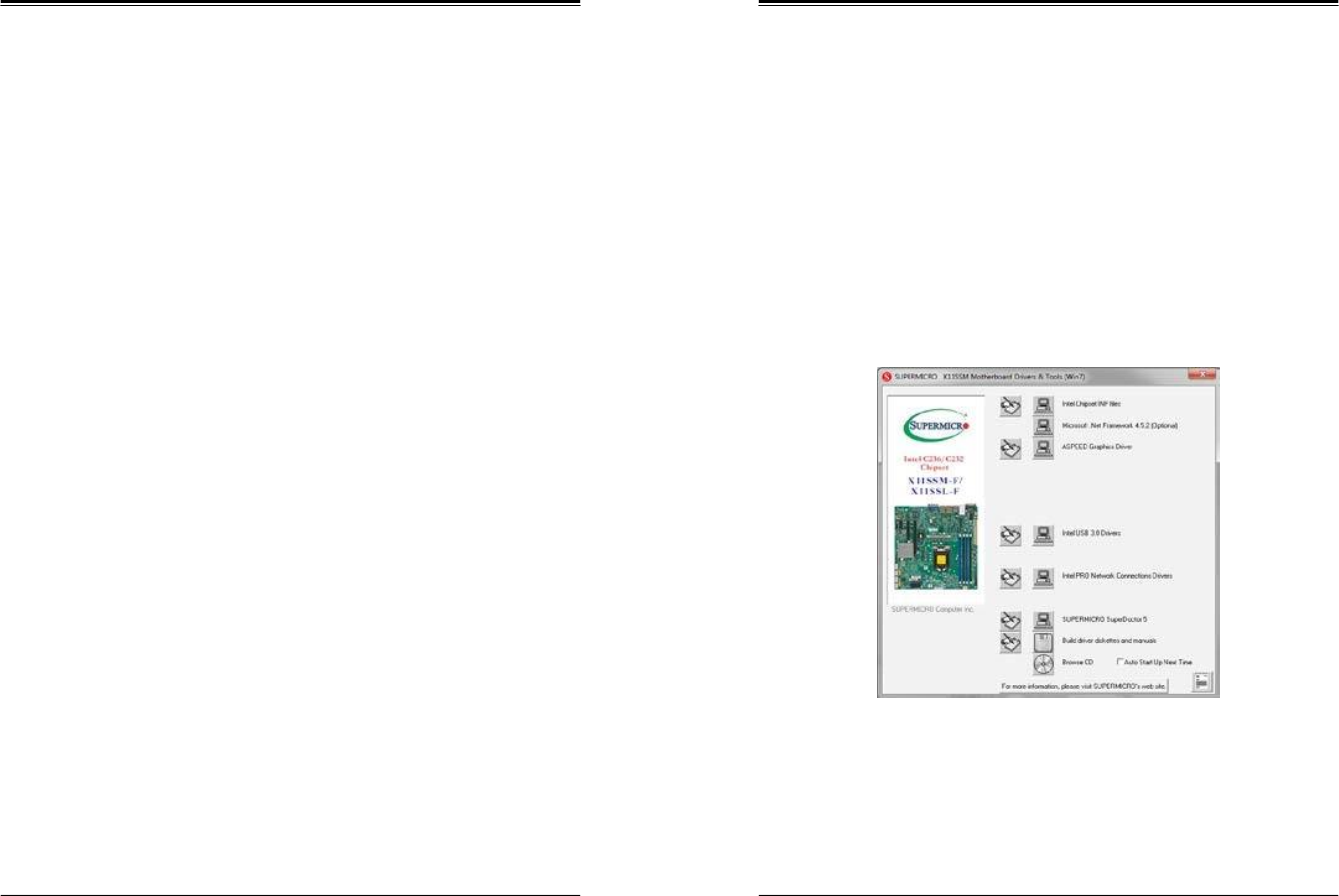
After creating a DVD with the ISO files, insert the disk into the DVD drive on your system
and the display shown in Figure 5-1 should appear.
Another option is to go to the Supermicro website at http://www.supermicro.com/products/.
Find the product page for your motherboard here, where you may download individual drivers
and utilities to your hard drive or a USB flash drive ans install from there.
Note: To install the Windows OS, please refer to the instructions posted on our website at
http://www.supermicro.com/support/manuals/.
Figure 5-1. Driver & Tool Installation Screen
Note: Click the icons showing a hand writing on paper to view the readme files for each
item. Click the computer icons to the right of these items to install each item (from top to the
bottom) one at a time. After installing each item, you must re-boot the system before
moving on to the next item on the list. The bottom icon with a CD on it allows you to view
the entire contents.
5.3 IPMI

SuperWorkstation 5039D-I User's Manual
Chapter 5: Software
51
52
The X11SSL-F support the Inteliigent Platform Management Interface (IPMI). IPMI is used
to provide remote access, monitoring and management. There are several BIOS settings
that are related to IPMI.
SuperWorkstation 5039D-I User's Manual
Chapter 6: BIOS
53
54
Chapter 6
BIOS
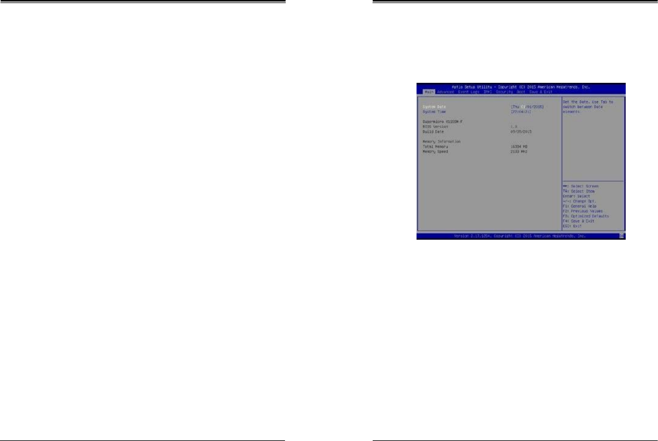
6.2 Main Setup
When you first enter the AMI BIOS setup utility, you will enter the Main setup screen. You can
always return to the Main setup screen by selecting the Main tab on the top of the screen.
The Main BIOS setup screen is shown below.The following Main menu items will be displayed:
6.1 Introduction
This chapter describes the AMIBIOS™ Setup utility for the X11SSL-F motherboard. The BIOS
is stored on a chip and can be easily upgraded using a flash program.
Note: Due to periodic changes to the BIOS, some settings may have been added
or deleted and might not yet be recorded in this manual. Please refer to the Manual
Download area of our website for any changes to BIOS that may not be reflected in
this manual.
Starting the Setup Utility
To enter the BIOS Setup Utility, hit the <Delete> key while the system is booting-up. (In
most cases, the <Delete> key is used to invoke the BIOS setup screen. There are a few
cases when other keys are used, such as <F1>, <F2>, etc.) Each main BIOS menu option
is described in this manual.
The Main BIOS screen has two main frames. The left frame displays all the options that can
be configured. “Grayed-out” options cannot be configured. The right frame displays the key
legend. Above the key legend is an area reserved for a text message. When an option is
selected in the left frame, it is highlighted in white. Often a text message will accompany it.
(Note that BIOS has default text messages built in. We retain the option to include, omit, or
change any of these text messages.) Settings printed in Bold are the default values.
A " " indicates a submenu. Highlighting such an item and pressing the <Enter> key will
open the list of settings within that submenu.
The BIOS setup utility uses a key-based navigation system called hot keys. Most of these
hot keys (<F1>, <F2>, <F3>, <Enter>, <ESC>, <Arrow> keys, etc.) can be used at any time
during the setup navigation process.
System Date/System Time
Use this option to change the system date and time. Highlight System Date or System Time
using the arrow keys. Enter new values using the keyboard. Press the <Tab> key or the arrow
keys to move between fields. The date must be entered in Day MM/DD/YYYY format. The
time is entered in HH:MM:SS format.
Note: The time is in the 24-hour format. For example, 5:30 P.M. appears as 17:30:00.
The date's default value is 01/01/2014 after RTC reset.
Supermicro X11SSL-F
BIOS Version
This item displays the version of the BIOS ROM used in the system.
Build Date
This item displays the date when the version of the BIOS ROM used in the system was built.
SuperWorkstation 5039D-I User's Manual
Chapter 6: BIOS
55
56
Memory Information
Total Memory
This item displays the total size of memory available in the system.
Memory Speed
This item displays the memory speed.
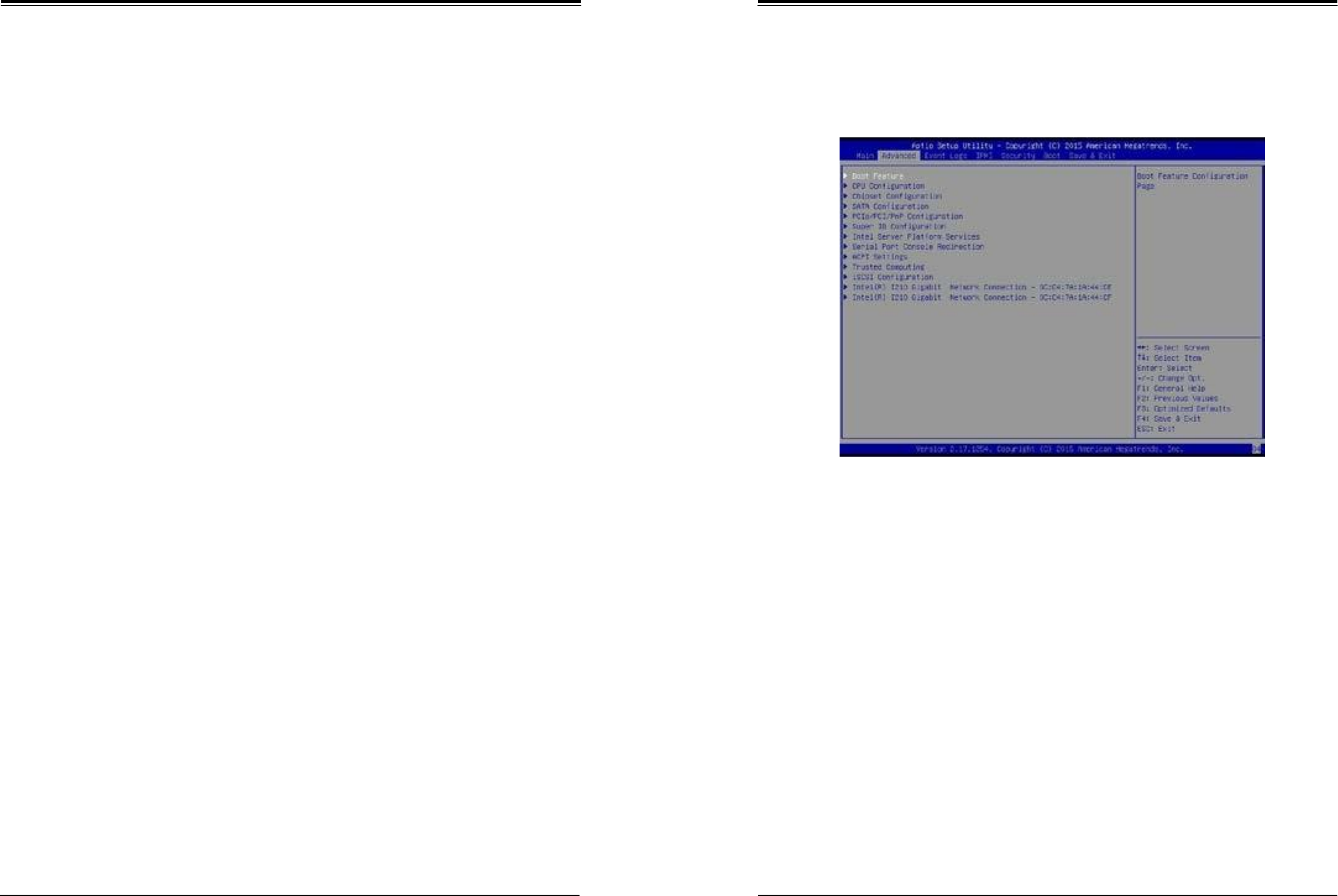
6.3
Advanced Setup Configurations
Use the arrow keys to select Boot Setup and press <Enter> to access the submenu items.
Warning: Take caution when changing the Advanced settings. An incorrect value, a very high
DRAM frequency, or an incorrect DRAM timing setting may make the system unstable. When
this occurs, revert to the default to the manufacture default settings.
Boot Feature
Quiet Boot
Use this feature to select the screen display between the POST messages and the OEM logo
upon bootup. Select Disabled to display the POST messages. Select Enabled to display the
OEM logo instead of the normal POST messages. The options are Enabled and Disabled.
AddOn ROM Display Mode
Use this feature to set the display mode for the Option ROM. Select Keep Current to display
the current AddOn ROM setting. Select Force BIOS to use the Option ROM display set by
the system BIOS. The options are Force BIOS and Keep Current.
Bootup NumLock State
Use this feature to set the Power-on state for the <Numlock> key. The options are Off and On.

SuperWorkstation 5039D-I User's Manual
Chapter 6: BIOS
57
58
Wait For 'F1' If Error
Use this feature to force the system to wait until the 'F1' key is pressed if an error occurs.
The options are Disabled and Enabled.
INT19 (Interrupt 19) Trap Response
Interrupt 19 is the software interrupt that handles the boot disk function. When this item is
set to Immediate, the ROM BIOS of the host adaptors will "capture" Interrupt 19 at bootup
immediately and allow the drives that are attached to these host adaptors to function as
bootable disks. If this item is set to Postponed, the ROM BIOS of the host adaptors will not
capture Interrupt 19 immediately and allow the drives attached to these adaptors to function
as bootable devices at bootup. The options are Immediate and Postponed.
Re-try Boot
If this item is enabled, the BIOS will automatically reboot the system from a specified boot
device after its initial boot failure. The options are Disabled, Legacy Boot, and EFI Boot.
Power Configuration
Watch Dog Function
If enabled, the Watch Dog Timer will allow the system to reset or generate NMI based on
jumper settings when it is expired for more than 5 minutes. The options are Enabled and
Disabled.
Power Button Function
This feature controls how the system shuts down when the power button is pressed. Select
4_Seconds_Override for the user to power off the system after pressing and holding the power
button for 4 seconds or longer. Select Instant Off to instantly power off the system as soon
as the user presses the power button. The options are 4 Seconds Override and Instant Off.
Restore on AC Power Loss
Use this feature to set the power state after a power outage. Select Stay-Off for
the system power to remain off after a power loss. Select Power-On for the system
power to be turned on after a power loss. Select Last State to allow the system
to resume its last power state before a power loss. The options are Power-On, Stay-
Off, and Last State.
CPU Configuration
The following CPU information will display:
•
CPU Signature
•
Microcode Patch
•
Max CPU Speed
•
Min CPU Speed
•
CPU Speed
•
Processor Cores
•
Hyper Threading Technology
•
Intel VT-x Technology
•
Intel SMX Technology
•
64-bit
•
EIST Technology
•
CPU C3 State
•
CPU C6 State
•
CPU C7 State
•
L1 Data Cache
•
L1 Code Cache
•
L2 Cache
•
L3 Cache
•
L4 Cache
Hyper-threading (Available when supported by the CPU)
Select Enabled to support Intel Hyper-threading Technology to enhance CPU performance.
The options are Enabled and Disabled.

SuperWorkstation 5039D-I User's Manual
Chapter 6: BIOS
59
60
Active Processor Cores
This feature determines how many CPU cores will be activated for each CPU. When all
is selected, all cores in the CPU will be activated. (Please refer to Intel's website for more
information.) The options are All and 1, 2, and 3.
Intel®
Virtualization Technology
Select Enable to use Intel Virtualization Technology so that I/O device assignments will be
reported directly to the VMM (Virtual Memory Management) through the DMAR ACPI Tables.
This feature offers fully-protected I/O resource-sharing across the Intel platforms, providing
the user with greater reliability, security and availability in networking and data-sharing. The
options are Enabled and Disabled.
Hardware Prefetcher (Available when supported by the CPU)
If set to Enabled, the hardware prefetcher will prefetch streams of data and instructions from
the main memory to the L2 cache to improve CPU performance. The options are Disabled
and Enabled.
Adjacent Cache Line Prefetch (Available when supported by the CPU)
The CPU prefetches the cache line for 64 bytes if this feature is set to Disabled. The CPU
prefetches both cache lines for 128 bytes as comprised if this feature is set to Enabled.
CPU AES
Select Enabled to enable Intel CPU Advanced Encryption Standard (AES) Instructions for
CPU to enhance data integrity. The options are Enabled and Disabled.
Boot Performance Mode
This feature allows the user to select the performance state that the BIOS will set before the
operating system handoff. The options are Power Saving, Max Non-Turbo Performance
and Turbo Performance.
HardWare P-States (HWP)
Use this feature to enable or disable hardware P-States support. The options are Disabled
and Enabled.
Intel®
SpeedStep™
Intel SpeedStep Technology allows the system to automatically adjust processor voltage and
core frequency to reduce power consumption and heat dissipation. The options are Disabled
and Enabled.
Turbo Mode
Select Enabled for processor cores to run faster than the frequency specified by the
manufacturer. The options are Disabled and Enabled.
Package Power Limit MSR Lock
Select Enabled to lock the package power limit for the model specific registers. The options
are Disabled and Enabled.
Power Limit 1 Override
Select Enabled to support average power limit (PL1) override. The default setting is Disabled.
Power Limit 2 Override
Select Enabled to support rapid power limit (PL2) override. The default setting is Enabled.
Power Limit 2
Use this item to configure the value for Power Limit 2. The value is in milli watts and the step
size is 125mW. Use the number keys on your keyboard to enter the value. Enter 0 to use the
manufacture default setting If the value is 0, the BIOS will set PL2 as 1.25* TDP.
1- Core Ratio Limit Override
This increases (multiplies) 1 clock speed in the CPU core in relation to the bus speed when
one CPU core is active. Press "+" or "-" on your keyboard to change the value. Enter 0 to
use the manufacture default setting.
2- Core Ratio Limit Override
This increases (multiplies) 2 clock speeds in the CPU core in relation to the bus speed when
two CPU cores are active. Press "+" or "-" on your keyboard to change the value. Enter 0 to
use the manufacture default setting.
3- Core Ratio Limit Override
This increases (multiplies) 3 clock speeds in the CPU core in relation to the bus speed when
three CPU cores are active. Press "+" or "-" on your keyboard to change the value. Enter 0
to use the manufacture default setting.
4- Core Ratio Limit Override
This increases (multiplies) 4 clock speeds in the CPU core in relation to the bus speed when
three CPU cores are active. Press "+" or "-" on your keyboard to change the value. Enter 0
to use the manufacture default setting.
CPU C-States
Use this feature to enable the C-State of the CPU. The options are Disabled and Enabled.
Enhanced C-States
Use this feature to enable the enhanced C-State of the CPU. The options are Disabled and
Enabled.

SuperWorkstation 5039D-I User's Manual
Chapter 6: BIOS
61
62
C-State Auto Demotion
Use this feature to prevent unnecessary excursions into the C-states to improve latency. The
options are Disabled, C1, C3, and C1 and C3.
C-State Un-Demotion
This feature allows the user to enable or disable the un-demotion of C-State. The options are
Disabled, C1, C3, and C1 and C3
Package C-State Demotion
Use this feature to enable or disable the Package C-State demotion. The options are Disabled
and Enabled.
Package C-State Un-Demotion
Use this feature to enable or disable the Package C-State un-demotion. The options are
Disabled and Enabled.
C-S tate Pre-Wake
This feature allows the user to enable or disable the C-State Pre-Wake. The options are
Disabled and Enabled.
Package C-State Limit
Use this feature to set the Package C-State limit. The options are C0/C1, C2, C3, C6, C7,
C7s, C8, and AUTO.
CPU Thermal Configuration
CPU DTS
Select Enabled for the ACPI thermal management to use the DTS SMM mechanism to
obtain CPU temperature values. Select Disabled for EC to report the CPU temperature
values. The options are Disabled and Enabled.
ACPI 3.0 T-States
Select Enabled to support CPU throttling by the operating system to reduce power
consumption. The options are Enabled and Disabled.
Chipset Configuration
Warning: Setting the wrong values in the following features may cause the system to malfunc-
tion.
System Agent (SA) Configuration
The following System Agent information will display:
•
System Agent Bridge Name
•
SA PCIe Code Version
•
VT-d
VT-d
Select Enabled to enable Intel Virtualization Technology support for Direct I/O VT-d by
reporting the I/O device assignments to VMM through the DMAR ACPI Tables. This feature
offers fully-protected I/O resource-sharing across the Intel platforms, providing the user with
greater reliability, security and availability in networking and data-sharing. The options are
Enabled and Disabled.
Gaussian Mixture Model
This feature is to enable or disable the System Agent Gaussian Mixture Model device. The
opitons are Enabled and Disabled.
Graphics Configuration
Primary Display
Use this feature to select the graphics device to be used as the primary display. The options
are Auto, PEG, and PCIE.
Primary PEG
This feature allows the user to select the primary PCI Express Graphics (PEG) slot. The
options are CPU SLOT6 PCI-E 3.0 X8 (IN X16) and CPU SLOT7 PCI-E 3.0 X8.
Primary PCIE (PCI-Express Graphics)
This feature allows the user to specify which graphics card to be used as the primary
graphics card. The options are Onboard, PCH SLOT4 PCI-E 3.0 X4 (IN X8), and PCH
SLOT5 PCI-E 3.0 X4 (IN X8).

SuperWorkstation 5039D-I User's Manual
Chapter 6: BIOS
63
64
DMI/OPI Configuration
The following DMI information will display:
•
DMI
DMI VC1 Control
Use this feature to enable or disable DMI Virtual Channel 1. The options are Enabled and
Disabled.
DMI VCm Control
Use this feature to enable or disable the DMI Virtual Channel map. The options are Enabled
and Disabled.
DMI Link ASPM Control
Use this feature to set the ASPM (Active State Power Management) state on the SA (System
Agent) side of the DMI Link. The options are Disabled and L1.
DMI Extended Sync Control
Use this feature to enable or disable the DMI extended synchronization. The options are
Enabled and Disabled.
DMI De-Emphasis Control
Use this feature to configure the De-emphasis control on DMI. The options are -6dB and
-3.5dB.
PEG Port Configuration
CPU SLOT6 PCI-E 3.0 X8 (IN X16)
SLOT6 Max Link Speed
Use this item to configure the link speed of a PCI-E port specified by the user. The options
are Auto, Gen1, Gen2, and Gen3.
SLOT6 Max Payload Size
Select Auto for the system BIOS to automatically set the maximum payload value for a PCI-E
device to enhance system performance. The options are Auto, 128 TLP, and 256 TLP.
SLOT6 Slot Power Limit Value
Use this feature to set the upper limit on the power supplied by the PCIE slot. Press "+"
or "-" on your keyboard to change this value. The default setting is 75.
SLOT6 Slot Power Limit Scale
Use this feature to select the scale used for the slot power limit value. The options are
1.0x, 0.1x, 0.01x, and 0.001x.
CPU SLOT7 PCI-E 3.0 X8
SLOT7 Max Link Speed
Use this item to configure the link speed of a PCI-E port specified by the user. The options
are Auto, Gen1, Gen2, and Gen3.
SLOT7 Max Payload Size
Select Auto for the system BIOS to automatically set the maximum payload value for a PCI-E
device to enhance system performance. The options are Auto, 128 TLP, and 256 TLP.
SLOT7 Slot Power Limit Value
Use this feature to set the upper limit on the power supplied by the PCIE slot. Press "+"
or "-" on your keyboard to change this value. The default setting is 75.
SLOT7 Slot Power Limit Scale
Use this feature to select the scale used for the slot power limit value. The options are
1.0x, 0.1x, 0.01x, and 0.001x.
Program PCIe ASPM After OPROM
PCIe ASPM, the Active State Power Management for PCI-Express slots, is a power
management protocol used to manage power consumption of serial-link devices installed
on PCI-Exp slots during a prolonged off-peak time. If this item is set to Enabled, PCI-E
ASMP will be programmed after OPROM. If this item is set to Disabled, the PCI-E ASPM
will be programmed before OPROM. The options are Disabled and Enabled.
Memory Configuration
The following memory information will display:
•
Memory RC Version
•
Memory Frequency
•
Total Memory
•
VDD
•
DIMMA1
•
DIMMA2
•
DIMMB1
•
DIMMB2
•
Memory Timings (tCL-tRCD-tRP-tRAS)

SuperWorkstation 5039D-I User's Manual
Chapter 6: BIOS
65
66
Maximum Memory Frequency
Use this feature to set the maximum memory frequency for onboard memory modules. The
options are Auto, 1067, 1200, 1333, 1400, 1600, 1800, 1867, 2000, 2133, 2200, and 2400.
Max TOLUD
This feature sets the maximum TOLUD value, which specifies the "Top of Low Usable
DRAM" memory space to be used by internal graphics devices, GTT Stolen Memory, and
TSEG, respectively, if these devices are enabled. The options are Dynamic, 1 GB, 1.25
GB, 1.5 GB, 1.75 GB, 2 GB, 2.25 GB, 2.5 GB, 2.75 GB, 3 GB, 3.25 GB, and 3.5 GB.
Energy Performance Gain
Use this feature to enable or disable the energy performance gain. The options are Disabled
and Enabled.
Memory Scrambler
Select Enabled to enable memory scrambler support. The options are Disabled and
Enabled.
Fast Boot
Use this feature to enable or disable fast path through the memory reference code. The
options are Enabled and Disabled.
REFRESH_2X_MODE
Use this feature to select the refresh mode. The options are Disabled, 1-Enabled for WARM
or HOT, and 2-Enabled HOT only.
Closed Loop Thermal Management
Use this feature to monitor the power consumption and temperature of the system to predict
a thermal trend. The options are Disabled and Enabled.
PCH-IO Configuration
The following PCH-IO information will display:
•
Intel PCH RC Version
•
Intel PCH SKU Name
•
Intel PCH Rev ID
PCI Express Configuration
DMI Link ASPM Control
Use this feature to set the ASPM (Active State Power Management) state on the SA (System
Agent) side of the DMI Link. The options are Disabled and Enabled.
Peer Memory Write Enable
Use this feature to enable or disable peer memory write. The options are Disabled or
Enabled.
PCH SLOT4 PCI-E 3.0 X4 (IN X8)
SLOT4 ASPM
Use this item to set the Active State Power Management (ASPM) level for a PCI-E device.
Select Auto for the system BIOS to automatically set the ASPM level based on the system
configuration. Select Disabled to disable ASPM support. The options are Disabled, L0s,
L1, L0s & L1, and Auto.
SLOT4 L1 Substates
Use this feature to configure the PCI Express L1 Substates. The options are Disabled,
L1.1, L1.2, and L1.1 & L1.2
SLOT4 PCIe Speed
Use this feature to select the PCI Express port speed. The options are Auto, Gen1, Gen2,
and Gen3.
SLOT4 Detect Non-Compliance Device
Select Enabled for the AMI BIOS to automatically detect a PCI-E device that is not compliant
with the PCI-E standards. The options are Disabled and Enabled.
PCH SLOT5 PCI-E 3.0 X4 (IN X8)
SLOT5 ASPM
Use this item to set the Active State Power Management (ASPM) level for a PCI-E device.
Select Auto for the system BIOS to automatically set the ASPM level based on the system
configuration. Select Disabled to disable ASPM support. The options are Disabled, L0s,
L1, L0s & L1, and Auto.
SLOT5 L1 Substates
Use this feature to configure the PCI Express L1 Substates. The options are Disabled,
L1.1, L1.2, and L1.1 & L1.2

SuperWorkstation 5039D-I User's Manual
Chapter 6: BIOS
67
68
SLOT5 PCIe Speed
Use this feature to select the PCI Express port speed. The options are Auto, Gen1, Gen2,
and Gen3.
SLOT5 Detect Non-Compliance Device
Select Enabled for the AMI BIOS to automatically detect a PCI-E device that is not compliant
with the PCI-E standards. The options are Disabled and Enabled.
Port 61h bit-4 Emulation
Select Enabled to enable the emulation of Port 61h bit-4 toggling in SMM (System Management
Mode). The options are Disabled and Enabled.
PCIe PLL SSC
Enable this feature to reduce EMI interference by down spreading clock 0.5%. Disable this
feature to centralize the clock without spreading. The options are Disabled and Enabled.
SATA Configuration
When this submenu is selected, the AMI BIOS automatically detects the presence of the SATA
devices that are supported by the Intel PCH chip and displays the following items:
SATA Controller(s)
This item enables or disables the onboard SATA controller supported by the Intel PCH chip.
The options are Enabled and Disabled.
SATA Mode Selection
Use this item to select the mode for the installed SATA drives. The options are AHCI and RAID.
SATA Frozen
Use this item to enable the HDD Security Frozen Mode. The options are Enabled and
Disabled.
*If the item above "SATA Mode Selection" is set to RAID, the following items will
display:
SATA RAID Option ROM/UEFI Driver
Select UEFI to load the EFI drvier for system boot. Select Legacy to load a legacy driver
for system boot. The options are Legacy ROM and UEFI Driver.
SATA Port 0 ~ Port 7 (Port 6 and Port 7 on X11SSM-F only)
This item displays the information detected on the installed SATA drive on the particular
SATA port.
•
Model number of drive and capacity
•
Software Preserve Support
Port 0 ~ Port 7 Spin Up Device (Port 6 and Port 7 on X11SSM-F only)
On an edge detect from 0 to 1, set this item to allow the PCH to initialize the device. The
options are Enabled and Disabled.
Port 0 ~ Port 7 SATA Device Type (Port 6 and Port 7 on X11SSM-F only)
Use this item to specify if the SATA port specified by the user should be connected to a Solid
State drive or a Hard Disk Drive. The options are Hard Disk Drive and Solid State Drive.
PCIe/PCI/PnP Configuration
The following information will display:
•
PCI Bus Driver Version
•
PCI Devices Common Settings:
PCI Latency Timer
Use this feature to set the latency Timer of each PCI device installed on a PCI bus. Select
32 to set the PCI latency to 32 PCI clock cycles. The options are 32 PCI Bus Clocks, 64
PCI Bus Clocks, 96 PCI Bus Clocks, 128 PCI Bus Clocks, 160 PCI Bus Clocks, 192 PCI Bus
Clocks, 224 PCI Bus Clocks, and 248 PCI Bus Clocks.
PCI PERR/SERR Support
Select Enabled to allow a PCI device to generate a PERR/SERR number for a PCI Bus Signal
Error Event. The options are Enabled and Disabled.
Above 4G Decoding (Available if the system supports 64-bit PCI decoding)
Select Enabled to decode a PCI device that supports 64-bit in the space above 4G Address.
The options are Enabled and Disabled.
PCH SLOT4 PCI-E 3.0 X4 (IN X8) OPROM (X11SSM-F only)
Use this feature to select which firmware type to be loaded for the add-on card in this slot.
The options are Disabled, Legacy, and EFI.
PCH SLOT5 PCI-E 3.0 X4 (IN X8) OPROM
Use this feature to select which firmware type to be loaded for the add-on card in this slot.
The options are Disabled, Legacy, and EFI.
CPU SLOT6 PCI-E 3.0 X8 (IN X16) OPROM
Use this feature to select which firmware type to be loaded for the add-on card in this slot.
The options are Disabled, Legacy, and EFI.

SuperWorkstation 5039D-I User's Manual
Chapter 6: BIOS
69
70
CPU SLOT 7 PCI-E 3.0 X8 OPROM
Use this feature to select which firmware type to be loaded for the add-on card in this slot.
The options are Disabled, Legacy, and EFI.
Onboard LAN Option ROM Type
Select Enabled to enable Option ROM support to boot the computer using a network device
specified by the user. The options are Legacy and EFI.
Onboard LAN1 Option ROM
Use this option to select the type of device installed in LAN Port1 used for system boot. The
default setting for LAN1 Option ROM is PXE.
Onboard LAN2 Option ROM
Use this option to select the type of device installed in LAN Port2 used for system boot. The
default setting for LAN2 Option ROM is Disabled.
Onboard Video Option ROM
Use this item to select the Onboard Video Option ROM type. The options are Disabled,
Legacy, and EFI.
VGA Priority
This feature allows the user to select the graphics adapter to be used as the primary boot
device. The options are Onboard and Offboard.
Network Stack
Select Enabled to enable PXE (Preboot Execution Environment) or UEFI (Unified Extensible
Firmware Interface) for network stack support. The options are Enabled and Disabled.
IPv4 PXE Support
Select Enabled to enable IPv4 PXE boot support. The options are Enabled and Disabled.
IPv6 PXE Support
Select Enabled to enable IPv6 PXE boot support. The options are Enabled and Disabled.
PXE boot wait time
Use this option to specify the wait time to press the ESC key to abort the PXE boot. Press
"+" or "-" on your keyboard to change the value. The default setting is 0.
Media detect count
Use this option to specify the number of times media will be checked. Press "+" or "-" on your
keyboard to change the value. The default setting is 1.
Super IO Configuration
The following Super IO information will display:
•
AMI SIO Driver Version
Super IO Chip Logical Device(s) Configuration
Serial Port 1
Serial Port 1 Configuration
This submenu allows the user the configure settings of Serial Port 1.
Serial Port 1
Select Enabled to enable the selected onboard serial port. The options are Enabled and
Disabled.
Logical Device Settings
This item displays the status of a serial part specified by the user.
Serial Port 1 Change Settings
This feature specifies the base I/O port address and the Interrupt Request address of a
serial port specified by the user. Select Auto to allow the BIOS to automatically assign the
base I/O and IRQ address.
The options for Serial Port 1 are Use Automatic Settings, (IO=3F8h; IRQ=4; DMA),
(IO=3F8h; IRQ=3, 4, 5, 6, 7, 9, 10, 11, 12; DMA), (IO=2F8h; IRQ=3, 4, 5, 6, 7, 9, 10, 11, 12;
DMA), (IO=3E8h; IRQ=3, 4, 5, 6, 7, 9, 10, 11, 12; DMA), and (IO=2E8h; IRQ=3, 4, 5, 6, 7,
9, 10, 11, 12; DMA).
Serial Port 2
Serial Port 2 Configuration
This submenu allows the user the configure settings of Serial Port 1.
Serial Port 2
Select Enabled to enable the selected onboard serial port. The options are Enabled and
Disabled.
Logical Device Settings
This item displays the status of a serial part specified by the user.

SuperWorkstation 5039D-I User's Manual
Chapter 6: BIOS
71
72
Serial Port 2 Change Settings
This feature specifies the base I/O port address and the Interrupt Request address of a serial
port specified by the user. Select Auto to allow the BIOS to automatically assign the base
I/O and IRQ address. The options for Serial Port 2 are Use Automatic Settings, (IO=2F8h;
IRQ=3; DMA), (IO=3F8h; IRQ=3, 4, 5, 6, 7, 9, 10, 11, 12; DMA), (IO=2F8h; IRQ=3, 4, 5, 6,
7, 9, 10, 11, 12; DMA), (IO=3E8h; IRQ=3, 4, 5, 6, 7, 9, 10, 11, 12; DMA), and (IO=2E8h;
IRQ=3, 4, 5, 6, 7, 9, 10, 11, 12; DMA).
Serial Port 2 Attribute (Available for Serial Port 2 only)
Select SOL to use COM Port 2 as a Serial_Over_LAN (SOL) port for console redirection.
The options are SOL and COM.
Intel Server Platform Services
The following Intel Server Platform Services information will display:
•
ME BIOS Interface Version
•
SPS Version
•
ME FW Status Value
•
ME FW State
•
ME FW Operation State
•
ME FW Error Code
•
ME NM FW Status Value
•
BIOS Booting Mode
•
Cores Disabled
•
ME FW SKU Information
•
End-of-Post Status
Serial Port Console Redirection
COM1 Console Redirection
Select Enabled to enable console redirection support for a serial port specified by the user.
The options are Enabled and Disabled.
*If the item above set to Enabled, the following items will become available for user's
configuration:
COM1 Console Redirection Settings
This feature allows the user to specify how the host computer will exchange data with the
client computer, which is the remote computer used by the user.
COM1 Terminal Type
This feature allows the user to select the target terminal emulation type for Console
Redirection. Select VT100 to use the ASCII Character set. Select VT100+ to add color and
function key support. Select ANSI to use the Extended ASCII Character Set. Select VT-UTF8
to use UTF8 encoding to map Unicode characters into one or more bytes. The options are
VT100, VT100+, VT-UTF8, and ANSI.
COM1 Bits Per second
Use this feature to set the transmission speed for a serial port used in Console Redirection.
Make sure that the same speed is used in the host computer and the client computer. A lower
transmission speed may be required for long and busy lines. The options are 9600, 19200,
38400, 57600 and 115200 (bits per second).
COM1 Data Bits
Use this feature to set the data transmission size for Console Redirection. The options are
7 Bits and 8 Bits.
COM1 Parity
A parity bit can be sent along with regular data bits to detect data transmission errors. Select
Even if the parity bit is set to 0, and the number of 1's in data bits is even. Select Odd if the
parity bit is set to 0, and the number of 1's in data bits is odd. Select None if you do not want
to send a parity bit with your data bits in transmission. Select Mark to add a mark as a parity
bit to be sent along with the data bits. Select Space to add a Space as a parity bit to be sent
with your data bits. The options are None, Even, Odd, Mark, and Space.
COM1 Stop Bits
A stop bit indicates the end of a serial data packet. Select 1 Stop Bit for standard serial data
communication. Select 2 Stop Bits if slower devices are used. The options are 1 and 2.
COM1 Flow Control
Use this feature to set the flow control for Console Redirection to prevent data loss caused
by buffer overflow. Send a "Stop" signal to stop sending data when the receiving buffer is full.
Send a "Start" signal to start sending data when the receiving buffer is empty. The options
are None and Hardware RTS/CTS.
COM1 VT-UTF8 Combo Key Support
Select Enabled to enable VT-UTF8 Combination Key support for ANSI/VT100 terminals. The
options are Disabled and Enabled.

SuperWorkstation 5039D-I User's Manual
Chapter 6: BIOS
73
74
COM1 Recorder Mode
Select Enabled to capture the data displayed on a terminal and send it as text messages to
a remote server. The options are Disabled and Enabled.
COM1 Resolution 100x31
Select Enabled for extended-terminal resolution support. The options are Disabled and
Enabled.
COM1 Legacy OS Redirection Resolution
Use this feature to select the number of rows and columns used in Console Redirection for
legacy OS support. The options are 80x24 and 80x25.
COM1 Putty KeyPad
This feature selects the settings for Function Keys and KeyPad used for Putty, which is a
terminal emulator designed for the Windows OS. The options are VT100, LINUX, XTERMR6,
SC0, ESCN, and VT400.
COM1 Redirection After BIOS Post
Use this feature to enable or disable legacy console redirection after BIOS POST. When set to
Bootloader, legacy console redirection is disabled before booting the OS. When set to Always
Enable, legacy console redirection remains enabled when booting the OS. The options are
Always Enable and Bootloader.
SOL/COM2
SOL/COM2 Console Redirection
Select Enabled to use the SOL port for Console Redirection. The options are Disabled and
Enabled.
*If the item above set to Enabled, the following items will become available for user's
configuration:
SOL/COM2 Console Redirection Settings
Use this feature to specify how the host computer will exchange data with the client computer,
which is the remote computer used by the user.
COM2 Terminal Type
Use this feature to select the target terminal emulation type for Console Redirection. Select
VT100 to use the ASCII Character set. Select VT100+ to add color and function key support.
Select ANSI to use the Extended ASCII Character Set. Select VT-UTF8 to use UTF8 encoding
to map Unicode characters into one or more bytes. The options are ANSI, VT100, VT100+,
and VT-UTF8.
COM2 Bits Per second
Use this feature to set the transmission speed for a serial port used in Console Redirection.
Make sure that the same speed is used in the host computer and the client computer. A lower
transmission speed may be required for long and busy lines. The options are 9600, 19200,
38400, 57600 and 115200 (bits per second).
COM2 Data Bits
Use this feature to set the data transmission size for Console Redirection. The options are
7 Bits and 8 Bits.
COM2 Parity
A parity bit can be sent along with regular data bits to detect data transmission errors. Select
Even if the parity bit is set to 0, and the number of 1's in data bits is even. Select Odd if the
parity bit is set to 0, and the number of 1's in data bits is odd. Select None if you do not want
to send a parity bit with your data bits in transmission. Select Mark to add a mark as a parity
bit to be sent along with the data bits. Select Space to add a Space as a parity bit to be sent
with your data bits. The options are None, Even, Odd, Mark and Space.
COM2 Stop Bits
A stop bit indicates the end of a serial data packet. Select 1 Stop Bit for standard serial data
communication. Select 2 Stop Bits if slower devices are used. The options are 1 and 2.
COM2 Flow Control
Use this feature to set the flow control for Console Redirection to prevent data loss caused
by buffer overflow. Send a "Stop" signal to stop sending data when the receiving buffer is full.
Send a "Start" signal to start sending data when the receiving buffer is empty. The options
are None and Hardware RTS/CTS.
COM2 VT-UTF8 Combo Key Support
Select Enabled to enable VT-UTF8 Combination Key support for ANSI/VT100 terminals. The
options are Disabled and Enabled.
COM2 Recorder Mode
Select Enabled to capture the data displayed on a terminal and send it as text messages to
a remote server. The options are Disabled and Enabled.
COM2 Resolution 100x31
Select Enabled for extended-terminal resolution support. The options are Disabled and
Enabled.
COM2 Legacy OS Redirection Resolution
Use this feature to select the number of rows and columns used in Console Redirection for
legacy OS support. The options are 80x24 and 80x25.

SuperWorkstation 5039D-I User's Manual
Chapter 6: BIOS
75
76
COM2 Putty KeyPad
This feature selects Function Keys and KeyPad settings for Putty, which is a terminal emulator
designed for the Windows OS. The options are VT100, LINUX, XTERMR6, SCO, ESCN, and
VT400.
COM2 Redirection After BIOS Post
Use this feature to enable or disable legacy Console Redirection after BIOS POST. When
set to Bootloader, legacy Console Redirection is disabled before booting the OS. When set
to Always Enable, legacy Console Redirection remains enabled when booting the OS. The
options are Always Enable and Bootloader.
EMS (Emergency Management Services) Console Redirection
Select Enabled to use a COM port selected by the user for EMS Console Redirection. The
options are Enabled and Disabled.
*If the item above set to Enabled, the following items will become available for user's
configuration:
EMS Console Redirection Settings
This feature allows the user to specify how the host computer will exchange data with the
client computer, which is the remote computer used by the user.
Out-of-Band Management Port
The feature selects a serial port in a client server to be used by the Microsoft Windows
Emergency Management Services (EMS) to communicate with a remote host server. The
options are COM1 and SOL/COM2.
Terminal Type
Use this feature to select the target terminal emulation type for Console Redirection. Select
VT100 to use the ASCII character set. Select VT100+ to add color and function key support.
Select ANSI to use the extended ASCII character set. Select VT-UTF8 to use UTF8 encoding
to map Unicode characters into one or more bytes. The options are VT100, VT100+, VT-
UTF8, and ANSI.
Bits Per Second
This item sets the transmission speed for a serial port used in Console Redirection. Make
sure that the same speed is used in the host computer and the client computer. A lower
transmission speed may be required for long and busy lines. The options are 9600, 19200,
57600, and 115200 (bits per second).
Flow Control
Use this item to set the flow control for Console Redirection to prevent data loss caused by
buffer overflow. Send a "Stop" signal to stop sending data when the receiving buffer is full.
Send a "Start" signal to start sending data when the receiving buffer is empty. The options
are None, Hardware RTS/CTS, and Software Xon/Xoff.
Data Bits
Use this feature to set the data transmission size for Console Redirection. The options are
7 Bits and 8 Bits.
Parity
A parity bit can be sent along with regular data bits to detect data transmission errors. Select
Even if the parity bit is set to 0, and the number of 1's in data bits is even. Select Odd if the
parity bit is set to 0, and the number of 1's in data bits is odd. Select None if you do not want
to send a parity bit with your data bits in transmission. Select Mark to add a mark as a parity
bit to be sent along with the data bits. Select Space to add a Space as a parity bit to be sent
with your data bits. The options are None, Even, Odd, Mark and Space.
Stop Bits
A stop bit indicates the end of a serial data packet. Select 1 Stop Bit for standard serial data
communication. Select 2 Stop Bits if slower devices are used. The options are 1 and 2.
ACPI Settings
High Precision Event Timer
Select Enabled to activate the High Performance Event Timer (HPET) that produces periodic
interrupts at a much higher frequency than a Real-time Clock (RTC) does in synchronizing
multimedia streams, providing smooth playback and reducing the dependency on other
timestamp calculation devices, such as an x86 RDTSC Instruction embedded in the CPU.
The High Performance Event Timer is used to replace the 8254 Programmable Interval Timer.
The options are Disabled and Enabled.
WHEA Support
Select Enabled to support the Windows Hardware Error Architecture (WHEA) platform and
provide a common infrastructure for the system to handle hardware errors within the Windows
OS environment to reduce system crashes and to enhance system recovery and health
monitoring. The options are Disabled and Enabled.

SuperWorkstation 5039D-I User's Manual
Chapter 6: BIOS
77
78
Trusted Computing Configuration
Security Device Support
If this feature and the TPM jumper on the motherboard are both set to Enabled, onbaord
security devices will be enabled for TPM (Trusted Platform Module) support to enhance data
integrity and network security. Please reboot the system for a change on this setting to take
effect. The options are Disabled and Enabled.
TPM State
This feature changes the TPM State. The options are Disabled and Enabled. Note: The
system will restart to change the TPM State.
Pending TPM operation
Use this item to schedule a TPM-related operation to be performed by a security device for
system data integrity. Your system will reboot to carry out a pending TPM operation. The
options are None and TPM Clear.
Device Select
Use this feature to select the TPM version. TPM 1.2 will restrict support to TPM 1.2 devices.
TPM 2.0 will restrict support for TPM 2.0 devices. Select Auto to enable support for both
versions. The default setting is Auto.
The following are informational status messages that indicate the current TPM State:
TPM Enabled Status
TPM Active Status
TPM Owner Status
TXT Support
Intel TXT (Trusted Execution Technology) helps protect against software-based attacks and
ensures protection, confidentiality and integrity of data stored or created on the system. Use
this feature to enable or disable TXT Support. The options are Disabled and Enabled.
iSCSi Configuration
iSCSI Initiator Name
This feature allows the user to enter the unique name of the iSCSI Initiator in IQN format.
Once the name of the iSCSI Initiator is entered into the system, configure the proper settings
for the following items.
Add an Attempt
Delete Attempts
Change Attempt order
Intel I210 Gigabit Network Connection - OC:C4:7A:1A:44:CE
NIC Configuration
Link Speed
This feature allows the user to specify the port speed used for the selected boot protocol.
The options are Auto Negotiated, 10 Mbps Half, 10 Mbps Full, 100 Mbps Half, and 100
Mbps Full.
Wake On LAN
Select Enabled for Wake_On_LAN support, which will allow the system to "wake up" when
an onboard device receives an incoming signal. The options are Disabled and Enabled.
Blink LEDs
Use this feature to identify the physical network port by blinking the associated LED. Use the
keybaord to select a value.
UEFI Driver
This item displays the UEFI driver version.
Adapter PBA
This item displays the Processor Bus Adapter (PBA) model number. The PBA number is a
nine digit number (i.e., 010B00-000) located near the serial number.
Device Name
This item displays the adapter device name.
Chip Type
This item displays the network adapter chipset name.

SuperWorkstation 5039D-I User's Manual
Chapter 6: BIOS
79
80
PCI Device ID
This item displays the device ID number.
PCI Address
This item displays the PCI address for this computer. PCI addresses are 3 two-digit
hexadecimal numbers.
Link Status
This item displays the connection status.
MAC Address
This item displays the MAC address for this computer. Mac addresses are 6 two-digit
hexadecimal numbers.
Virtual MAC Address
This item displays the Virtual MAC address for this computer. Mac addresses are 6 two-digit
hexadecimal numbers.
Intel I210 Gigabit Network Connection - OC:C4:7A:1A:44:CF
NIC Configuration
Link Speed
This feature allows the user to specify the port speed used for the selected boot protocol.
The options are Auto Negotiated, 10 Mbps Half, 10 Mbps Full, 100 Mbps Half, and 100
Mbps Full.
Wake On LAN
Select Enabled for Wake_On_LAN support, which will allow the system to "wake up" when
an onboard device receives an incoming signal. The options are Disabled and Enabled.
Blink LEDs
Use this feature to identify the physical network port by blinking the associated LED. Use the
keybaord to select a value.
UEFI Driver
This item displays the UEFI driver version.
Adapter PBA
This item displays the Processor Bus Adapter (PBA) model number. The PBA number is a
nine digit number (i.e., 010B00-000) located near the serial number.
Device Name
This item displays the adapter device name.
Chip Type
This item displays the network adapter chipset name.
PCI Device ID
This item displays the device ID number.
PCI Address
This item displays the PCI address for this computer. PCI addresses are 3 two-digit
hexadecimal numbers.
Link Status
This item displays the connection status.
MAC Address
This item displays the MAC address for this computer. Mac addresses are 6 two-digit
hexadecimal numbers.
Virtual MAC Address
This item displays the Virtual MAC address for this computer. Mac addresses are 6 two-digit
hexadecimal numbers.

SuperWorkstation 5039D-I User's Manual
Chapter 6: BIOS
81
82
6.4
Event Logs
Use this feature to configure Event Log settings.
Change SMBIOS Event Log Settings
Enabling/Disabling Options
SMBIOS Event Log
Change this item to enable or disable all features of the SMBIOS Event Logging during system
boot. The options are Enabled and Disabled.
Erasing Settings
Erase Event Log
If No is selected, data stored in the event log will not be erased. Select Yes, Next Reset, data
in the event log will be erased upon next system reboot. Select Yes, Every Reset, data in
the event log will be erased upon every system reboot. The options are No, Yes, Next reset,
and Yes, Every reset.
When Log is Full
Select Erase Immediately for all messages to be automatically erased from the event log
when the event log memory is full. The options are Do Nothing and Erase Immediately.
SMBIOS Event Long Standard Settings
Log System Boot Event
This option toggles the System Boot Event logging to enabled or disabled. The options are
Disabled and Enabled.
MECI
The Multiple Event Count Increment (MECI) counter counts the number of occurences that
a duplicate event must happen before the MECI counter is incremented. This is a numeric
value. The default value is 1.
METW
The Multiple Event Time Window (METW) defines number of minutes must pass between
duplicate log events before MECI is incremented. This is in minutes, from 0 to 99. The default
value is 60.
Note: After making changes on a setting, be sure to reboot the system for the changes
to take effect.
View SMBIOS Event Log
This section displays the contents of the SMBIOS Event Log.
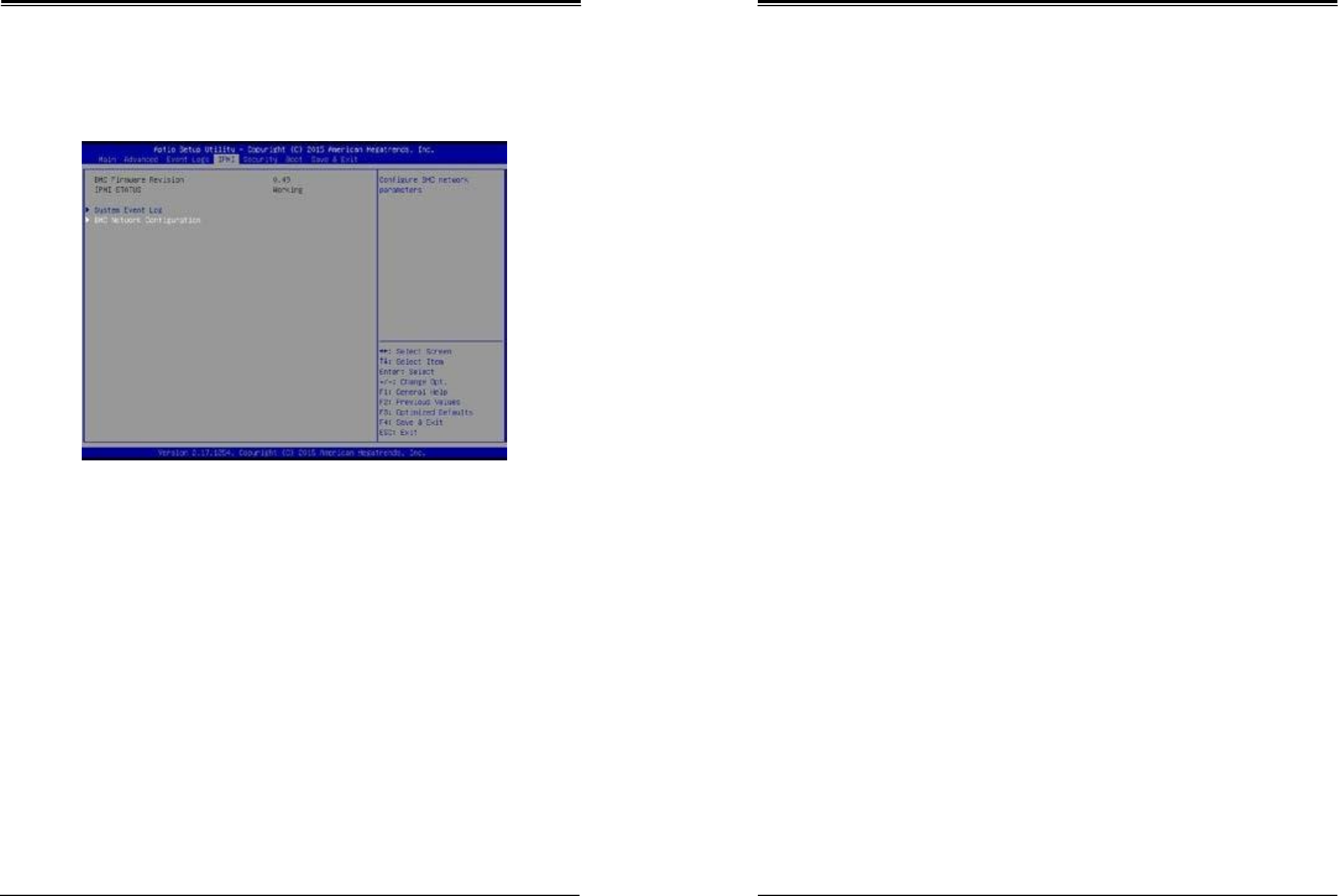
SuperWorkstation 5039D-I User's Manual
Chapter 6: BIOS
83
84
6.5
IPMI
Use this feature to configure Intelligent Platform Management Interface (IPMI) settings.
BMC Firmware Revision
This item indicates the IPMI firmware revision used in your system.
IPMI Status (Baseboard Management Controller)
This item indicates the status of the IPMI firmware installed in your system.
System Event Log
Enabling/Disabling Options
SEL Components
Select Enabled for all system event logging at bootup. The options are Enabled and Disabled.
Erasing Settings
Erase SEL
Select Yes, On next reset to erase all system event logs upon next system reboot. Select Yes,
On every reset to erase all system event logs upon each system reboot. Select No to keep all
system event logs after each system reboot. The options are No, Yes, On next reset, and
Yes, On every reset.
When SEL is Full
This feature allows the user to decide what the BIOS should do when the system event log
is full. Select Erase Immediately to erase all events in the log when the system event log is
full. The options are Do Nothing and Erase Immediately.
Note: After making changes on a setting, be sure to reboot the system for the changes
to take effect.
BMC Network Configuration
BMC Network Configuration
IPMI LAN Selection
This item displays the IPMI LAN setting. The default setting is Failover.
IPMI Network Link Status
This item displays the IPMI Network Link status. The default setting is Dedicated LAN.
Update IPMI LAN Configuration
Select Yes for the BIOS to implement all IP/MAC address changes at the next system boot.
The options are No and Yes.
*If the item above set to Yes, the following item will become available for user's
configuration:
Configuration Address Source
This feature allows the user to select the source of the IP address for this computer. If Static
is selected, you will need to know the IP address of this computer and enter it to the system
manually in the field. If DHCP is selected, the BIOS will search for a DHCP (Dynamic Host
Configuration Protocol) server in the network that is attached to and request the next available
IP address for this computer. The options are DHCP and Static.
Configuration Address Source
This item displays the current configuration address for this computer.
Station IP Address
This item displays the Station IP address for this computer. This should be in decimal and in
dotted quad form (i.e., 192.168.10.253).
Subnet Mask
This item displays the sub-network that this computer belongs to. The value of each three-
digit number separated by dots should not exceed 255.

SuperWorkstation 5039D-I User's Manual
Chapter 6: BIOS
85
86
Station MAC Address
This item displays the Station MAC address for this computer. Mac addresses are 6 two-digit
hexadecimal numbers.
Gateway IP Address
This item displays the Gateway IP address for this computer. This should be in decimal
and in dotted quad form (i.e., 172.31.0.1).
6.6
Security
This menu allows the user to configure the following security settings for the system.
Password Check
Select Setup for the system to check for a password at Setup. Select Always for the system
to check for a password at bootup or upon entering the BIOS Setup utility. The options are
Setup and Always.
Administrator Password
Press Enter to create a new, or change an existing Administrator password.
Secure Boot Menu
This section displays the contents of the following secure boot features:
•
System Mode
•
Secure Boot
•
Vendor Keys
Secure Boot
Use this item to enable secure boot. The options are Disabled and Enabled.

SuperWorkstation 5039D-I User's Manual
Chapter 6: BIOS
87
88
Secure Boot Mode
Use this item to select the secure boot mode. The options are Standard and Custom.
CSM Support
Select Enabled to support the EFI Compatibility Support Module (CSM), which provides
compatibility support for traditional legacy BIOS for system boot. The options are Enabled
and Disabled.
Key Management
This submenu allows the user to configure the following Key Management settings.
Provision Factory Default Keys
Select Enabled to install the default Secure-Boot keys set by the manufacturer. The options
are Disabled and Enabled.
Enroll All Factory Default Keys
Select Yes to install all default secure keys set by the manufacturer. The options are Yes
and No.
Save All Secure Boot Variables
This feature allows the user to decide if all secure boot variables should be saved.
Platform Key (PK)
This feature allows the user to configure the settings of the platform keys.
Set New Key
Select Yes to load the new platform keys (PK) from the manufacturer's defaults. Select No
to load the platform keys from a file. The options are Yes and No.
Key Exchange Key
Set New Key
Select Yes to load the KEK from the manufacturer's defaults. Select No to load the KEK from
a file. The options are Yes and No.
Append Key
Select Yes to add the KEK from the manufacturer's defaults list to the existing KEK. Select
No to load the KEK from a file. The options are Yes and No.
Authorized Signatures
Set New Key
Select Yes to load the database from the manufacturer's defaults. Select No to load the DB
from a file. The options are Yes and No.
Append Key
Select Yes to add the database from the manufacturer's defaults to the existing DB. Select
No to load the DB from a file. The options are Yes and No.
Forbiden Signatures
Set New Key
Select Yes to load the DBX from the manufacturer's defaults. Select No to load the DBX from
a file. The options are Yes and No.
Append Key
Select Yes to add the DBX from the manufacturer's defaults to the existing DBX. Select No
to load the DBX from a file. The options are Yes and No.
Authorized TimeStamps
Set New Key
Select Yes to load the DBT from the manufacturer's defaults. Select No to load the DBT from
a file. The options are Yes and No.
Append Key
Select Yes to add the DBT from the manufacturer's defaults list to the existing DBT. Select
No to load the DBT from a file. The options are Yes and No.
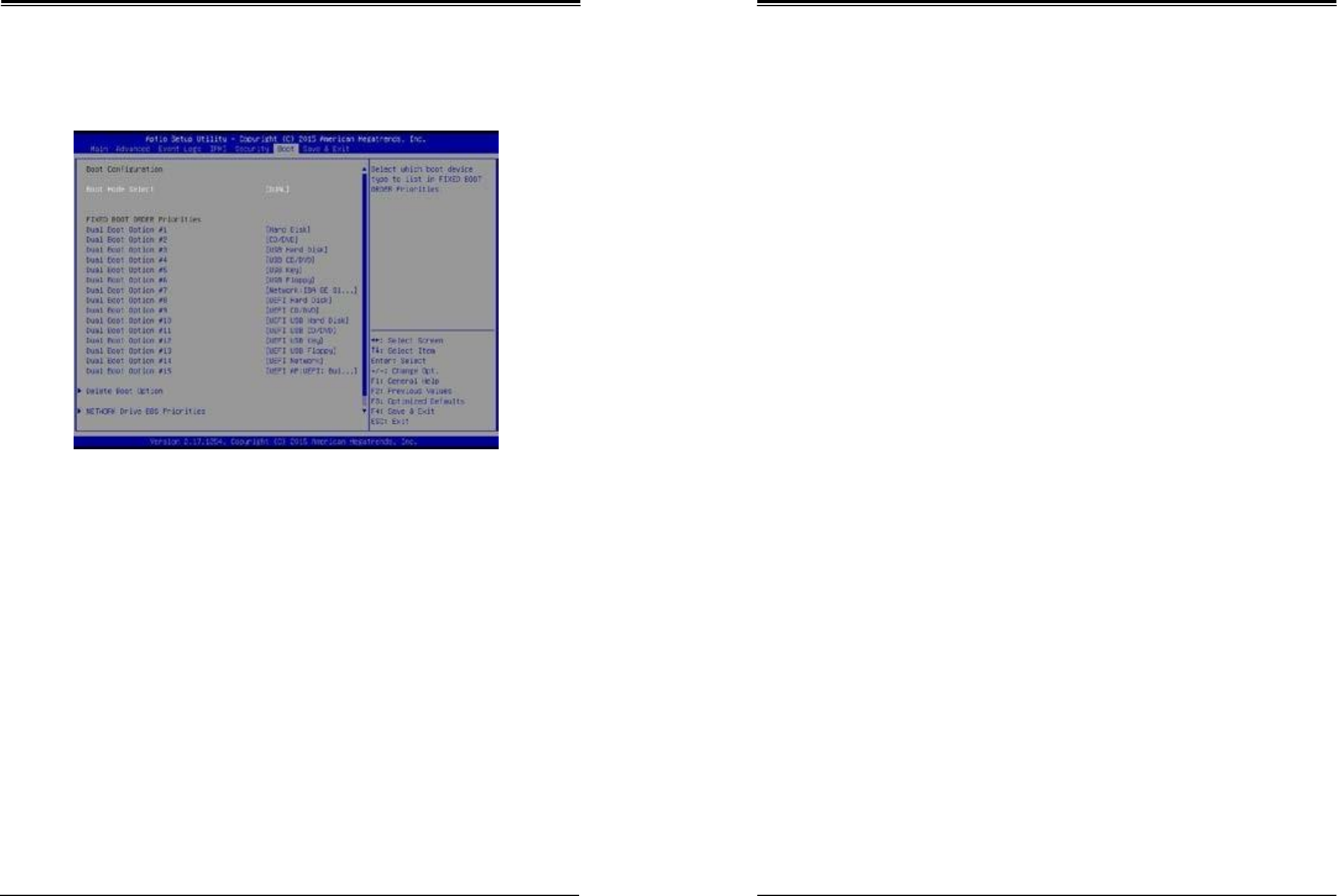
SuperWorkstation 5039D-I User's Manual
Chapter 6: BIOS
89
90
6.7
Boot
Use this feature to configure Boot Settings:
Boot Mode Select
Use this item to select the type of device that the system is going to boot from. The options
are Legacy, UEFI, and Dual. The default setting is Dual.
Fixed Boot Order Priorities
This option prioritizes the order of bootable devices that the system to boot from. Press
<Enter> on each entry from top to bottom to select devices.
*If the item above set to Legacy, UEFI/Dual the following items will be displayed:
•
Legacy/UEFI/Dual/Boot Order #1
•
Legacy/UEFI/Dual/Boot Order #2
•
Legacy/UEFI/Dual/Boot Order #3
•
Legacy/UEFI/Dual/Boot Order #4
•
Legacy/UEFI/Dual/Boot Order #5
•
Legacy/UEFI/Dual/Boot Order #6
•
Legacy/UEFI/Dual/Boot Order #7
•
Legacy/UEFI/Dual/Boot Order #8
•
Legacy/UEFI/Dual/Boot Order #9
•
Legacy/UEFI/Dual/Boot Order #10
•
Legacy/UEFI/Dual/Boot Order #11
•
Legacy/UEFI/Dual/Boot Order #12
•
Legacy/UEFI/Dual/Boot Order #13
•
Legacy/UEFI/Dual/Boot Order #14
•
Legacy/UEFI/Dual/Boot Order #15
Delete Boot Option
Use this feature to remove a pre-defined boot device from which the system will boot during
startup.
The settings are [any pre-defined boot device].
Hard Disk Drive BBS Priorities (Available when SATA HDD is connected onboard)
This feature allows the user to specify which hard disk drives are boot devices.
•
Legacy Boot Order #1
NETWORK Drive BBS Priorities
This feature allows the user to specify which UEFI network drive devices are boot devices.
•
Legacy Boot Order #1
•
Legacy Boot Order #2
UEFI Application Boot Priorities
This feature allows the user to specify which UEFI devices are boot devices.
•
UEFI Boot Order #1
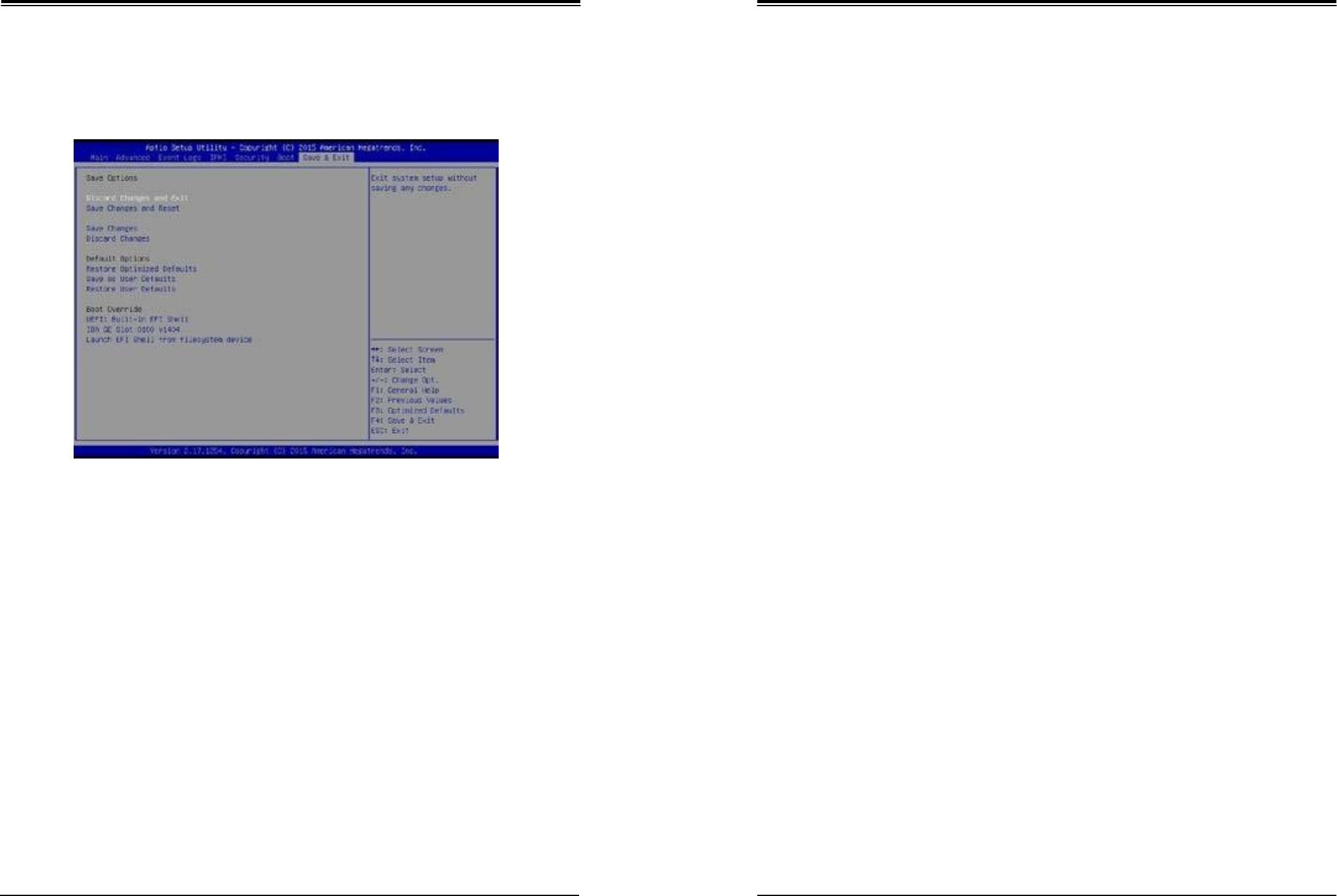
SuperWorkstation 5039D-I User's Manual
Chapter 6: BIOS
91
92
6.8
Save & Exit
Select the Exit tab from the BIOS setup utility screen to enter the Exit BIOS Setup screen.
Discard Changes and Exit
Select this option to quit the BIOS Setup without making any permanent changes to the
system configuration, and reboot the computer. Select Discard Changes and Exit from the
Exit menu and press <Enter>.
Save Changes and Reset
When you have completed the system configuration changes, select this option to leave the
BIOS setup utility and reboot the computer, so the new system configuration parameters can
take effect. Select Save Changes and Exit from the Exit menu and press <Enter>.
Save Changes
After completing the system configuration changes, select this option to save the changes
you have made. This will not reset (reboot) the system.
Discard Changes
Select this option and press <Enter> to discard all the changes and return to the AMI BIOS
utility Program.
Default Options
Restore Optimized Defaults
To set this feature, select Restore Optimized Defaults from the Save & Exit menu and press
<Enter>. These are factory settings designed for maximum system stability, but not for
maximum performance.
Save As User Defaults
To set this feature, select Save as User Defaults from the Exit menu and press <Enter>. This
enables the user to save any changes to the BIOS setup for future use.
Restore User Defaults
To set this feature, select Restore User Defaults from the Exit menu and press <Enter>. Use
this feature to retrieve user-defined settings that were saved previously.
Boot Override
Listed on this section are other boot options for the system (i.e., Built-in EFI shell). Select
an option and press <Enter>. Your system will boot to the selected boot option.
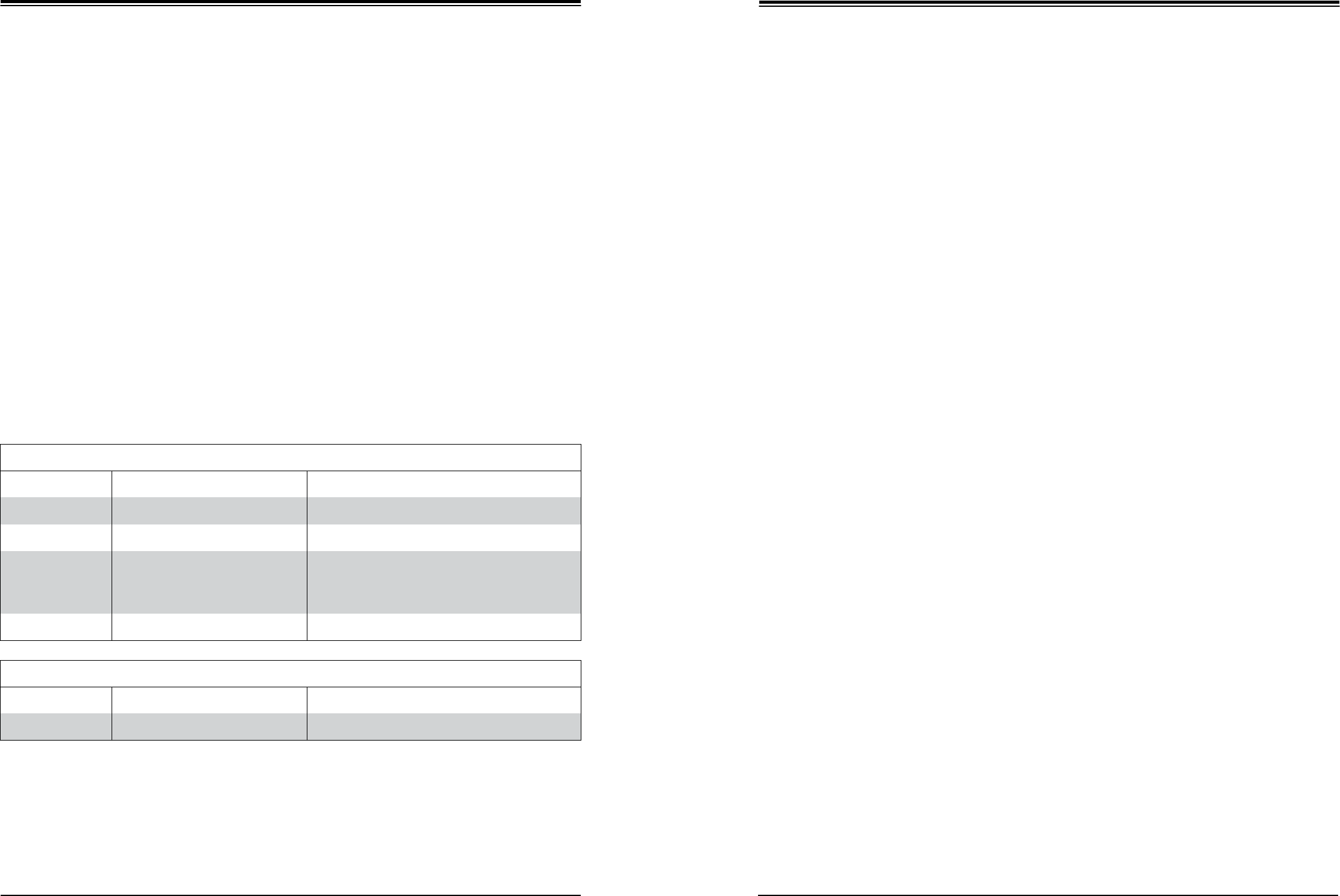
SuperWorkstation 5039D-I User's Manual
Appendix A: BIOS Codes
93
94
Appendix A
BIOS Error Codes
A-1 BIOS Error Beep (POST) Codes
During the POST (Power-On Self-Test) routines, which are performed each time the system
is powered on, errors may occur.
Non-fatal errors are those which, in most cases, allow the system to continue the boot-up
process. The error messages normally appear on the screen.
Fatal errors are those which will not allow the system to continue the boot-up procedure. If
a fatal error occurs, you should consult with your system manufacturer for possible repairs.
These fatal errors are usually communicated through a series of audible beeps. The numbers
on the fatal error list (on the following page) correspond to the number of beeps for the
corresponding error. All errors listed, with the exception of Beep Code 8, are fatal errors.
A-2 Additional BIOS POST Codes
The AMI BIOS supplies additional checkpoint codes, which are documented online at http://
www.supermicro.com/support/manuals/ ("AMI BIOS POST Codes User's Guide").
When BIOS performs the Power On Self Test, it writes checkpoint codes to I/O port 0080h.
If the computer cannot complete the boot process, a diagnostic card can be attached to the
computer to read I/O port 0080h (Supermicro p/n AOC-LPC80-20).
For information on AMI updates, please refer to http://www.ami.com/products/.
BIOS Error Beep (POST) Codes
Beep Code
Error Message
Description
1 beep
Refresh
Circuits have been reset (Ready to power up)
5 short, 1 long
Memory error
No memory detected in system
5 beeps
No con-in or con-out devices
Con-in includes USB or PS/2 keyboard, PCI or
serial console redirection, and IPMI KVM or SOL
Con-out includes the video controller, PCI or serial
console redirection, and IPMI SOL
1 or more beeps
Refresh
1 beep for each USB device detected
IPMI Error Codes
Beep Code
Error Message
Description
1 long continuous
System OH
System overheat condition

SuperWorkstation 5039D-I User's Manual
Appendix B: Standardized Warning Statements
95
96
Appendix B
Standardized Warning Statements for AC
Systems
B.1 About Standardized Warning Statements
The following statements are industry standard warnings, provided to warn the user of
situations which have the potential for bodily injury. Should you have questions or experience
difficulty, contact Supermicro's Technical Support department for assistance. Only certified
technicians should attempt to install or configure components.
Read this appendix in its entirety before installing or configuring components in the Supermicro
chassis.
Warning Definition
Warning! This warning symbol means danger. You are in a situation that could cause
bodily injury. Before you work on any equipment, be aware of the hazards involved
with electrical circuitry and be familiar with standard practices for preventing accidents.
警告の定義 この警告サインは危険を
意味します。
人身事故につながる可能性がありますので、いずれの機器でも動作させる前に、 電気回路に含
まれる危険性に注意して、標準的な事故防止策に精通して下さい。
此警告符号代表危险。
您正处于可能受到严重伤害的工作环境中。在您使用设备开始工作之前,必须充分意识到触电
的危险,并熟练掌握防止事故发生的标准工作程序。请根据每项警告结尾的声明号码找到此设
备的安全性警告说明的翻译文本。
此警告符號代表危險。
您正處於可能身體可能會受損傷的工作環境中。在您使用任何設備之前,請注意觸電的危險,
並且要熟悉預防事故發生的標準工作程序。請依照每一注意事項後的號碼找到相關的翻譯說明
內容。
Warnung
WICHTIGE SICHERHEITSHINWEISE
Dieses Warnsymbol bedeutet Gefahr. Sie befinden sich in einer Situation, die zu Verletzungen
führen kann. Machen Sie sich vor der Arbeit mit Geräten mit den Gefahren elektrischer
Schaltungen und den üblichen Verfahren zur Vorbeugung vor Unfällen vertraut. Suchen
Sie mit der am Ende jeder Warnung angegebenen Anweisungsnummer nach der jeweiligen
Ü bersetzung in den übersetzten Sicherheitshinweisen, die zusammen mit diesem Gerät
ausgeliefert wurden.
BEWAHREN SIE DIESE HINWEISE GUT AUF.
INSTRUCCIONES IMPORTANTES DE SEGURIDAD
Este símbolo de aviso indica peligro. Existe riesgo para su integridad física. Antes de
manipular cualquier equipo, considere los riesgos de la corriente eléctrica y familiarícese
con los procedimientos estándar de prevención de accidentes. Al final de cada advertencia
encontrará el número que le ayudará a encontrar el texto traducido en el apartado de
traducciones que acompaña a este dispositivo.
GUARDE ESTAS INSTRUCCIONES.
IMPORTANTES INFORMATIONS DE SÉ CURITÉ
Ce symbole d'avertissement indique un danger. Vous vous trouvez dans une situation pouvant
entraîner des blessures ou des dommages corporels. Avant de travailler sur un équipement,
soyez conscient des dangers liés aux circuits électriques et familiarisez-vous avec les
procédures couramment utilisées pour éviter les accidents. Pour prendre connaissance
des traductions des avertissements figurant dans les consignes de sécurité traduites qui
accompagnent cet appareil, référez-vous au numéro de l'instruction situé à la fin de chaque
avertissement.
CONSERVEZ CES INFORMATIONS.
ןונקת תורהצה הרהזא
תורהצה תואבה ןה תורהזא לע יפ ינקת היישעתה, לע תנמ ריהזהל תא שמתשמה ינפמ הלבח
תיזיפ תירשפא. הדימב שיו תולאש וא תולקתיה היעבב יהשלכ, שי רוציל רשק םע תקלחמ הכימת
תינכט לש ורקימרפוס. םיאנכט םיכמסומ דבלב םיאשר ןיקתהל וא רידגהל תא םיביכרה.
שי אורקל תא חפסנה ואולמב ינפל תנקתה וא תרדגה םיביכרה יזראמב ורקימרפוס.

SuperWorkstation 5039D-I User's Manual
Appendix B: Standardized Warning Statements
97
98
!
.
안전을 위한 주의사항
경고!
이 경고 기호는 위험이 있음을 알려 줍니다. 작업자의 신체에 부상을 야기 할 수 있는
상태에 있게 됩니다. 모든 장비에 대한 작업을 수행하기 전에 전기회로와 관련된
위험요소들을 확인하시고 사전에 사고를 방지할 수 있도록 표준 작업절차를 준수해 주시기
바랍니다.
해당 번역문을 찾기 위해 각 경고의 마지막 부분에 제공된 경고문 번호를 참조하십시오
BELANGRIJKE VEILIGHEIDSINSTRUCTIES
Dit waarschuwings symbool betekent gevaar. U verkeert in een situatie die lichamelijk letsel
kan veroorzaken. Voordat u aan enige apparatuur gaat werken, dient u zich bewust te zijn
van de bij een elektrische installatie betrokken risico's en dient u op de hoogte te zijn van de
standaard procedures om ongelukken te voorkomen. Gebruik de nummers aan het eind van
elke waarschuwing om deze te herleiden naar de desbetreffende locatie.
BEWAAR DEZE INSTRUCTIES
Installation Instructions
Warning! Read the installation instructions before connecting the system to the power
source.
設置手順書 システムを電源に接続する前に、設置手順書をお読
み下さい。
警告 将此系统连接电源前,请先阅读安装说明。
警告 將系統與電源連接前,請先閱讀安裝說
明。
Warnung
Vor dem Anschließen des Systems an die Stromquelle die Installationsanweisungen lesen.
¡Advertencia!
Lea las instrucciones de instalación antes de conectar el sistema a la red de alimentación.
Attention
Avant de brancher le système sur la source d'alimentation, consulter les directives d'installation.
שי אורקל תא תוארוה הנקתה ינפל רוביח תכרעמה רוקמל חתמ.
시스템을 전원에 연결하기 전에 설치 안내를 읽어주십시오.
Waarschuwing
Raadpleeg de installatie-instructies voordat u het systeem op de voedingsbron aansluit.
Circuit Breaker
Warning! This product relies on the building's installation for short-circuit (overcurrent)
protection. Ensure that the protective device is rated not greater than: 250 V, 20 A.
サーキット・ブレーカー この製品は、短絡(過電流)保護装置がある建物での設
置を前提としています。 保護装置の定格
が
250
V
、
20
A
を超えないことを確
認下さい。
警告 此产品的短路(过载电流)保护由建筑物的供电系统提供,确保短路保护设备的额定电流不
大于 250V,20A。
警告 此產品的短路(過載電流)保護由建築物的供電系統提供,確保短路保護設備的額定電流不
大於 250V,20A。

SuperWorkstation 5039D-I User's Manual
Appendix B: Standardized Warning Statements
99
100
Warnung
Dieses Produkt ist darauf angewiesen, dass im Gebäude ein Kurzschluss- bzw.
Ü berstromschutz installiert ist. Stellen Sie sicher, dass der Nennwert der Schutzvorrichtung
nicht mehr als: 250 V, 20 A beträgt.
¡Advertencia!
Este equipo utiliza el sistema de protección contra cortocircuitos (o sobrecorrientes) del
edificio. Asegúrese de que el dispositivo de protección no sea superior a: 250 V, 20 A.
Attention
Pour ce qui est de la protection contre les courts-circuits (surtension), ce produit dépend de
l'installation électrique du local. Vérifiez que le courant nominal du dispositif de protection
n'est pas supérieur à :250 V, 20 A.
רצומ הז ךמתסמ לע הנגה תנקתומה םינבמב תעינמל רצק ילמשח. שי אדוול יכ
רישכמה ןגמה ינפמ רצקה ילמשחה אוה אל רתוי מ20A- 60VDC,
:
250VDC 20A,
경고!
이 제품은 전원의 단락(과전류)방지에 대해서 전적으로 건물의 관련 설비에 의존합니다.
보호장치의 정격이 반드시 250V(볼트), 20A(암페어)를 초과하지 않도록 해야 합니다.
Waarschuwing
Dit product is afhankelijk van de kortsluitbeveiliging (overspanning) van uw electrische
installatie. Controleer of het beveiligde aparaat niet groter gedimensioneerd is dan 250V, 20A.
Power Disconnection Warning
Warning! The system must be disconnected from all sources of power and the power
cord removed from the power supply module(s) before accessing the chassis interior
to install or remove system components.
電源切断の警告 システムコンポーネントの取り付けまたは取り外しのために、シャーシー内部に
アクセスするには、
システムの電源はすべてのソースから切断され、電源コードは電源モジュールから取り外す必要が
あります。
警告 在你打开机箱并安装或移除内部器件前,必须将系统完全断电,并移除电源线。
警告 在您打開機殼安裝或移除內部元件前,必須將系統完全斷電,並移除電源線。
Warnung
Das System muss von allen Quellen der Energie und vom Netzanschlusskabel getrennt sein,
das von den Spg.Versorgungsteilmodulen entfernt wird, bevor es auf den Chassisinnenraum
zurückgreift, um Systemsbestandteile anzubringen oder zu entfernen.
¡Advertencia!
El sistema debe ser disconnected de todas las fuentes de energía y del cable eléctrico quitado
de los módulos de fuente de alimentación antes de tener acceso el interior del chasis para
instalar o para quitar componentes de sistema.
Attention
Le système doit être débranché de toutes les sources de puissance ainsi que de son cordon
d'alimentation secteur avant d'accéder à l'intérieur du chassis pour installer ou enlever des
composants de systéme.
הרהזא!
שי קתנל תא תכרעמה לכמ תורוקמ למשחה שיו ריסהל תא לבכ ילמשחה קפסהמ
ינפל השיג קלחל ימינפה לש זראמה ךרוצל תנקתה וא תרסה םיביכר.
הרהזא ינפמ קותינ
ילמשח

SuperWorkstation 5039D-I User's Manual
Appendix B: Standardized Warning Statements
101
102
경고!
Attention
Il est vivement recommandé de confier l'installation, le remplacement et la maintenance de
ces équipements à des personnels qualifiés et expérimentés.
הרהזא!
תווצ ךמסומ דבלב יאשר ןיקתהל, ףילחהל תא דויצה וא תתל תוריש רובע דויצה.
시스템에 부품들을 장착하거나 제거하기 위해서는 섀시 내부에 접근하기 전에 반드시 전원
공급장치로부터 연결되어있는 모든 전원과 전기코드를 분리해주어야 합니다.
Waarschuwing
Voordat u toegang neemt tot het binnenwerk van de behuizing voor het installeren of
verwijderen van systeem onderdelen, dient u alle spanningsbronnen en alle stroomkabels
aangesloten op de voeding(en) van de behuizing te verwijderen
Equipment Installation
Warning! Only trained and qualified personnel should be allowed to install, replace,
or service this equipment.
機器の設置
トレーニングを受け認定された人だけがこの装置の設置、交換、またはサービスを許可されていま
す。
警告 只有经过培训且具有资格的人员才能进行此设备的安装、更换和维修。
警告 只有經過受訓且具資格人員才可安裝、更換與維修此設備。
Warnung
Das Installieren, Ersetzen oder Bedienen dieser Ausrüstung sollte nur geschultem,
qualifiziertem Personal gestattet werden.
¡Advertencia!
Solamente el personal calificado debe instalar, reemplazar o utilizar este equipo.
경고!
훈련을 받고 공인된 기술자만이 이 장비의 설치, 교체 또는 서비스를 수행할 수 있습니다.
Waarschuwing
Deze apparatuur mag alleen worden geïnstalleerd, vervangen of hersteld door geschoold en
gekwalificeerd personeel.
Restricted Area
Warning! This unit is intended for installation in restricted access areas. A restricted
access area can be accessed only through the use of a special tool, lock and key, or
other means of security. (This warning does not apply to workstations).
アクセス制限区域 このユニットは、アクセス制限区域に設置されること
を想定しています。
アクセス制限区域は、特別なツール、鍵と錠前、その他のセキュリティの手段を用いてのみ出入りが
可能です。
警告 此部件应安装在限制进出的场所,限制进出的场所指只能通过使用特殊工具、锁和钥匙或
其它 安全手段进出的场所。
警告 此裝置僅限安裝於進出管制區域,進出管制區域係指僅能以特殊工具、鎖頭及鑰匙或其他
安全 方式才能進入的區域。
SuperWorkstation 5039D-I User's Manual
Appendix B: Standardized Warning Statements
103
104
Warnung
Diese Einheit ist zur Installation in Bereichen mit beschränktem Zutritt vorgesehen. Der Zutritt
zu derartigen Bereichen ist nur mit einem Spezialwerkzeug, Schloss und Schlüssel oder einer
sonstigen Sicherheitsvorkehrung möglich.
¡Advertencia!
Esta unidad ha sido diseñada para instalación en áreas de acceso restringido. Sólo puede
obtenerse acceso a una de estas áreas mediante la utilización de una herramienta especial,
cerradura con llave u otro medio de seguridad.
Attention
Cet appareil doit être installée dans des zones d'accès réservés. L'accès à une zone d'accès
réservé n'est possible qu'en utilisant un outil spécial, un mécanisme de verrouillage et une
clé, ou tout autre moyen de sécurité.
רוזא םע השיג תלבגומ
הרהזא!
שי ןיקתהל תא הדיחיה םירוזאב שיש םהב תלבגה השיג. השיגה תנתינ תרזעב
ילכ החטבא דבלב (חתפמ, לוענמ דכו.)'
Battery Handling
Warning! There is the danger of explosion if the battery is replaced incorrectly. Replace
the battery only with the same or equivalent type recommended by the manufacturer.
Dispose of used batteries according to the manufacturer's instructions
電池の取り扱い 電池交換が正しく行われなかった場合、破裂の危険性があります。交換する電池は
メーカーが推 奨する型、または同等のものを使用下さい。使用済電池は製造元の指示に従って処
分して下さい。
警告 电池更换不当会有爆炸危险。请只使用同类电池或制造商推荐的功能相当的电池更换原有
电 池。请按制造商的说明处理废旧电池。
警告 電池更換不當會有爆炸危險。請使用製造商建議之相同或功能相當的電池更換原有電池。
請按 照製造商的說明指示處理廢棄舊電池。
Warnung
Bei Einsetzen einer falschen Batterie besteht Explosionsgefahr. Ersetzen Sie die Batterie nur
durch den gleichen oder vom Hersteller empfohlenen Batterietyp. Entsorgen Sie die benutzten
Batterien nach den Anweisungen des Herstellers.
.
Attention
경고!
Danger d'explosion si la pile n'est pas remplacée correctement. Ne la remplacer que par une
pile de type semblable ou équivalent, recommandée par le fabricant. Jeter les piles usagées
conformément aux instructions du fabricant.
이 장치는 접근이 제한된 구역에 설치하도록 되어있습니다. 특수도구, 잠금 장치 및 키,
또는 기타 보안 수단을 통해서만 접근 제한 구역에 들어갈 수 있습니다.
Waarschuwing
Dit apparaat is bedoeld voor installatie in gebieden met een beperkte toegang. Toegang tot
dergelijke gebieden kunnen alleen verkregen worden door gebruik te maken van speciaal
gereedschap, slot en sleutel of andere veiligheidsmaatregelen.
¡Advertencia!
Existe peligro de explosión si la batería se reemplaza de manera incorrecta. Reemplazar la
batería exclusivamente con el mismo tipo o el equivalente recomendado por el fabricante.
Desechar las baterías gastadas según las instrucciones del fabricante.
הרהזא!
תמייק תנכס ץוציפ לש וסההלל הדימב הפלחוהו ךרדב אל הניקת. שי ףילחהל
תא הללוסה גוסב םאותה תרבחמ ןרצי תצלמומ.
קוליס תוללוסה תושמושמה שי עצבל יפל תוארוה ןרציה.

SuperWorkstation 5039D-I User's Manual
Appendix B: Standardized Warning Statements
105
106
경고!
¡Advertencia!
Puede que esta unidad tenga más de una conexión para fuentes de alimentación. Para cortar
por completo el suministro de energía, deben desconectarse todas las conexiones.
Attention
Cette unité peut avoir plus d'une connexion d'alimentation. Pour supprimer toute tension et tout
courant électrique de l'unité, toutes les connexions d'alimentation doivent être débranchées.
배터리가 올바르게 교체되지 않으면 폭발의 위험이 있습니다. 기존 배터리와 동일하거나 제
조사에서 권장하는 동등한 종류의 배터리로만 교체해야 합니다. 제조사의 안내에 따라 사용
된 배터리를 처리하여 주십시오.
Waarschuwing
Er is ontploffingsgevaar indien de batterij verkeerd vervangen wordt. Vervang de batterij
slechts met hetzelfde of een equivalent type die door de fabrikant aanbevolen wordt. Gebruikte
batterijen dienen overeenkomstig fabrieksvoorschriften afgevoerd te worden.
Redundant Power Supplies
경고!
םא םייק רתוי קפסמ דחא
הרהזא!
הדחיל שי רתוי רוביחמ דחא לש קפס. שי ריסהל תא לכ םירוביחה לע תנמ ןקורל
תא הדיחיה.
.
Warning! This unit might have more than one power supply connection. All connec-
tions must be removed to de-energize the unit.
冗長電源装置 このユニットは複数の電源装置が接続されている場合があります。
ユニットの電源を切るためには、すべての接続を取り外さなければなりません。
警告 此部件连接的电源可能不止一个,必须将所有电源断开才能停止给该部件供
电。
警告 此裝置連接的電源可能不只一個,必須切斷所有電源才能停止對該裝置的供
電。
Warnung
Dieses Gerät kann mehr als eine Stromzufuhr haben. Um sicherzustellen, dass der Einheit
kein trom zugeführt wird, müssen alle Verbindungen entfernt werden.
이 장치에는 한 개 이상의 전원 공급 단자가 연결되어 있을 수 있습니다. 이 장치에 전원을
차단하기 위해서는 모든 연결 단자를 제거해야만 합니다.
Waarschuwing
Deze eenheid kan meer dan één stroomtoevoeraansluiting bevatten. Alle aansluitingen dienen
verwijderd te worden om het apparaat stroomloos te maken.
SuperWorkstation 5039D-I User's Manual
Appendix B: Standardized Warning Statements
107
108
Backplane Voltage
Warning! Hazardous voltage or energy is present on the backplane when the system
is operating. Use caution when servicing.
バックプレーンの電圧 システムの稼働中は危険な電圧または電力が、バックプレー
ン上にかかっています。 修理する際には注意ください。
警告 当系统正在进行时,背板上有很危险的电压或能量,进行维修时务必小
心。
警告 當系統正在進行時,背板上有危險的電壓或能量,進行維修時務必小心。
Warnung
Wenn das System in Betrieb ist, treten auf der Rückwandplatine gefährliche Spannungen
oder Energien auf. Vorsicht bei der Wartung.
¡Advertencia!
Cuando el sistema está en funcionamiento, el voltaje del plano trasero es peligroso. Tenga
cuidado cuando lo revise.
Attention
Lorsque le système est en fonctionnement, des tensions électriques circulent sur le fond de
panier. Prendre des précautions lors de la maintenance.
경고!
시스템이 동작 중일 때 후면판 (Backplane)에는 위험한 전압이나 에너지가 발생 합니다.
서비스 작업 시 주의하십시오.
Waarschuwing
Een gevaarlijke spanning of energie is aanwezig op de backplane wanneer het systeem in
gebruik is. Voorzichtigheid is geboden tijdens het onderhoud.
Comply with Local and National Electrical Codes
Warning! Installation of the equipment must comply with local and national electrical
codes.
地方および国の電気規格に準拠 機器の取り付けはその地方および国の電気規格に準拠する必
要があります。
警告 设备安装必须符合本地与本国电气法规。
警告 設備安裝必須符合本地與本國電氣法規。
Warnung
Die Installation der Geräte muss den Sicherheitsstandards entsprechen.
הרהזא!
תמייק תנכס חתמ לנפב ירוחאה ןמזב לועפת תכרעמה. שי רהזיהל ךלהמב
הדובעה.
¡Advertencia!
La instalacion del equipo debe cumplir con las normas de electricidad locales y nacionales.
Attention
L'équipement doit être installé conformément aux normes électriques nationales et locales.
חתמ לנפב ירוחאה
SuperWorkstation 5039D-I User's Manual
Appendix B: Standardized Warning Statements
109
110
הרהזא!
תנקתה דויצה תבייח תויהל תמאות יקוחל למשחה םיימוקמה םייצראהו.
Attention
La mise au rebut ou le recyclage de ce produit sont généralement soumis à des lois et/ou
directives de respect de l'environnement. Renseignez-vous auprès de l'organisme compétent.
경고!
הרהזא!
קוליס יפוס לש רצומ הז בייח תויהל םאתהב תויחנהל יקוחו הנידמה.
현 지역 및 국가의 전기 규정에 따라 장비를 설치해야 합니다.
Waarschuwing
Bij installatie van de apparatuur moet worden voldaan aan de lokale en nationale
elektriciteitsvoorschriften.
Product Disposal
Warning! Ultimate disposal of this product should be handled according to all national
laws and regulations.
製品の廃棄 この製品を廃棄処分する場合、国の関係する全ての法律・条例に従い処理する必要が
あります。
警告 本产品的废弃处理应根据所有国家的法律和规章进行。
警告 本產品的廢棄處理應根據所有國家的法律和規章進行。
Warnung
Die Entsorgung dieses Produkts sollte gemäß allen Bestimmungen und Gesetzen des Landes
erfolgen.
¡Advertencia!
Al deshacerse por completo de este producto debe seguir todas las leyes y reglamentos
nacionales.
경고!
이 제품은 해당 국가의 관련 법규 및 규정에 따라 폐기되어야 합니다.
Waarschuwing
De uiteindelijke verwijdering van dit product dient te geschieden in overeenstemming met alle
nationale wetten en reglementen.
Hot Swap Fan Warning
Warning! The fans might still be turning when you remove the fan assembly from the
chassis. Keep fingers, screwdrivers, and other objects away from the openings in the
fan assembly's housing.
ファン・ホットスワップの警告 シャーシから冷却ファン装置を取り外した際、ファンがまだ回転して
いる可能性があります。ファン の開口部に、指、ドライバー、およびその他のものを近づけないで
下さい。
警告 当您从机架移除风扇装置,风扇可能仍在转动。小心不要将手指、螺丝起子和其他物品太
靠近 风扇
警告 當您從機架移除風扇裝置,風扇可能仍在轉動。小心不要將手指、螺絲起子和其他物品太
靠近 風扇。
םואית יקוח למשחה יצראה
קוליס רצומה

SuperWorkstation 5039D-I User's Manual
Appendix B: Standardized Warning Statements
111
112
Warnung
Die Lüfter drehen sich u. U. noch, wenn die Lüfterbaugruppe aus dem Chassis genommen
wird. Halten Sie Finger, Schraubendreher und andere Gegenstände von den Ö ffnungen des
Lüftergehäuses entfernt.
¡Advertencia!
Los ventiladores podran dar vuelta cuando usted quite ell montaje del ventilador del chasis.
Mandtenga los dedos, los destornilladores y todos los objetos lejos de las aberturas del
ventilador
Attention
Il est possible que les ventilateurs soient toujours en rotation lorsque vous retirerez le bloc
ventilateur du châssis. Prenez garde à ce que doigts, tournevis et autres objets soient éloignés
du logement du bloc ventilateur.
הרהזא!
רשאכ םיריסמ תא יקלח ררוואמה זראמהמ, ןכתי םיררוואמהו ןיידע םידבוע. שי
קיחרהל קחרמל חוטב תא תועבצאה ילכו הדובע םינוש םיחתפהמ ךותב ררוואמה
.
경고!
섀시로부터 팬 조립품을 제거할 때 팬은 여전히 회전하고 있을 수 있습니다. 팬 조림품
외관의 열려있는 부분들로부터 손가락 및 스크류드라이버, 다른 물체들이 가까이 하지
않도록 배치해 주십시오.
Waarschuwing
Het is mogelijk dat de ventilator nog draait tijdens het verwijderen van het ventilatorsamenstel
uit het chassis. Houd uw vingers, schroevendraaiers en eventuele andere voorwerpen uit de
buurt van de openingen in de ventilatorbehuizing.
Power Cable and AC Adapter
Warning! When installing the product, use the provided or designated connection
cables, power cables and AC adaptors. Using any other cables and adaptors could
cause a malfunction or a fire. Electrical Appliance and Material Safety Law prohibits
the use of UL or CSA -certified cables (that have UL/CSA shown on the code) for any
other electrical devices than products designated by Supermicro only.
電源コードと AC アダプター 製品を設置する場合、提供または指定された接続ケーブル、電源コード
と
A
C
アダプターを使用下さ い。他のケーブルやアダプタを使用すると故障や火災の原因になるこ
とがあります。電気用品安全
法は、
UL
または
CSA
認定
のケーブ
ル
(UL/CSE
マークがコードに
表記
)
を
Supermicro
が指定する製
品以外に使用することを禁止しています。
警告 安装此产品时,请使用本身提供的或指定的连接线,电源线和电源适配器.使用其它线材或
适配 器可能会引起故障或火灾。除了 Supermicro 所指定的产品,电气用品和材料安全法律规
定禁止 使用未经 UL 或CSA 认证的线材。(线材上会显示 UL/CSA 符号)。
警告 安裝此產品時,請使用本身提供的或指定的連接線,電源線和電源適配器.使用其它線材或
適配 器可能會引起故障或火災。除了 Supermicro 所指定的產品,電氣用品和材料安全法律規
定禁止 使用未經 UL 或CSA 認證的線材。(線材上會顯示 UL/CSA 符號)。
Warnung
Bei der Installation des Produkts, die zur Verfügung gestellten oder benannt Anschlusskabel,
Stromkabel und Netzteile. Verwendung anderer Kabel und Adapter kann zu einer Fehlfunktion
oder ein Brand entstehen. Elektrische Geräte und Material Safety Law verbietet die
Verwendung von UL-oder CSA-zertifizierte Kabel, UL oder CSA auf der Code für alle anderen
elektrischen Geräte als Produkte von Supermicro nur bezeichnet gezeigt haben.
¡Advertencia!
Al instalar el producto, utilice los cables de conexión previstos o designados, los cables y
adaptadores de CA. La utilización de otros cables y adaptadores podría ocasionar un mal
funcionamiento o un incendio. Aparatos Eléctricos y la Ley de Seguridad del Material prohíbe
el uso de UL o CSA cables certificados que tienen UL o CSA se muestra en el código de
otros dispositivos eléctricos que los productos designados por Supermicro solamente.

SuperWorkstation 5039D-I User's Manual
113
Attention
Lors de l'installation du produit, utilisez les bables de connection fournis ou désigné.
L'utilisation d'autres cables et adaptateurs peut provoquer un dysfonctionnement ou un
incendie. Appareils électroménagers et de loi sur la sécurité Matériel interdit l'utilisation de UL
ou CSA câbles certifiés qui ont UL ou CSA indiqué sur le code pour tous les autres appareils
électriques que les produits désignés par Supermicro seulement.
םיילמשח ימאתמו
AC
רשא
AC
הרהזא!
רשאכ םיניקתמ תא רצומה, שי שמתשהל םילבכב, םיקפס םימאתמו
ודעונ וקפוסו םשל ךכ. שומיש לכב לבכ וא םאתמ רחא לוכי םורגל הלקתל וא
רצק ילמשח. לע יפ יקוח שומיש ירישכמב למשח יקוחו תוחיטב, םייק רוסיא
שמתשהל םילבכב םיכמסומה ב-
UL
וא ב-
CSA
(ראשכ עיפומ םהילע דוק לש
)
UL/CSA
רובע לכ רצומ ילמשח רחא אלש ןיוצ לע ידי ורקימקרפוס דבלב.
.
.
UL وأ CSA
Supermicro
)
(UL/CSA
경고!
제품을 설치할 때에는 제공되거나 지정된 연결케이블과 전원케이블, AC 어댑터를 사용해야
합니다. 그 밖의 다른 케이블들이나 어댑터들은 고장 또는 화재의 원인이 될 수 있습니다.
전기용품안전법 (Electrical Appliance and Material Safety Law)은 슈퍼마이크로에서
지정한 제품들 외에는 그 밖의 다른 전기 장치들을 위한 UL 또는 CSA 에서 인증한
케이블( 전선 위에 UL/CSA 가 표시)들의 사용을 금지합니다.
Waarschuwing
Bij het installeren van het product, gebruik de meegeleverde of aangewezen kabels,
stroomkabels en adapters. Het gebruik van andere kabels en adapters kan leiden tot een
storing of een brand. Elektrisch apparaat en veiligheidsinformatiebladen wet verbiedt het
gebruik van UL of CSA gecertificeerde kabels die UL of CSA die op de code voor andere
elektrische apparaten dan de producten die door Supermicro alleen.

SuperWorkstation 5039D-I User's Manual
Appendix C: System Specifications
114
115
Appendix C
System Specifications
Processors
Single Intel® E3-1200 v5 and 6th Gen Core™ i3, Pentium and Celeron processors in LGA 1151 (H4) type socket
Note: Please refer to the motherboard specifications pages on our website for updates to supported processors.
Chipset
Intel C232 chipset
BIOS
128 MB AMI® Flash ROM
Memory
Four 288-pin DIMM slots that can support up to 64 GB of unbuffered ECC DDR4-2133/1866/1600/1333MHz SDRAM
Note: See the memory section in Chapter 3 for details and our website for updates to supported memory.
SATA Controller
On-chip (C232) controller
Drive Bays
Up to four 3.5" or 2.5" internal drives
PCI Expansion Slots
One PCI Express 3.0 x4 in x8 slots (PCH slot 5)
One PCI Express 3.0 x8 in x16 slot (CPU slot 6)
One PCI Express 3.0 x8 slot (CPU slot 7)
Motherboard
X11SSL-F; Micro ATX form factor (9.6 x 9.6 in. / 244 x 244 mm.)
Chassis
SC731i-300B; 1U Rackmount, 17.2 x 1.7 x 20 in. / 437 x 43 x 508 mm. (W x H x D)
System Cooling
Two 4-cm high-performance fans
Power Supply
Model: PWS-305-PQ
AC Input Voltages: 100-240 VAC
Rated Input Current: 5A maximum
Rated Input Frequency: 50-60 Hz
Rated Output Power: 300W
Rated Output Voltages: +5V (19A), +3.3V (16A), +12V (11A), -12V (0.15A), +5Vsb (2A)
Operating Environment
Operating Temperature: 5º to 35º C (41º to 95º F)
Non-operating Temperature: -40º to 60º C (-40º to 140º F)
Operating Relative Humidity: 8% to 90% (non-condensing) Non-
operating Relative Humidity: 5% to 95% (non-condensing)
Regulatory Compliance
Electromagnetic Emissions: FCC Class A, EN 55022 Class A, EN 61000-3-2/3-3, CISPR 22 Class A
Electromagnetic Immunity: EN 55024/CISPR 24, (EN 61000-4-2, EN 61000-4-3, EN 61000-4-4, EN 61000-4-5, EN 61000-4-6,
EN 61000-4-8, EN 61000-4-11)
Safety: CSA/EN/IEC/UL 60950-1 Compliant, UL or CSA Listed (USA and Canada), CE Marking (Europe)
Perchlorate Warning
California Best Management Practices Regulations for Perchlorate Materials: This Perchlorate warning applies only to products
containing CR (Manganese Dioxide) Lithium coin cells. “Perchlorate Material-special handling may apply. See www.dtsc.ca.gov/
hazardouswaste/perchlorate”
