Acer Aspire 3510 S.G_AS1690_AS3510_CH1 User Manual To The Dd968bdd B46a 448c 8c76 Af9134e4d248
User Manual: Acer Aspire 3510 to the manual
Open the PDF directly: View PDF ![]() .
.
Page Count: 125 [warning: Documents this large are best viewed by clicking the View PDF Link!]
- Aspire 1690/Aspire 3510 Service Guide
- Revision History
- Copyright
- Disclaimer
- Conventions
- Preface
- T.O.C
- S.G_AS1690.AS3510_CH1
- S.G_AS1690_AS3510_CH2
- S.G_AS1690_AS3510_CH3
- S.G_AS1690_AS3510_CH4
- S.G_AS1690_AS3510_CH5
- S.G_AS1690_AS3510_CH6
- S.G_AS1690_AS3510_AppA
- S.G_AS1690_AS3510_AppB
- S.G_AS1690_AS3510_AppC

Aspire 1690
Aspire 3510
Service Guide
PRINTED IN TAIWAN
NOTE: Please refer to Kestrel Service CD P/N:VD.A27V7.001
Service guide files and updates are available
on the ACER/CSD web; for more information,
please refer to http://csd.acer.com.tw

II
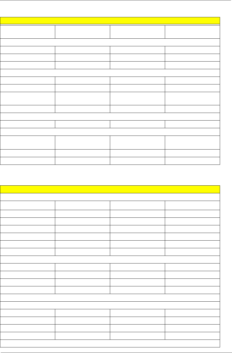
Revision History
Please refer to the table below for the updates made on Aspire1690 and Aspire 3510 service guide.
Date Chapter Updates

III
Copyright
Copyright © 2005 by Acer Incorporated. All rights reserved. No part of this publication may be reproduced,
transmitted, transcribed, stored in a retrieval system, or translated into any language or computer language, in
any form or by any means, electronic, mechanical, magnetic, optical, chemical, manual or otherwise, without
the prior written permission of Acer Incorporated.
Disclaimer
The information in this guide is subject to change without notice.
Acer Incorporated makes no representations or warranties, either expressed or implied, with respect to the
contents hereof and specifically disclaims any warranties of merchantability or fitness for any particular
purpose. Any Acer Incorporated software described in this manual is sold or licensed "as is". Should the
programs prove defective following their purchase, the buyer (and not Acer Incorporated, its distributor, or its
dealer) assumes the entire cost of all necessary servicing, repair, and any incidental or consequential
damages resulting from any defect in the software.
Acer is a registered trademark of Acer Corporation.
Intel is a registered trademark of Intel Corporation.
Pentium and Pentium II/III are trademarks of Intel Corporation.
Other brand and product names are trademarks and/or registered trademarks of their respective holders.

IV
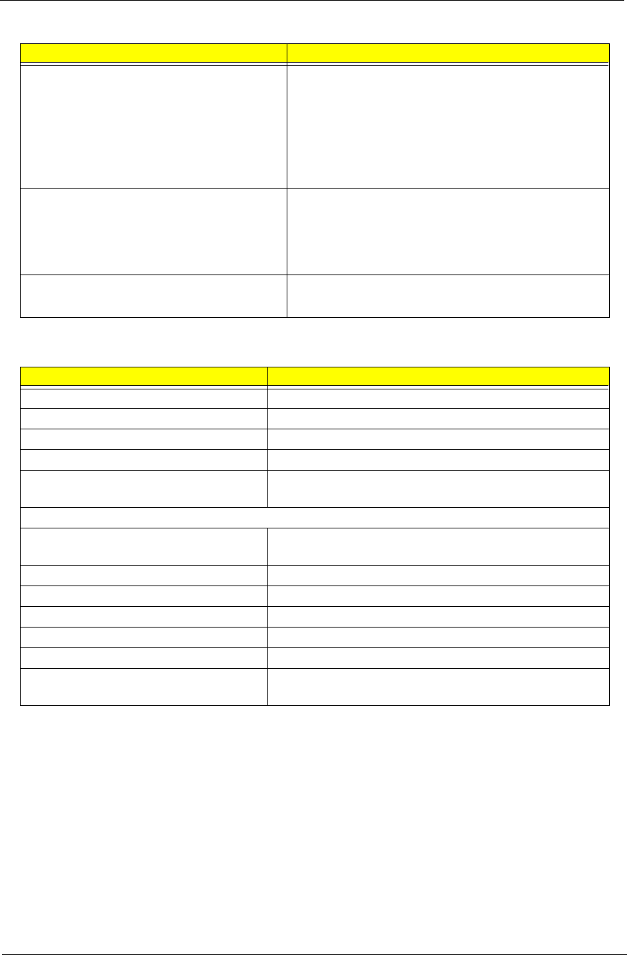
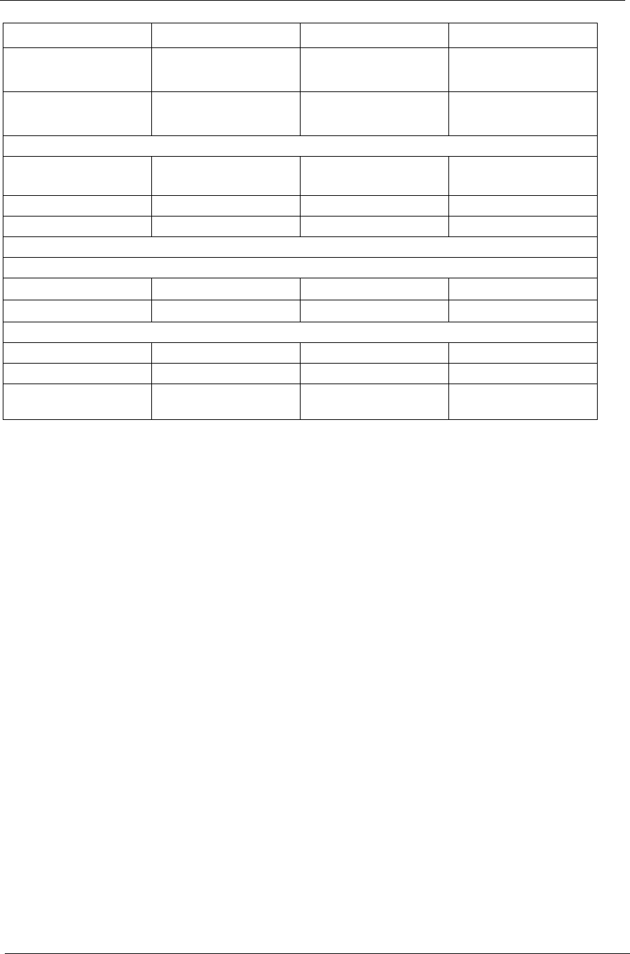
Conventions
The following conventions are used in this manual:
SCREEN
MESSAGES
Denotes actual messages that appear
on screen.
NOTE Gives bits and pieces of additional
information related to the current
topic.
WARNING Alerts you to any damage that might
result from doing or not doing specific
actions.
CAUTION Gives precautionary measures to
avoid possible hardware or software
problems.
IMPORTANT Reminds you to do specific actions
relevant to the accomplishment of
procedures.

V
Preface
Before using this information and the product it supports, please read the following general information.
1. This Service Guide provides you with all technical information relating to the BASIC CONFIGURATION
decided for Acer's "global" product offering. To better fit local market requirements and enhance product
competitiveness, your regional office MAY have decided to extend the functionality of a machine (e.g.
add-on card, modem, or extra memory capability). These LOCALIZED FEATURES will NOT be covered
in this generic service guide. In such cases, please contact your regional offices or the responsible
personnel/channel to provide you with further technical details.
2. Please note WHEN ORDERING FRU PARTS, that you should check the most up-to-date information
available on your regional web or channel. If, for whatever reason, a part number change is made, it will
not be noted in the printed Service Guide. For ACER-AUTHORIZED SERVICE PROVIDERS, your Acer
office may have a DIFFERENT part number code to those given in the FRU list of this printed Service
Guide. You MUST use the list provided by your regional Acer office to order FRU parts for repair and
service of customer machines.

VII
Table of Contents
Chapter 1 System Specifications 1
Features . . . . . . . . . . . . . . . . . . . . . . . . . . . . . . . . . . . . . . . . . . . . . . . . . . . . . . . .1
Mainboard Placement . . . . . . . . . . . . . . . . . . . . . . . . . . . . . . . . . . . . . . . . . . . . . .3
Block Diagram . . . . . . . . . . . . . . . . . . . . . . . . . . . . . . . . . . . . . . . . . . . . . . . . . . .6
Outlook View . . . . . . . . . . . . . . . . . . . . . . . . . . . . . . . . . . . . . . . . . . . . . . . . . . . . .7
Open View . . . . . . . . . . . . . . . . . . . . . . . . . . . . . . . . . . . . . . . . . . . . . . . . . .7
Front Panel . . . . . . . . . . . . . . . . . . . . . . . . . . . . . . . . . . . . . . . . . . . . . . . . . .8
Left View . . . . . . . . . . . . . . . . . . . . . . . . . . . . . . . . . . . . . . . . . . . . . . . . . . . .9
Right View . . . . . . . . . . . . . . . . . . . . . . . . . . . . . . . . . . . . . . . . . . . . . . . . . .10
Rear View . . . . . . . . . . . . . . . . . . . . . . . . . . . . . . . . . . . . . . . . . . . . . . . . . .11
Bottom View. . . . . . . . . . . . . . . . . . . . . . . . . . . . . . . . . . . . . . . . . . . . . . . . .12
Using the Keyboard . . . . . . . . . . . . . . . . . . . . . . . . . . . . . . . . . . . . . . . . . . . . . .13
Embedded Numeric Keypad . . . . . . . . . . . . . . . . . . . . . . . . . . . . . . . . . . . . . . . .14
Indicators . . . . . . . . . . . . . . . . . . . . . . . . . . . . . . . . . . . . . . . . . . . . . . . . . . . . . . .15
Windows Keys . . . . . . . . . . . . . . . . . . . . . . . . . . . . . . . . . . . . . . . . . . . . . . . . . . .17
Launch Keys . . . . . . . . . . . . . . . . . . . . . . . . . . . . . . . . . . . . . . . . . . . . . . . . . . . .18
Hot Keys . . . . . . . . . . . . . . . . . . . . . . . . . . . . . . . . . . . . . . . . . . . . . . . . . . . . . . .19
Special Keys . . . . . . . . . . . . . . . . . . . . . . . . . . . . . . . . . . . . . . . . . . . . . . . . . . . .20
Using a Computer Security lock . . . . . . . . . . . . . . . . . . . . . . . . . . . . . . . . . . . . .21
Using System Utilities . . . . . . . . . . . . . . . . . . . . . . . . . . . . . . . . . . . . . . . . . . . . .22
Launch Manager . . . . . . . . . . . . . . . . . . . . . . . . . . . . . . . . . . . . . . . . . . . . . . . . .23
Audio . . . . . . . . . . . . . . . . . . . . . . . . . . . . . . . . . . . . . . . . . . . . . . . . . . . . . . . . . .24
Touchpad. . . . . . . . . . . . . . . . . . . . . . . . . . . . . . . . . . . . . . . . . . . . . . . . . . . . . . .25
Ejecting the optical (CD or DVD) drive tray . . . . . . . . . . . . . . . . . . . . . . . . . . . . .27
Hardware Specifications and Configurations . . . . . . . . . . . . . . . . . . . . . . . . . . . .28
Chapter 2 System Utilities 45
BIOS Setup Utility . . . . . . . . . . . . . . . . . . . . . . . . . . . . . . . . . . . . . . . . . . . . . . . .45
Information . . . . . . . . . . . . . . . . . . . . . . . . . . . . . . . . . . . . . . . . . . . . . . . . . . . . .46
Main . . . . . . . . . . . . . . . . . . . . . . . . . . . . . . . . . . . . . . . . . . . . . . . . . . . . . . . . . . 47
Advanced . . . . . . . . . . . . . . . . . . . . . . . . . . . . . . . . . . . . . . . . . . . . . . . . . . . . . .49
Security . . . . . . . . . . . . . . . . . . . . . . . . . . . . . . . . . . . . . . . . . . . . . . . . . . . . . . . .51
Boot . . . . . . . . . . . . . . . . . . . . . . . . . . . . . . . . . . . . . . . . . . . . . . . . . . . . . . . . . .54
Exit . . . . . . . . . . . . . . . . . . . . . . . . . . . . . . . . . . . . . . . . . . . . . . . . . . . . . . . . . . .55
Chapter 3 Machine Disassembly and Replacement 56
General Information . . . . . . . . . . . . . . . . . . . . . . . . . . . . . . . . . . . . . . . . . . . . . .57
Disassembly Procedure Flowchart . . . . . . . . . . . . . . . . . . . . . . . . . . . . . . . . . . .59
Removing the Battery Pack . . . . . . . . . . . . . . . . . . . . . . . . . . . . . . . . . . . . . . . . .61
Removing the HDD . . . . . . . . . . . . . . . . . . . . . . . . . . . . . . . . . . . . . . . . . . . . . . .62
Removing the Memory and the Wireless LAN Card . . . . . . . . . . . . . . . . . . . . . .62
Removing the Thermal Module and CPU . . . . . . . . . . . . . . . . . . . . . . . . . . . . . .63
Removing the ODD Module. . . . . . . . . . . . . . . . . . . . . . . . . . . . . . . . . . . . . . . . .64
Removing the LCD Module . . . . . . . . . . . . . . . . . . . . . . . . . . . . . . . . . . . . . . . . .65
Disassembling the Main Unit . . . . . . . . . . . . . . . . . . . . . . . . . . . . . . . . . . . . . . . .66
Disassembling the Upper Case Assembly. . . . . . . . . . . . . . . . . . . . . . . . . . . . . .67
Disassembling the Lower Case Assembly. . . . . . . . . . . . . . . . . . . . . . . . . . . . . .68
Disassembling the LCD Module . . . . . . . . . . . . . . . . . . . . . . . . . . . . . . . . . . . . .70
Disassembling the External Modules. . . . . . . . . . . . . . . . . . . . . . . . . . . . . . . . . .72
Disassembling the Optical Drive Module . . . . . . . . . . . . . . . . . . . . . . . . . . . . . . .72

VIII
Table of Contents
Chapter 4 Troubleshooting 73
System Check Procedures . . . . . . . . . . . . . . . . . . . . . . . . . . . . . . . . . . . . . . . . .74
External Diskette Drive Check . . . . . . . . . . . . . . . . . . . . . . . . . . . . . . . . . .74
External CD-ROM Drive Check . . . . . . . . . . . . . . . . . . . . . . . . . . . . . . . . .74
Keyboard or Auxiliary Input Device Check . . . . . . . . . . . . . . . . . . . . . . . . .74
Memory Check . . . . . . . . . . . . . . . . . . . . . . . . . . . . . . . . . . . . . . . . . . . . . .75
Power System Check . . . . . . . . . . . . . . . . . . . . . . . . . . . . . . . . . . . . . . . . .75
Power Adapter . . . . . . . . . . . . . . . . . . . . . . . . . . . . . . . . . . . . . . . . . . . . . . .76
Check the Battery Pack . . . . . . . . . . . . . . . . . . . . . . . . . . . . . . . . . . . . . . . 77
Touchpad Check . . . . . . . . . . . . . . . . . . . . . . . . . . . . . . . . . . . . . . . . . . . . 77
PhoenixBIOS POST Tasks and Beep Codes . . . . . . . . . . . . . . . . . . . . . . . . . . .78
Index of Error Messages . . . . . . . . . . . . . . . . . . . . . . . . . . . . . . . . . . . . . . . . . . .79
POST Code . . . . . . . . . . . . . . . . . . . . . . . . . . . . . . . . . . . . . . . . . . . . . . . . . . . . .82
Index of Symptom-to-FRU Error Message . . . . . . . . . . . . . . . . . . . . . . . . . . . . .83
Intermittent Problems. . . . . . . . . . . . . . . . . . . . . . . . . . . . . . . . . . . . . . . . . . . . . .86
Undetermined Problems . . . . . . . . . . . . . . . . . . . . . . . . . . . . . . . . . . . . . . . . . . .87
Use NAPP CD to Build Master Hard Disc Drive . . . . . . . . . . . . . . . . . . . . . . . . .88
Chpater 5 Jumper and Connector Locations 95
Top View . . . . . . . . . . . . . . . . . . . . . . . . . . . . . . . . . . . . . . . . . . . . . . . . . . . . . . .95
Rear View . . . . . . . . . . . . . . . . . . . . . . . . . . . . . . . . . . . . . . . . . . . . . . . . . . . . . .96
RTC Jumper . . . . . . . . . . . . . . . . . . . . . . . . . . . . . . . . . . . . . . . . . . . . . . . . . . . .98
Chapter 6 FRU (Field Replaceable Unit) List 99
Exploded Diagram . . . . . . . . . . . . . . . . . . . . . . . . . . . . . . . . . . . . . . . . . . . . . .100
Parts . . . . . . . . . . . . . . . . . . . . . . . . . . . . . . . . . . . . . . . . . . . . . . . . . . . . . . . .101
Appendix A Model Definition and Configuration 113
Appendix B Test Compatible Components 114
Microsoft Windows XP(Home) Environment Test . . . . . . . . . . . . . . . . . . . . . .115
Appendix C Online Support Information 118

Chapter 1 1
Features
This computer was designed with the user in mind. Here are just a few of its many features:
Performance
TIntel® Celeron® M Processor at 1.3 ~ 1.5 GHz or higher (for Aspire 3510 series only)
TIntel® Celeron® M Processor at 1.5 ~ 2.13 GHz or higher (for Aspire 1690 series only)
TCPU Package is uFPGA 478 Package
TIntegrated Intel® PRO/Wireless 2200BG network connection (dual-mode 802.11b/g) Wi-Fi
CERTIFIEDTM solution
Memory
T256MB or 512MB of DDRII 400/533
TUpgradeable to 2GB Memory by Dual channels of SODIMM
Display
T15” XGA TFT LCD, supporting 1024x768 pixel resolution
T15.4” WXGA+TFT LCD, supporting 1280x800 pixel resolution
T15” SXGA +TFT LCD supporting 1400x1050 pixel resolution (for Aspire 1690 series only)
Graphics
TATI MOBILITYTM RADEON® X600 with 64/128MB of video memory (for Aspire 1690 series only)
TATI MOBILITYTM RADEON® X700 with 64/128MB of video memory (for Aspire 1690 series only)
TMicrosoft® DirectX® 9.0 support
TATI POWERPLAYTM 5.0 support
TDualViewTM support
TExternal resolution/refresh rate
T2048x1536: 60/75 Hz
T1600x1200: 120/100/85/75/60 Hz
T1400x1050: 60 Hz
T1280x1024: 60/75/85/100/120/160 Hz
T1024x768: 200/160/120/100/85/75//60 Hz
T800x600: 200/160/120/100/85/75/60 Hz
TMPEG-2/DVD hardware-assisted capability
TS-video/TV-out (NTSC/PAL) support
TAspire CinemaVisionTM video technology (for Aspire 1690 only)
Console display for Arcade media playback status
System Specifications
Chapter 1

2Chapter 1
Audio
T16-bit AC’97 stereo audio
TDual speakers and one internal microphone
TSeparate audio ports for headphone--out, line-in, microphone-in and SPDIF devices
TBuilt-in two 1.5W speakers
TMS-Sound Compatible
TLine-out (SPDIF supported for Aspire 1690 series only)
Storage
T40/60/80/100 GB ATA/100 hard disc drive
T4-in-1 card reader, supporting MultiMedia Card (MMC), Secure Digital (SD), Memory Stick® , and
Memory Stick PROTM (for Aspire1690 series only)
TPC card 95 supported with one Type II
TPCI card bus
Tno ZV support
Communication
T56Kbps V.90/V.92 AC-Link modem card (MDC)
T10/100Mbps or Giga LAN on board (for Aspire1690 series only)
T10/100 Mbps Fast Ethernet connection (for Aspire 3510 series only)
TWLAN 802.11b/g or 802.11 a/b/g dual-band tri-mode Wireless
Twith Mini-PCI interface (for Aspire1690 series only)
TBuilt-in 2 Antenna (which has to be placed on the top of LCD on the sides of LCD latch)
I/O Ports
TThree USB 2.0 ports
TIEEE 1394 port (4-pin, for Aspire1690 series only )
TEthernet (RJ-45) port
TModem (RJ-11) port
TExternal display (VGA) port
TS-vide/TV-out port
TMicrophones/Line-in jack
THeadphones/Speaker/Line-out jack
TInfrared (FIR) port
TType II PC card slot
T4-in-1 card reader
TDC-in jack for AC adaptor
Battery
T8-cell of Li-ion battery pack, (4400mAh)
T4-cell of Li-ion battery pack, (2200mAh)
T65W AC adaptor
T3-hours battery life when support ATI X600 / 4-hours battery life when support Intel GFX
Chapter 1 3
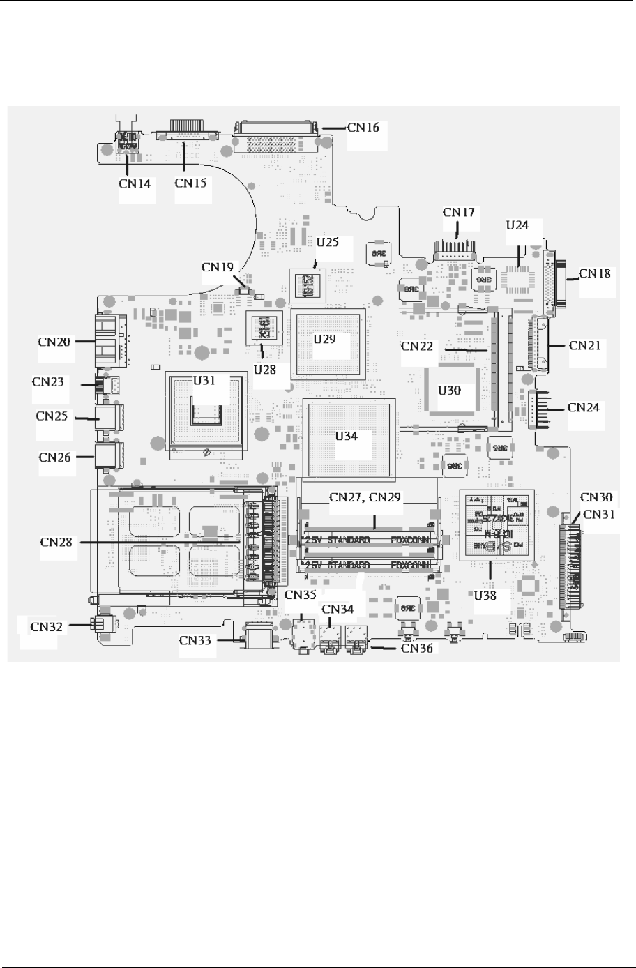
Mainboard Placement
Top View
4Chapter 1
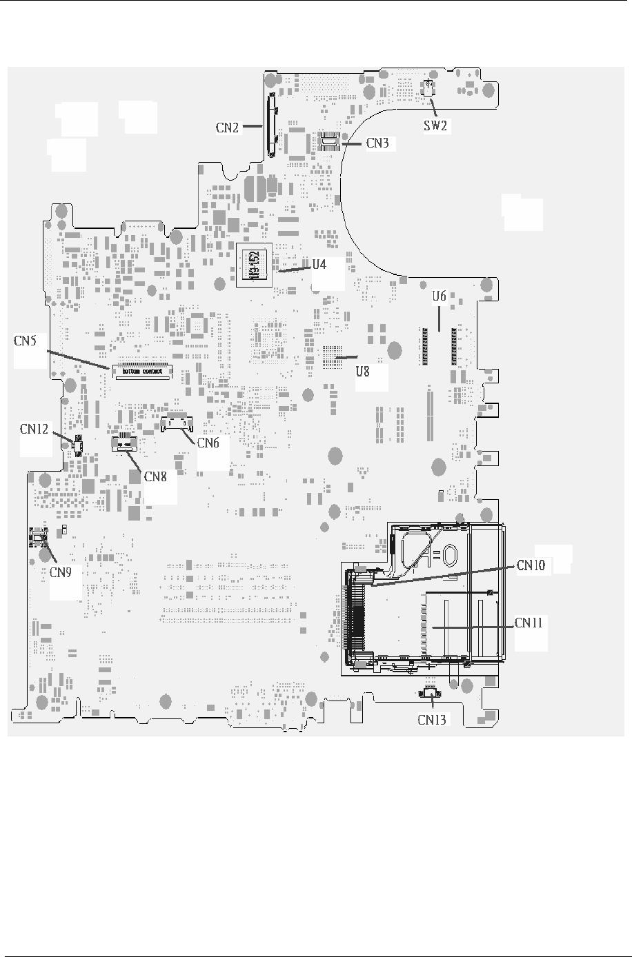
Rear View

Chapter 1 5
ITEM DESCRIPTION ITEM DESCRIPTION
CN2 LCD Connector CN14 DC JACK
CN3 LED board connector CN15 CRT connector
SW2 Lid switch CN16 Docking connector
CN10 express card connector CN17 Battery connector
CN11 4 IN 1 connector CN18 Fix ODD connector
CN13 Speaker connector CN21 Swap ODD connector
CN9 MD board connector CN24 2nd Battery connector
CN12 INT MIC connector CN30 PATA HDD connector
CN5 Keyboard connector CN31 SATA HDD connector
CN6 BT connector CN36 Line IN connector
CN8 TP connector CN34 MIC IN connector
U4 VGA RAM CN35 Line out/SPDIF
connector
U8 VGA RAM CN33 USB connector
U6 LAN transformer CN32 1394 connector
CN28 PCMCIA connector CN26 USB connector
CN25 USB connector CN23 S video connector
CN20 RJ45/RJ11 connector CN19 Fan connector
CN22 MINI PCI connector U31 CPU
U30 EC U29 VGA Chp
U34 North Bridge U38 South Bridge
U25 VGA RAM U28 VGA RAM
U24 BIOS ROM
6Chapter 1
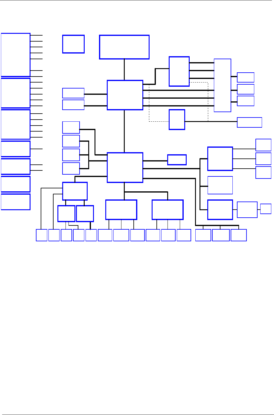
Block Diagram
INTEL Mobile_479 CPU
400/533MHZ DDR2
ATA 66/100
AC97
CLOCK GEN
AUDIO CODEC
Centrino
DDR2-SODIMM1
DDR2-SODIMM2
IDE-ODD
IDE - HDD
MODEM
RJ11
Page:27
Page:27
Page:27
Page:21
Page:21
Page:9~10
Page:9~10
ICS954201
Page : 3 , 4
Page : 5 ~ 8
Page : 18 ~ 20
Page : 2
Page:28
LINE
OUT
ALVISO
ICH6-M
609 BGA
DMI I/F
Page : 29
Page:30Page:30
Touchpad
KBC(97551)
Keyboard
DOCKING
Page:33
DOTHAN
CELEROM-M
M26P/M24P
Page : 11 ~ 14
ATI
64M /
128M
PCIE
TVOUT
EXT_LVDS
EXT_CRT
EXT_TV-OUT
INT_LVDS
INT_CRT
INT_TV-OUT
SWITCH
CIRCUIT
MEDIA BAY
Page:21
PCI7411
PCI BUS
MINI-USB
RJ45
TI
10/100/1G LAN
USB2,3,5
Page:25
PCMCIA
USB 2.0
Page : 22
Page: 23
Page : 22
Wireless LAN
Modem/LAN
Page: 24
SYSTEM 3
USB PORT
USB4
Page: 22
Page:26
MINI-PCI
BROADCOM
CONEXANT
20493-21
MAX9755
Page:28
AMP
20468-31
SPEKER
Page:28Page:27
LINE
IN
Page:27
MIC IN
CONEXANT
PS2
HOST BUS 400MHz
LPC
NS
SIO (87383)
NS
Page : 31
Page:31
IrDA
Page:33
DOCKING
Print Port
Page:33
DOCKING
COM Port
LVDS
RGB
Page : 22
DOCKING 2
USB PORT
USB0,1
PCMCIA+1394
+3 IN 1
1394
Page: 24
3 IN 1
Page: 23
4401 / 5705M TRANSFORMER
BOTHHAND
ICS
5V / 3.3V / 12V
Page : 35
5VPCU
3V_ALWAYS
+12V
3V_S5
+5V
3VSUS
5VSUS
1.8V / 0.9V
Page : 36 Page:16
TV-OUT
LVDS
CRT
Page:16
Page:17
Page : 37
1.5V / 1.05V / 1.8V
SMDDR_VTERM
+2.5V
2.5VSUS
+1.8V
MVREF_DM
AGP_VCC (+1.5V)
+1.5V
1.2VCCT
1.5V_S5
VTT
VCC_CORE
Page : 34
CPU CORE
+1.2V
Page : 38
VGA_CORE
2.5V_VGA
Page : 39
BATTERY
CHARGER
Page : 40
BATTERY
SELECT
CRANE2 ( ZL3 )
PCI ROUTING TABLE
REQ0# / GNT0#
REQ2# / GNT2#
REQ1# / GNT1#
IDSEL
AD24
AD19
AD17
INTERUPT
INTA#
INTB# , INTD#
INTC#,INTD#,INTA#
DEVICE
BROADCOM LAN
MINI-PCI
TI 7411
1257 BGA
DVI
Page:15
CH7307
Page:26
SATA - HDD
Page:21
SATA
DOCKING/DVI
NEW CARD
PCIE
Page : 32
Page: 33
REV.C
400/533MHZ DDR2
HOST BUS 533MHz
Chapter 1 7
Outlook View
A general introduction of ports allow you to connect peripheral devices, as you would with a desktop PC.
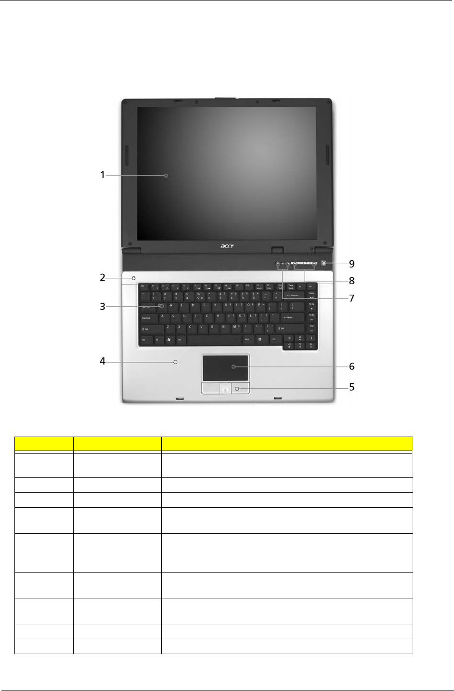
Open View
#Item Description
1 Display screen Also called Liquid-Crystal Display (LCD), displaying computer
output.
2 Microphone Internal microphone for sound recording.
3 Keyboard Inputs data into your computer.
4 Palmrest Comfortable support area for your hands when you use the
computer.
5 Click buttons
(Left, center and
right)
The left and right buttons function like the left and right mouse
buttons; the center button serves as a 4-way scroll button.
6 Touchpad Touch-sensitive pointing device which functions like a
computer mouse.
7 Status indicators Light-Emitting Diodes (LEDs) that turn on and off to show the
status of the computer’s functions and components.
8 Launch keys Buttons for launching frequently used programs.
9 Power button Turns the computer on and off.
Just for Starters...
# Item Description
8Chapter 1
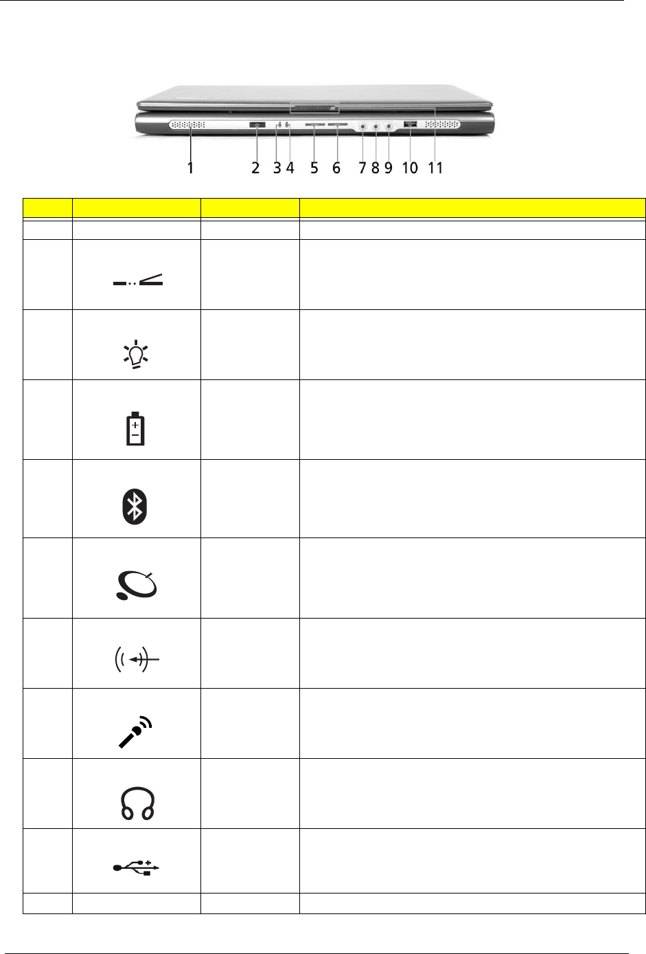
Front Panel
#Icon Item Description
1 N/A Speakers Left and right speakers deliver stereo audio output.
2 CIR Receiver Receives remote control infrared signals.
3 Power indicator Lights when the computer is on.
4 Battery indicator Lights when the battery is being charged.
5 Bluetooth
communication
button/indicator
Press to enable/disable Bluetooth function. Lights to indicate
the status of Bluetooth communications. (for TM4600 only)
6Wireless
communications
button/indicator
Press to enable/disable Wireless function. Lights to indicate
the status of wireless LAN communications. (manufacturing
option)
7 Line-in jack Accepts audio line-in devices (e.g., audio CD player, stereo
walkman).
8 Mic-in jack Accepts inputs from external microphones.
9 Speaker-Out /
Line-Out/
Headphone jack
Connects to audio line-out devices (e.g., speakers,
headphones).
10 USB 2.0 port Connects to Universal Serial Bus (USB) 2.0 devices (e.g.,
USB mouse, USB camera).
11 N/A Latch Locks and releases the lid.
"Launch keys" on page 10
# Icon Item Description
# Item Description
"Launch keys" on page 10
# Icon Item Description
# Item Description
"Launch keys" on page 10
# Icon Item Description
# Item Description
"Launch keys" on page 10
# Icon Item Description
# Item Description
"Launch keys" on page 10
# Icon Item Description
# Item Description
"Launch keys" on page 10
# Icon Item Description
# Item Description
"Launch keys" on page 10
# Icon Item Description
# Item Description
"Launch keys" on page 10
# Icon Item Description
# Item Description
"Launch keys" on page 10
# Icon Item Description
# Item Description
# Item Description
# Icon Item Description
# Icon Item Description
Chapter 1 9
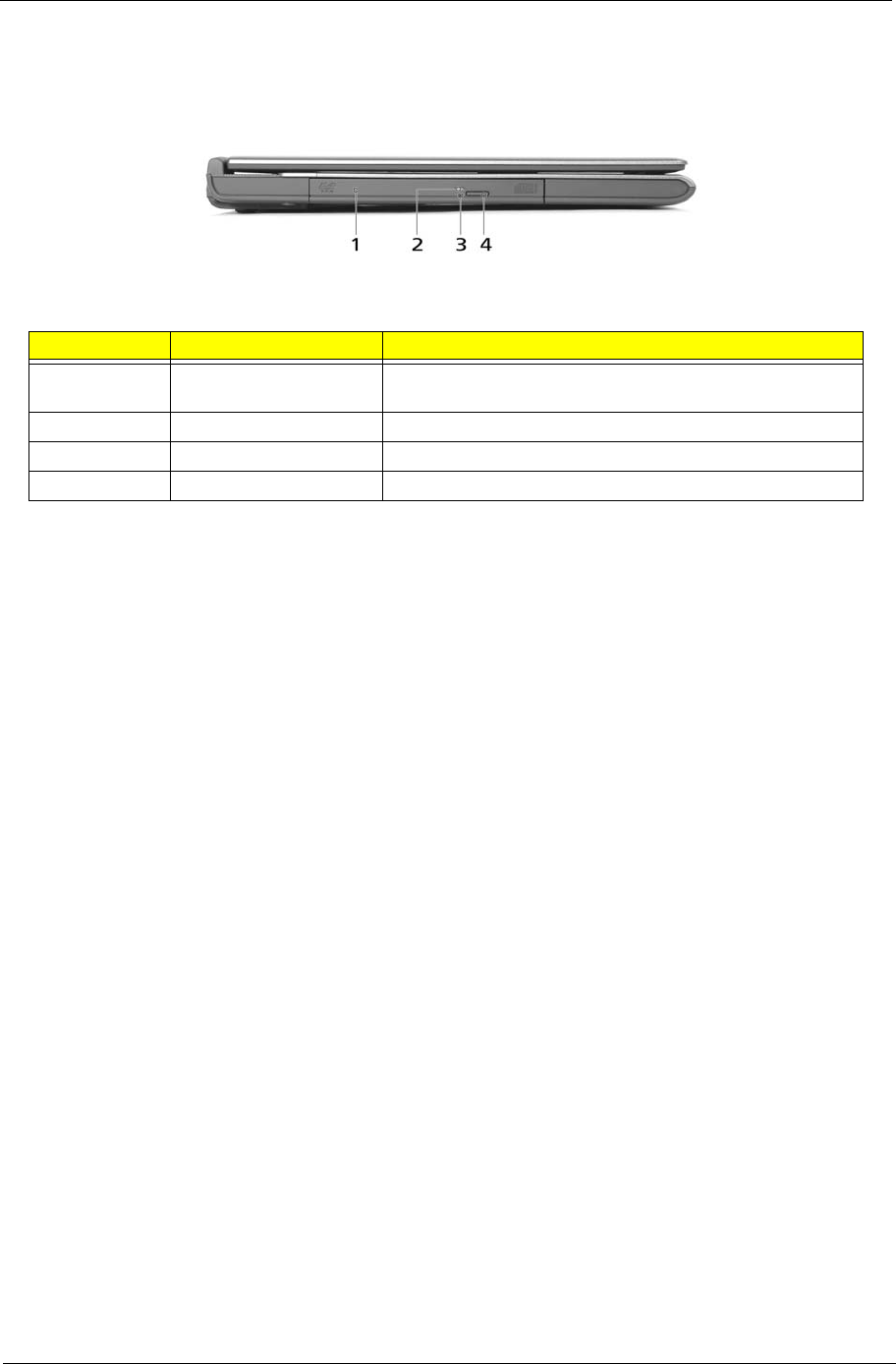
Left View
NOTE: The positions of the AcerMedia indicator, eject button and emergency eject hole may differ depending
on the optical drive module installed.
#Item Description
1 Optical drive Internal optical drive; accepts CDs or DVDs depending on
the optical drive type.
2 LED indicator Lights up when the optical drive is active.
3 Emergency eject hole Ejects the optical drive tray when the computer is turned off
4 Optical drive eject button Ejects the optical drive tray from the drive.
Note
# Item Description
# Icon Item Description
10 Chapter 1
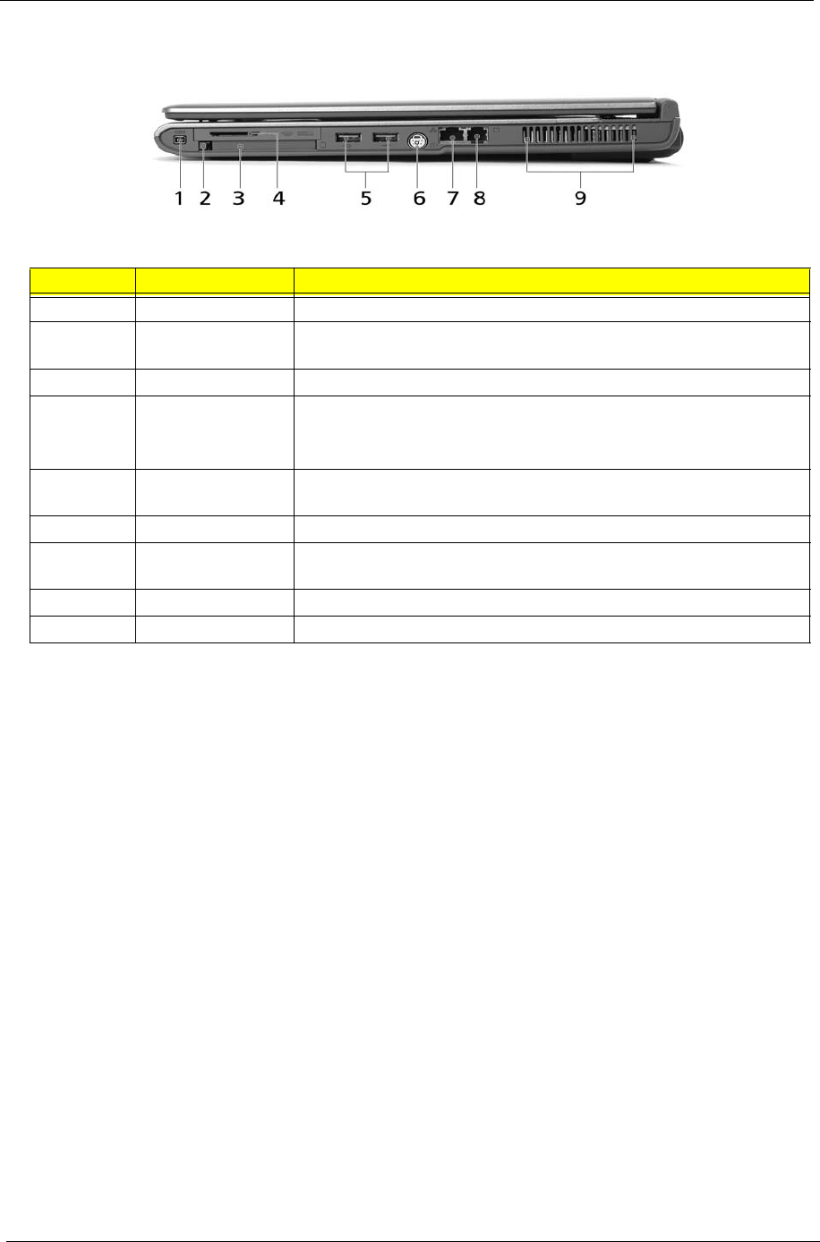
Right View
#Item Description
1 IEEE 1394 port Connects to IEEE 1394 devices.
2 PC Card slot eject
button
Ejects the PC Card from the slot.
3 PC Card slot Connects to one Type II CardBus PC Card.
4 4-in-1 card reader
(for TM4600 only)
Accepts MS, MMC, MS PRO and SD card.
Note: The 4-in-1 card reader is a manufacturing option, subject to
configuration. Only one card can operate at any given time.
5 Two USB 2.0 ports Connect to Universal Serial Bus (USB) 2.0 devices (e.g., USB mouse,
USB camera).
6 S-video port Connects to a television or display device with S-video input.
7 Network jack Connects to an Ethernet 10/100/1000-based network (for selected
models).
8 Modem jack Connects to a phone line.
9 Ventilation slots Enable the computer to stay cool, even after prolonged use.
# Item Description
Note:
Chapter 1 11
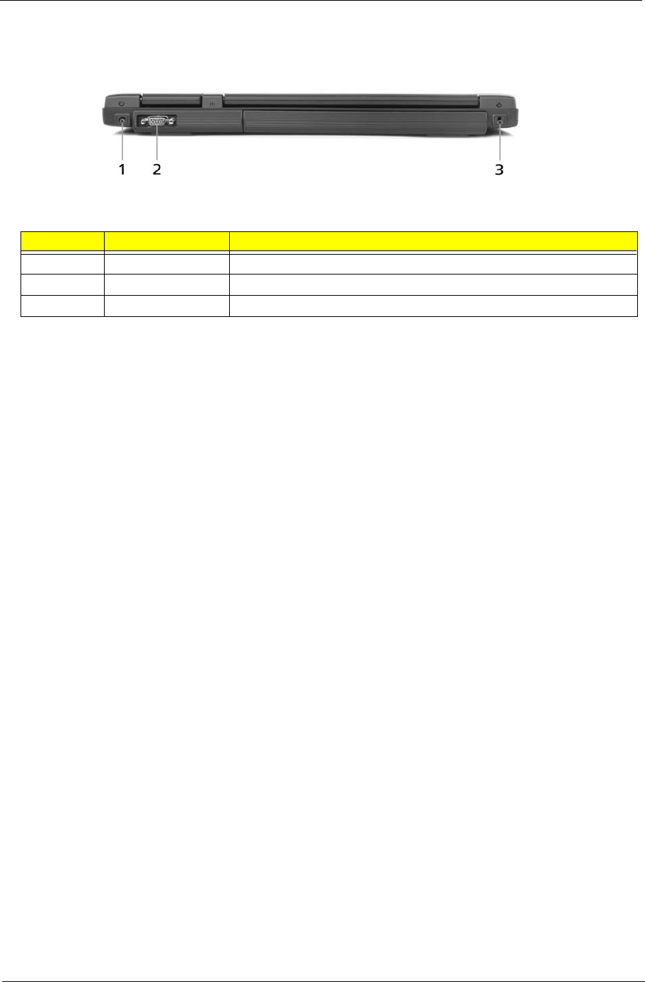
Rear View
#Item Description
1 Power jack Connects to an AC adapter.
2 External display port Connects to a display device (e.g., external monitor, LCD projector).
3 Security keylock Connects to a Kensington-compatible computer security lock.
# Item Description
# Item Description
12 Chapter 1
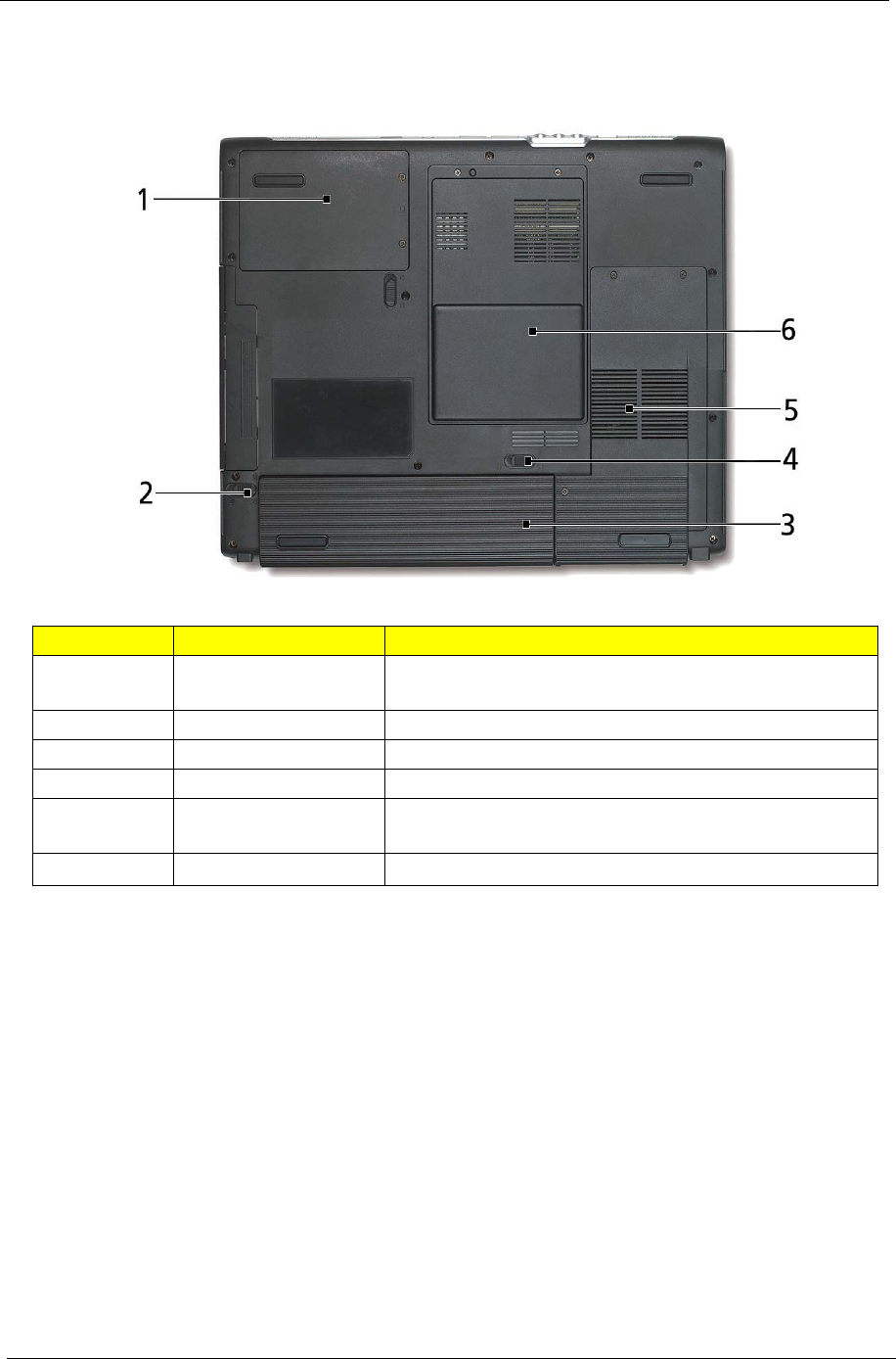
Bottom View
#Item Description
1 Hard disk bay Houses the computer's hard disk
(secured by a screw).
2 Battery release latch Unlatches the battery to remove the battery pack.
3 Battery bay Houses the computer's battery pack.
4 Battery lock Locks the battery in place.
5 Cooling fan Helps keep the computer cool.
NOTE: Do not cover or obstruct the opening of the fan.
6 Memory compartment Houses the computer's main memory a Mini PCI Card.
# Item Description
Note
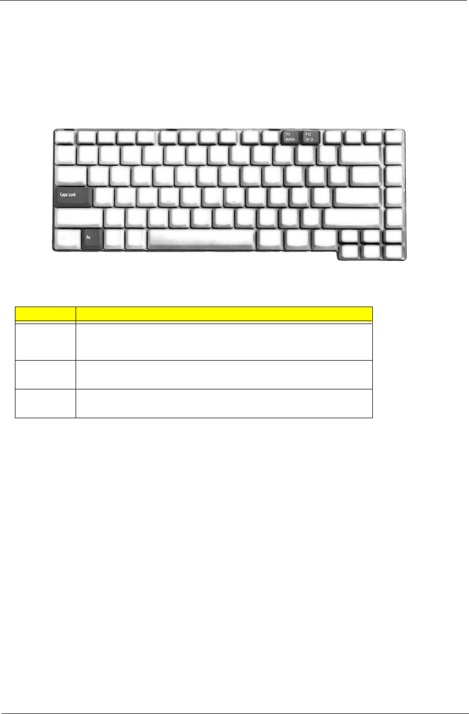
Chapter 1 13
Using the Keyboard
The full-sized keyboard includes an embedded numeric keypad, separate cursor keys, two Windows keys and
twelve function keys.
Lock keys
The keyboard has four lock keys which you can toggle on and off.
The computer features three lock keys, each with its own status indicator light.
NOTE: Scroll Lock doesn’t work in all applications. Toggle on and off by pressing the Fn+F12 keys
simultaneously.
Lock Key Description
Caps Lock When Caps Lock is on, all alphabetic characters are typed in
uppercase. Toggle on and off by pressing the Caps Lock key on the
left side of the keyboard.
Num lock
<Fn+F11>
When Num Lock is on, the embedded numeric keyboard can be
used. Toggle on and off by pressing the Fn+tkeys simultaneously.
Scroll lock
<Fn+F12>
When Scroll Lock is on, the screen toggles up or down one line
at a time when the up and down cursor control keys are pressed.
Lock key Description
Caps
Lock
Fn F10
Fn F11
Fn F12
14 Chapter 1
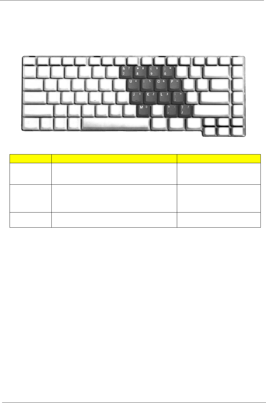
Embedded Numeric Keypad
The embedded numeric keypad functions like a desktop numeric keypad. It is indicated by small characters
located on the right-hand side of the keycaps.
Desired action Num Lock on Num Lock off
Number keys on
embedded
keypad
Type numbers in a normal manner
Cursor-control
keys on
embedded
keypad
Hold Shift while using cursor-control keys. Hold Fn while using cursor-control
keys.
Main keyboard
keys
Hold Fn while typing letters on embedded keypad. Type the letters in a normal
manner.
Desired action Num Lock on Num Lock off
Fn
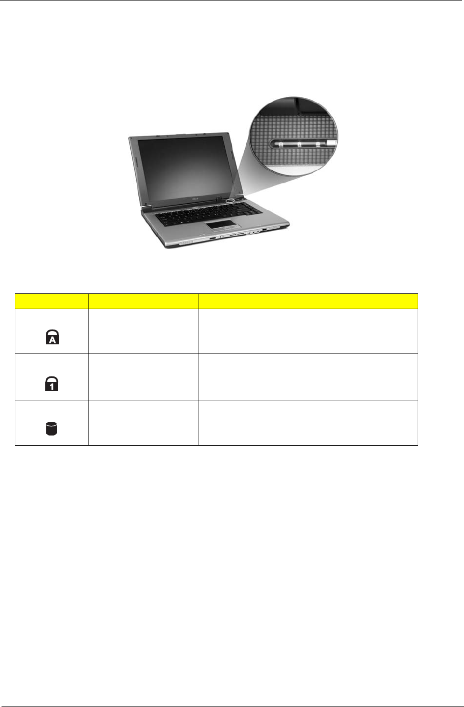
Chapter 1 15
Indicators
Your computer provides an array of three indicators located above the keyboard, in addition to four
indicators positioned at the front of the palm rest area. These indicators show the status of the computer
and its componetns.
The three indicators located above the keyboard provide the following status information:
NOTE: The keypad lock must be turned on to use the embedded numeric keypad.
Icon Item Description
Caps Lock activity Lights when Caps Lock is activated.
Num Lock activiy Lights when Num Lock is activated.
Media activity Lights when the hard disk or optical drive is active.
Icon Function Description
16 Chapter 1
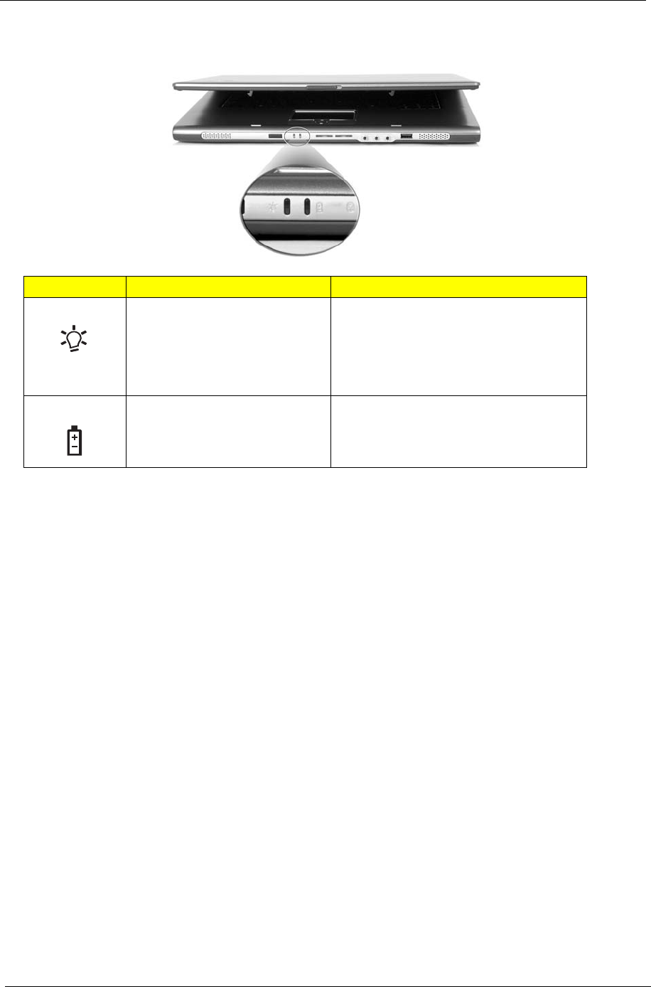
In addition, there are two indicators at the front panel. Even when the cover is closed, the state or features can
still be seen.
Icon Item Description
Power Lights when the computer is on.
1. Charging: the light shows amber
when the battery is charging.
2. Fully charged: light shows green
when in AC mode.
Battery indicator Lights when the battery is being charged.
Icon Function Description
Chapter 1 17
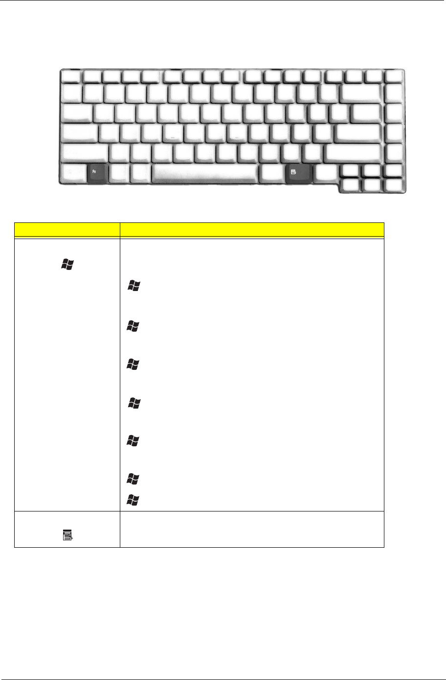
Windows Keys
The keyboard features two keys that perform Windows-specific functions.
Key Description
Windows logo key Pressed alone, this key has the same effect as clicking on the
Windows Start button; it launches the Start menu. It can also be
used with other keys to provide a variety of functions:
+ Tab (Activates the next Taskbar button)
+ E (Opens the My Computer window)
+ F1 (opens Help and Support)
+ F (opens the Find: All Files dialog box)
+ M (minimizes all windows)
+ j + M (undoes the minimize all windows action)
+ R (opens the Run dialog box)
Application key This key has the same effect as clicking the right mouse button; it
opens the application’s context menu.
Key Description
Tab
E
F
M
Shift M
R
18 Chapter 1
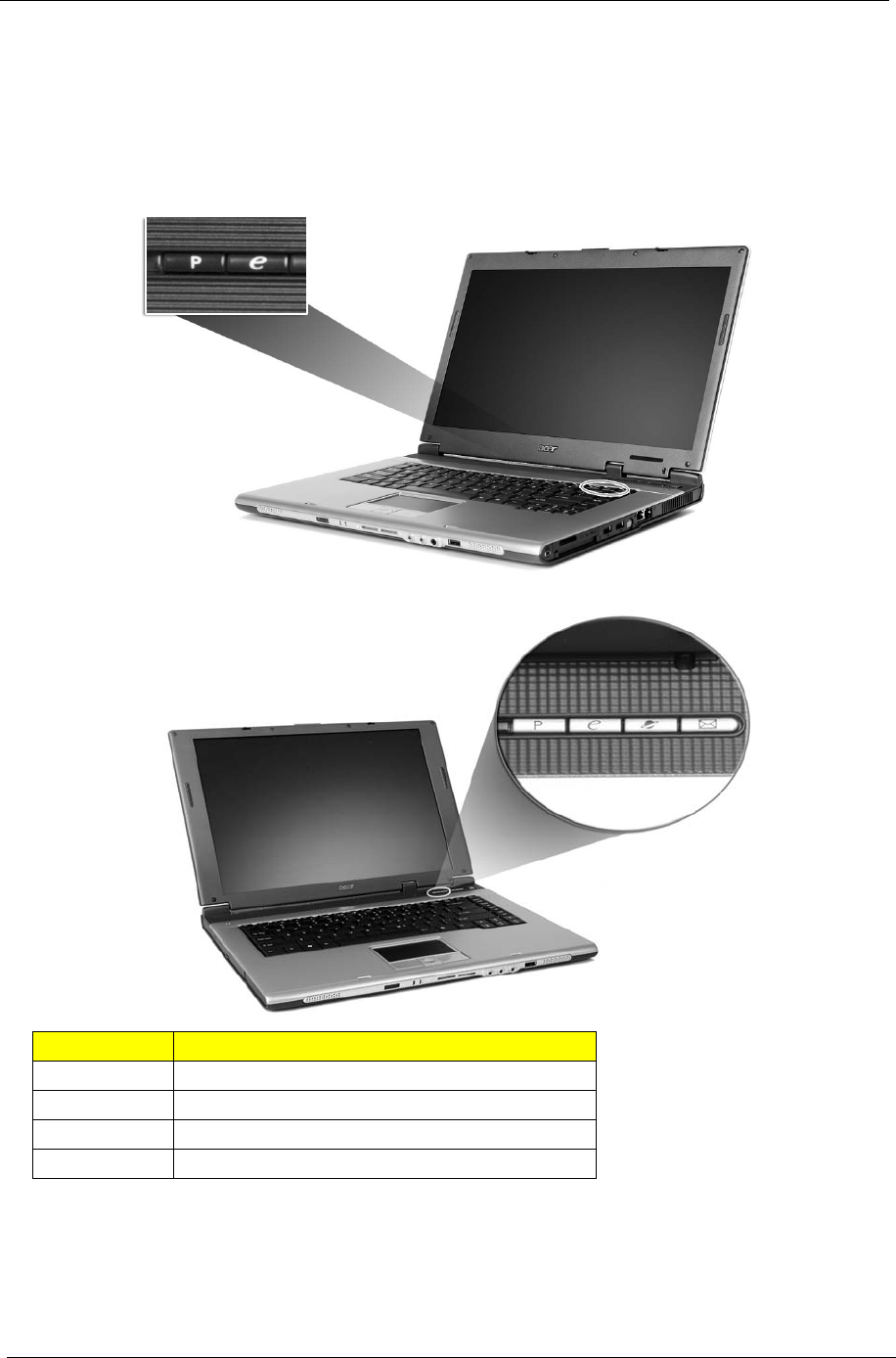
Launch Keys
Located above the keyboard are three buttons. The left-most button is the power button. To the right of the
power button are the two launch keys. They are designated as the Empowering Key and a programmable
button.
Launch Key Default Application
e Acer eManager application (user-programmable)
p User-programmable
Mail Email application (User-programmable)
Web browser Internet browser application (User-programmable)
Launch key Default application
Euro
Alt Gr Euro
dollar
Alt Gr dollar
Note:
Launch key Default application
Chapter 1 19
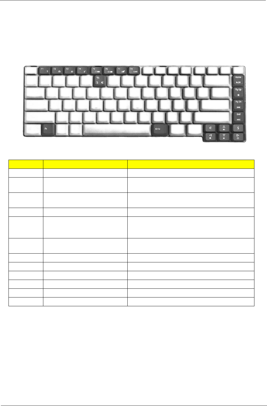
Hot Keys
The computer employs hot keys or key combinations to access most of the computer’s controls like screen
brightness, volume output and the BIOS Utility.
To activate hot keys, press and hold the <Fn> key before pressing the other key in the hot key combination.
Hot Key Function Description
Fn-F1 Hot key help Displays help on hot keys.
Fn-F2 Acer eSetting Launches the Acer eSetting in the Acer eManager
set by the Acer Empowering Key.
Fn-F3 Acer ePowerManagement Launches the Acer ePowerManagement in the Acer
eManager set by the Acer Empowering Key.
Fn-F4 Sleep Puts the computer in Sleep mode.
Fn-F5 Display toggle Switches display output between the display screen,
external monitor (if connected) and both the display
screen and external monitor.
Fn-F6 Screen blank Turns the display screen backlight off to save power.
Press any key to return.
Fn-F7 Touchpad toggle Turns the internal touchpad on and off.
Fn-F8 Speaker toggle Turns the speakers on and off.
Fn+wVolume up Increases the sound volume.
Fn+yVolume down Decreases the sound volume.
Fn+xBrightness up Increases the screen brightness.
Fn+zBrightness down Decreases the screen brightness.
Fn
Hot key Icon Function Description
Fn-F1
Fn-F2
Fn-F3
Fn-F4
Fn-F5
Fn-F6

20 Chapter 1
Special Keys
You can locate the Euro symbol and US dollar sign at the upper-centerand/or bottom-right of your keyboard.
To t y p e :
1. Open a text editor or word processor.
2. Either directly press the Euro symbol at the bottom-right of the keyboard, or hold Alt Gr and then press
the Euro symbol at the upper-center of the keyboard.
The US dollar sign
1. Open a text editor or word processor.
2. Either directly press the dollar sign at the bottom-right of the keyboard, or hold Shift and then press the
dollar sign at the upper-center of the keyboard.
Fn-F7
Fn-F8
Fn-
Fn-
Fn-
Fn-
Fn-Home
Hot key Icon Function Description
Chapter 1 21
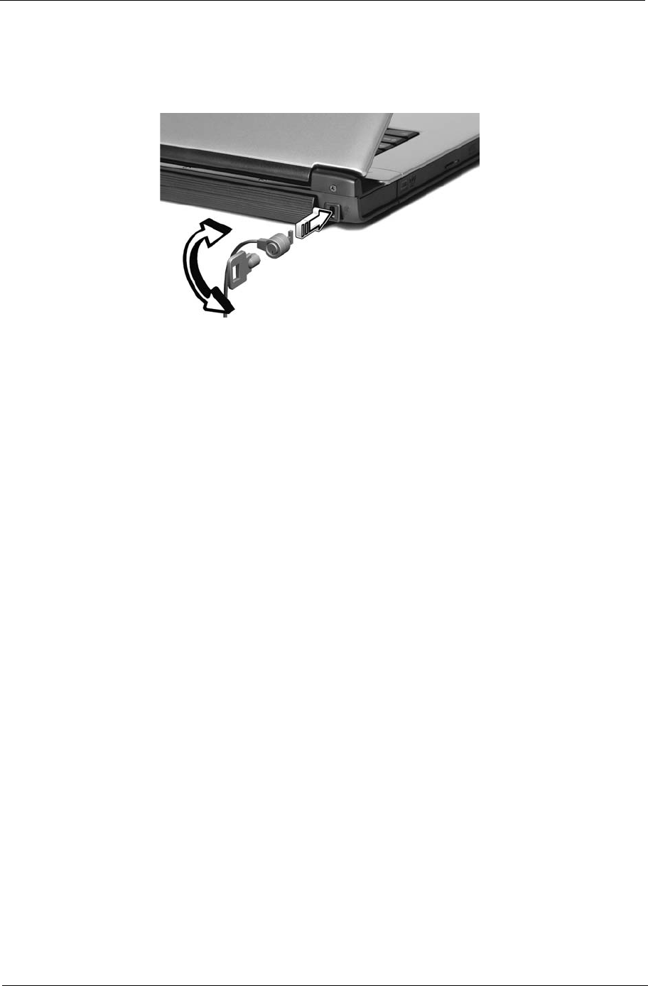
Using a computer security lock
A security keylock notch, located on the rear of the computer, lets you connect a Kensington-compatible
computer security lock.
Wrap a computer security lock cable around an immovable object such as a table or handle of a locked
drawer. Insert the lock into the notch and turn the key to secure the lock. Some keyless models are also
available.
22 Chapter 1
Using System Utilities
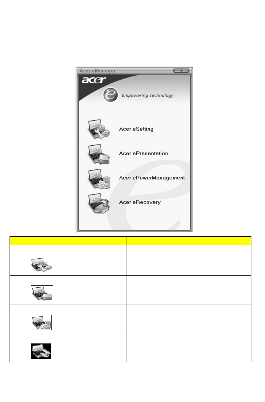
Acer eManager
Innovative Acer eManagement software is designed for easy access to frequently used functions. At the press
of Acer Empowering Key, the Acer eManager user interface appears, featuring four main settings -- Acer
eSetting, Acer ePresentation, Acer ePowerManagement and Acer eRecovery.
Icon Item Description
Acer eSetting It is an easy way to manage the settings and security
of your PC.
Acer ePresentation It takes the hassle out of making presentations.
Acer
ePowerManagement
It provides a central location from where to control all
your PC’s power schemes and maximise battery life.
Acer eRecovery It backs up your files preventing data loss in the
event of a system crash.
“Launch keys” on page 20
Acer eSetting
Acer ePresentation
Acer ePowerManagement
Acer eRecovery
“Launch keys” on page 20
Acer eSetting
Acer ePresentation
Acer ePowerManagement
Acer eRecovery
“Launch keys” on page 20
Acer eSetting
Acer ePresentation
Acer ePowerManagement
Acer eRecovery
“Launch keys” on page 20
Acer eSetting
Acer ePresentation
Acer ePowerManagement
Acer eRecovery
Chapter 1 23
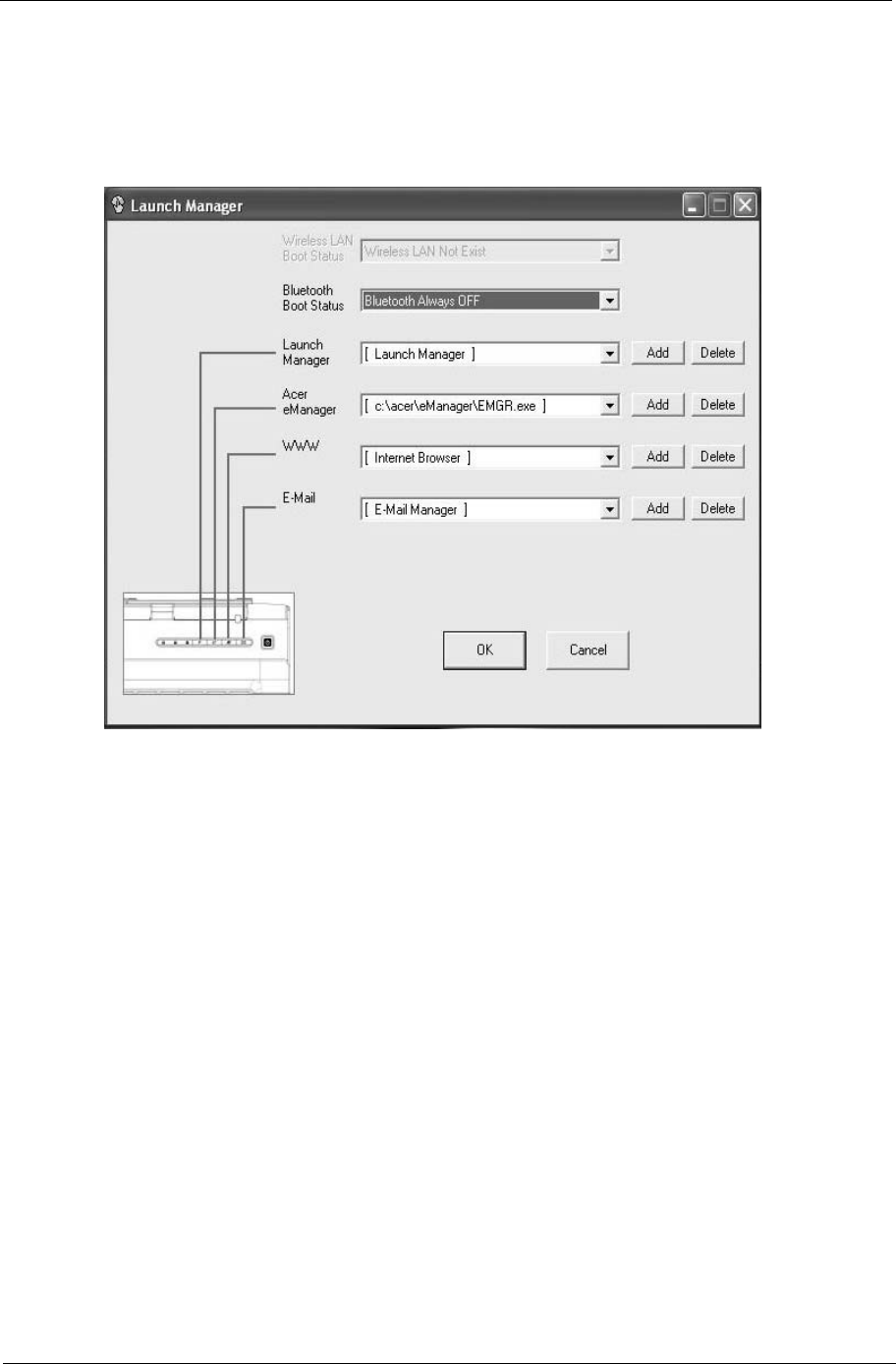
Launch Manager
Launch Manager allows you to set the two launch keys located above the keyboard.
You can access the Launch Manager by clicking on Start, All Programs, and then Launch Manager to start
the application.
Start
All Programs Launch Manager
24 Chapter 1
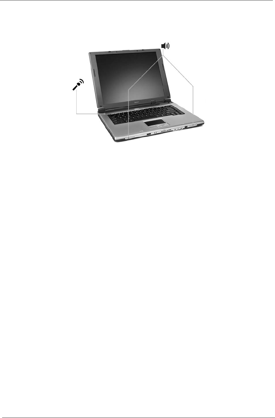
Audio
The computer comes with 16-bit high-fidelity AC'97 stereo audio, and dual stereo speakers.
Adjusting the Volume
Adjusting the volume on the computer is as easy as pressing some buttons.
“Hot keys” on page 17
Chapter 1 25
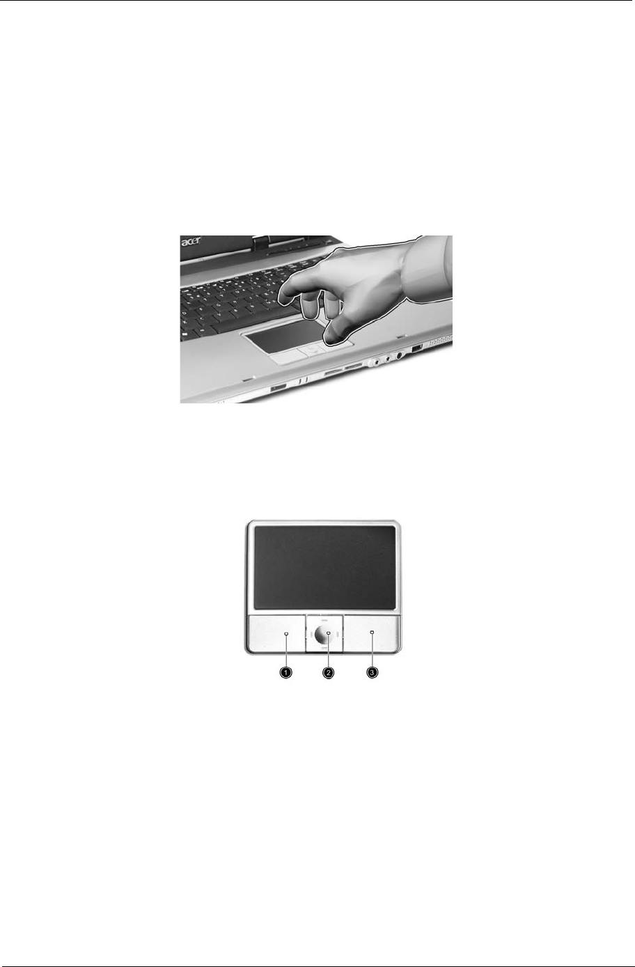
Touchpad
The build-in touchpad is a PS/2 compatible pointing device that senses movement on its surface.
The cursor responds to your finger movements on the touchpad. In addition, the two click buttons provide
the same functionality as a computer mouse, while the scroll key enables easy up and down scrolling in
documents and web pages.
The touchpad is located in the middle of the palm rest area, providing maximum comfort and efficiency.
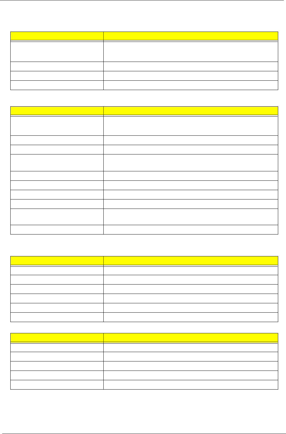
Touchpad Basics
Use the touchpad as follows:
TMove your finger across the touchpad to move the cursor.
TPress the left (1) and right (3) buttons located on the edge of the touchpad to do selection and
execution functions. These two buttons are similar to the left and right buttons on a mouse.
Tapping on the touchpad is the same as clicking the left button
TUse the 4-way scroll (2) button to scroll up or down and move left or right a page. This button
mimics your cursor pressing on the right scroll bar of windows applications.

26 Chapter 1
NOTE: Keep your fingers, as well as the surface of the touchpad dry and clean. The touchpad is sensitive to
your finger movements: the lighter the touch, the better the response. Tapping hard will not increase the
touchpad’s responsiveness.
Function Left Button Righ Button Tap
Execute Click twice quickly Tap twice (at the
same speed as
double-clicking the
mouse button)
Select Click once Tap once
Drag Click and hold.
Then slide your
finger across the
touchpad to drag
the cursor over the
selection.
Tap twice quickly.
On the second tap,
slide your finger
across the
touchpad to drag
the cursor over the
selection.
Access
context
menu
Click once

Chapter 1 27
Ejecting the optical (CD or DVD) drive tray
To eject the optical drive tray when the computer is turned on, press the drive eject button.
When the power is off, you can eject the drive tray using the emergency eject hole.
j
28 Chapter 1
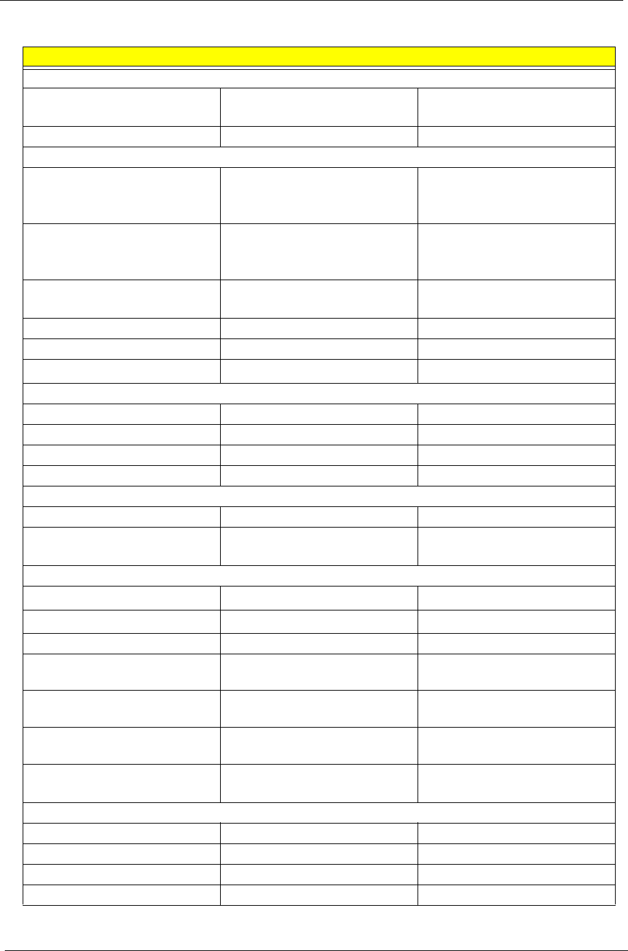
Hardware Specifications and Configurations
System Board Major Chips
Processor
Item Specification
CPU type Intel® Pentium® M Processor at 1.5 ~2.13 GHz or higher
Intel® Celeron® M Processor at 1.3~1.5 GHz or higher
CPU package uFPGA 478
CPU core voltage Depend on DVI
CPU I/O voltage 1.2V
Item Controller
System core logic Intel® 915PM / ICH6-M
Intel® 915GM / ICH6-M
Super I/O controller KBC (97551), LPC interface
Audio controller Conexant Codec
Video controller ATI M24P
UMA
Hard disk drive controller ICH6-M
Keyboard controller KBC 97551
IrDA controller SIO 87383
DVI controller CH7307
PCMCIA/ card reader / 1394
controller
TI PCI7411
DDR-soDIMM controller 915PM/915GM
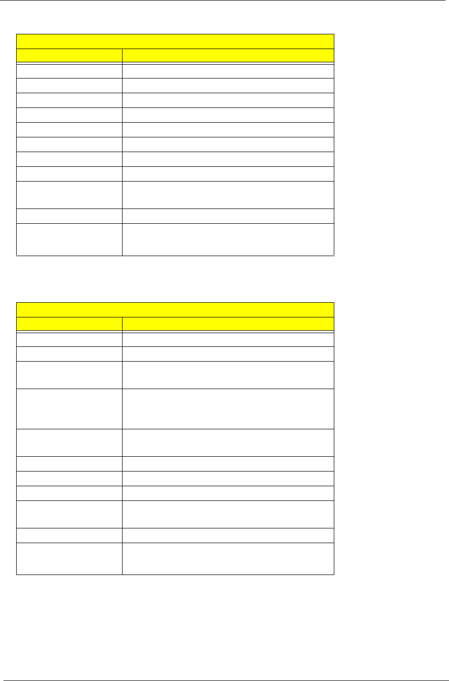
BIOS
Item Specification
BIOS vendor Phoenix
BIOS Version Phoenix First BIOS
BIOS ROM type Flash ROM
BIOS ROM size 512KB
BIOS package 32 lead of TSSOP
BIOS password control Set by setup manual
Item Specification
Cache controller Built-in CPU
Cache size 2 MB
1st level cache control Always enabled
2nd level cache control Always enabled
Cache scheme control Always enabled
Chapter 1 29
.
.
VGA
System Memory
Item Specification
Memory controller 915PM/915GM
Memory size 256MB/512MB
DIMM socket number 2
Supports memory size per slot 1024 MB
Supports maximum memory size 2GB (with dual soDIMM modules)
Supports DIMM type DDRII SDRAM Standard
Supports DIMM Speed 400/533 MHz
Supports DIMM voltage 1.8V
Memory module combinations You can install memory modules in any combinations as long as
they match the above specifications.
LAN Interface
Item Specification
Supports LAN protocol 10/100/1000 Mbps Fast Ethernet connection
(for Aspire 1690)
10/100 Mbps Fast Ethernet connection
(for Aspire 3510)
LAN connector type RJ45
Wireless LAN InviLink. 802.11b/g dual-band tri-mode
Wireless
or 802.11 a/b/g dual-band tri-mode Wireless
LAN connector location Right side
Modem/Bluetooth Interface
Item Specification
Data modem data baud rate (bps) 56K ITU
Supports modem/bluetooth protocol V.90/V.92 AC-Link modem with PTT
approval
Wake-on-Ring ready
Modem connector type RJ11
Modem connector location Right side
Notice Discreat UMA
Chipset for suitable VGA type 915PM 915GM
30 Chapter 1
Audio Port
USB Port
Item Specification
USB compliancy level 2.0
OHCI USB 2.0
Number of USB port 3
Location Right Side *2
Front Side *1
Item Specification
Audio Controller AC’ 97 Codec
Audio onboard or optional Built-in
Mono or Stereo Stereo
Resolution 20 bit stereo Digital to analog converter
18 bit stereo Analog to Ditial converter
Compatibility Microsoft PC99/2100, AC97 2.3 & WHQL/WLP2.0
Mixed sound source CD
Sampling rate 48 KHz
Internal microphone Yes
Internal speaker / Quantity Yes / 2
PCMCIA Port
Item Specification
PCMCIA controller PCI7411
Supports card type Type II
Number of slots One type-II
Access location Right Side
Supports ZV (Zoomed Video) port No
Supports 32 bit CardBus Yes
Keyboard
Item Specification
Keyboard controller KBC 97551
Keyboard vendor & model name Standard keyboard w launch button embeded
Total number of keypads T88-89 keys Acer Fine TouchTM
keyboard
Touchpad with 4-way integrated scroll button Yes
Chapter 1 31
12 function keys Tfour cursor keys
Ttwo Windows keys
THotkey controls
Tembedded numberic keypad
Tinternational language support (for
TM4600/TM4100)
Four easy-launch buttons TInternet browser
Temail with LED
TEmpowering key
Tone user-programmable button
Two front access LED buttons TWLAN LED button
TBluetooth LED button
Battery
Item Specification
Vendor & model name Panasonic/Sanyo
Battery Type Li-ion
Pack capacity 65Wh
Cell voltage 3.7V/cell/2000mAh High discharge rate
Number of battery cell 8-cell(65W)
4-cell(32W)
Package configuration
Pin 1
Pin 2
BATT+: Battery+, Battery Positive Terminal
Pin 3 ID : Identify Pin (Note 1)
Pin 4 B/I : Battery-In Pin
Pin 5 TS : Connect to Thermister
Pin 6 SMD : SMBus data interface I/O pin
Pin 7 SMC : SMBus clock interface I/O pin
Pin 8
Pin 9
GND : Battery Negative Terminal
Keyboard
Item Specification
32 Chapter 1
LCD :15.4" WXGA LCD
Item Specification
Vendor & model name CMO
N154I1-L09
LPL
LP154W01-
A5
Hitachi
TX39D85V
C1FAA
Samsung
LTN154X3-
L01
QDI
QDI15TL02-
01
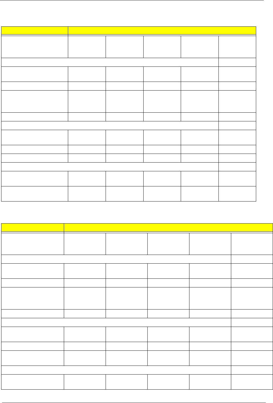
Mechanical Specifications
LCD display area
(diagonal, inch)
15.4” 15.4” 15.4” 15.4” 15.4”
Display technology TFT TFT TFT TFT TFT
Resolution WXGA
(1280*800)
WXGA
(1280*800)
WXGA
(1280*800)
WSXGA
(1280*800)
WSXGA
(1280*800)
Supports colors 16.7 million 16.7 million 16.7 million 16.7 million 16.7 million
Optical Specification
Brightness control keyboard
hotkey
keyboard
hotkey
keyboard
hotkey
keyboard
hotkey
keyboard
hotkey
Contrast controlNoNoNoNoNo
Suspend/Standby control Yes Yes Yes Yes Yes
Electrical Specification
Supply voltage for LCD
display (V)
3.3 3.3 3.3 3.3 3.3
Supply voltage for LCD
backlight (Vrms)
785 785 730 735 735
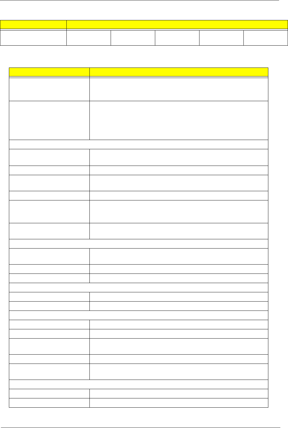
LCD: 15” XGA
Item Specifications
Vendor & model name AU
B150XG02
V.2
LG
LP150X08-A3
Samsung
LTN150XB-
L03-C00
Hitachi
TX38D81VC1
CAB Rev.C
CMO
N150X3-L07
Mechanical Specifications
LCD display area
(diagonal, inch)
15” 15” 15” 15” 15”
Display technology TFT TFT TFT TFT TFT
Resolution XGA
(1024*768)
XGA
(1024*768)
XGA
(1024*768)
XGA
(1024*768)
XGA
(1024*768)
Supports colors 16.7 million 16.7 million 16.7 million 16.7 million 16.7 million
Optical Specification
Brightness control keyboard
hotkey
keyboard
hotkey
keyboard
hotkey
keyboard
hotkey
keyboard
hotkey
Contrast control No No No No No
Suspend/Standby
control
Yes Yes Yes Yes Yes
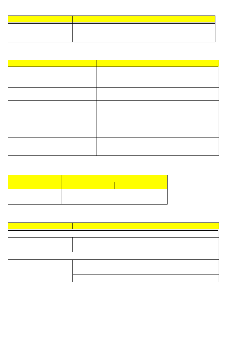
Electrical Specification
Supply voltage for LCD
display (V)
3.3 3.3 3.3 3.3 3.3
Chapter 1 33
Supply voltage for LCD
backlight (Vrms)
785 785 730 735 735
AC Adapter
Item Specification
Vendor & model name Delta 3-pin, 19V 3.95A, 64W
Hipro 3-pin, 19V 3.95A, 65W
Lite-on 3-pin, 19V 3.95A, 60W
Details 65W Li-ion battery pack (8-cell)
T4-hour battery life (support intel GFX)
T3-hour battery life (support ATI X600)
T1.5-hour quick-charge, 3.5-hour charge-in use
Input Requirements
Maximum input current (A,
@100Vac, full load)
1.8A max@3.5A/100Vac and 240 Vac
Nominal frequency (Hz) 47 - 63
Frequency variation range
(Hz)
47 - 63
Nominal voltages (Vrms) 90 - 264
Inrush current The maximum inrush current will be less than 50A and 100A when
the adapter is connected to 100Vac(60Hz) and 240Vac(50Hz)
respectively.
Efficiency High efficiency 85% minimum, at 100~240Vac AC input, full load,
warm-up condition.
Output Ratings (CV mode)
DC output voltage Offers constant voltage 19.0V output source with 150W max output
power capacity.
Noise + Ripple 300mvp-pmax (20MHz bandwidth) for resistor load
Output current 0 A (min.) 3.5A (max.)
Output Ratings (CC mode)
DC output voltage 18.0 ~ 20.0
Constant output 7.9A
Dynamic Output Characteristics
Start-up time 3 sec. (@115 Vac and 230Vac full load)
Hold up time 5ms min. (@115 Vac input, full load)
Over Voltage Protection
(OVP)
25V
Short circuit protection Output can be shorted without damage, and auto recovery
Electrostatic discharge
(ESD)
15kV (at air discharge)
8kV (at contact discharge)
Dielectric Withstand Voltage
Primary to secondary 4242 Vdc for 1 second-
Leakage current 60uA at 240Vac/60Hz
LCD: 15” XGA
Item Specifications
34 Chapter 1
Regulatory Requirements 1. FCC class B requirements (USA)
2. VDE class B requirements (German)
3. VCCI classII requirements (Japan)
Power Management
ACPI Mode Power Management
Mech. Off (G3) All devices in the system are turned off completely.
Soft Off (G2/S5) OS initiated shutdown. All devices in the system are turned
off completely.
Working (G0/S0) Individual devices such as the CPU and hard disk may be
power managed in this state.
Sleeping State (S3) CPU Power Down
VGA Power Down
PCMCIA Suspend
Audio Power Down
Hard Disk Power Down
Super I/O Power Down
Sleeping State (S4) Also called Hibernate state. System saves all system
states and data onto the disk prior to power off the whole
system.
Dimensions and Weight
Item Details
Model Aspire 1690 Aspire 3510
Deminsions 360(W) x 273(D) x 27~32 (H)mm
Weight 6.6lbs (3kg)
Environmental Requirements
Item Specification
Temperature
Operating +5 ~ +35°C
Non-operating -20 ~ +65°C (storage package)
Humidity
Operating 20% ~ 80% without condensation
Altitude Operating sea level 0 to 10,000ft
Storage sea level 0 to 40,000ft
AC Adapter
Item Specification
Chapter 1 35
TOSHIBA
Model Name MK4025GAS ,KA100A,
40GB
Pluto MK6025GAS
60GB
Pluto MK8025GAS,
8MB, 80GB
Data Storage Physical
Per drive, formatted 40.007GB 60.0116GB 80.012GB
Data Heads 2 4 4
Number of Disks 122
Logical Configuration
Heads 16 16 16
Cylinders 16,383 16,383 16,383
User Sectors/Track at
zone 0
63 63 63
Logical Blocks (LBA) 78,140,160 117,210,240 156,301,488
Data Transfer Rate
Max transfer rate to host 100MB/sec 100MB/sec 100MB/sec
Seek Time
Track-to-track 2ms 2ms 2ms
Average 12ms 12ms 12ms
Maximum 22ms 22ms 22ms
TOSHIBA
Nominal Power Requirements
Logic +5V( %) +5V( %) +5V( %)
Start 4.7watts 5.0watts 4.7watts
Seeking 2.6watts 2.9watts 2.6watts
Reading/Writing 2.3watts 2.5watts 2.3watts
Idle 0.9watts 1.05watts 0.9watts
Standby 0.25watts 0.25watts 0.25watts
Sleep 0.1watts 0.1watts 0.1watts
Other
Rotational Speed 4,200rpm 5,400rpm 4,200rpm
Average Latency 7.14ms 5.56ms 7.14ms
Interface ATA-2/3/4/5/6 ATA-5 ATA-2/3/4/5/6
Buffer 8MB 16MB 8MB
Physical & Environmental Specs
Dimensions/Weight:
Height 0.37" (9.5mm) 0.37" (9.5mm) 0.37"(9.5mm)
Width 2.75" (69.85mm) 2.75" (69.85mm) 2.75" (69.85mm)
Depth 3.94" (100mm) 3.94" (100mm) 3.94"(100mm)
Weight 3.35 oz (94g) 3.56 oz (101g) 3.49 oz (99g)
Ambient Temperature:
5±5±5±
36 Chapter 1
Operating 41 - 131 F (5 to 55 C) 41 - 131 F (5 to 55 C) 41 - 131 F (5 to 55 C)
Non-Operating -4 - 140 F (-20 to
60 C)
-4 - 140 F (-20 to
60 C)
-4 - 140 F (-20 to
60 C)
Shipping -40 - 158 F (-40 to
70 C)
-40 - 158 F (-40 to
70 C)
-40 - 158 F (-40 to
70 C)
Vibration and Shock
Operating Vibration 9.8 M/S2 (1.0G), 5 - 500
Hz
9.8 M/S2 (1.0G), 5 - 500
Hz
9.8 M/S2 (1.0G), 5 - 500
Hz
Operating Shock 200g 200g 200g
Non-Operating Shock 800g 800g 800g
Reliability Characteristics
Error Rates
Non-recoverable 1 in 1013 bits 1 in 1013 bits 1 in 1013 bits
Seek 1 in 106 seeks 1 in 106 seeks 1 in 106 seeks
Other
Preventive Maintenance None None None
MTTF (Power on hours) 300,000 300,000 300,000
Product Life 5 years or 20,000 power
ON hours
5 years or 20,000 power
ON hours
5 years or 20,000 power
ON hours
°° ° °° ° °° °
°°
°
°°
°
°°
°
°°
°
°°
°
°°
°

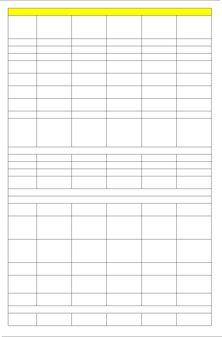
Chapter 1 37

38 Chapter 1

Chapter 1 39
HGST
Model
Name
Moraga+
HTS424040M9
AT00 13G1132,
40GB, 4200rpm
Moraga
IC25N060ATM
R04-0
08K0634,
60GB, 4200rpm
Moraga
IC25N080ATM
R04-0 08K635
80GB, 4200rpm
Moraga
HTS541060G9
AT00, 60GB,
5400rpm
Moraga
HTS541080G9
AT00, 80GB,
5400rpm
Configuration
Interface ATA-6 ATA-6 ATA-6 ATA-6 ATA-6
Capacity
(GB)1
40 60 80 60 80
Sector size
(bytes)
512 512 512 512 512
Recording
zones
16 16 16 16 16
Data heads
(physical)
23434
Data disks12222
Max. areal
density
(Gbits/
sq.inch)
70 70 70 70 86
Performance
Data buffer
(MB)
28888
Rotational
speed
(RPM)
4,200 4,200 4,200 5,400 5,400
Latency
average
(ms)
7.17.17.15.55.5
Media
transfer rate
(Mbits/sec,
max)
350 350 350 493 493
Interface
transfer rate
(MB/sec,
max)
100MB/sec
Ultra DMA
mode-5
100MB/sec
Ultra DMA
mode-5
100MB/sec
Ultra DMA
mode-5
100 Ultra DMA
mode-5
100 Ultra DMA
mode-5
Seek time (read, typical)
Average
(ms)
12 12 12 12 12
Track to
track (ms)
2.52.52.52.52.5
Full track
(ms
23 23 23 23 23
Power
Requirement +5VDC( %) +5VDC( %) +5VDC( %) +5VDC( %) +5VDC( %)5±5±5±5±5±
40 Chapter 1
Dissipation
Startup
current
(peak, max.)
4.7 W4.7 W4.7 W5.0W 5.0W
Seek (avg.) 2.3 W 2.3 W 2.3 W NA NA
Read (avg.) 2.1 W 2.1 W 2.1 W 2.0W 2.0W
Write (avg.) 2.2 W 2.2 W 2.2 W 2.0W 2.0W
Performance
idle (avg.)
1.85 W1.85 W1.85 WNA NA
Active idle
(avg.)
0.85 W 0.85 W 0.85 W 0.85W 0.85W
Low power
idle (avg.)
0.65 W 0.65 W 0.65 W 0.60W 0.60W
Standby
(avg.)
0.25 W 0.25 W 0.25 W 0.2W 0.2W
Sleep 0.1 W 0.1 W 0.1 W 0.1W 0.1W
Power
consump.
efficiency
index (W/
GB)
0.016 0.011 0.008 NA NA
Physical size
Height (mm) 9.5 9.5 9.5 9.5 9.5
Width (mm) 70 70 70 70 70
Depth (mm) 100 100 100 100 100
Weight -
typical (g)
95 99 99 102 102
Environmental characteristics
Operating
Ambient
temperature
5 to 55 C 5 to 55 C 5 to 55 C 5 to 55 C 5 to 55 C
Relative
humidity
(non-
condensing)
8% - 90% 8% - 90% 8% - 90% NA NA
Maximum
wet bulb
(non-
condensing)
29.4 C 29.4 C 29.4 C NA NA
Shock (half
sine wave)
200G/2ms 200G/2ms 200G/2ms 300 G / 2ms,
160G / 1ms
300 G / 2ms,
160G / 1ms
Vibration
(random
(RMS))
0.67 G (5 - 500
Hz)
0.67 G (5 - 500
Hz)
0.67 G (5 - 500
Hz)
NA NA
Swept sine 1 G 0 - P (5 -
500 Hz)
1 G 0 - P (5 -
500 Hz)
1 G 0 - P (5 -
500 Hz)
NA NA
Non-operating
Ambient
temp
-40 to 65 C -40 to 65 C -40 to 65 C -40 to 65 C -40 to 65 C
HGST
°° °° °° °° °°
°°°
°° °° °° °° °°
Chapter 1 41
Relative
humidity
(non-
condensing)
5% - 95% 5% - 95% 5% - 95% NA NA
Maximum
wet bulb
(non-
condensing)
40 C 40 C 40 C NA NA
Shock (half
sine wave)
800Gs/1ms 800Gs/1ms 800Gs/1ms 1000 G / 1 ms 1000 G / 1 ms
Vibration
(random
(RMS))
3.01 G (5 - 500
Hz)
3.01 G (5 - 500
Hz)
3.01 G (5 - 500
Hz)
NA NA
Acoustics (A-Weighted Sound Power (Bels))
Idle (typ.) 2.0 2.3 2.3 2.5 2.5
Op (typ.) 2.4 2.7 2.7 2.7 2.7
Idle (max.) 2.3 2.6 2.6 NA NA
Op (max.) 2.6 2.9 2.9 NA NA
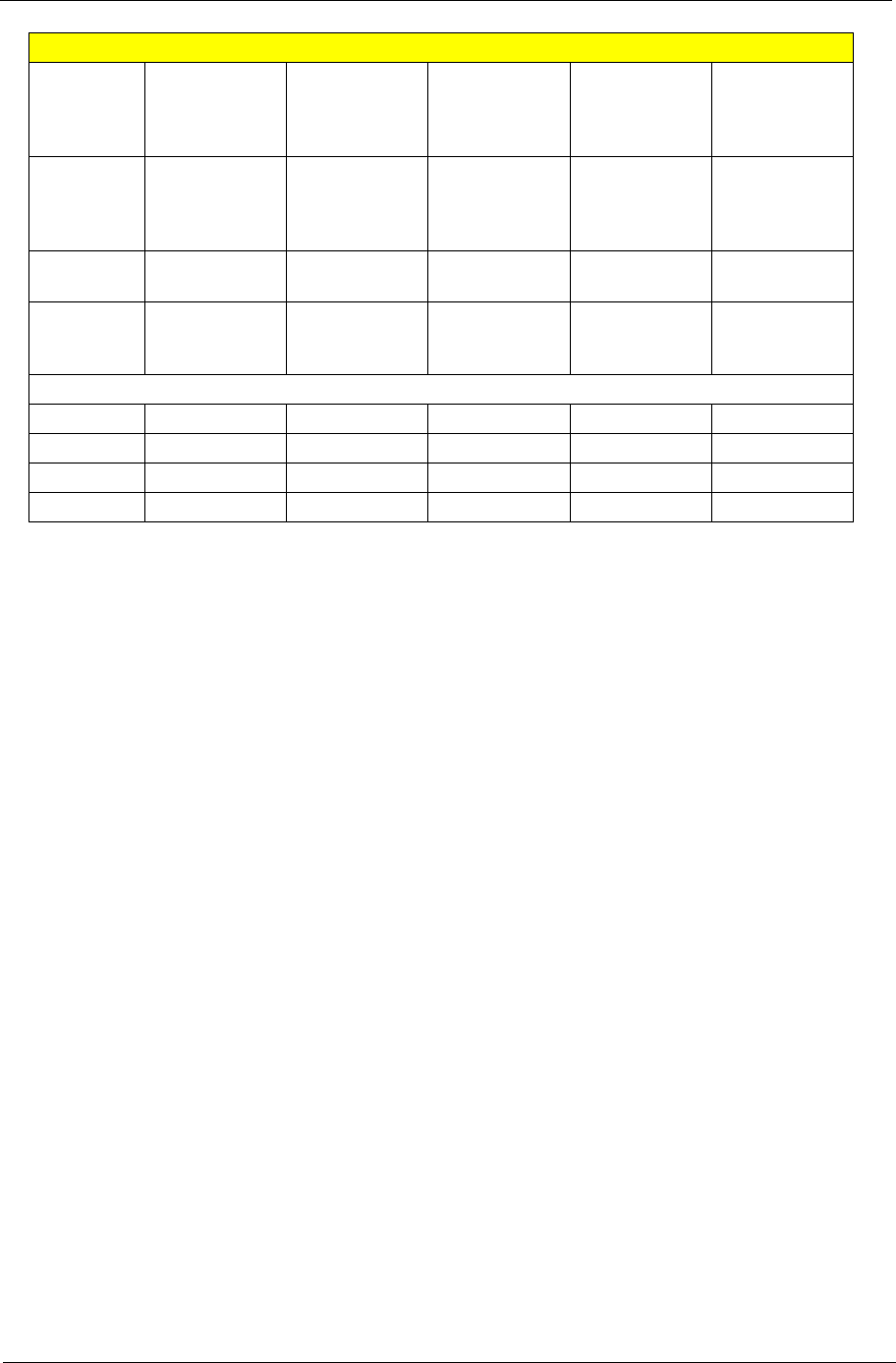
HGST
°°°
42 Chapter 1
Seagate
Specification
Model Name N2-50 ST960821A
60GB, 4200rpm
N2-50 ST9808210A
80GB, 4200rpm
Interface (Mbytes/sec.) Ultra ATA/100 Ultra ATA/100
Performance
Transfer Rate
Max Internal
(Mbytes/sec.)
48.25 48.25
Transfer Rate
Max External
(Mbytes/sec.)
100 100
Cache, Multisegmented
(Mbytes)
88
Average Seek (msec) 12.5 12.5
Average Latency (msec) 5.6 5.6
Performance Level24200 4200
Configuration/Orginzation
Discs/Heads 2/3 2/3
Bytes per Sector 512 512
Logical CHS 16383/16/63 16383/16/63
Recording Method RLL 0,11 RLL 0,11
Reliability/Data Integrity
Head-Rest Method Quick Step Ramp Load Quick Step Ramp Load
Nonrecoverable Read
Error per Bits Read
1 per 1014 bits read
Poewr Management
Temperature, Operating (oC) 5oC to 55oC5
oC to 55oC
Temperature, Nonoperating (oC) -40oC to 70oC-40
oC to 70oC
Shock, Operating : 2 msec(Gs) 250 250
Shock, Nonoperating : 1 msec
(Gs)
900 900
Acoustics
Idle (bels-sound power)
2.4 2.4
Quick Seek
(bels-sound power)
2.6 2.6
Performance
(bels-sound power)
2.9 2.9
Physical
Height (in/mm) .374/9.5 .374/9.5
Width (in/mm) 2.75/69.85 2.75/69.85
Depth (in/mm) 3.945/100.2 3.945/100.2
Weight (lb/g) .22/98 .22/98

Chapter 1 43
Storage
Item Specifications Details
Capacity 40/60/80 GB ATA/100 hard disc drive
TOne 40GB and above E-IDE hard disc
TOne 60GB and above E-IDE hard disc
TOne 5.25-inch internal remobable optical drive
Optical Drive Options DVD-Dual drive
DVD/CD-RW combo drive
Disc Performance
Compatibility
DVD-Dual Drive (Read) T24X CD-ROM
T8X DVD+R
T8X DVD-R
T8X DVD-ROM
T4X DVD-RW
T4X DVD+RW
DVD-Dual Drive (Write) T24X CD-RW
T24X CD-R
T8X DVD+R
T8X DVD-R
T4X DVD+RW
T4X DVD-RW
DVD/CD-RW Combo Drive (Read) T24X CD-RW
T24X CD-ROM
T24X CD-R
T8X DVD+R
T8X DVD-R
T8X DVD-ROM
T4X DVD+RW
T4X DVD-RW
DVD/CD-RW Combo Drive (Write) T24X CD-RW
T10X CD-R
Card Reader
( for TM 4600 and AS 1690 )
TSecure Digital (SD)
TMultiMedia Card (MMC)
TMemory Stick
TMemory Stick ProTM
44 Chapter 1
DVD ROM
Item Specification
Model Name QSI, SDR-083
Diameter 12cm and 8cm
Capacity 4.7 GB(mode 1, 12cm disk)
Transfer rate 11.08 MB/s max(read)
Access Time DVDROM 120 (typical)
Voltage DC +/- 5V +/-5%
Current 1.5 A (max)
Dimension 128.0x12.7x129.0
Weight Aluminum 195 g
Metal 235 g
MTBF 120000 POH (10 % duty)
Temperature Operation 5oC
Non-Operation -20oC
DVD/CD RW Combo
Item Specification
Model Name QSI, SBW-242
Diameter 12cm and 8cm
Capacity CDROM 650 MB(mode 1, 12cm disk)
DVDROM 4.7 GB(mode 1, 12cm disk)
Transfer rate CDROM 3.6 MB/s max(read)
DVDROM 11.08 MB/s max(read)
WriteSpeed 3.6 MB/s (typical)
Access Time CDROM 150 (typical)
DVDROM 150 (typical)
Voltage DC +/- 5V +/-5%
Current 1.5 A (max)
Dimension 128.0x12.7x129.0
Weight Aluminum 190 g
Metal 235 g
MTBF 60,000 POH (20 % duty)
Temperature Operation 5oC
Non-Operation -20oC
Chapter 2 45
BIOS Setup Utility
The BIOS Setup Utility is a hardware configuration program built into your computer’s BIOS (Basic Input/
Output System).
Your computer is already properly configured and optimized, and you do not need to run this utility. However,
if you encounter configuration problems, you may need to run Setup. Please also refer to Chapter 4
Troubleshooting when problem arises.
To activate the BIOS Utility, press m during POST (when “Press <F2> to enter Setup” message is prompted
on the bottom of screen).
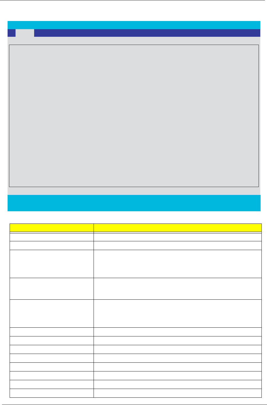
The setup screen displays BIOS as follows:Navigating the BIOS Utility
During setup,all Fn function keys and power saving functions are disabled.
There are five menu options: Main, Advanced, Security, Boot and Exit.
Follow these instructions:
TTo choose a menu, use the cursor left/right keys (zx).
TTo choose a parameter, use the cursor up/down keys ( wy).
TTo change the value of a parameter, press p or q.
TPress ^ while you are in any of the menu options to go to the Exit menu.
TIn any menu, you can load default settings by pressing t. You can also press u to save any
changes made and exit the BIOS Setup Utility.
NOTE: You can change the value of a parameter if it is enclosed in square brackets. Navigation keys for a
particular menu are shown on the bottom of the screen. Help for parameters are found in the Item
Specific Help part of the screen. Read this carefully when making changes to parameter values.
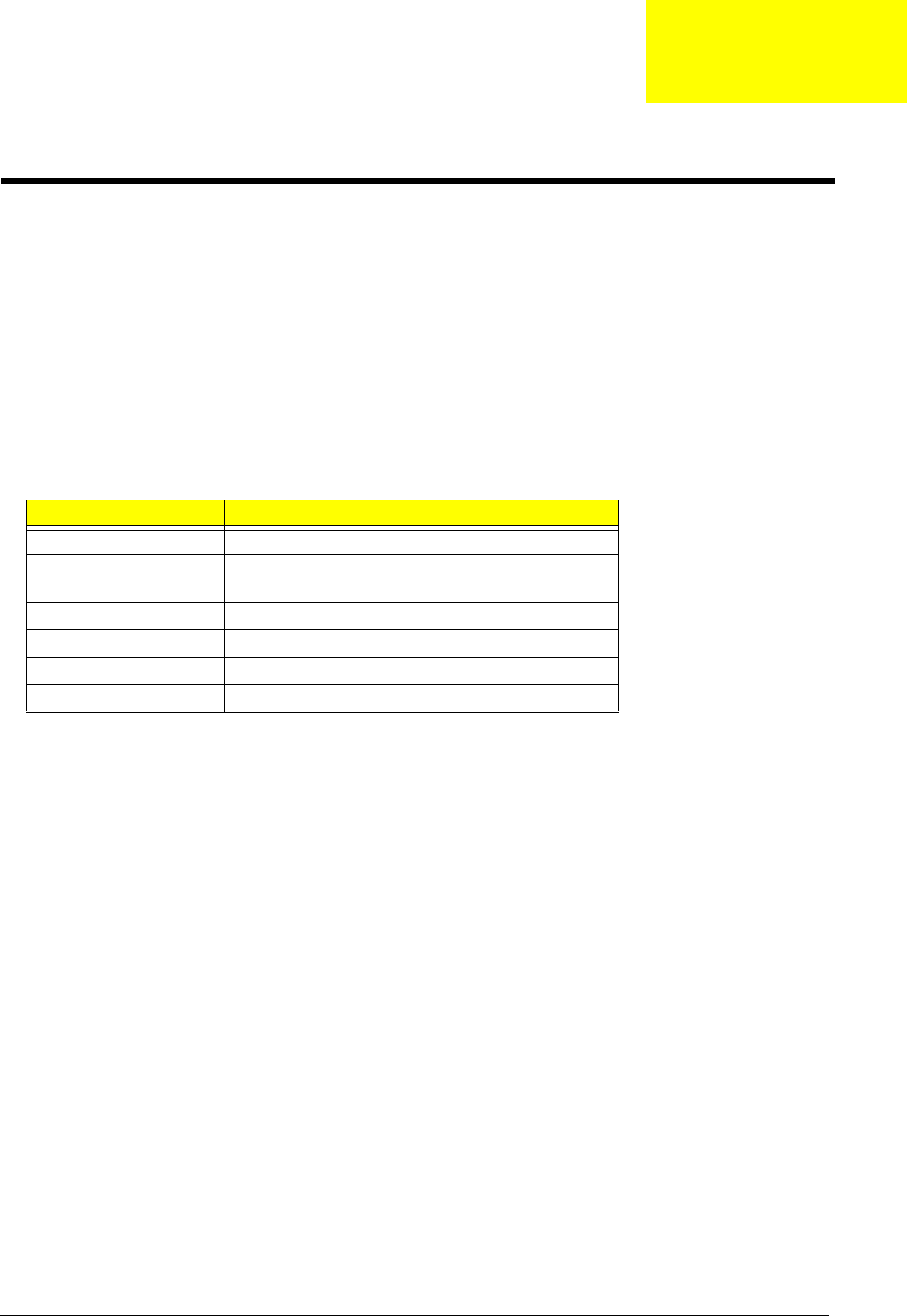
Function Item
Information Display the system informations
Main Allows the user to specify standard IBM PC AT
system parameters
Advanced Provides advanced settings of the system
Security Provides security settings of the system
Boot Allows the user to specify the boot options
Exit Allows the user to save CMOS setting and exit Setup
System Utilities
Chapter 2
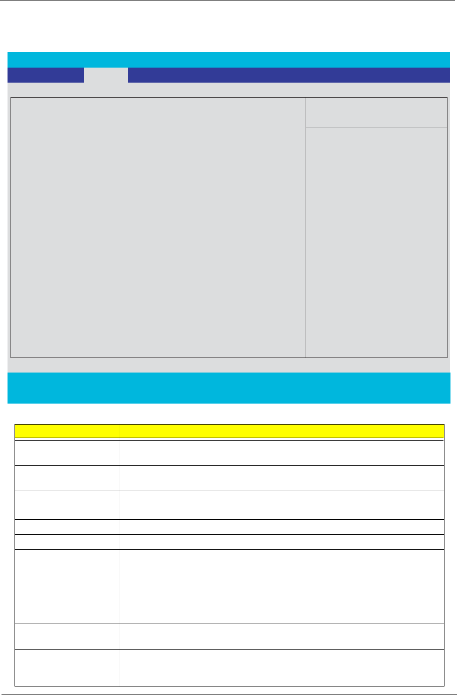
46 Chapter 2
Information
Parameter Description
CPU Type
CPU Speed
HDD Model Name This item will show the Model name of HDD installed on Primary IDE
master. The hard disk model name is automatically detected by the
system. If there is no hard disk present or unknown type, “None”
should be shown on this field
HDD Serial Number This item will show the Serial number of HDD installed on Primary IDE
master. If no Hard disk or other devices are installed on Primary IDE
master, then it will display a blank line
ATAPI Model Name This item will show the model name of DVD/CD-ROM drive installed on
system. The DVD/CD-ROM model name is automatically detected by
the system. If there is no DVD/CD-ROM model present or unknown
type, “None” should be shown on this field
System BIOS Version This field reports the BIOS version of system
VGA BIOS Version This field reports the VGA version of the system
KBC Version
Serial Number This item will show the Serial number of system.
Asset Tag Number This item will show the Asset Tag number of the system.
Product Name This field will show product name.
Manufacturer Name This field will show manufacturer name.
UUID This will be visible only when there is an internal LAN device present.
PhoenixBIOS Setup Utility
. Info. Main Advanced Security Boot Exit
CPU Type:: Intel (R) Pentium (R) M processor 1.73GHz
CPU Speed:
System BIOS Ver:
S3A11
VGA BIOS Ver:
ATi 008.018M.039.000
KBC Ver:
1A20
Serial Number xxxxxxxxxxxxxxxxxxxxxx
Asset Tag Number:
N/A
Product
TravelMate 4600
Manufacturer Name:
Acer
UUID:
xxxxxxxxxxxxxxxxxxxxxxxxxxxxxxxx
F1 Help
↑↓
Select Item F5/F6 Change Values F9 Setup Defaults
Esc Exit
←
→
Select Menu Enter Select
4
Sub-Menu F10 Save and Exit
HDD Model Name:
HDD Serial Number:
TOSHIBA MK4025GAS
Y4C59830S
1733 MHz
ATAPI Device: HL-DT-ST DVDRAM GMA-4080N
Chapter 2 47
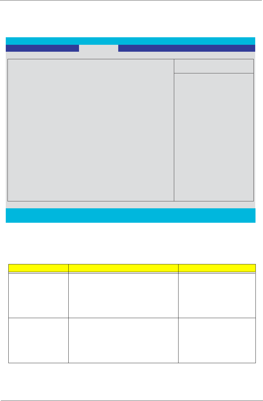
Main
This menu provides you the information of the system.
Parameter Description
System Time / System
Date
The hours are displayed with 24 hours format. The values set in these two fields
take effect immediately.
System Memory This field reports the memory size of system base memory. The size is fixed to
640KB.
Extended Memory This field reports the memory size of the extended memory in the system.
Extended Memory size = Total memory size - 1 MB
Video Memory VGA Memory size = 128MB
Quiet Boot Customer Logo display will be shown during POST when it is selected.
Power on display Auto: During power on process, the system will detect if any display
device is connected on external video port. If any external display device is
connected, the power on display will be in CRT (or projector) only mode.
Otherwise it will be in LCD only mode.
Both: Simultaneously enable both the integrated LCD screen and the system’s
external video port (for an external CRT or projector).
Network boot When this is selected, Boot from LAN feature is enabled. When this is not
selected, Boot from LAN feature is then disabled.
F12 Boot Menu When this is selected, users can modify device boot priority by pressing F12 key
during POST. When this is not selected, device boot priority will not be
adjustable during POST.
PhoenixBIOS Setup Utility
Info.
Main Advanced Security Boot Exit
Item Specific Help
System Time: [02:19:31]
System Date: [04/21/2004]
System Memory: 624 KB
Extended Memory: 522240 KB
Video Memory 128 MB
Quiet Boot: [Enabled]
Power on Display: [Auto ]
Network Boot: [Enabled]
F12 Boot Menu:
D2D Recovery : [Enabled]
Processor Power Management: [Enabled]
[Disabled]
<Tab>, <Shift-Tab>, or
<Enter> selects field.
F1 Help
↑↓
Select Item F5/F6 Change Values F9 Setup Defaults
Esc Exit
←
→
Select Menu Enter Select
4
Sub-Menu F10 Save and Exit
Shows system base memory size
Shows extended memory size
VGA memory size

48 Chapter 2
D2D Recovery Allow user to enable/disable the Disk-to-Disk recovery
Processor Power
Management
Selects the Processor Power Management desired:
Disabled= C states and GV1/GV3 are disabled
GV1/GV3 only= C states are disabled
C States Only= GV1/GV3 are disabled
Enabled= C States and GV1/GV3 are enabled
Parameter Description
Chapter 2 49
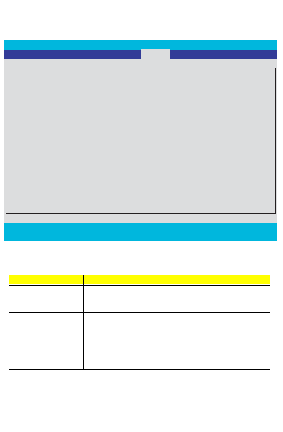
Advanced
The Advanced screen contains parameters involving your hardware devices. It also provides advanced
settings of the system.
The table below describes the parameters in the screen. Settings in boldface are the default and suggested
parameter settings.
Description Option
Serial port A Configure serial port A using options:
[Disabled]: No configuration
[Enabled]: User configuration
[Auto]: BIOS or OS chooses configuration
(OS Controlled) Displayed when controlled
by OS
Disabled
Enabled
Auto
Infrared Port Configure serial port B using options:
[Disabled]: No configuration
[Enabled]: User configuration
[Auto]: BIOS or OS chooses configuration
(OS Controlled) Displayedd when controlled
by OS
Disabled
Enabled
Auto
PhoenixBIOS Setup Utility
Info. Main Advanced Security Boot Exit
Item Specific Help
Serial Port A
Configure serial port A
using options:
[Disable]
No configuration
[Enabled]
User configuration
[Auto]
BIOS or OS chooses
configuration
(OS Controlled)
Displayed when controlled
by OS
F1 Help
↑↓
Select Item F5/F6 Change Values F9 Setup Defaults
Esc Exit
←
→
Select Menu Enter Select
4
Sub-Menu F10 Save and Exit
Parallel port:
Mode:
[Auto]
[Auto]
[Auto]
[ECP]
Internal Touchpad: [Both]
Infrared Port :

50 Chapter 2
Parallel port Configure serial port B using options:
[Disabled]: No configuration
[Enabled]: User configuration
[Auto]: BIOS or OS chooses configuration
(OS Controlled) Displayedd when controlled
by OS
Disabled
Enabled
Auto
Mode Set the mode for the parallel port using
options:
Output only Bi-directional
EPP
ECP
Output only
Bi-directional
EPP
ECP
Internal TouchPad Configure touch pad
[Both]: Enable both touch pad and PS/2
mouse
[Auto]: If PS/2 mouse exist, disable touch
pad
Both
Auto
Description Option
Chapter 2 51
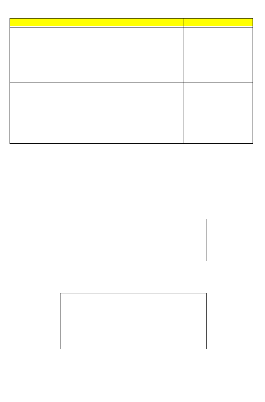
Security
The Security screen contains parameters that help safeguard and protect your computer from
unauthorized use.
The table below describes the parameters in this screen. Settings in boldface are the default and
suggested parameter settings.
Parameter Description Option
Supervisor Password Is N/A N/A
User Password Is N/A N/A
HDD Password Is N/A N/A
HDD Master ID N/A N/A
Set Supervisor Password Press Enter to set the administrator
password. When set, this password
protects the BIOS Setup Utility from
unauthorized access.
[Set]: System password is set
[Clear]: System password is not set
Length -- No more than 8
characters
Characters -- 0-9, A-Z (not
case sensitive)
Set User Password
PhoenixBIOS Setup Utility
Info. Main Advanced Boot
Item Specific Help
Supervisor Password Is: Clear
User Password Is: Clear
HDD Password Is:
[Enter]
Set Supervisor Password
Password on boot
[Disabled]
Supervisor Password
controls accesses to the
setup utility.
F1 Help
↑↓
Select Item F5/F6 Change Values F9 Setup Defaults
Esc Exit
←
→
Select Menu Enter Select
4
Sub-Menu F10 Save and Exit
Set User Passord [Enter]
Clear
HDD Master ID: 43883467
Set HDD Password [Enter]
Exit
Security
52 Chapter 2
Set Supervisor/User Password
If password on boot is required, the password must be set otherwise it cannot be enabled.
The formats of the password are as follows:
Length No more than 8 characters
Characters 0-9,A-Z (not case sensitive)
While these fields are highlighted and press “Enter”, a window similar to the following is shown:
If there is an old password then setup will prompt with the following window instead and a current password
will be required to be entered at first:
Set HDD Password When shown as [Locked], the hard drive
password currently can not be changed
or disabled.
To change or disable it, turn off the
system and enter Setup immediately after
turning it back on.
Press [Enter] to input change, or disable
hard drive password.
Enter
Password on boot Defines whether a password is required
or not while the events defined in this
group happened. The following sub-
options are all requires the Supervisor
password for changes and should be
grayed out if the user password was used
to enter setup.
Allows the user to specify whether or not
a password is required to boot.
Disabled
Enabled
Parameter Description Option
Set SupervisorPassword
Enter New Password [ ]
Confirm New Password [ ]
Set Supervisor Password
Enter current password [ ]
Enter New Password [ ]
Confirm New Password [ ]

Chapter 2 53
User can now type password in field “Enter New Password”, and re-enter password in field “Confirm New
Password” for verification.
If the verification is OK:
The password setting is complete after user presses enter.
If the current password entered does not match the actual current password:
If the new password and confirm new password strings do not match:
Setup Notice
Changes have been saved.
[ continue]
Setup Warning
Invalid password
Re-enter Password
[ continue]
Setup Warning
Password do not match
Re-enter Password
54 Chapter 2
Boot
This menu allows the user to decide the order of boot devices to load the operating system. Bootable
devices includes the distette drive in module bay, the onboard hard disk drive and the CD-ROM
in module bay and onboard LAN device.
.
Parameter Description
+Hard Drive + and - indicate device categories. Use <Enter> to expand/
collapse.
Boot order is top-down using only the top device in each
category.
Use <F6> and <F5> to move highlighted item up and down.
Floppy Devices
CD-ROM/DVD Drive
Netword Boot
PhoenixBIOS Setup Utility
Info. Main Advanced Security Exit
Item Specific Help
CD-ROM/DVD Drive
+Hard Drive
+ and - indicate device
categories. Use <Enter> to
expand/collapses.
Boot order is top-down using
only the top device in each
category.
Use <F6> and <F5> to move
highlighted item up and down.
F1 Help
↑↓
Select Item F5/F6 Change Values F9 Setup Defaults
Esc Exit
←
→
Select Menu Enter Select
4
Sub-Menu F10 Save and Exit
Network Boot
Boot
Floppy Devices
Chapter 2 55
Exit
The Exit screen contains parameters that help safeguard and protect your computer from unauthorized use.
The table below describes the parameters in this screen.
Parameter Description
Exit Saving Changes Exit System Setup and save your changes to CMOS
Exit Discarding
Changes
Exit utility without saving Setup data to CMOS
Load Setup Default Load default values for all SETUP items
Discard Changes Load previous values from CMOS for all SETUP items
Save Changes Save Setup Data to CMOS
PhoenixBIOS Setup Utility
Info. Main Advanced Security Boot
Item Specific Help
Exit Saving Changes
Exit Dicarding Changes
Load Setup Defaults
Exit System Setup and save
your changes to CMOS.
F1 Help
↑↓
Select Item F5/F6 Change Values F9 Setup Defaults
Esc Exit
←
→
Select Menu Enter Select
4
Sub-Menu F10 Save and Exit
Discard Changes
Exit
Save Changes

Chapter 3 56
This chapter contains step-by-step procedures on how to disassemble the notebook computer for
maintenance and troubleshooting.
To disassemble the computer, you need the following tools:
TWrist grounding strap and conductive mat for preventing electrostatic discharge
TSmall Philips screw driver
TPhilips screwdriver
TPlastic flat head screw driver
TTweezers
NOTE: The screws for the different components vary in size. During the disassembly process, group the
screws with the corresponding components to avoid mismatch when putting back the components.
When you remove the stripe cover, please be careful not to scrape the cover.
Chapter 3
Machine Disassembly and Replacement
57 Chapter 3
General Information
Before You Begin
Before proceeding with the disassembly procedure, make sure that you do the following:
1. Turn off the power to the system and all peripherals.
2. Unplug the AC adapter and all power and signal cables from the system.
3. Remove the battery pack.
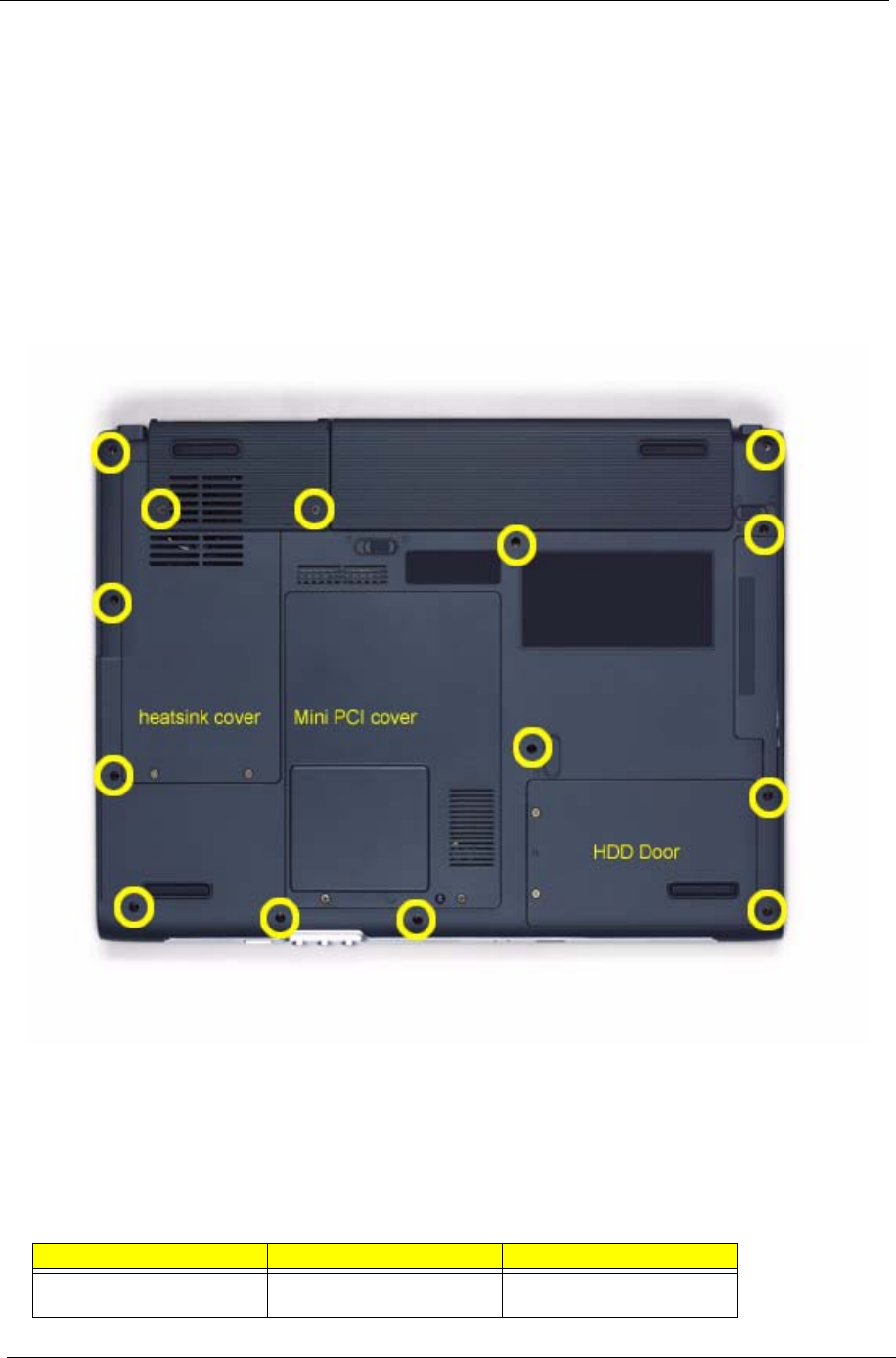
NOTE: The screws used to secure bottom case and upper case are more than one type. Please group same
type of screw together as you disassemble the system for service purpose. The image below is for your
reference. Please pay attention to the explanation below.
The screws that secure heatsink cover, MIni PCI cover and HDD cover are with the covers. There is no need
to worry about mix them up. However, please notice that you have to group the screws on the following
locations together. There are twenty screws holding the bottom case to upper case but some screws are inside
the system. You may have to remove the HDD, the heatsink cover to see these screws. Mini PCI cover here
also called RAM/Wireless cover.
Screw Type Location Quantity
M2.5*6 Bottom case and IO bezel
(hightlight with yellow circle)
14
IO Bezel Battery

Chapter 3 58
M2.5*6 Remove the IO bezel then
you will see.
2
M2.5*6 Remove the heatsink cover
then you will see.
1
M2.5*6 Remove the HDD cover then
you will see.
1
M2.5*3 Detach the HDD module
then you will see.
1
M2.5*3 Remove the battery then you
will see.
1
Screw Type Location Quantity
59 Chapter 3
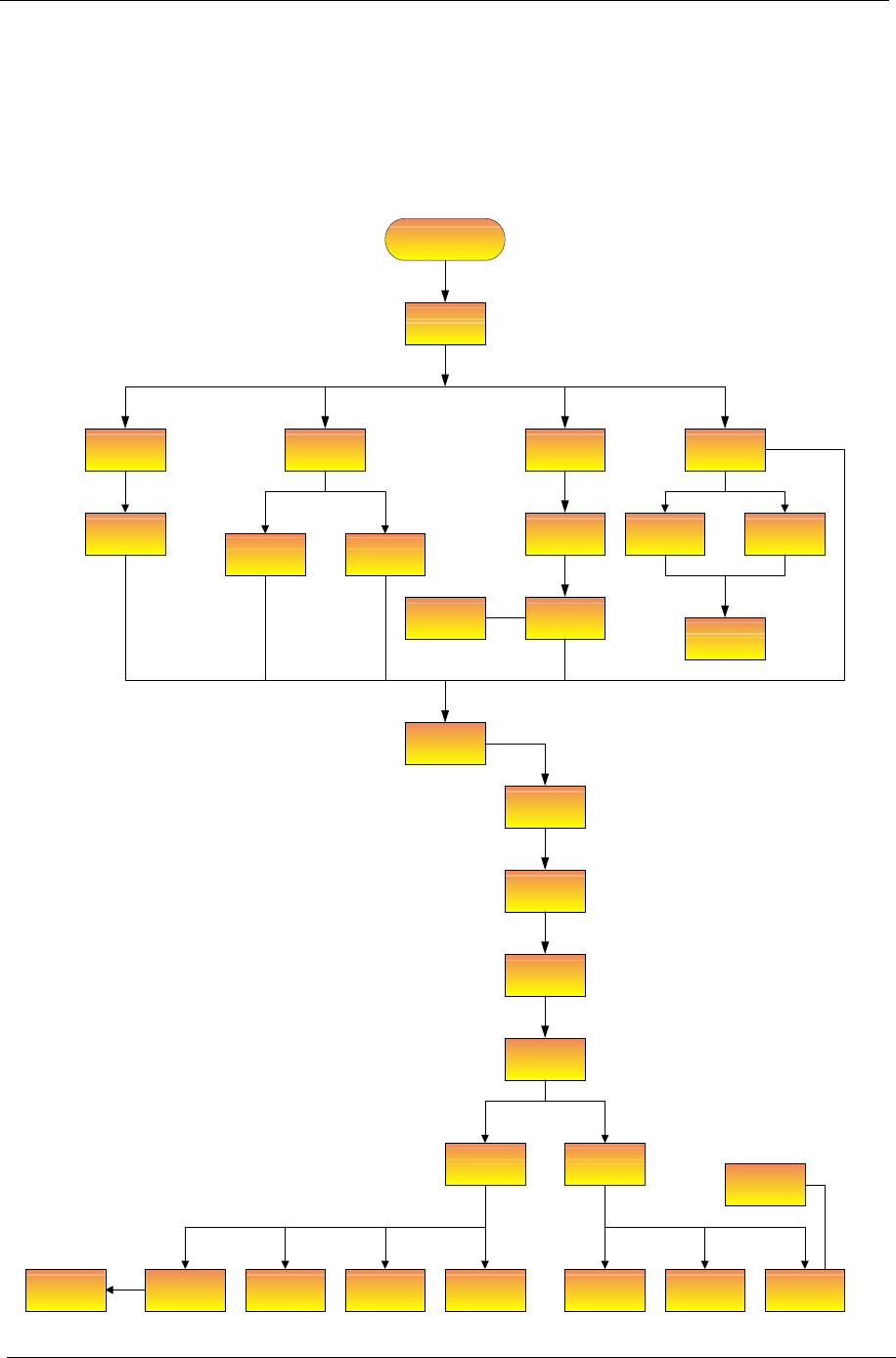
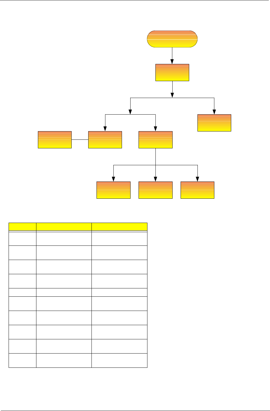
Disassembly Procedure Flowchart
The flowchart on the succeeding page gives you a graphic representation on the entire disassembly sequence
and instructs you on the components that need to be removed during servicing. For example, if you want to
remove the system board, you must first remove the keyboard, then disassemble the inside assembly frame in
that order.
Start
Battery
HDD Cover ODD Module
RAM/Wireless
Cover
E*2
K*2
HDD Module
Wireless LAN
Card Memory
IO Bezel
*2
*2
Heatsink
Cover
*2
Thermal
Module
CPU
ODD
Connector
Board
ODD Holder
ODD Drive
*6
*3
Middle Cover
*2
Keyboard
*4
(right and left hinges)
LCD Module
*2
Switch Board
*5
*18
Lower and
Upper Case
Assembly
Upper Case
Assembly
Lower Case
Assembly
3-in-1 Cover Speaker Set Modem Board
Touchpad
Bluetooth
Module
Touchpad
Board
Touchpad
Bracket
*2
Main Board
*4
*2
*2 screw nuts
VGA Heatsink *3
Chapter 3 60
Screw List
Item Description
SCREW M2.0X3.0-I-NI-
NYLOK
86.A03V7.012
SCREW I2.5*3M-
BNIH(M2.5L3)
86.T25V7.012
SCREW M2.5*4L-BZN-
NYLOK
86.A03V7.006
SCREW M2.0X5-I-NI-
NYLOK
86.T23V7.006
SCREW MM25060IL69 86.A08V7.004
SCREW M2.0*5-
I(NI)(NYLOK)
86.T23V7.010
SCREW M2.0X2.5-I-NI-
NYLOK
86.A03V7.007
SCREW I2*3M-NIHY
(M2L3)
86.T25V7.008
SCREW M1.7*3.0-I
(BK)
86.T50V7.001
SCREW I3*3.5M-
NIH(M3L3.5)
86.A03V7.011
4 screw pads
M*4
LCD Bezel
*6 hinges
*2 brackets
LCD Inverter
LCD
Assembly
LCD Cover
*4
LCD Module
LCD LCD Cable LCD Brackets
Antenna set
61 Chapter 3
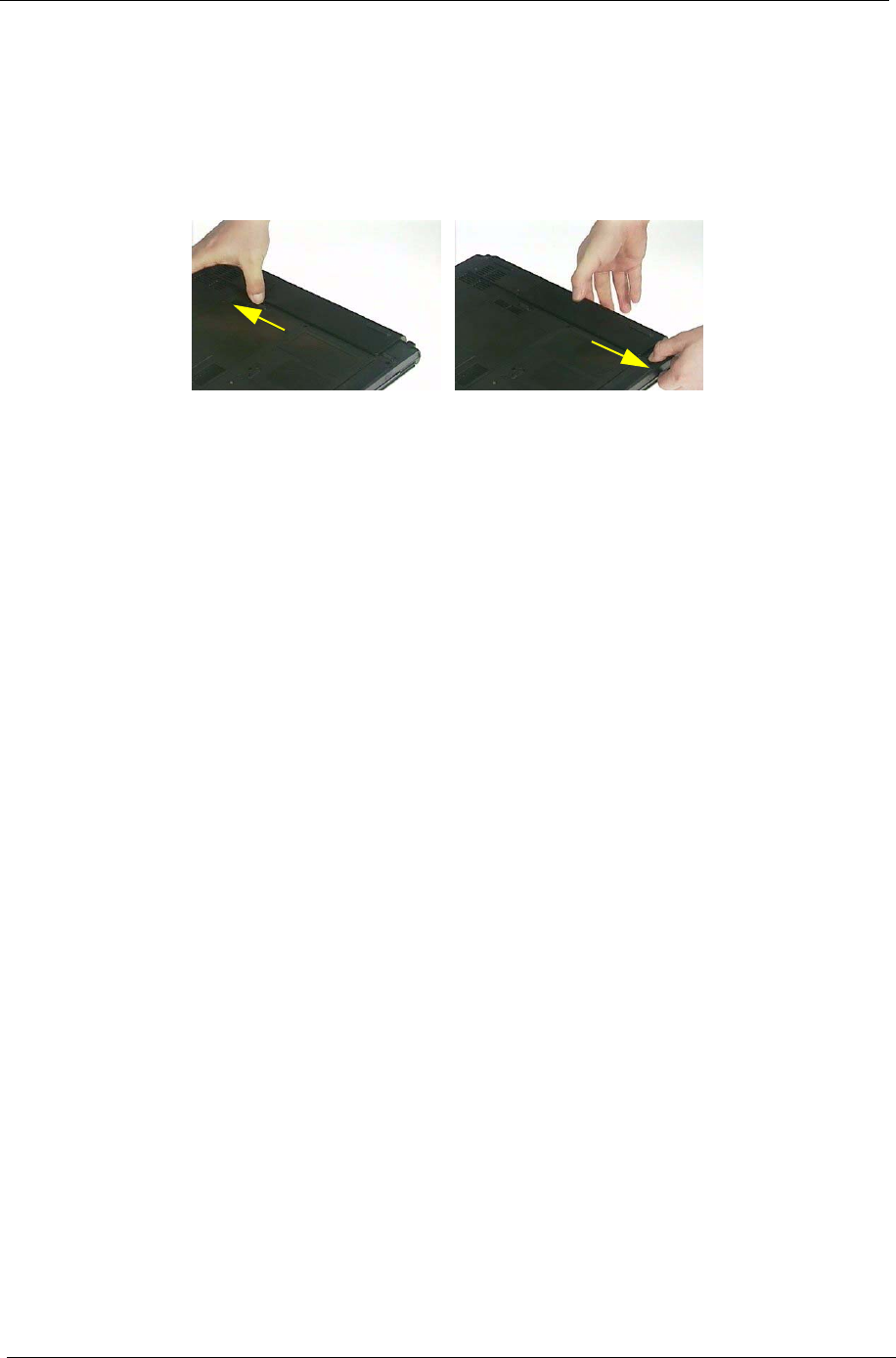
Removing the Battery Pack
NOTE: This chapter is base on Aspire 1410 and Aspire 1680 to edit. Since they have the similar disassemble
and reassemble procedures.
1. Unlock the battery lock.
2. Slide the battery latch as shown then remove the battery pack.
Chapter 3 62
Removing the HDD Module/the Memory and the Wireless LAN Card/the
Thermal Module and the CPU/ODD Module and LCD Module
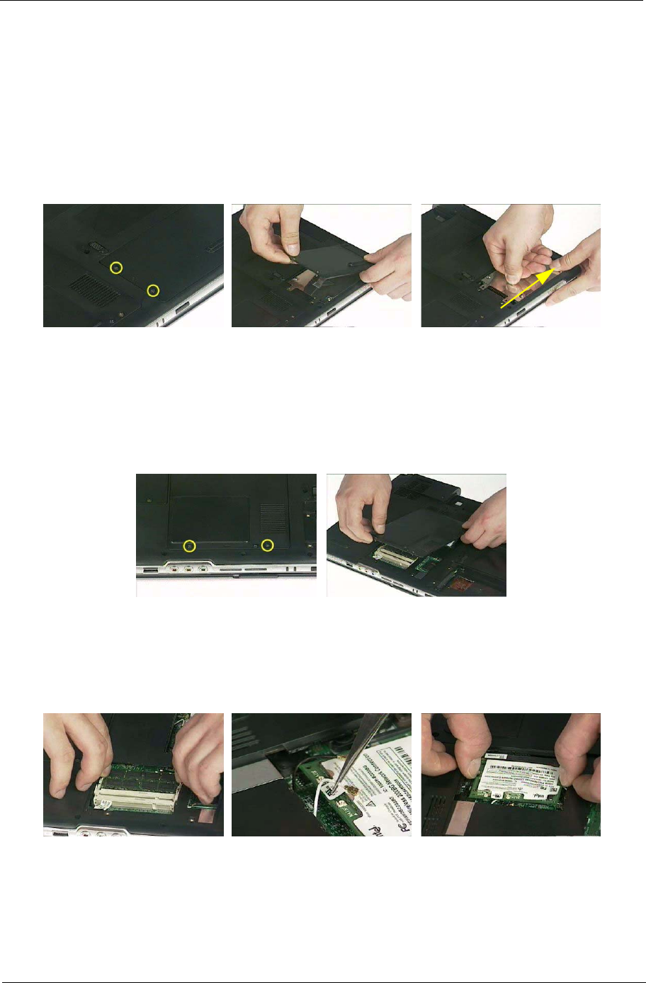
Removing the HDD Module
1. Remove the two screws holding the HDD cover.
2. Remove the HDD cover.
3. Detach the HDD module then remove it.
Removing the Memory and the Wireless LAN Card
1. Remove the two screws that secure the RAM/Wireless cover.
2. Remove the RAM/Wireless cover.
3. Pop up the memory then remove it.
4. Disconnect the auxiliary and the main wireless antennae.
5. Pop the wireless LAN card then remove it.
.
63 Chapter 3
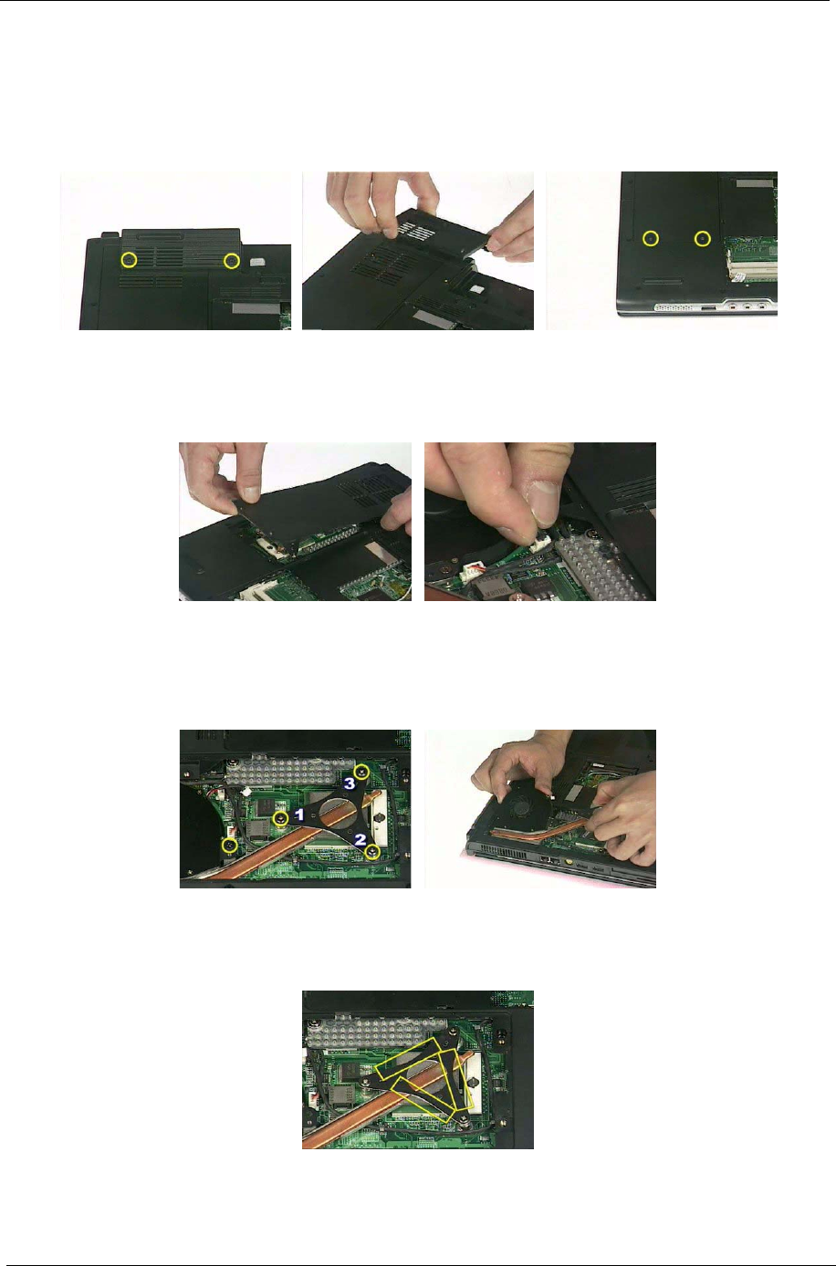
Removing the Thermal Module and CPU
1. Remove the two screws holding the IO bezel.
2. Then remove the IO bezel.
3. Remove the two screws that secure the heatsink cover.
4. Remove the heatsink cover from the main unit.
5. Disconnect the fan cable.
6. Remove the four screws that secure the thermal module.
7. Pull the thermal module outwards then remove it.
NOTE: The edge of the thermal module as shown is very sharp. Be very careful as you remove the thermal
module.
8. Use a flat-bladed screwdriver to release the CPU lock.
9. Remove the CPU from the socket carefully.
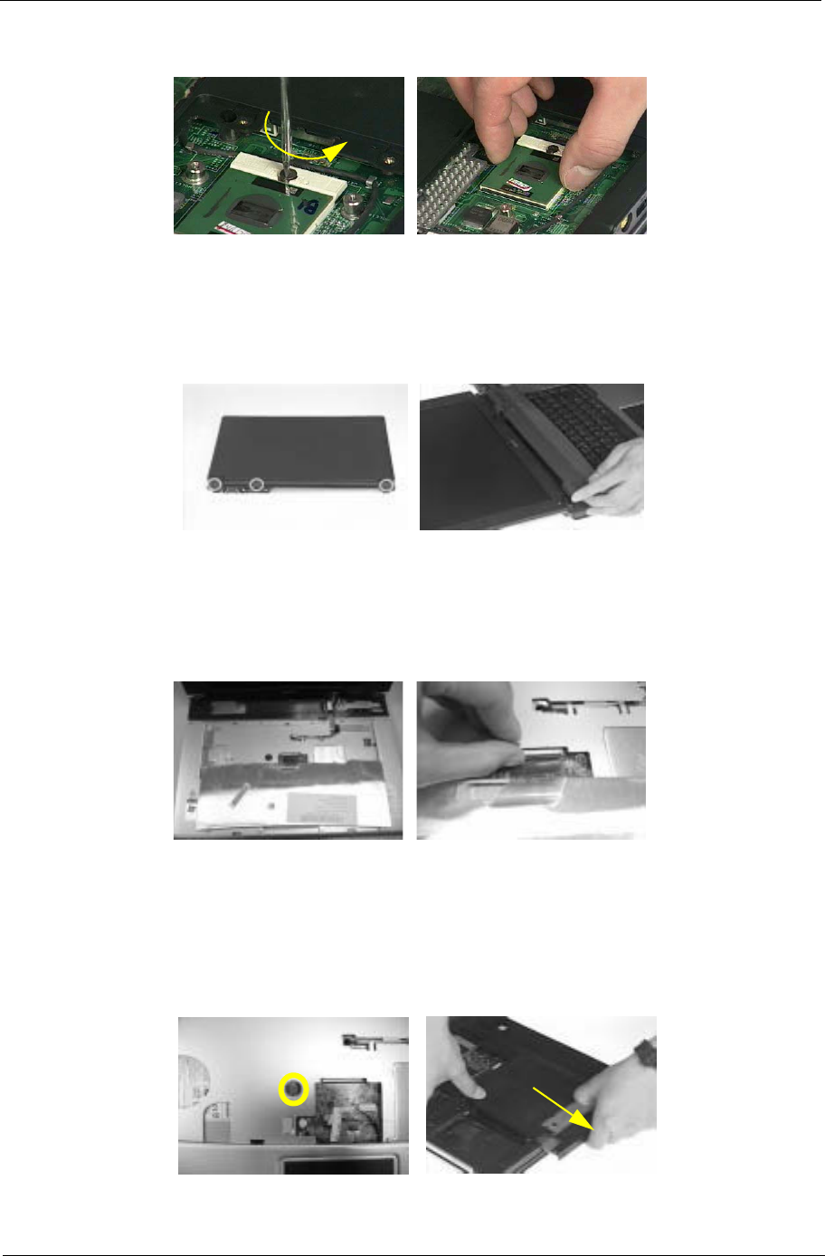
Chapter 3 64
Removing the ODD Module
1. Remove the three screws holding the middle cover.
2. Detach the middle cover carefully.
.
3. Turn over the keyboard as shown.
4. Disconnect the keyboard cable from the main board then remove the keyboard.
5. Remove the screw that fastens the ODD module.
6. Turn over the notebook computer then detach the ODD module carefully.
NOTE: When you reattach the ODD, please make sure you attach the ODD module completely to the main
unit. Otherwise, you can not fasten the screw and the screw may damage the main board.
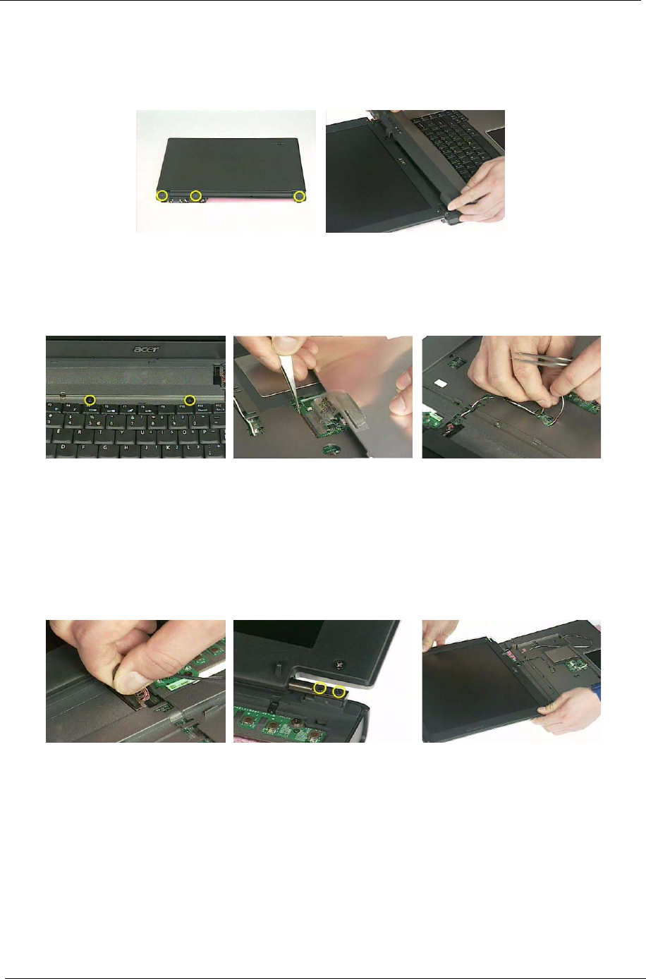
65 Chapter 3
Removing the LCD Module
1. Remove the three screws holding the keyboard cover.
2. Open the LCD module as the picture shown then detach the keyboard cover from the main unit.
.
3. Remove the two screws that secure the keyboard as shown.
4. Turn over the keyboard as shown and disconnect the keyboard cable then remove the keyboard.
5. Pull out the antenna set with a tweezers then take out the antenna set from the main unit.
.
6. Disconnect the LCD coaxial cable.
7. Remove the four screws holding the right and the left hinge. Two on each side.
8. Then detach the LCD module from the main unit.
.
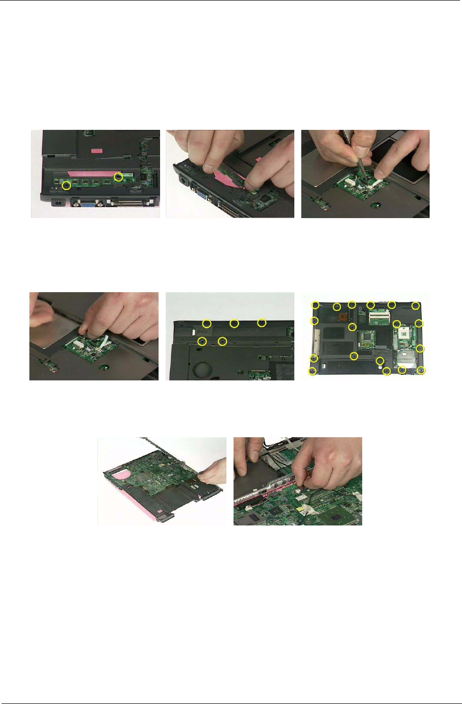
Chapter 3 66
Disassembling the Main Unit
Separate the Main Unit Into the Upper and the Lower Case Assembly
1. Remove the two screws holding the switch board.
2. Remove the switch board.
3. Disconnect the touchpad FFC from the main board.
4. Disconnect the bluetooth cable.
5. Remove the five screws that secure the upper case.
6. Remove the eighteen screws on the bottom as shown.
7. Detach the upper case assembly and place it next to the lower case assembly.
8. Disconnect the microphone cable then remove the upper case assembly.
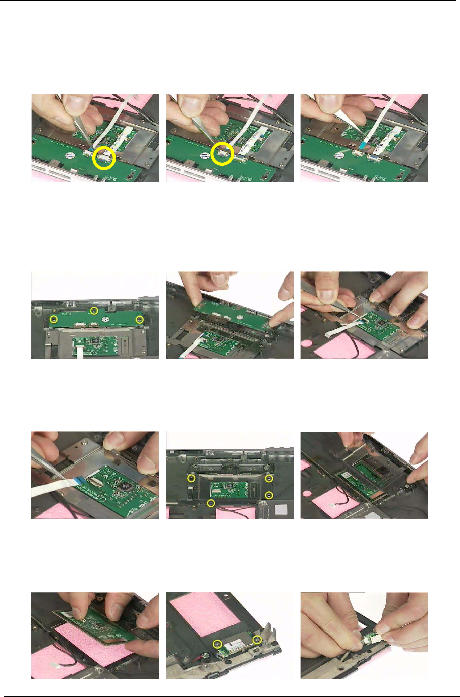
67 Chapter 3
Disassembling the Upper Case Assembly
1. Disconnect the touchpad board to touchpad FFC.
2. Disconnect the touchpad board to main board FFC.
3. Then detach the touchpad board to main board FFC from the touchpad board.
4. Remove the three screws that secure the touchpad board.
5. Remove the touchpad board from the upper case.
6. Disconnect the touchpad board to touchpad FFC.
7. Remove the touchpad board to touchpad FFC from the uppwer case assembly.
8. Remove the four screws holding the touchpad bracket.
9. Detach the touchpad bracket from the upper case assembly.
10. Remove the touchpad from the upper case.
11. Remove the two screws that secure the bluetooth module.
12. Disconnect the bluetooth module then remove it.
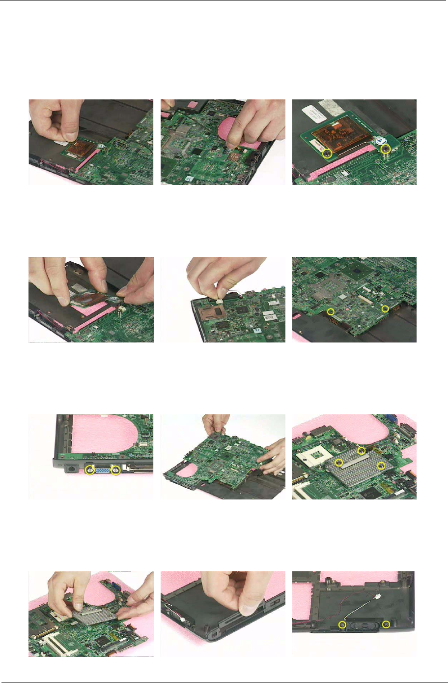
Chapter 3 68
Disassembling the Lower Case Assembly
1. Disconnect the MDC cable from the modem board.
2. Detach the MDC cable from the main board.
3. Remove the two screws holding the modem board.
4. Remove the modem board from the lower case.
5. Disconnect the speaker cable from the main board.
6. Remove the two screws that secure the main board.
7. Remove the two screw nuts as shown.
8. The you can detach the main board from the upper case.
9. Remove the three screws that secure the VGA heatsink.
10. Remove the VGA heatsink from the main board as shown.
11. Remove the three in one cover from the lower case.
12. Remove the two screws that secure the speaker set on one side.
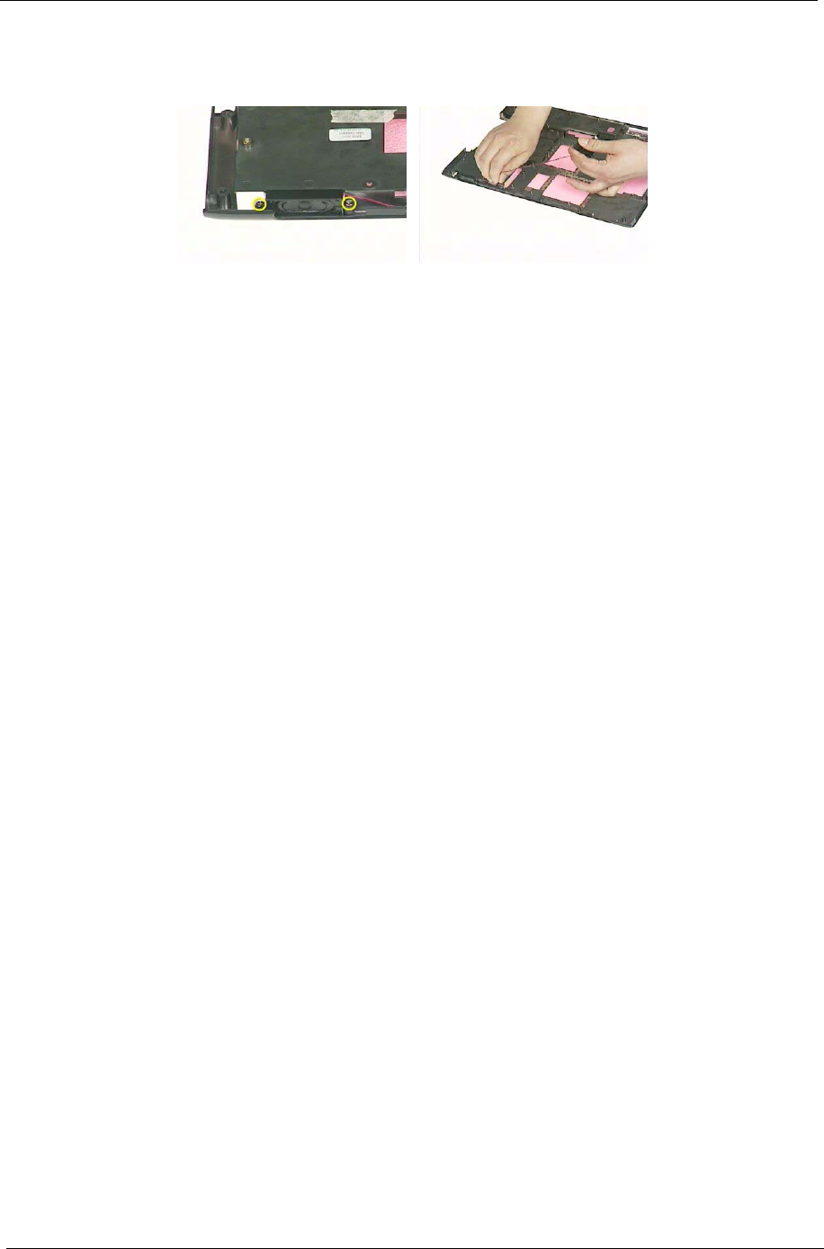
69 Chapter 3
13. Then remove another two screws holding the speaker set on the other side.
14. Then take out the speaker set from the lower case.
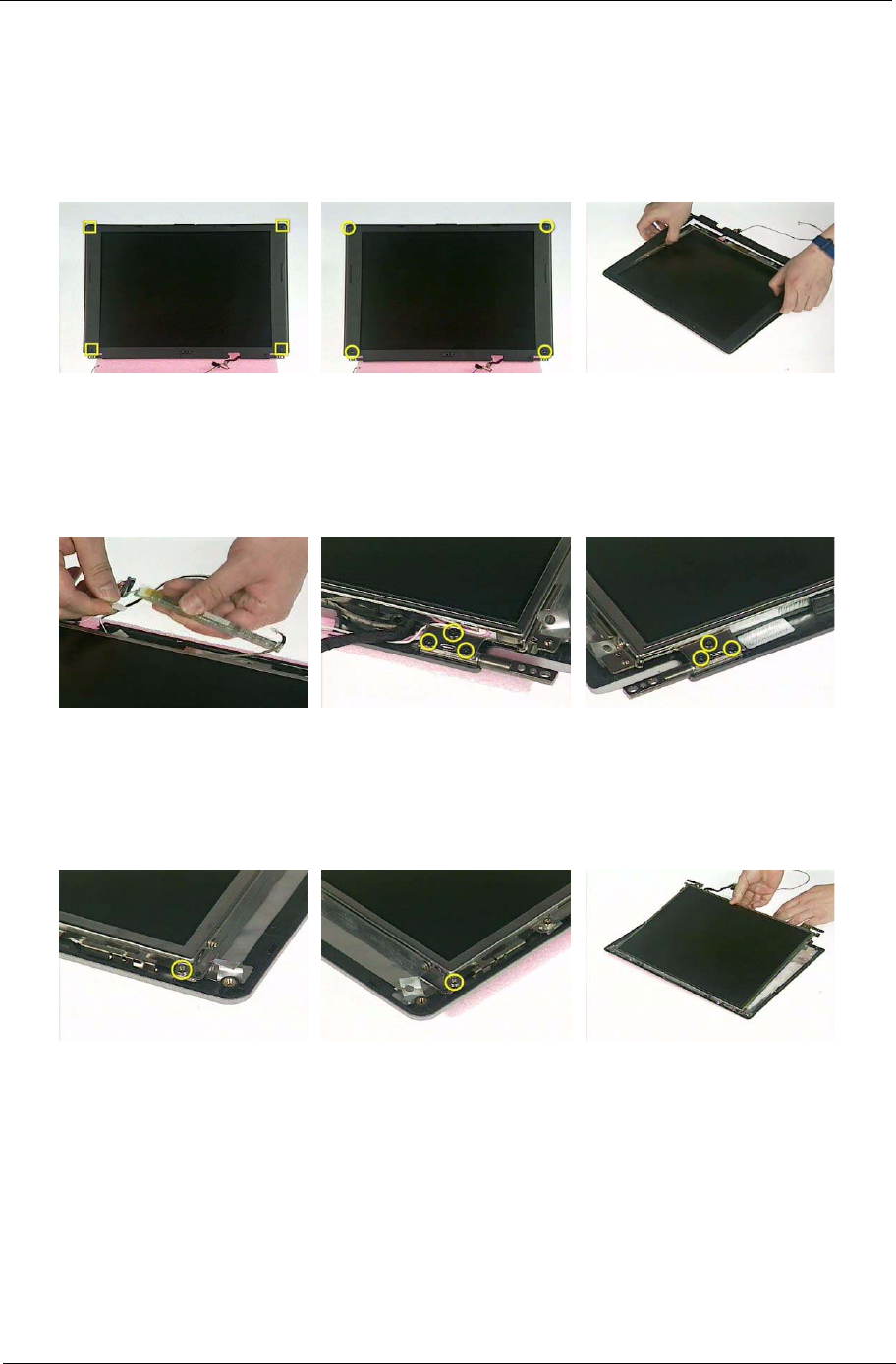
Chapter 3 70
Disassembling the LCD Module
1. Remove the four screw caps as shown.
2. Remove the four screws holding the LCD bezel.
3. Then detach the LCD bezel from the LCD module.
4. Disconnect the inverter board then remove it.
5. Remove the three screws holding the right hinge.
6. Then remove the three screws that secure the left hinge.
7. Remove one screw that secure the LCD bracket.
8. Remove another screw holding the LCD bracket on the other side.
9. Then detach the LCD panel from the LCD cover carefully.
.
10. Remove the two screws holding the right bracket.
11. Then remove the right bracket.
12. Remove another two screws that tighten the left bracket.
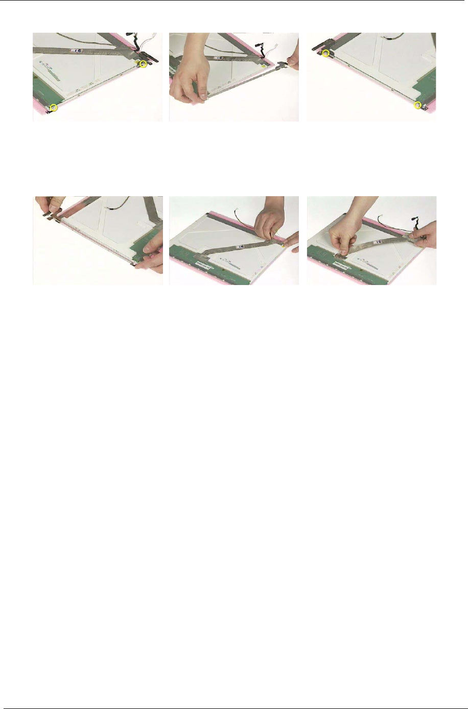
71 Chapter 3
13. Remove the left bracket as the picture shows.
14. Tear off the tape fastening the LCD cable.
15. Tear off the the LCD cable fastening the LCD cable, then remove it..
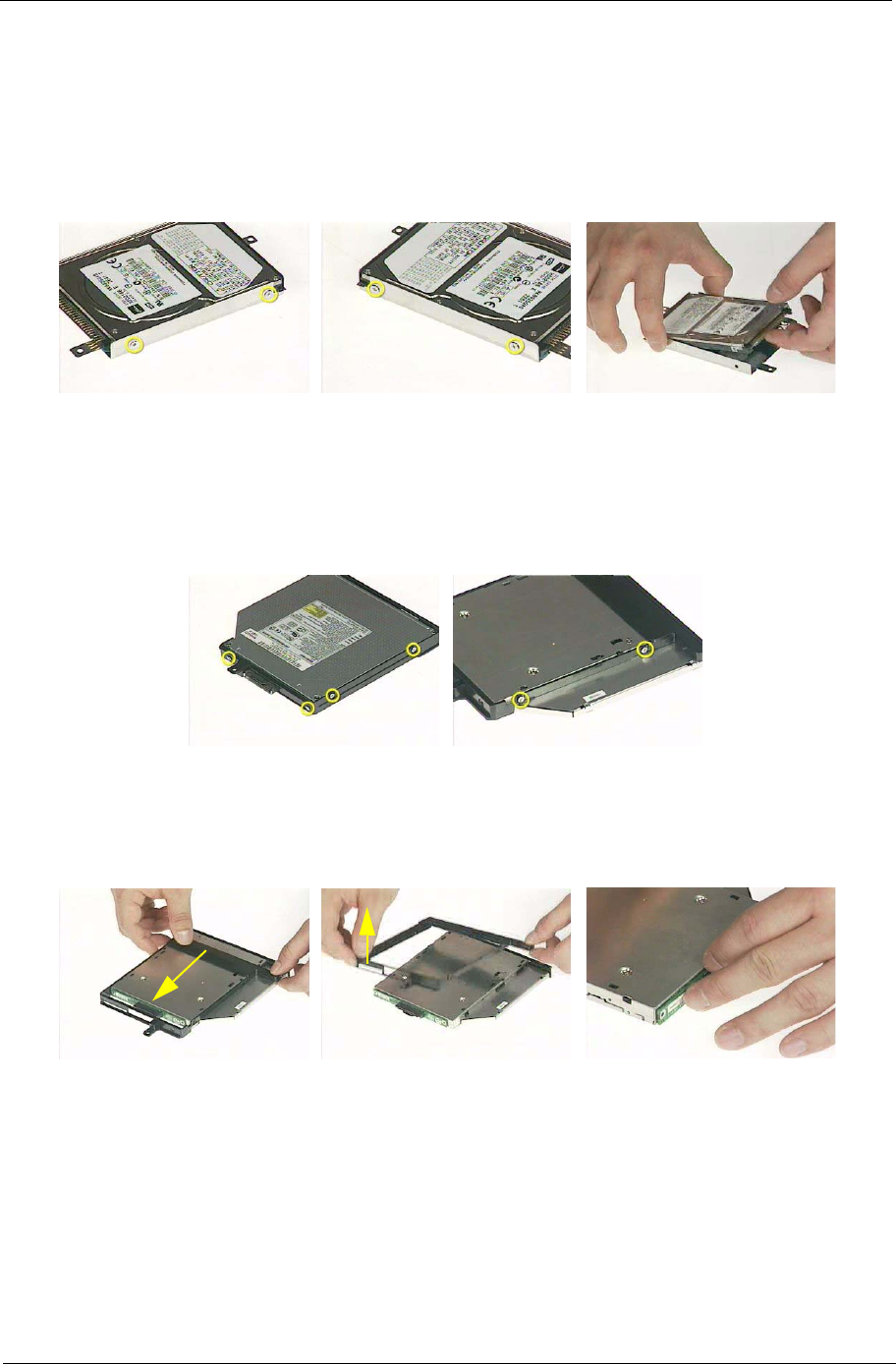
Chapter 3 72
Disassembling the External Modules
Disassembling the HDD Module
1. Remove the two screws holding the HDD bracket on one side.
2. Remove another two screws holding the HDD bracket on the other side.
3. Then take the hard disc drive out from the HDD bracket.
Disassembling the Optical Drive Module
1. Remove the four screws as the picture shows.
2. Remove the two screws that secure the optical disc drive and the ODD holder.
3. Push the ODD holder as shown.
4. Detach the ODD holder.
5. Disconnect the ODD connector board then remove it.

Chapter 4 73
Use the following procedure as a guide for computer problems.
NOTE: The diagnostic tests are intended to test only Acer products. Non-Acer products, prototype cards, or
modified options can give false errors and invalid system responses.
1. Obtain the failing symptoms in as much detail as possible.
2. Verify the symptoms by attempting to re-create the failure by running the diagnostic test or by repeating
the same operation.
Troubleshooting
Chapter 4

74 Chapter 4
System Check Procedures
External Diskette Drive Check
Do the following to isolate the problem to a controller, driver, or diskette. A write-enabled, diagnostic diskette is
required.
NOTE: Make sure that the diskette does not have more than one label attached to it. Multiple labels can cause
damage to the drive or cause the drive to fail.
Do the following to select the test device.
1. Boot from the diagnostics diskette and start the diagnostics program.
2. See if FDD Test is passed as the program runs to FDD Test.
3. Follow the instructions in the message window.
If an error occurs with the internal diskette drive, reconnect the diskette connector on the system board.
If the error still remains:
1. Reconnect the external diskette drive/DVD-ROM module.
2. Replace the external diskette drive/CD-ROM module.
3. Replace the main board.
External CD-ROM Drive Check
Do the following to isolate the problem to a controller, drive, or CD-ROM. Make sure that the CD-ROM does
not have any label attached to it. The label can cause damage to the drive or can cause the drive to fail.
Do the following to select the test device:
1. Boot from the diagnostics diskette and start the diagnostics program.
2. See if CD-ROM Test is passed when the program runs to CD-ROM Test.
3. Follow the instructions in the message window.
If an error occurs, reconnect the connector on the System board. If the error still remains:
1. Reconnect the external diskette drive/CD-ROM module.
2. Replace the external diskette drive/CD-ROM module.
3. Replace the main board.
Keyboard or Auxiliary Input Device Check
Remove the external keyboard if the internal keyboard is to be tested.
If the internal keyboard does not work or an unexpected character appears, make sure that the flexible cable
extending from the keyboard is correctly seated in the connector on the system board.
If the keyboard cable connection is correct, run the Keyboard Test.
If the tests detect a keyboard problem, do the following one at a time to correct the problem. Do not replace a
non-defective FRU:
1. Reconnect the keyboard cables.
2. Replace the keyboard.
3. Replace the main board.
The following auxiliary input devices are supported by this computer:
TNumeric keypad
TExternal keyboard
If any of these devices do not work, reconnect the cable connector and repeat the failing operation.

Chapter 4 75
Memory check
Memory errors might stop system operations, show error messages on the screen, or hang the system.
1. Boot from the diagnostics diskette and start the doagmpstotics program (please refer to main board.
2. Go to the diagnostic memory in the test items.
3. Press F2 in the test items.
4. Follow the instructions in the message window.
NOTE: Make sure that the DIMM is fully installed into the connector. A loose connection can cause an error.
Power System Check
To verify the symptom of the problem, power on the computer using each of the following power sources:
1. Remove the battery pack.
2. Connect the power adapter and check that power is supplied.
3. Disconnect the power adapter and install the charged battery pack; then check that power is supplied by
the battery pack.
If you suspect a power problem, see the appropriate power supply check in the following list:
T“Check the Power Adapter” on page 76
T“Check the Battery Pack” on page 77

76 Chapter 4
Check the Power Adapter
Unplug the power adapter cable from the computer and measure the output voltage at the plug of the power
adapter cable. See the following figure
1. If the voltage is not correct, replace the power adapter.
2. If the voltage is within the range, do the following:
TReplace the System board.
TIf the problem is not corrected, see “Undetermined Problems” on page 87.
TIf the voltage is not correct, go to the next step.
NOTE: An audible noise from the power adapter does not always indicate a defect.
3. If the power-on indicator does not light up, check the power cord of the power adapter for correct
continuity and installation.
4. If the operational charge does not work, see “Check the Battery Pack” on page 77.
Pin 1: +19 to +20.5V
Pin 2: 0V, Ground
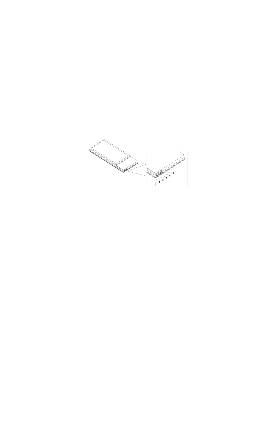
Chapter 4 77
Check the Battery Pack
To check the battery pack, do the following:
From Software:
1. Check out the Power Management in control Panel
2. In Power Meter, confirm that if the parameters shown in the screen for Current Power Source and Total
Battery Power Remaining are correct.
3. Repeat the steps 1 and 2, for both battery and adapter.
4. This helps you identify first the problem is on recharging or discharging.
From Hardware:
1. Power off the computer.
2. Remove the battery pack and measure the voltage between battery terminals 1(+) and 6(ground). See the
following figure
3. If the voltage is still less than 7.5 Vdc after recharging, replace the battery.
To check the battery charge operation, use a discharged battery pack or a battery pack that has less than 50%
of the total power remaining when installed in the computer.
If the battery status indicator does not light up, remove the battery pack and let it return to room temperature.
Re-install the battery pack.
If the charge indicator still does not light up, replace the battery pack. If the charge indicator still does not light
up, replace the DC/DC charger board.
Touchpad Check
If the touchpad doesn’t work, do the following actions one at a time to correct the problem. Do not replace a
non-defective FRU:
1. Reconnect the touchpad cables.
2. Replace the touchpad.
3. Replace the system board.
After you use the touchpad, the pointer drifts on the screen for a short time. This self-acting pointer movement
can occur when a slight, steady pressure is applied to the touchpad pointer. This symptom is not a hardware
problem. No service actions are necessary if the pointer movement stops in a short period of time.

78 Chapter 4
Power-On Self-Test (POST) Error Message
The POST error message index lists the error message and their possible causes. The most likely cause is
listed first.
NOTE: Perform the FRU replacement or actions in the sequence shown in FRU/Action column, if the FRU
replacement does not solve the problem, put the original part back in the computer. Do not replace a
non-defective FRU.
This index can also help you determine the next possible FRU to be replaced when servicing a computer.
If the symptom is not listed, see “Undetermined Problems” on page 87.
The following lists the error messages that the BIOS displays on the screen and the error symptoms classified
by function.
NOTE: Most of the error messages occur during POST. Some of them display information about a hardware
device, e.g., the amount of memory installed. Others may indicate a problem with a device, such as the
way it has been configured.
NOTE: If the system fails after you make changes in the BIOS Setup Utility menus, reset the computer, enter
Setup and install Setup defaults or correct the error.
Chapter 4 79
Index of Error Messages
Error Code List
Error Codes Error Messages
006 Equipment Configuration Error
Causes:
1. CPU BIOS Update Code Mismatch
2. IDE Primary Channel Master Drive Error
(THe causes will be shown before “Equipment Configuration
Error”)
010 Memory Error at xxxx:xxxx:xxxxh (R:xxxxh, W:xxxxh)
070 Real Time Clock Error
071 CMOS Battery Bad
072 CMOS Checksum Error
110 System disabled.
Incorrect password is specified.
<No error code> Battery critical LOW
In this situation BIOS will issue 4 short beeps then shut down
system, no message will show.
<No error code> Thermal critical High
In this situation BIOS will shut down system, not show message.
Error Message List
Error Messages FRU/Action in Sequence
Failure Fixed Disk Reconnect hard disk drive connector.
“Load Default Settings” in BIOS Setup Utility.
Hard disk drive
System board
Stuck Key see “Keyboard or Auxiliary Input Device Check” on page 74.
Keyboard error see “Keyboard or Auxiliary Input Device Check” on page 74.
Keyboard Controller Failed see “Keyboard or Auxiliary Input Device Check” on page 74.
Keyboard locked - Unlock key switch Unlock external keyboard
Monitor type does not match CMOS - Run Setup Run “Load Default Settings” in BIOS Setup Utility.
Shadow RAM Failed at offset: nnnn BIOS ROM
System board
System RAM Failed at offset: nnnn DIMM
System board
Extended RAM Failed at offset: nnnn DIMM
System board
System battery is dead - Replace and run Setup Replace RTC battery and Run BIOS Setup Utility to reconfigure
system time, then reboot system.
System CMOS checksum bad - Default
configuration used
RTC battery
Run BIOS Setup Utility to reconfigure system time, then reboot
system.
System timer error RTC battery
Run BIOS Setup Utility to reconfigure system time, then reboot
system.
System board

80 Chapter 4
Real time clock error RTC battery
Run BIOS Setup Utility to reconfigure system time, then reboot
system.
System board
Previous boot incomplete - Default configuration
used
Run “Load Default Settings” in BIOS Setup Utility.
RTC battery
System board
Memory size found by POST differed from
CMOS
Run “Load Default Settings” in BIOS Setup Utility.
DIMM
System board
Diskette drive A error Check the drive is defined with the proper diskette type in BIOS
Setup Utility
See “External Diskette Drive Check” on page 74.
Incorrect Drive A type - run SETUP Check the drive is defined with the proper diskette type in BIOS
Setup Utility
System cache error - Cache disabled System board
CPU ID: System board
DMA Test Failed DIMM
System board
Software NMI Failed DIMM
System board
Fail-Safe Timer NMI Failed DIMM
System board
Device Address Conflict Run “Load Default Settings” in BIOS Setup Utility.
RTC battery
System board
Allocation Error for device Run “Load Default Settings” in BIOS Setup Utility.
RTC battery
System board
Failing Bits: nnnn DIMM
BIOS ROM
System board
Fixed Disk n None
Invalid System Configuration Data BIOS ROM
System board
I/O device IRQ conflict Run “Load Default Settings” in BIOS Setup Utility.
RTC battery
System board
Operating system not found Enter Setup and see if fixed disk and drive A: are properly identified.
Diskette drive
Hard disk drive
System board
Error Message List
Error Messages FRU/Action in Sequence

Chapter 4 81
Error Message List
No beep Error Messages FRU/Action in Sequence
No beep, power-on indicator turns off and LCD is
blank.
Power source (battery pack and power adapter). See “Power
System Check” on page 75.
Ensure every connector is connected tightly and correctly.
Reconnect the DIMM.
LED board.
System board.
No beep, power-on indicator turns on and LCD is
blank.
Power source (battery pack and power adapter). See “Power
System Check” on page 75.
Reconnect the LCD connector
Hard disk drive
LCD inverter ID
LCD cable
LCD Inverter
LCD
System board
No beep, power-on indicator turns on and LCD is
blank. But you can see POST on an external
CRT.
Reconnect the LCD connectors
LCD inverter ID
LCD cable
LCD inverter
LCD
System board
No beep, power-on indicator turns on and a
blinking cursor shown on LCD during POST.
Ensure every connector is connected tightly and correctly
System board
No beep during POST but system runs correctly. Speaker
System board

82 Chapter 4
POST Code
Code Beeps For Boot Block in Flash ROM
E0h Initialize the chipset
E1h Initialize the bridge
E2h Initialize the CPU
E3h Initialize the system timer
E4h Initialize system I/O
E5h Check force recovery boot
E6h Checksum BIOS ROM
E7h Go to BIOS
E8h Set Huge Segment
E9h Initialize Multi Processor
EAh Initialize OEM special code
EBh Initialize PIC and DMA
ECh Initialize Memory type
EDh Initialize Memory size
EEh Shadow Boot Block
EFh System memory test
F0h Initialize interrupt vectors
F1h Initialize Run Time Clock
F2h Initialize video
F3h Initialize System Management Mode
F4h 1 Output one beep before boot
F5h Boot to Mini DOS
F6h Clear Huge Segment
F7h Boot to Full DOS
Chapter 4 83
Index of Symptom-to-FRU Error Message
LCD-Related Symptoms
Symptom / Error Action in Sequence
LCD backlight doesn't work
LCD is too dark
LCD brightness cannot be adjusted
LCD contrast cannot be adjusted
Enter BIOS Utility to execute “Load Setup Default Settings”, then
reboot system.
Reconnect the LCD connectors.
Keyboard (if contrast and brightness function key doesn't work).
LCD inverter ID
LCD cable
LCD inverter
LCD
System board
Unreadable LCD screen
Missing pels in characters
Abnormal screen
Wrong color displayed
Reconnect the LCD connector
LCD inverter ID
LCD cable
LCD inverter
LCD
System board
LCD has extra horizontal or vertical lines
displayed.
LCD inverter ID
LCD inverter
LCD cable
LCD
System board
Indicator-Related Symptoms
Symptom / Error Action in Sequence
Indicator incorrectly remains off or on, but system
runs correctly
Reconnect the inverter board
Inverter board
System board
Power-Related Symptoms
Symptom / Error Action in Sequence
Power shuts down during operation Power source (battery pack and power adapter). See “Power
System Check” on page 75.
Battery pack
Power adapter
Hard drive & battery connection board
System board
The system doesn’t power-on. Power source (battery pack and power adapter). See “Power
System Check” on page 75.
Battery pack
Power adapter
Hard drive & battery connection board
System board
The system doesn’t power-off. Power source (battery pack and power adapter). See “Power
System Check” on page 75.
Hold and press the power switch for more than 4 seconds.
System board
Battery can’t be charged See “Check the Battery Pack” on page 77.
Battery pack
System board
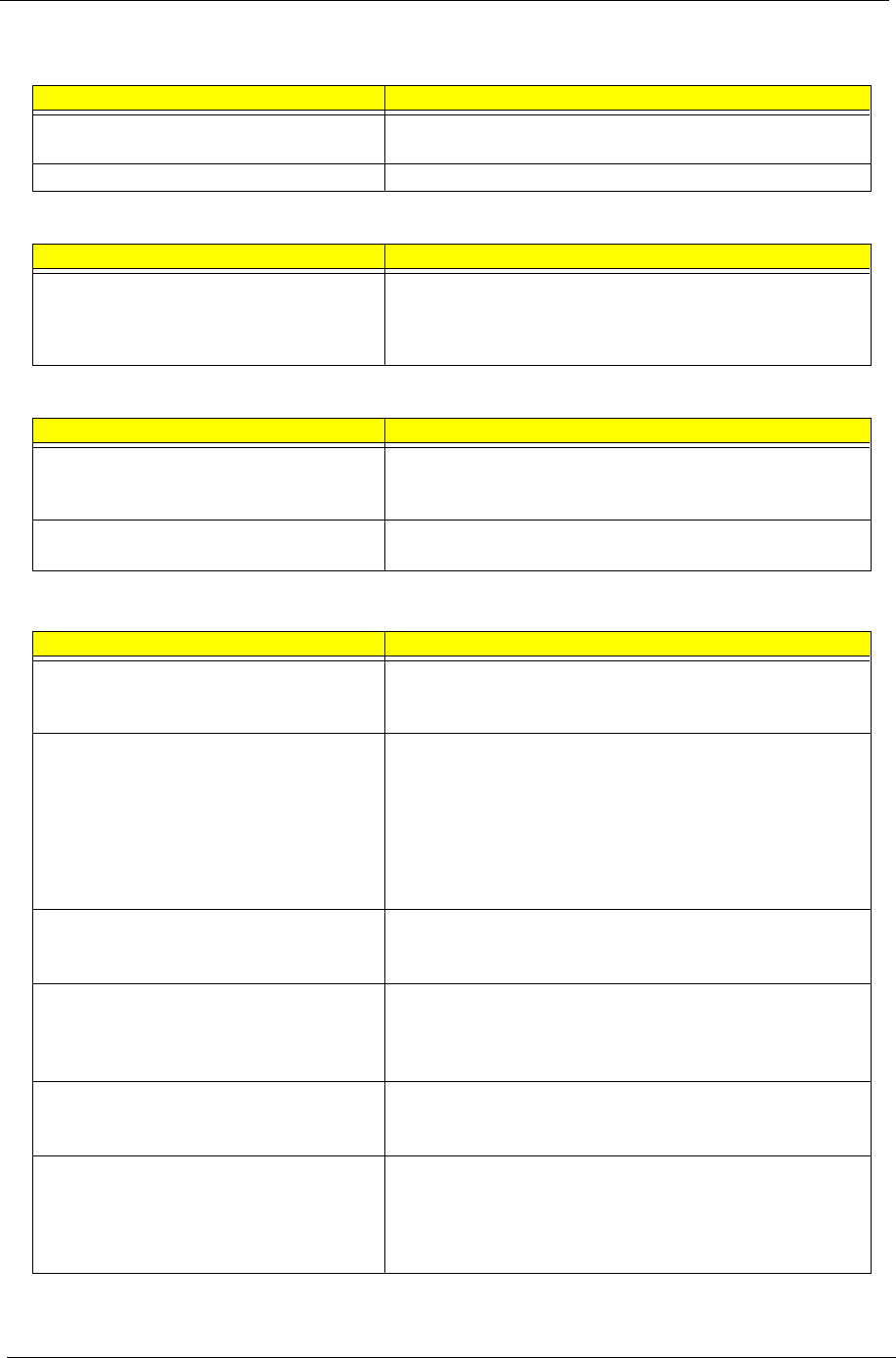
84 Chapter 4
PCMCIA-Related Symptoms
Symptom / Error Action in Sequence
System cannot detect the PC Card (PCMCIA) PCMCIA slot assembly
System board
PCMCIA slot pin is damaged. PCMCIA slot assembly
Memory-Related Symptoms
Symptom / Error Action in Sequence
Memory count (size) appears different from
actual size.
Enter BIOS Setup Utility to execute “Load Default Settings, then
reboot system.
DIMM
System board
Speaker-Related Symptoms
Symptom / Error Action in Sequence
In Windows, multimedia programs, no sound
comes from the computer.
Audio driver
Speaker
System board
Internal speakers make noise or emit no sound. Speaker
System board
Power Management-Related Symptoms
Symptom / Error Action in Sequence
The system will not enter hibernation Keyboard (if control is from the keyboard)
Hard disk drive
System board
The system doesn't enter hibernation mode and
four short beeps every minute.
See “Hibernation Mode” on page 34.
Press Fn+oand see if the computer enters hibernation mode.
Touchpad
Keyboard
Hard disk connection board
Hard disk drive
System board
The system doesn’t enter standby mode after
closing the LCD
See “Hibernation Mode” on page 34.
LCD cover switch
System board
The system doesn't resume from hibernation
mode.
See “Hibernation Mode” on page 34.
Hard disk connection board
Hard disk drive
System board
The system doesn't resume from standby mode
after opening the LCD.
See “Hibernation Mode” on page 34.
LCD cover switch
System board
Battery fuel gauge in Windows doesn’t go higher
than 90%.
Remove battery pack and let it cool for 2 hours
Refresh battery (continue use battery until power off, then charge
battery)
Battery pack
System board
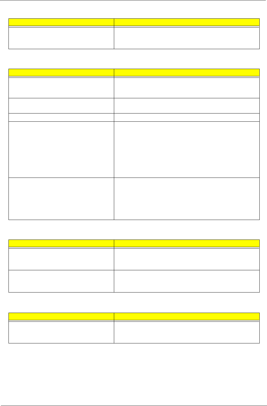
Chapter 4 85
NOTE: If you cannot find a symptom or an error in this list and the problem remains, see “Undetermined
Problems” on page 87.
System hangs intermittently. Reconnect hard disk/CD-ROM drives.
Hard disk connection board
System board
Peripheral-Related Symptoms
Symptom / Error Action in Sequence
System configuration does not match the
installed devices.
Enter BIOS Setup Utility to execute “Load Default Settings”, then
reboot system.
Reconnect hard disk/CD-ROM/diskette drives.
External display does not work correctly. Press Fn+F5, LCD/CRT/Both display switching
System board
USB does not work correctly System board
Print problems. Ensure the “Parallel Port” in the “Onboard Devices Configuration” of
BIOS Setup Utility is set to Enabled.
Onboard Devices Configuration
Run printer self-test.
Printer driver
Printer cable
Printer
System Board
Serial or parallel port device problems. Ensure the “Serial Port” in the Devices Configuration” of BIOS Setup
Utility is set to Enabled.
Device driver
Device cable
Device
System board
Keyboard/Touchpad-Related Symptoms
Symptom / Error Action in Sequence
Keyboard (one or more keys) does not work. Reconnect the keyboard cable.
Keyboard
System board
Touchpad does not work. Reconnect touchpad cable.
Touchpad board
System board
Modem-Related Symptoms
Symptom / Error Action in Sequence
Internal modem does not work correctly. Modem phone port
modem combo board
System board
Power Management-Related Symptoms
Symptom / Error Action in Sequence

86 Chapter 4
Intermittent Problems
Intermittent system hang problems can be caused by a variety of reasons that have nothing to do with a
hardware defect, such as: cosmic radiation, electrostatic discharge, or software errors. FRU replacement
should be considered only when a recurring problem exists.
When analyzing an intermittent problem, do the following:
1. Run the advanced diagnostic test for the system board in loop mode at least 10 times.
2. If no error is detected, do not replace any FRU.
3. If any error is detected, replace the FRU. Rerun the test to verify that there are no more errors.

Chapter 4 87
Undetermined Problems
The diagnostic problems does not identify which adapter or device failed, which installed devices are incorrect,
whether a short circuit is suspected, or whether the system is inoperative.
Follow these procedures to isolate the failing FRU (do not isolate non-defective FRU).
NOTE: Verify that all attached devices are supported by the computer.
NOTE: Verify that the power supply being used at the time of the failure is operating correctly. (See “Power
System Check” on page 75):
1. Power-off the computer.
2. Visually check them for damage. If any problems are found, replace the FRU.
3. Remove or disconnect all of the following devices:
TNon-Acer devices
TPrinter, mouse, and other external devices
TBattery pack
THard disk drive
TDIMM
TCD-ROM/Diskette drive Module
TPC Cards
4. Power-on the computer.
5. Determine if the problem has changed.
6. If the problem does not recur, reconnect the removed devices one at a time until you find the failing FRU.
7. If the problem remains, replace the following FRU one at a time. Do not replace a non-defective FRU:
TSystem board
TLCD assembly
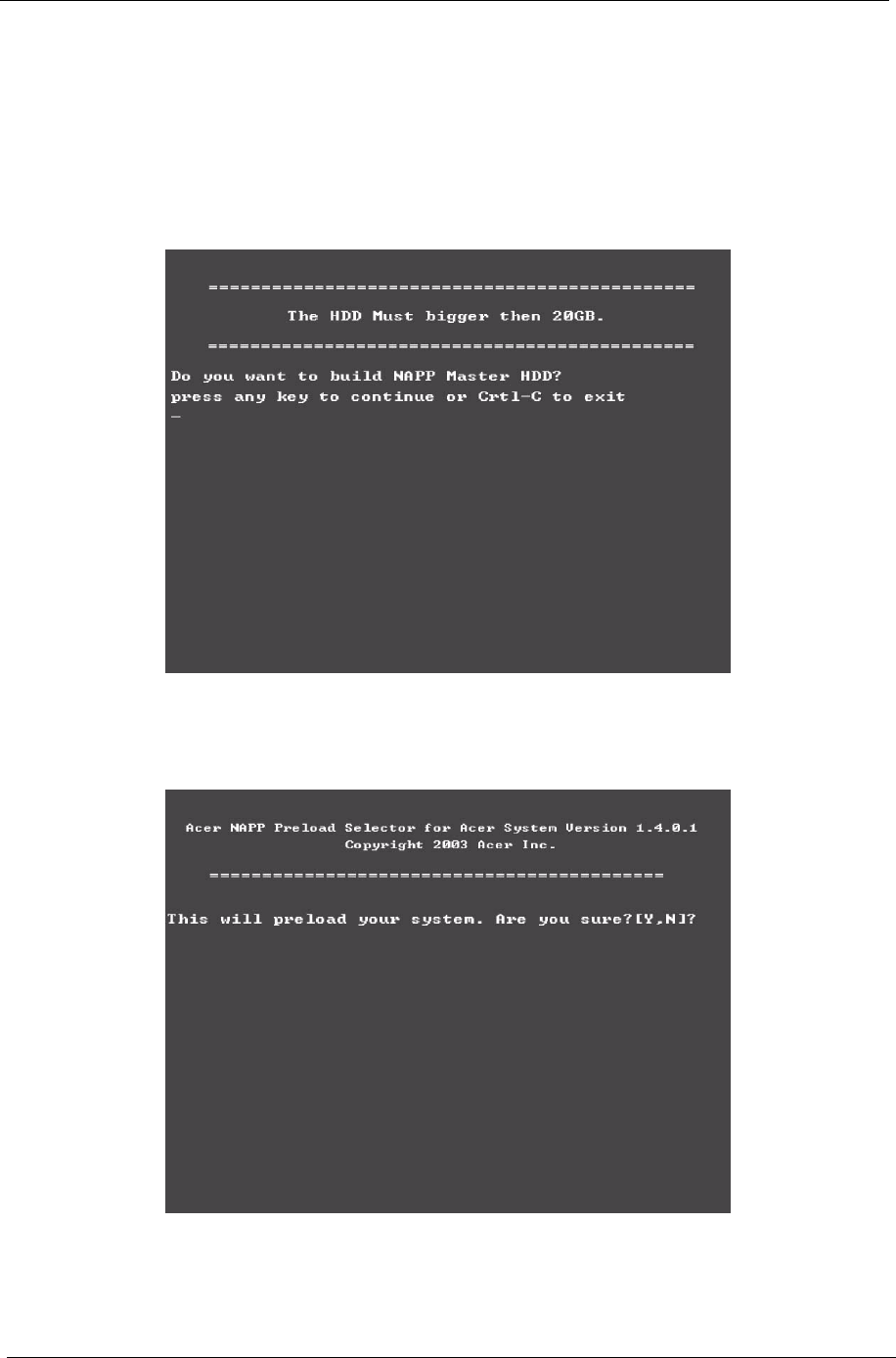
88 Chapter 4
Use NAPP CD to Build Master Hard Disc Drive
CD to Disk Recovery
1. Prepare NAPP CD, Recovery CD and System CD.
2. Put NAPP CD into the optical drive. Then boot up the system.
3. The system will ask you if you want to build NAPP Master HDD. Please press any key to continue.
4. NAPP CD will start to preload the system, please click [Y].
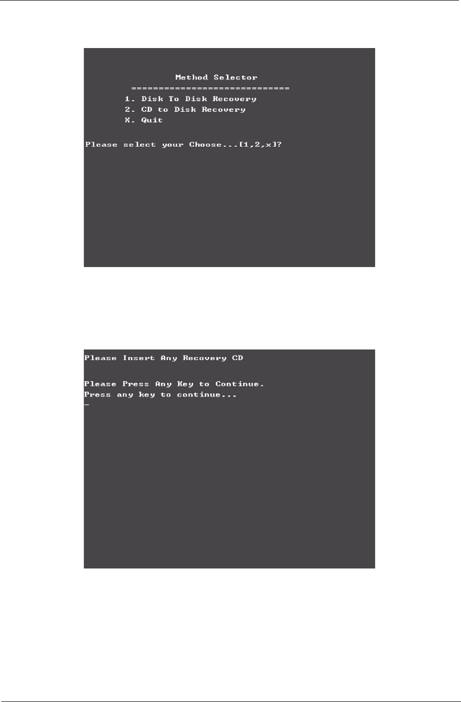
Chapter 4 89
5. Select CD to Disk Revocery.
6. Put the Recovery CD to the optical drive. This step is to create image files to the system, you do not have
to put the Recovery CD to the optical drive in order. Place one Recovery CD to the drive at one time till
you finish all Recovery CDs.
After you place the Recovery CD to the optical drive, you will see the display below.
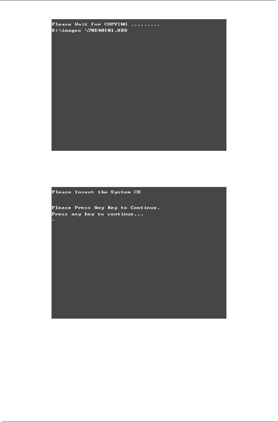
90 Chapter 4
7. Then insert the System CD to the optical drive.
8. You will see the screen displaying “PASS” when the system has buit NAPP Master hard disc drive.
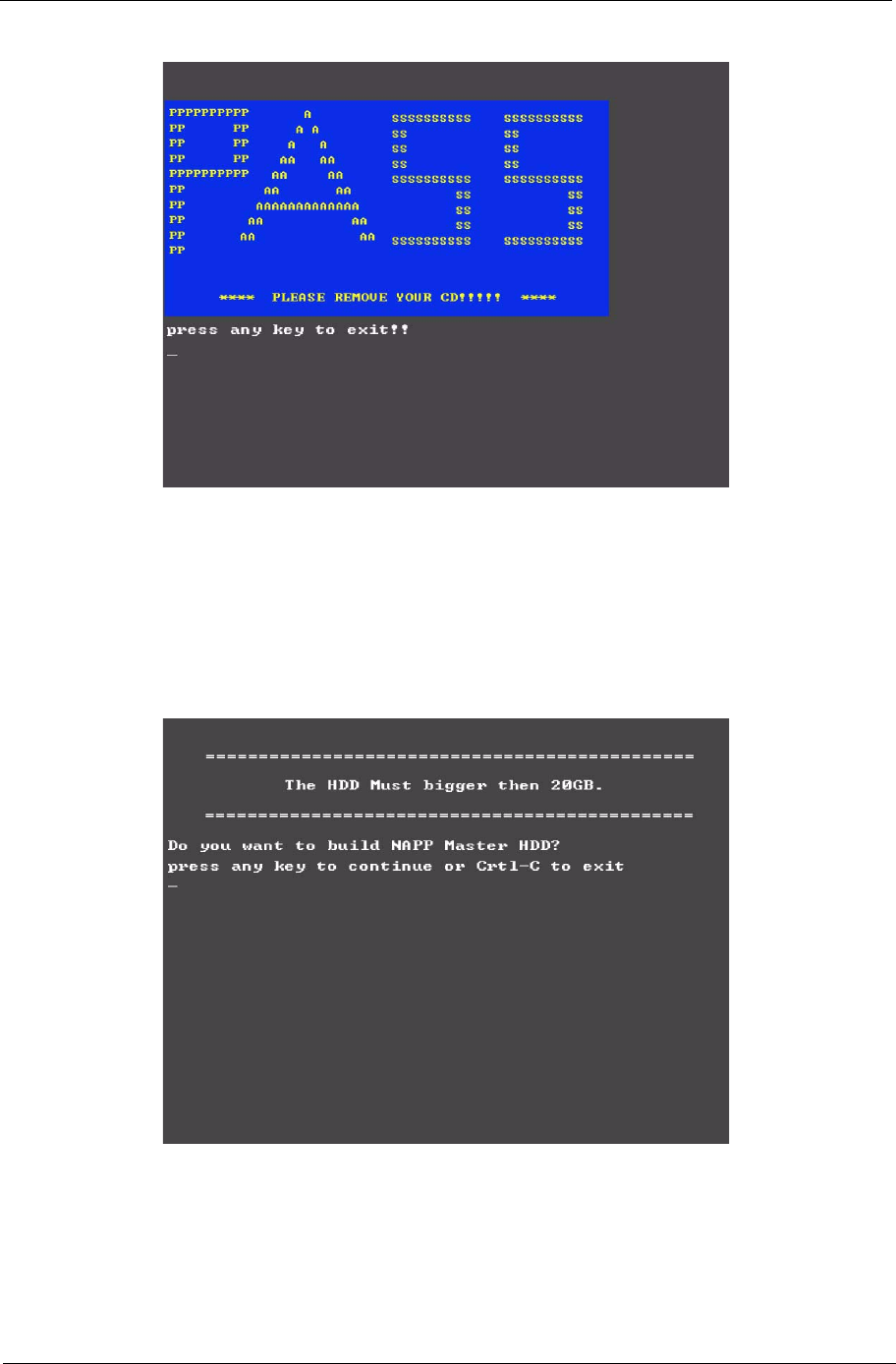
Chapter 4 91
Disk to Disk Recovery
1. Prepare NAPP CD, Recovery CD and System CD.
2. Put NAPP CD into the optical drive. Then boot up the system.
3. The system will ask you if you want to build NAPP Master HDD. Please press any key to continue.
4. NAPP CD will start to preload the system, please click [Y].
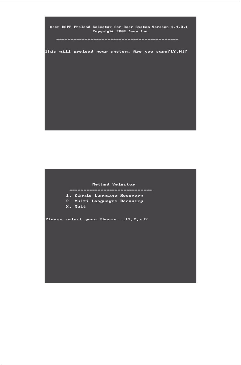
92 Chapter 4
5. Select Disk to Disk Recovery. Then choose Single Language or Multi-Languages Recovery.
NOTE: For Multi-Languages Recovery, not more than five languages could be loaded to the system.
6. Put the Recovery CD to the optical drive. This step is to create image files to the system, you do not have
to put the Recovery CD to the optical drive in order. Place one Recovery CD to the drive at one time till
you finish all Recovery CDs.
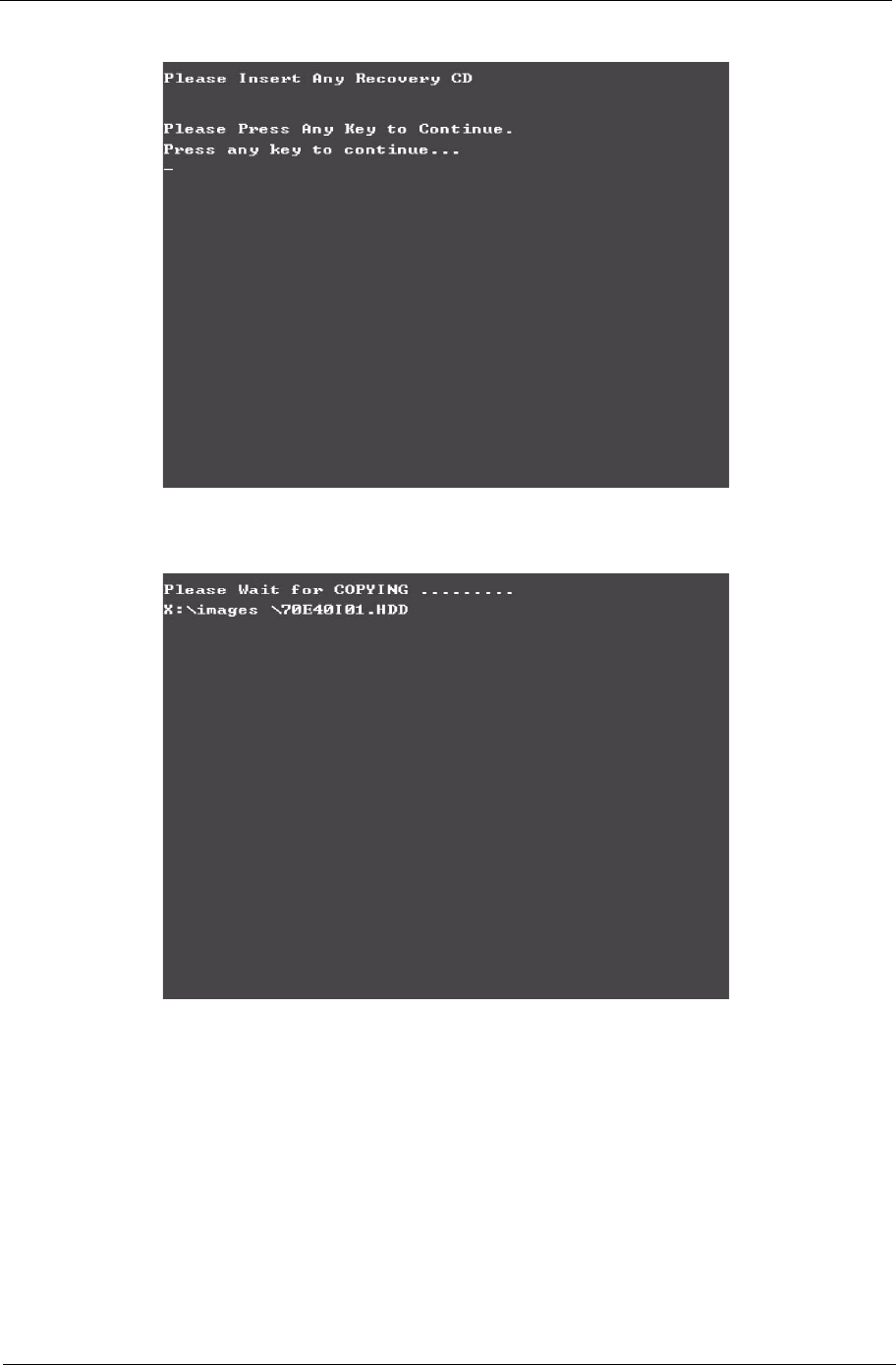
Chapter 4 93
After you place the Recovery CD to the optical drive, you will see the display below.
7. Then insert the System CD to the optical drive.
94 Chapter 4
8. You will see the screen displaying “PASS” when the system has buit NAPP Master hard disc drive.
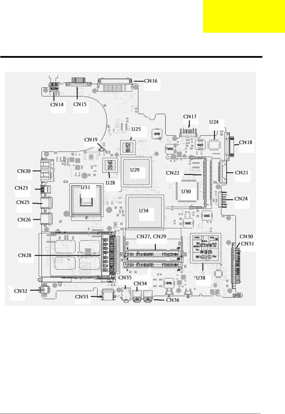
Chapter 5 95
Top View
Jumper and Connector Locations
Chapter 5
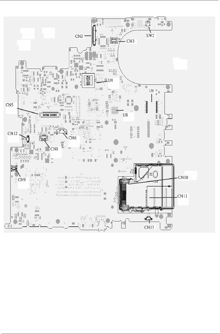
96 Chapter 5
Rear View

Chapter 5 97
ITEM DESCRIPTION ITEM DESCRIPTION
CN2 LCD Connector CN14 DC JACK
CN3 LED board connector CN15 CRT connector
SW2 Lid switch CN16 Docking connector
CN10 express card connector CN17 Battery connector
CN11 4 IN 1 connector CN18 Fix ODD connector
CN13 Speaker connector CN21 Swap ODD connector
CN9 MD board connector CN24 2nd Battery connector
CN12 INT MIC connector CN30 PATA HDD connector
CN5 Keyboard connector CN31 SATA HDD connector
CN6 BT connector CN36 Line IN connector
CN8 TP connector CN34 MIC IN connector
U4 VGA RAM CN35 Line out/SPDIF
connector
U8 VGA RAM CN33 USB connector
U6 LAN transformer CN32 1394 connector
CN28 PCMCIA connector CN26 USB connector
CN25 USB connector CN23 S video connector
CN20 RJ45/RJ11 connector CN19 Fan connector
CN22 MINI PCI connector U31 CPU
U30 EC U29 VGA Chp
U34 North Bridge U38 South Bridge
U25 VGA RAM U28 VGA RAM
U24 BIOS ROM
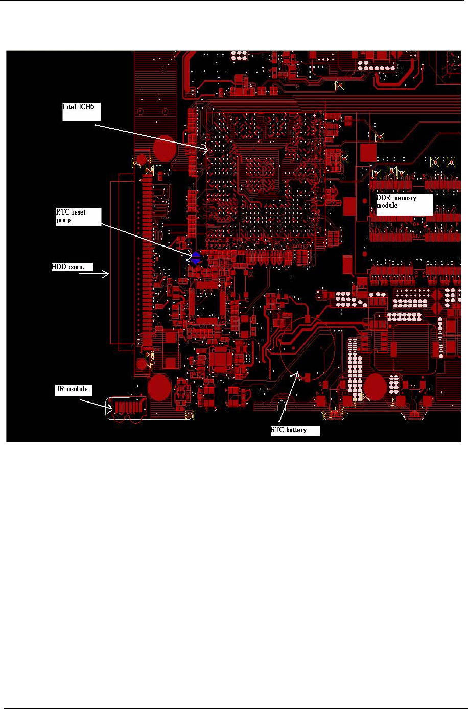
98 Chapter 5
RTC Jumper

Chapter 6 99
This chapter gives you the FRU (Field Replaceable Unit) listing in global configurations of Aspire 1690 and
Aspire 3510. Refer to this chapter whenever ordering for parts to repair or for RMA (Return Merchandise
Authorization).
Please note that WHEN ORDERING FRU PARTS, you should check the most up-to-date information available
on your regional web or channel. For whatever reasons a part number change is made, it will not be noted on
the printed Service Guide. For ACER AUTHORIZED SERVICE PROVIDERS, your Acer office may have a
DIFFERENT part number code from those given in the FRU list of this printed Service Guide. You MUST use
the local FRU list provided by your regional Acer office to order FRU parts for repair and service of customer
machines.
NOTE: To scrap or to return the defective parts, you should follow the local government ordinance or
regulations on how to dispose it properly, or follow the rules set by your regional Acer office on how to
return it.
FRU (Field Replaceable Unit) List
Chapter 6
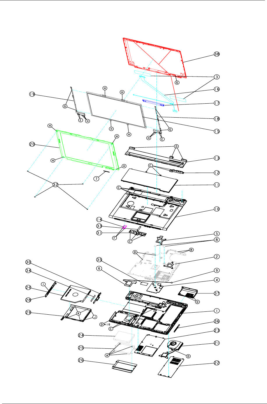
100 Chapter 6
Exploded Diagram
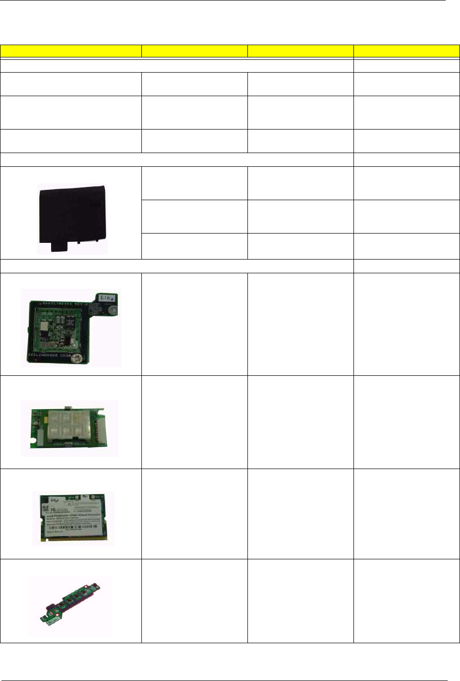
Chapter 6 101
Illustration Part Name Description Acer P/N
Adapter
ADAPTER 65W 3 PIN
DELTA SADP-65KB BFD
TBD AP.06501.005
ADAPTER 65W 3 PIN
LITE-ON PA-1650-02 Q2
19V
TBD AP.06503.006
ADAPTER 65W 3 PIN
HIPRO HP-OK066B13QT
TBD AP.06506.001
Battery
BATTERY SANYO LI-ION
4S2P 4.4A 4UR18650F-2-
QC140
ZL1A BATTERY (SANYO
8 CELL) S.P.
BT.T5003.001
BATTERY PANASONIC
LI-ION 4S2P 4.4A CGR-
B/8B5AE
ZL1A BATTERY
(PANASONIC 8 CELL)
S.P
BT.T5005.001
BATTERY SIMPLO LI-
ION 4S2P 4.4A 916-3020
ZL1A BATTERY (SIMPLO
8 CELL) S.P.
BT.T5007.001
Board
MODEM BOARD ZL1A MODEM BOARD
ASSY S.P.
54.T50V7.001
BLUETOOTH MODULE
W/ANTENNA
ZA1 BLUETOOTH
MODULE S/P (WITH BT
ANTENNA)
54.T48V7.001
WIRELESS LAN BOARD
(802.11b+g) INTEL
ZG1S 802.11b+g SPARE
PART-Intel
KI.CAX01.008
LAUNCH BOARD ZL1A LEB BOARD ASY
S.P.
55.T50V7.001
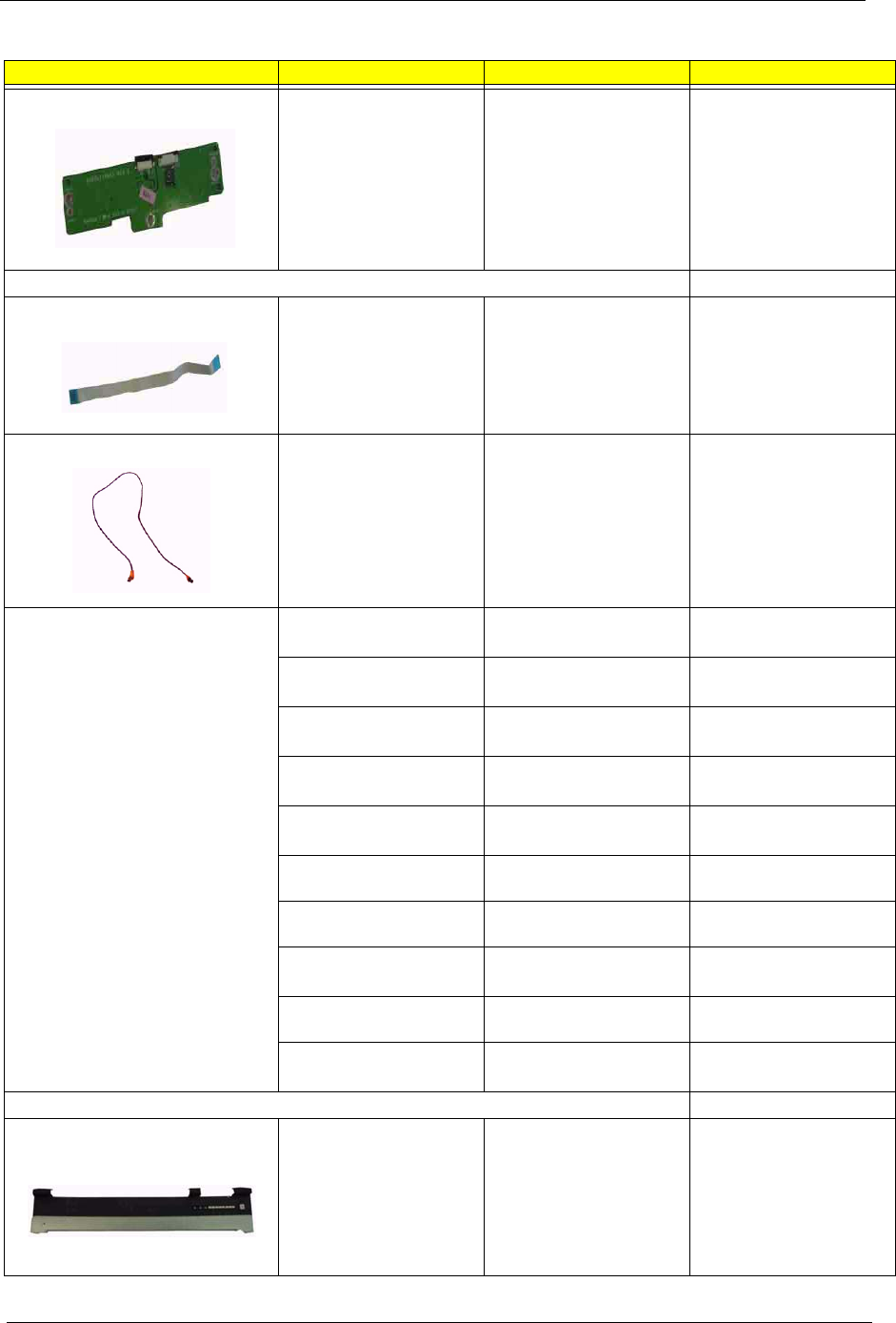
102 Chapter 6
TOUCH PAD BOARD ZL1A TOUCH PAD
BOARD ASSY S.P.
55.T50V7.002
Cable
FFC CABLE - TP/B TO
MB
ZL1A TOUCH PAD
BOARD M/B (FFC) ASSY
S.P.
50.T50V7.001
MODEM CABLE ZL1A MODEM CABLE
ASSY S.P.
50.T50V7.002
POWER CORD US
(3 PIN)
ET2S POWER CORD S/
P-US
27.A03V7.001
POWER CORD PRC
(3 PIN)
ET2S POWER CORD S/
P-PRC
27.A03V7.003
POWER CORD KOERA
( 3 Pin)
ZI1S POWER CORD
SPARE PART-KOERA
27.T23V7.006
POWER CORD EU
(3 PIN)
ET2S POWER CORD S/
P-EU
27.A03V7.002
POWER CORD UK
(3 PIN)
ET2S POWER CORD S/
P-UK
27.A03V7.004
POWER CORD ITALIAN
(3 PIN)
ET2S POWER CORD S/
P-ITALIAN
27.A03V7.005
POWER CORD- SWISS ET2S POWER CORD
SPARE PART-SWISS
27.A03V7.007
POWER CORD AU
(3 PIN)
ET2S POWER CORD S/
P-AU
27.A03V7.008
POWER CORD DANISH
(3 PIN)
ET2S POWER CORD S/
P-DANISH
27.A03V7.006
POWER CORD AF
(3 PIN)
ZI5 POWER CORD S/P-
AF
27.T48V7.001
Case/Cover/Bracket Assembly
MIDDEL COVER ERGO
W/BUTTON - LIGHT
GREEN SILVER
ZL1 KB LCD COVER-TM-
NEW ASSY
42.T50V7.101
Illustration Part Name Description Acer P/N
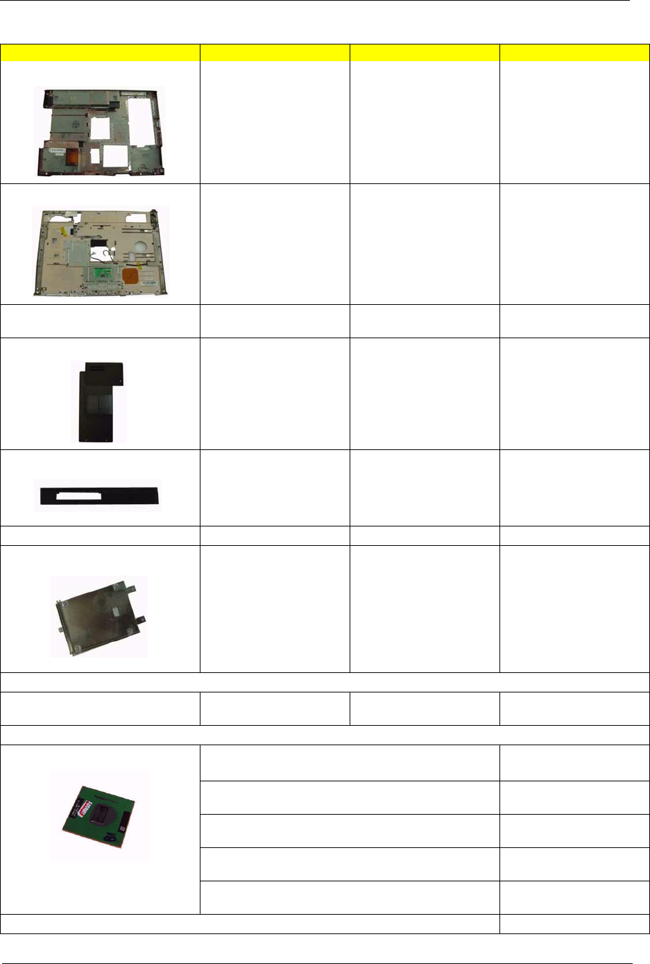
Chapter 6 103
LOWER CASE FOR
SWAP W/SPEAKER
ZL2 BASE ASSY W/
MEDIA BAY S/P
60.T63V7.001
UPPER CASE W/
TOUCHPAD, BRACKET,
MIC,BLUETOOTH
CABLE
ZL2 TOP COVER TM
ASSY CONDUCT PAINT
60.T63V7.002
DIMM/WIRELESS
COVER
ZL1 DDR COVER ASSY 42.T63V7.001
HEATSINK COVER W/
DOCKING
ZL2 HEATSINK COVER
W/DOCKING ASSY
42.T63V7.002
3 IN 1 COVER ZL2 3 IN 1 COVER ASSY
S.P.
42.T63V7.003
HDD COVER ZL2 HDD COVER ASSY 42.T63V7.004
HDD BRACKET ZL1A HDD BRACKET
ASSY S.P.
33.T50V7.001
Communication Module
WIRELESS LAN
ANTENNA
ZL1A WIRELESS
ANTENNA ASSY S.P.
50.T50V7.003
CPU/Processor
INTEL PENTIUM M 1.5G 2M 400FSB uFCPGA2 SL6F9
B-1 STEPPING
KC.N0001.715
INTEL PENTIUM M 1.6G 2M 400FSB uFCPGA2 SL7EG
B-1 STEPPING
KC.N0001.725
INTEL PENTIUM M 1.7G 2M 400FSB uFCPGA2 SL7EP
B-1 STEPPING
KC.N0001.735
INTEL PENTIUM M 1.8G 2M 400FSB uFCPGA2 SL7EN
B-1 STEPPING
KC.N0001.745
INTEL PENTIUM M 2.0G 2M 400FSB uFCPGA2 SL7EM
B-1 STEPPING
KC.N0001.755
Optical Disk Drive Module
Illustration Part Name Description Acer P/N
104 Chapter 6
DVD/CDRW COMBO
MODULE 24X QSI SBW-
242C SWAP
ZL1 COMBO (QSI SBW-
242C) W/MB ASSY S.P.
6M.T50V7.001
DVD/CDRW COMBO
DRIVE 24X QSI SBW-
242C
ZI6 COMBO SBW-242C
S/P-QSI
KO.02407.014
OPTICAL DEVICE
CONNECTOR BOARD
W/MYLARY
ZL1 CD ROM/B ASSY
S.P.
55.T50V7.003
OPTICAL DEVICE
HOLDER-SWAP
ZL1 DVD HOLDER ASSY
S.P.
42.T50V7.007
DVD/CDRW BEZEL FOR
QSI
ZL1A COMBO BEZEL
(QSI) ASSY S.P.
42.T50V7.008
DVD/CDRW COMBO
MODULE KME UJDA-760
SWAP
ZL1 COMBO (KME
UJDA-760) W/MB ASSY
S.P.
6M.T50V7.002
DVD/CDRW COMBO
DRIVE 24X KME UJDA-
760
ZL1A COMBO (KME
UJDA-760) S.P.
KO.02406.008
OPTICAL DEVICE
CONNECTOR BOARD
W/MYLARY
ZL1 CD ROM/B ASSY
S.P.
55.T50V7.003
OPTICAL DEVICE
HOLDER-SWAP
ZL1 DVD HOLDER ASSY
S.P.
42.T50V7.007
DVD/CDRW BEZEL FOR
KME
ZL1A COMBO BEZEL
(KME) ASSY S.P.
42.T50V7.009
DVD DUAL MODULE QSI
SDW-082 SWAP
ZL2 DVD DUAL (QSI
SDW-082) W/MB ASSY
S/P
TBD
DVD DUAL DRIVE QSI
SDW-082 F/W : ?
ZL1A DVD DUAL (QSI
SDW-082) S.P.
TBD
OPTICAL DEVICE
CONNECTOR BOARD
W/MYLARY
ZL1 CD ROM/B ASSY
S.P.
55.T50V7.003
OPTICAL DEVICE
HOLDER-SWAP
ZL1 DVD HOLDER ASSY
S.P.
42.T50V7.007
DVD DUAL BEZEL FOR
QSI
ZL1A DVD DUAL BEZEL
(QSI) ASSY S.P.
42.T50V7.010
DVD DUAL MODULE
PIONEER DVR-K14RA
SWAP
ZL2 DVD DUAL(PIO
DVR-K14RA)W/MB ASSY
S/P
TBD
DVD DUAL DRIVE
PIONEER DVR-K14RA F/
W : ?
ZL1A DVD DUAL (PIO
DVR-K14RA) S.P.
TBD
OPTICAL DEVICE
CONNECTOR BOARD
W/MYLARY
ZL1 CD ROM/B ASSY
S.P.
55.T50V7.003
OPTICAL DEVICE
HOLDER-SWAP
ZL1 DVD HOLDER ASSY
S.P.
42.T50V7.007
DVD DUAL BEZEL FOR
PIONEER
ZL1A DVD DUAL BEZEL
(PIO) ASSY S.P.
42.T50V7.011
DVD DUAL MODULE
LITE-ON SOSW-813
SWAP
ZL2 DVD DUAL(LTN
SOSW-813)W/MB ASSY
S/P
TBD
Illustration Part Name Description Acer P/N
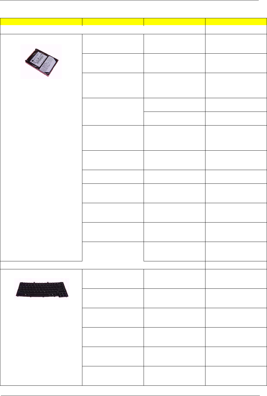
Chapter 6 105
HDD/Hard Disk Drive
Toshiba PLUTO 40G
4200rpm MK4025GAS
,KA100A F/W:KA100A
Toshiba PLUTO 40G
4200rpm MK4025GAS
,KA100A F/W:KA100A
KH.04004.002
SEAGATE 40G 4200rpm
ST94019A, 2MB F/
W:3.05
SEAGATE 40G 4200rpm
ST94019A, 2MB F/
W:3.05
KH.04001.010
TOSHIBA PLUTO 60GB
4200RPM, MK6025GAS
HGST MORAGA 60GB
4200RPM,
IC25N060ATMR04-0
08K0634
KH.06007.006
TOSHIBA PLUTO 60GB
4200RPM, MK6025GAS
TOSHIBA PLUTO 60GB
4200RPM, MK6025GAS
KH.06004.003
SEAGATE N2 (50) 60GB
4200RPM, ST960821A
SEAGATE N2 (50) 60GB
4200RPM, ST960821A
KH.06001.002
HGST MORAGA 80GB
4200RPM,
IC25N080ATMR04-0
08K635
HGST MORAGA 80GB
4200RPM,
IC25N080ATMR04-0
08K635
KH.08007.007
TOSHIBA PLUTO 80GB
4200RPM, MK8025GAS,
8MB
TOSHIBA PLUTO 80GB
4200RPM, MK8025GAS,
8MB
KH.08004.001
SEAGATE N2 (50) 80GB
4200RPM, ST9808210A
SEAGATE N2 (50) 80GB
4200RPM, ST9808210A
KH.08001.012
TOSHIBA PROTEUS
60GB 5400RPM,
MK6026GAX PA202G
TOSHIBA PROTEUS
80GB 5400RPM,
MK8026GAX
KH.06004.002
HGST MORAGA+ 60GB
5400RPM,
HTS541060G9AT00 A56J
HGST MORAGA+ 60GB
5400RPM,
HTS541060G9AT00
KH.06007.008
HGST MORAGA+ 80GB
5400RPM,
HTS541080G9AT00
HGST MORAGA+ 80GB
5400RPM,
HTS541080G9AT00
KH.08007.009
TOSHIBA PROTEUS
80GB 5400RPM,
MK8026GAX
TOSHIBA PROTEUS
80GB 5400RPM,
MK8026GAX
KH.08004.002
Keyboard
TM4500/TM4000/TM2300
KEYBOARD DARFON
US International
ZL1A K/B EUGO-U/I
ASSY S.P.
KB.T5007.001
TM4500/TM4000/TM2300
KEYBOARD DARFON
Chinese
ZL1A K/B ERGO-TAIWAN
ASSY S.P.
KB.T5007.002
TM4500/TM4000/TM2300
KEYBOARD DARFON
Spanish
ZL1A K/B EUGO-
SPANISH ASSY S.P.
KB.T5007.003
TM4500/TM4000/TM2300
KEYBOARD DARFON
Thai
ZL1A K/B EUGO-THAI
ASSY S.P.
KB.T5007.004
TM4500/TM4000/TM2300
KEYBOARD DARFON
Brazilian Protugese
ZL1A K/B EUGO-BRAZ
PROTUG ASSY S.P.
KB.T5007.005
TM4500/TM4000/TM2300
KEYBOARD DARFON
Korea
ZL1A K/B EUGO-KOREA
ASSY S.P.
KB.T5007.006
Illustration Part Name Description Acer P/N

106 Chapter 6
TM4500/TM4000/TM2300
KEYBOARD DARFON
UK
ZL1A K/B EUGO-U/I
U.K.ASSY S.P.
KB.T5007.007
TM4500/TM4000/TM2300
KEYBOARD DARFON
German
ZL1A K/B EUGO-
GERMAN ASSY S.P.
KB.T5007.008
TM4500/TM4000/TM2300
KEYBOARD DARFON
Italian
ZL1A K/B EUGO-ITALIAN
ASSY S.P.
KB.T5007.009
TM4500/TM4000/TM2300
KEYBOARD DARFON
French
ZL1A K/B EUGO-
FRENCH ASSY S.P.
KB.T5007.010
TM4500/TM4000/TM2300
KEYBOARD DARFON
Swiss/G
ZL1A K/B EUGO-SWISS/
G ASSY S.P.
KB.T5007.011
TM4500/TM4000/TM2300
KEYBOARD DARFON
Portuguese
ZL1A K/B EUGO-
PORTUG ASSY S.P.
KB.T5007.012
TM4500/TM4000/TM2300
KEYBOARD DARFON
Arabic
ZL1A K/B EUGO-ARABIC
ASSY S.P.ZL1A K/B
EUGO-ARABIC ASSY
S.P.
KB.T5007.013
TM4500/TM4000/TM2300
KEYBOARD DARFON
Belgium
ZL1A K/B EUGO-
BELGIUM ASSY S.P.
KB.T5007.014
TM4500/TM4000/TM2300
KEYBOARD DARFON
Sweden
ZL1A K/B EUGO-
SWEDEN ASSY S.P.
KB.T5007.015
TM4500/TM4000/TM2300
KEYBOARD DARFON
Czech
ZL1A K/B EUGO-CZECH
ASSY S.P.
KB.T5007.016
TM4500/TM4000/TM2300
KEYBOARD DARFON
Hungaian
ZL1A K/B EUGO-HUNG
ASSY S.P.
KB.T5007.017
TM4500/TM4000/TM2300
KEYBOARD DARFON
Norway
ZL1A K/B EUGO-
NORWAY ASSY S.P.
KB.T5007.018
TM4500/TM4000/TM2300
KEYBOARD DARFON
Danish
ZL1A K/B EUGO-DANISH
ASSY S.P.
KB.T5007.019
TM4500/TM4000/TM2300
KEYBOARD DARFON
Turkish
ZL1A K/B EUGO-
TURKISH ASSY S.P.
KB.T5007.020
TM4500/TM4000/TM2300
KEYBOARD DARFON
Canadian French
ZL1A K/B EUGO-CANA
FREN ASSY S.P.
KB.T5007.021
TM4500/TM4000/TM2300
KEYBOARD DARFON
Japanese
ZL1A K/B EUGO-JAPAN
ASSY S.P.
KB.T5007.022
TM4500/TM4000/TM2300
KEYBOARD DARFON
Greek
ZL1A K/B EUGO-GREEK
ASSY S.P.
KB.T5007.023
TM4500/TM4000/TM2300
KEYBOARD DARFON
Hebrew
ZL1A K/B EUGO-
HEBREW ASSY S.P.
KB.T5007.024
TM4500/TM4000/TM2300
KEYBOARD DARFON
Russian
ZL1A K/B EUGO-RUSS
ASSY S.P.
KB.T5007.025
Illustration Part Name Description Acer P/N
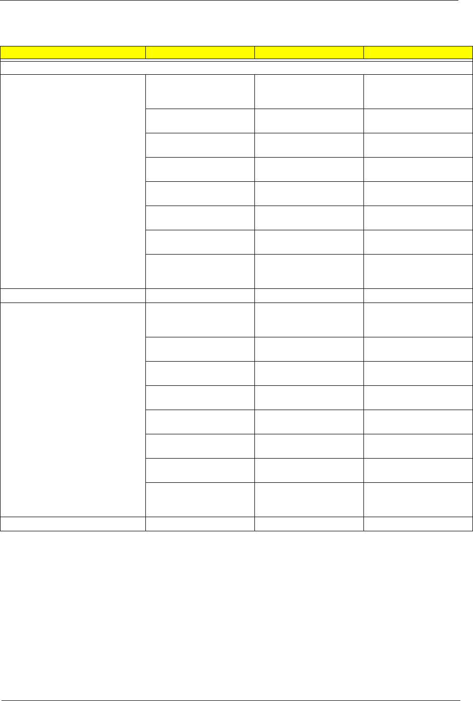
Chapter 6 107
Illustraion Item Description Acer P/N
LCD
LCD MODULE 15 IN. SXGA
CMO N150P2-L04 - LIGHT
GREEN SILIVER
ZL1 15" LCD SXGA+ (TM-
CMO) ASSY S.P. NEW
COLOR
6M.T50V7.026
LCD 15" TFT SXGA+ CMO
N150P2-L04
ZI3 15" SXGA LCD S/P-
CMO
LK.1500D.003
LCD INVERTER BOARD ZL1A LCD INVERTER
ASSY S.P.
19.T50V7.001
LCD CABLE - 15 IN. SXGA ZL1 15" LCD CABLE
SXGA+ ASSY S.P.
50.T50V7.005
LCD BRACKET W/HINGE
15 IN. - L
ZL1A 15" LCD HINGE (L)
ASSY S.P.
33.T50V7.002
LCD BRACKET W/HINGE
15 IN. - R
ZL1A 15" LCD HINGE (R)
ASSY S.P.
33.T50V7.003
LCD BEZEL W/RUBBER
PAD 15 IN.
ZL1A 15" LCD BEZEL
ASSY S.P.
60.T50V7.004
LCD PANEL W/LOGO
ANTENNA 14/15 IN.- LIGHT
GREEN SILVER
ZL1A 14/15" LCD COVER
TM ASSY S.P. NEW
COLOR
60.T50V7.102
LCD MODULE 15 IN. SXGA
AU B150PG03 -LIGHT
GREEN SILVER
ZL1 15" LCD SXGA+ (TM-
AU) ASSY S.P. NEW
COLOR
6M.T63V7.011
LCD 15" TFT SXGA+ AU
B150PG03 (NOVATEC)
ZI1S 15" SXGA+ LCD
PANEL S/P-AU
LK.15005.008
LCD INVERTER BOARD ZL1A LCD INVERTER
ASSY S.P.
19.T50V7.001
LCD CABLE - 15 IN. SXGA ZL1 15" LCD CABLE
SXGA+ ASSY S.P.
50.T50V7.005
LCD BRACKET W/HINGE
15 IN. - L
ZL1A 15" LCD HINGE (L)
ASSY S.P.
33.T50V7.002
LCD BRACKET W/HINGE
15 IN. - R
ZL1A 15" LCD HINGE (R)
ASSY S.P.
33.T50V7.003
LCD BEZEL W/RUBBER
PAD 15 IN.
ZL1A 15" LCD BEZEL
ASSY S.P.
60.T50V7.004
LCD PANEL W/LOGO
ANTENNA 14/15 IN.- LIGHT
GREEN SILVER
ZL1A 14/15" LCD COVER
TM ASSY S.P. NEW
COLOR
60.T50V7.102
108 Chapter 6
LCD MODULE 15 IN. SXGA
SAMSUNG LTN150P4-L03 -
LIGHT GREEN SILVER
ZL1 15" LCD SXGA+(TM-
SAM) ASSY S.P. NEW
CO;OR
6M.T50V7.028
LCD 15 IN. TFT SXGA+
SAMSUNG LTN150P4-L03
(150nit)
ZI6 15" SXGA+ LCD S/P-
SAMSUNG
LK.15006.006
LCD INVERTER BOARD ZL1A LCD INVERTER
ASSY S.P.
19.T50V7.001
LCD CABLE - 15 IN. SXGA ZL1 15" LCD CABLE
SXGA+ ASSY S.P.
50.T50V7.005
LCD BRACKET W/HINGE
15 IN. - L
ZL1A 15" LCD HINGE (L)
ASSY S.P.
33.T50V7.002
LCD BRACKET W/HINGE
15 IN. - R
ZL1A 15" LCD HINGE (R)
ASSY S.P.
33.T50V7.003
LCD BEZEL W/RUBBER
PAD 15 IN.
ZL1A 15" LCD BEZEL
ASSY S.P.
60.T50V7.004
LCD PANEL W/LOGO
ANTENNA 14/15 IN.- LIGHT
GREEN SILVER
ZL1A 14/15" LCD COVER
TM ASSY S.P. NEW
COLOR
60.T50V7.102
LCD MODULE 15.4 IN.
WXGA QDI QD15TL02-01-
LIGHT GREEN SILVER
ZL1A 15.4" LCD WXGA (TM
QDI) ASSY S.P. NEW
COLOR
6M.T50V7.029
LCD 15.4 IN. WXGA QDI
QD15TL02-01
ZL1A 15.4" LCD (QDI)
PANEL ASSY S.P.
LK.15409.001
LCD INVERTER BOARD ZL1A LCD INVERTER
ASSY S.P.
19.T50V7.001
LCD CABLE - 15.4 IN.
WXGA
ZL1A 15.4" LCD WXGA
CABEL ASSY S.P.
50.T50V7.006
LCD BRACKET W/HINGE
15.4 IN. - L
ZL1A 15.4" LCD HINGE (L)
ASSY S.P.
33.T50V7.004
LCD BRACKET W/HINGE
15.4 IN. - R
ZL1A 15.4" LCD HINGE (R)
ASSY S.P.
33.T50V7.005
LCD BEZEL W/RUBBER
PAD 15.4 IN.
ZL1A 15.4" LCD BEZEL
ASSY S.P.
60.T50V7.006
LCD PANEL W/LOGO
ANTENNA 15.4 IN.- LIGHT
GREEN SILVER
ZL1A 15.4" LCD (TM)
COVER ASSY S.P. NEW
COLOR
60.T50V7.103
Illustraion Item Description Acer P/N
Chapter 6 109
LCD MODULE 15.4 IN.
WXGA LG LP154W01-A5 1-
LIGHT GREEN SILVER
ZL2 15.4" LCD WXGA (TM
LG) ASSY S.P. NEW
COLOR
6M.T63V7.012
LCD 15.4 IN. WXGA LG
LP154W01-A5
ZL2 15.4" LCD (LG) PANEL
ASSY S.P.
LK.15408.005
LCD INVERTER BOARD ZL1A LCD INVERTER
ASSY S.P.
19.T50V7.001
LCD CABLE - 15.4 IN.
WXGA
ZL1A 15.4" LCD WXGA
CABEL ASSY S.P.
50.T50V7.006
LCD BRACKET W/HINGE
15.4 IN. - L
ZL1A 15.4" LCD HINGE (L)
ASSY S.P.
33.T50V7.004
LCD BRACKET W/HINGE
15.4 IN. - R
ZL1A 15.4" LCD HINGE (R)
ASSY S.P.
33.T50V7.005
LCD BEZEL W/RUBBER
PAD 15.4 IN.
ZL1A 15.4" LCD BEZEL
ASSY S.P.
60.T50V7.006
LCD PANEL W/LOGO
ANTENNA 15.4 IN.- LIGHT
GREEN SILVER
ZL1A 15.4" LCD (TM)
COVER ASSY S.P. NEW
COLOR
60.T50V7.103
LCD MODULE 15.4 IN.
WXGA CMO N154I1-L09
V.C2-LIGHT GREEN
SILVER
ZL2 15.4" LCD WXGA (TM
CMO) ASSY S.P. NEW
COLOR
6M.T63V7.013
LCD 15.4 IN. WXGA CMO
N154I1-L09 V.C2
ZL2 15.4" LCD (CMO)
PANEL ASSY S.P.
LK.1540D.003
LCD INVERTER BOARD ZL1A LCD INVERTER
ASSY S.P.
19.T50V7.001
LCD CABLE - 15.4 IN.
WXGA
ZL1A 15.4" LCD WXGA
CABEL ASSY S.P.
50.T50V7.006
LCD BRACKET W/HINGE
15.4 IN. - L
ZL1A 15.4" LCD HINGE (L)
ASSY S.P.
33.T50V7.004
LCD BRACKET W/HINGE
15.4 IN. - R
ZL1A 15.4" LCD HINGE (R)
ASSY S.P.
33.T50V7.005
LCD BEZEL W/RUBBER
PAD 15.4 IN.
ZL1A 15.4" LCD BEZEL
ASSY S.P.
60.T50V7.006
LCD PANEL W/LOGO
ANTENNA 15.4 IN.- LIGHT
GREEN SILVER
ZL1A 15.4" LCD (TM)
COVER ASSY S.P. NEW
COLOR
60.T50V7.103
Illustraion Item Description Acer P/N
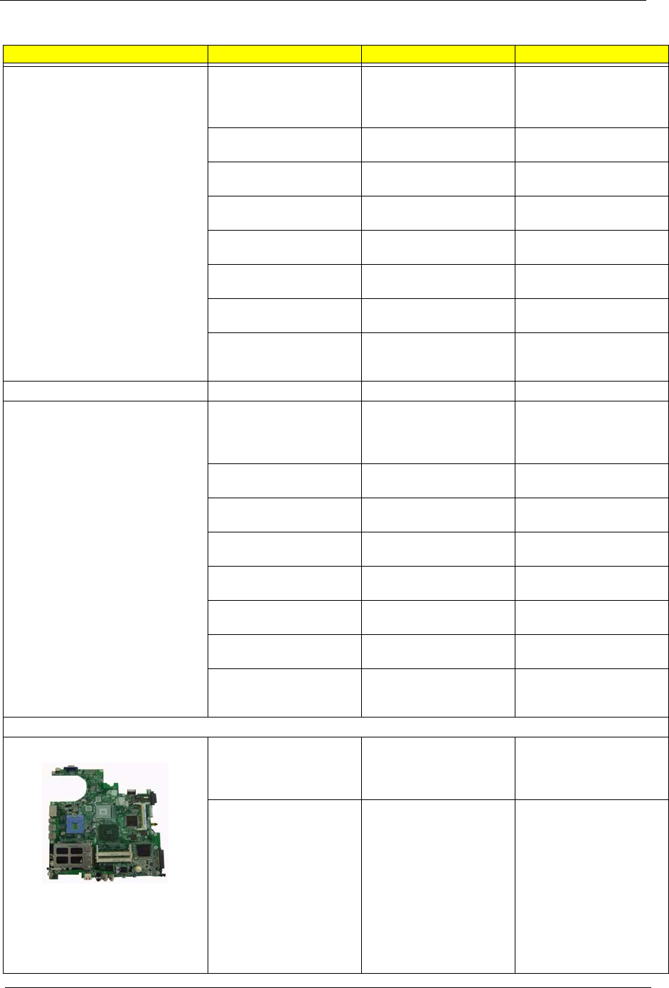
110 Chapter 6
LCD MODULE 15.4 IN.
WXGA SAMSUNG
LTN154X3-L01-LIGHT
GREEN SILVER
ZL1A 15.4" LCD WXGA (TM
QDI) ASSY S.P. NEW
COLOR
6M.T63V7.014
LCD 15.4 IN. WXGA
SAMSUNG LTN154X3-L01
ZL2 15.4" LCD (SAMSUNG)
PANEL ASSY S.P.
LK.15406.005
LCD INVERTER BOARD ZL1A LCD INVERTER
ASSY S.P.
19.T50V7.001
LCD CABLE - 15.4 IN.
WXGA
ZL1A 15.4" LCD WXGA
CABEL ASSY S.P.
50.T50V7.006
LCD BRACKET W/HINGE
15.4 IN. - L
ZL1A 15.4" LCD HINGE (L)
ASSY S.P.
33.T50V7.004
LCD BRACKET W/HINGE
15.4 IN. - R
ZL1A 15.4" LCD HINGE (R)
ASSY S.P.
33.T50V7.005
LCD BEZEL W/RUBBER
PAD 15.4 IN.
ZL1A 15.4" LCD BEZEL
ASSY S.P.
60.T50V7.006
LCD PANEL W/LOGO
ANTENNA 15.4 IN.- LIGHT
GREEN SILVER
ZL1A 15.4" LCD (TM)
COVER ASSY S.P. NEW
COLOR
60.T50V7.103
LCD MODULE 15.4 IN.
WXGA HITACHI
TX39D85VC1FAA-LIGHT
GREEN SILVER
ZL1A 15.4" LCD WXGA (TM
HITACHI) ASSY S.P. NEW
COLOR
6M.T63V7.015
LCD 15.4 IN. WXGA
HITACHI TX39D85VC1FAA
ZL2 15.4" LCD (HITACHI)
PANEL ASSY S.P.
LK.15404.003
LCD INVERTER BOARD ZL1A LCD INVERTER
ASSY S.P.
19.T50V7.001
LCD CABLE - 15.4 IN.
WXGA
ZL1A 15.4" LCD WXGA
CABEL ASSY S.P.
50.T50V7.006
LCD BRACKET W/HINGE
15.4 IN. - L
ZL1A 15.4" LCD HINGE (L)
ASSY S.P.
33.T50V7.004
LCD BRACKET W/HINGE
15.4 IN. - R
ZL1A 15.4" LCD HINGE (R)
ASSY S.P.
33.T50V7.005
LCD BEZEL W/RUBBER
PAD 15.4 IN.
ZL1A 15.4" LCD BEZEL
ASSY S.P.
60.T50V7.006
LCD PANEL W/LOGO
ANTENNA 15.4 IN.- LIGHT
GREEN SILVER
ZL1A 15.4" LCD (TM)
COVER ASSY S.P. NEW
COLOR
60.T50V7.103
MAINBOARD
MAINBOARD 915GM UMA
DOCKING 3 IN 1 W/
PCMCIA SLOT W/O CPU
MEMORY
ZL2 UMA M/B ASSY S.P. TBD
MAINBOARD 915PM M24P
64MB DOCKING 3 IN 1 W/
PCMCIA SLOT W/O CPU
MEMORY
ZL2 M24 M/B ASSY S.P. TBD
Illustraion Item Description Acer P/N
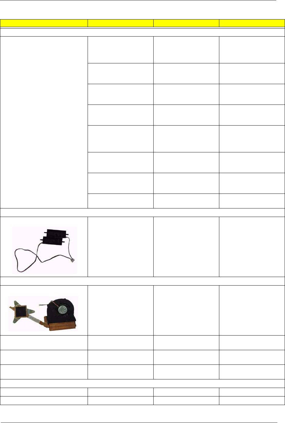
Chapter 6 111
MEMORY
MEMORY DDR333 256MB
INFINEON
HYS64D32020HDL-6-C
(.11u)
MEMORY DDR333 256MB
INFINEON
HYS64D32020HDL-6-C
(.11u)
KN.25602.012
256M Micron SO-DIMM
DDR333 256MB
MT4VDDT3264HG-335C2
256M Micron SO-DIMM
DDR333 256MB
MT4VDDT3264HG-335C2
KN.25604.016
MEMORY DDR333 256MB
SAMSUNG
M470L3224FT0-CB3
MEMORY DDR333 256MB
SAMSUNG
M470L3224FT0-CB3
KN.2560B.008
MEMORY DDR333 256MB
MICRON
MT8VDDT3264HDG-335C3
MEMORY DDR333 256MB
MICRON
MT8VDDT3264HDG-335C3
KN.25604.009
512MB Micron SO-DIMM
DDR333 512MB
MT8VDDT6464HDG-335C1
(.11u),
512MB Micron SO-DIMM
DDR333 512MB
MT8VDDT6464HDG-335C1
(.11u),
KN.51204.013
MEMORY DDR333 512MB
SAMSUNG
M470L6524BT0-CB3
MEMORY DDR333 512MB
SAMSUNG
M470L6524BT0-CB3
KN.5120B.006
SO-DIMM DDR333 512MB
UNIFOSA
U30512AAUIQ652AW20
SO-DIMM DDR333 512MB
UNIFOSA
U30512AAUIQ652AW20
KN.5120H.001
MEMORY DDR333 1GB
ELPIDA EBD11UD8ADDA
SO-DIMM DDR333 1GB
ELPIDA EBD11UD8ADDA
KN.1GB09.002
SPEAKER
SPEAKER SET ZL1A SPEAKER ASSY S.P. 23.T50V7.001
HEATSINK
THERMAL MODULE ZL2 CPU HEATSINK ASSY 60.T63V7.003
VGA HEATSINK FOR
DISCRETE W/PAD
ZL2 SINK VGA ASSY W/
NB
34.T63V7.001
VGA HEATSINK FOR
DISCRETE W/PAD
ZL2 SINK VGA ASSY W/
NB
34.T63V7.001
VGA HEATSINK FOR UMA
W/PAD
ZL2 SINK VGA ASSY W/O
NB
34.T63V7.002
MISCELLANEOUS
NAME PLATE- TM4600 ZL2 NAME PLATE S.P. 40.T63V7.001
RUBBER FOOT ZL1A RUBBER FOOT S.P. 47.T50V7.002
Illustraion Item Description Acer P/N

112 Chapter 6
LCD SCREW RUBBER PAD ZL1A RUBBER PAD-UP
S.P.
47.T50V7.003
LCD BEZEL RUBBER PAD ZL1A RUBBER PAD-2 S.P. 47.T50V7.004
WEIGHT SAVER ZL1 WEIGHT SAVER S.P. 60.T50V7.008
2nd HDD BASE W/
CONNECT
ZL1 2ND HDD BASE ASSY
S.P.
60.T50V7.009
2nd HDD COVER ZL1 2ND HDD COVER
ASSY S.P.
42.T50V7.015
2nd HDD BRACKET KIT ZL1 2ND BRACKET ASSY
S.P.
6K.T50V7.001
SCREW
SCREW M2.0X3.0-I-NI-
NYLOK
ET2S SCREW MM2.0X3.0
SPARE PART
86.A03V7.012
SCREW I2.5*3M-
BNIH(M2.5L3)
ZG1S I2.5*3M-
BNIH(M2.5L3) S/P
86.T25V7.012
SCREW M2.5*4L-BZN-
NYLOK
ET2S SCREW MM2.5X4.0
SPARE PART
86.A03V7.006
SCREW M2.0X5-I-NI-
NYLOK
ZI1S SCREW M2.0X5-I-NI-
NYLOK S/P
86.T23V7.006
SCREW MM25060IL69 DT1 SCREW MM25060IL69
SPARE PART
86.A08V7.004
SCREW M2.0*5-
I(NI)(NYLOK)
ZI1S SCREW M2.5X5.0-I-
NI-NYLOK S/P
86.T23V7.010
SCREW M2.0X2.5-I-NI-
NYLOK
ET2S SCREW MM2.0X2.5
SPARE PART
86.A03V7.007
SCREW I2*3M-NIHY
(M2L3)
ZG1S I2*3M-NIHY (M2L3)
S/P
86.T25V7.008
SCREW M1.7*3.0-I (BK) ZL1A SCREW (M1.7*3.1-I
(BK) S.P.
86.T50V7.001
SCREW I3*3.5M-
NIH(M3L3.5)
ET2S SCREW MM3.0X3.5
SPARE PART
86.A03V7.011
Illustraion Item Description Acer P/N
Appendix A A 113
TravelMate 4100 series
Aspire 1690 series
Model
Number CPU LCD Memory HDD Optical Mini PCI Battery VGA
Card
TM4101L PM730 15.0"
XGA
DDRII 60GB 8x DVD-
Dual
Intel220
0BG
Li-lon-
Crane
8cell
ATI
M24P/
64MB
TM4101WL PM730 15.4"
WXGA
DDRII 60GB 8x DVD-
Dual
Intel220
0BG
Li-lon-
Crane
8cell
ATI
M24/
64M
TM4102L PM740 15.0"
XGA
DDRII 60GB 24x
Combo
Intel220
0BG
Li-lon-
Crane
8cell
ATI
M24P/
64MB
TM4101L PM730 15.0"
XGA
DDRII 60GB 24x
Combo
Intel220
0BG
Li-lon-
Crane
8cell
ATI
M24P/
64MB
Model
Number CPU LCD Memory HDD Optical Card
Reader
Wireless
LAN Bluetooth Battery VGA
1691WL
Mi
PM730 15.4"
WXGA DDRII 60GB 8x DVD-
Dual (DL)
4 in 1-
Crane
Intel2200BG N/A Li-lon-
Crane
8cell
ATI
M24/
64M
1692WL
Mi
PM740 15.4"
WXGA DDRII 80GB 8x DVD-
Dual(DL)
4 in 1-
Crane
Intel2200BG AMOM+W
NCUSBT
Li-lon-
Crane
8cell
ATI
M24/
64M
Model Definition and Configuration
Appendix A

Appendix B 114
This computer’s compatibility is tested and verified by Acer’s internal testing department. All of its system
functions are tested under Windows XP Home environment.
Refer to the following lists for components, adapter cards, and peripherals which have passed these tests.
Regarding configuration, combination and test procedures, please refer to the Aspire 1690 and
Aspire 3510 Compatibility Test. Report released by the Acer Mobile System Testing
Department.
Test Compatible Components
Appendix B
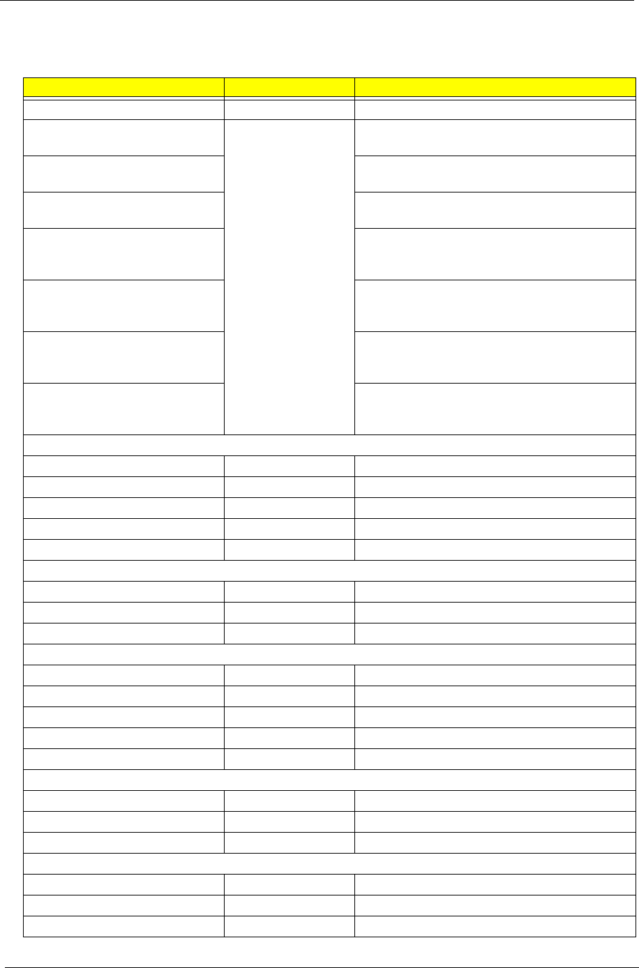
115 Appendix B
Microsoft Windows XP (Home) Environment Test
Component Manufacturer Specifications
CPU
Mobile, Intel Pentium M, 533MHz
FSB, Regular, uFCPGA, 2MB L2
Intel
Intel Pentium M 740 ( 1.73GHz/2M/533M FSB )
Mobile, Intel Pentium M, 533MHz
FSB, Regular, uFCPGA, 2MB L2
Intel Pentium M 730 ( 1.6GHz/2M/533M FSB )
Mobile, Intel Pentium M, 400MHz
FSB, Regular, uFCPGA, 2MB L2
Intel Pentium M 715A ( 1.5GHz/2M/400M FSB )
Mobile, Intel Celeron M, 400MHz
FSB, Regular, uFCPGA, 512KB
L2
Intel Celeron M 340 ( 1.5GHz/512K/400M FSB )
Mobile, Intel Celeron M, 400MHz
FSB, Regular, uFCPGA, 512KB
L2
Intel Celeron M 350 ( 1.3GHz/1M/400M FSB )
Mobile, Intel Celeron M, 400MHz
FSB, Regular, uFCPGA, 512KB
L2
Intel Celeron M 360 ( 1.4GHz/1M/400M FSB )
Mobile, Intel Celeron M, 400MHz
FSB, Regular, uFCPGA, 512KB
L2
Intel Celeron M 370 ( 1.5GHz/1M/400M FSB )
LCD(15" XGA LCD )
SPWG-B, 170nits typ, XGA AU B150XG02 V.2
SPWG-B, 160nits typ, XGA LG LP150X08-A3
SPWG-B, XGA Samsung LTN150XB-L03-C00
SPWG-B, XGA Hitachi TX38D81VC1CAB Rev.C
SPWG-B, XGA CMO N150X3-L07
LCD (15" SXGA+ LCD)
SPWG-B, 200nits typ,SXGA+ AU B150PG03 (Novatec)
SPWG-B, SXGA+ IDT N150P2-L04
SPWG-B, SXGA+ Samsung LTN150P4-L03
LCD (15.4" WXGA LCD)
SPWG-B, WXGA CMO N154I1-L09
SPWG-B, 170 nits typ, WXGA LPL LP154W01-A5
SPWG-B, WXGA Hitachi TX39D85VC1FAA
SPWG-B, 200 nits typ, WXGA Samsung LTN154X3-L01
SPWG-B, 185nits typ, WXGA QDI QDI15TL02-01
LCD (14" XGA LCD)
SPWG-B, XGA, 14" AU B141XG10
SPWG-B, XGA, 14" Toppoly TD141TGCD2
SPWG-B, XGA, 14" CMO N141XB-L01
LCD (15.4" WSXGA+ LCD)
SPWG-B, 185nits, WSXGA+ LG LP154W02-B1K1
SPWG-B, 185nits, WSXGA+ SAMSUNG LTN154P1-L02
SPWG-B, 185nits, WSXGA+ HITACHI TX39D99VC1FAA
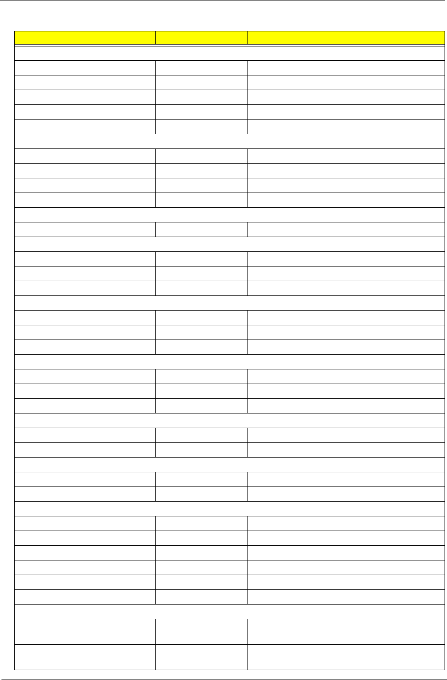
Appendix B 116
Memory ( 256MB)
1.25" module, DDR-333 Nanya ( .11u)
1.25" module, DDR-333 Infineon HYS64D32020HDL-6-C 32x64 (.11u/G)
1.25" module, DDR-333 Micron MT4VDDT3264HG-335C2 (0.11u/512Mb)
1.25" module, DDR-333 Micron MT8VDDT3264HDG-355C3
1.25" module, DDR-333 Samsung M470L3224FT0-CB3 (.13u)
Memory 512MB
1.25" module, DDR-333 Infineon TBD
1.25" module, DDR-333 Micron MT8VDDT6464HDG-335C1
1.25" module, DDR-333 Samsung M470L6524BT0-CB300
1.25" module, DDR-333 Unifosa U30512AAUIQ652AW20
Memory 1GB
1.25" module, DDR-333 Elpida EBD11UD8ADDA
HDD (40GB)
2.5" ,4200rpm HGST Moraga+ HTS424040M9AT00 13G1132
2.5" ,4200rpm TOSHIBA Pluto MK4025GAS ,KA100A
2.5" ,4200rpm Seagate N1 ST94019A, 2MB
HDD 60GB
2.5" ,4200rpm HGST Moraga IC25N060ATMR04-0 08K0634
2.5" ,4200rpm TOSHIBA Pluto MK6025GAS
2.5" ,4200rpm Seagate N2-50 ST960821A
HDD 80GB
2.5" ,4200rpm HGST Moraga IC25N080ATMR04-0 08K635
2.5" ,4200rpm TOSHIBA Pluto MK8025GAS, 8MB
2.5" ,4200rpm Seagate N2-50 ST9808210A
HDD 60GB
2.5" ,5400rpm HGST Moraga+ HTS541060G9AT00
2.5" ,5400rpm TOSHIBA Proteus MK6026GAX, 16MB
HDD 80GB
2.5" , 5400rpm HGST Moraga+ HTS541080G9AT00
2.5" , 5400rpm TOSHIBA Proteus MK8026GAX
Communication
LAN Broadcom,GbE
LAN Broadcom,10/100
Modem SW Modem, V.92, MDC
Wireless 802.11 a/b/g Intel
Wireless 802.11 b+g Intel
Wireless 802.11 b+g Intel T60N874.00
Main Chip & Others
Battery Li-Ion Sanyo Sanyo Li-Ion 8 Cell 4UR18650F-2-QC140
ZL1,4S2P,4.4A / AHA842223I4
Battery Li-Ion Panasonic Panasonic Li-Ion 8 Cell CGR-B/
8B5AE,ZL1,4S2P,14.8V,4.4A / AHA84222050
Component Manufacturer Specifications

117 Appendix B
Battery Li-Ion Simplo Simplo Li-Ion 8 Cell 916-3020 4S2P,4.4A /
AHA842221I0
Battery Li-Ion Sanyo Sanyo Li-Ion 4 Cell 4UR18650F-QC141
ZL1,4S1P,2.2A / AHA44122A01
Battery Li-Ion Panasonic Panasonic Li-Ion 4 Cell CGR-B/
423AE,ZL1,4S1P,14.8V,2.2A / AHA44122712
Battery Li-Ion Simplo Simplo Li-Ion 4 Cell 916-2990 4S1P,2.2A /
AHA44122909
2nd battery Sanyo Sanyo 3UF103450P-2-QC148 ZL1,3S2P,3.8A
6cell 2nd Bat / AHA63217219
Component Manufacturer Specifications

Appendix C 118
This section describes online technical support services available to help you repair your Acer Systems.
If you are a distributor, dealer, ASP or TPM, please refer your technical queries to your local Acer branch
office. Acer Branch Offices and Regional Business Units may access our website. However some information
sources will require a user i.d. and password. These can be obtained directly from Acer CSD Taiwan.
Acer's Website offers you convenient and valuable support resources whenever you need them.
In the Technical Information section you can download information on all of Acer's Notebook, Desktop and
Server models including:
TService guides for all models
TUser's manuals
TTraining materials
TBios updates
TSoftware utilities
TSpare parts lists
TTABs (Technical Announcement Bulletin)
For these purposes, we have included an Acrobat File to facilitate the problem-free downloading of our
technical material.
Also contained on this website are:
TDetailed information on Acer's International Traveler's Warranty (ITW)
TAn overview of all the support services we offer, accompanied by a list of telephone, fax and email
contacts for all your technical queries.
We are always looking for ways to optimize and improve our services, so if you have any suggestions or
comments, please do not hesitate to communicate these to us.
Online Support Information
Appendix C
