Acer H243H User Manual To The 8cd63719 7052 48c8 A3b1 495ccb44e580
User Manual: Acer H243H to the manual
Open the PDF directly: View PDF ![]() .
.
Page Count: 55

Acer Acer –LCD-H243H
- 0 -
Service Manual
LCD Monitor Acer H243H
1
1
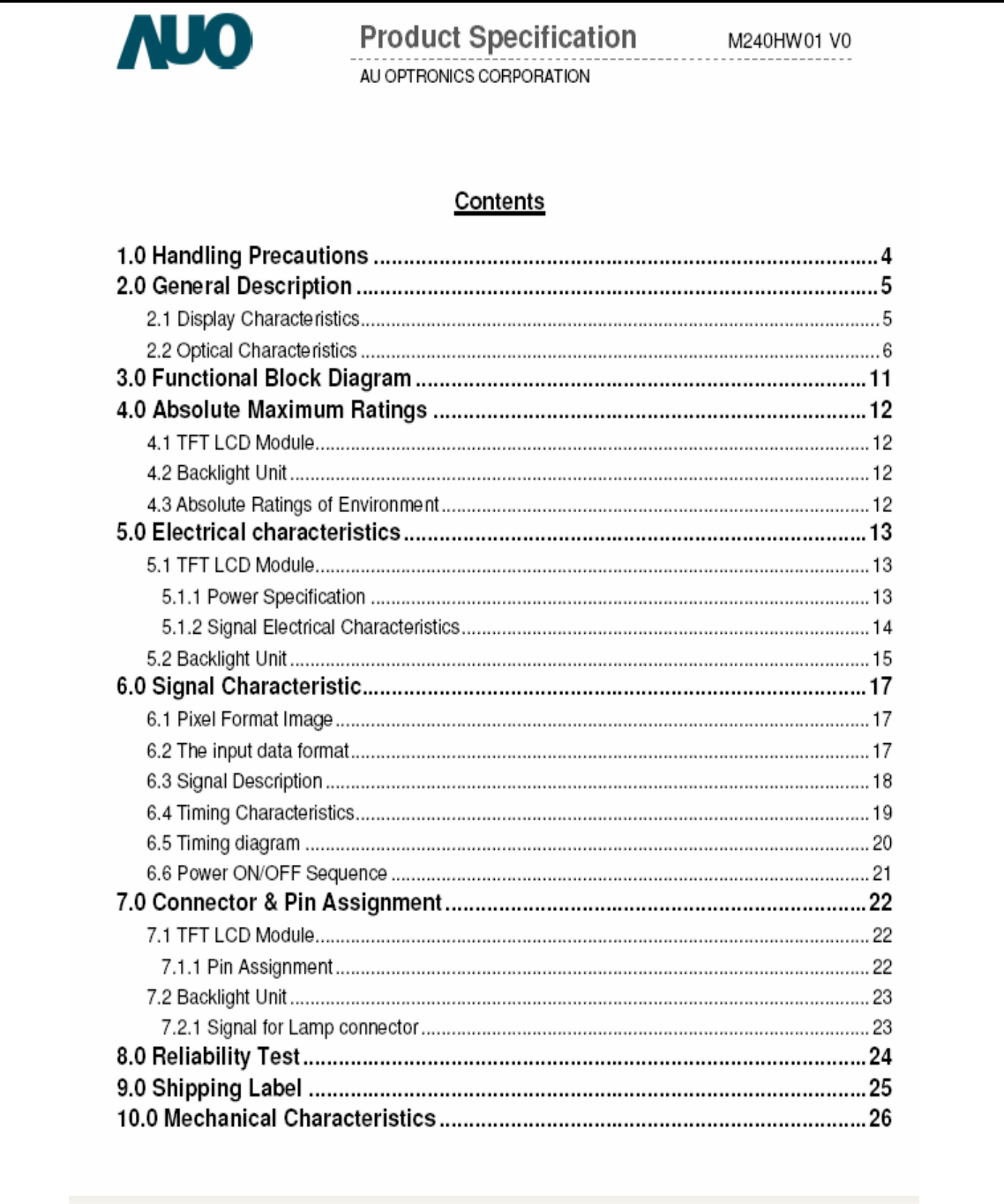
Table of Contents
Important Safety Notice .........................................................................................02
01 Product Specification ..........................................................................................03
02 Flat Panel Specification .......................................................................................15
03 Exploded Diagram ..............................................................................................36
04 Troubleshooting ....................................................................................................37
05 Spare Parts List ...................................................................................................42
06 Schematics and Layouts.......................................................................................43
07 Assembly and Disassembly ................................................................................46
Appendix : User’s manual
Copyright
Copyright 2006 InnoLux Tech. Corp. Ltd
All Rights Reserved
This manual may not, in whole or in part, be copied, Photocopied, reproduced, translated, or converted to any
electronic or machine readable form without prior written permission of InnoLux Tech. Corp. Ltd.
Acer H243H Service Manual

Acer Acer –LCD-H243H
2
Important Safety Notice
1. Safety precautions
This monitor is manufactured and tested on a ground principle that a user’s safety comes first.
However, improper used or installation may cause damage to the monitor as well as to the user.
Warning:
z This monitor should be operated only at the correct power sources indicated on the label on the
rear of the monitor. If you’re unsure of the power supply in you residence, consult your local dealer
or Power Company.
z Do not try to repair the monitor by yourself, as it contains no user-serviceable parts. This monitor
should only be repaired by a qualified technician.
z Do not remove the monitor cabinet. There are high-voltage parts inside that may cause electric
shock to human bodies.
z Stop using the monitor if the cabinet is damaged. Have it checked by a service technician.
z Put your monitor only in a lean, cool, dry environment. If it gets wet, unplug the power cable
immediately and consult your closed dealer.
z Always unplug the monitor before cleaning it. Clean the cabinet with a clean, dry cloth. Apply
non-ammonia based cleaner onto the cloth, not directly onto the class screen.
z Do not place heavy objects on the monitor or power cord.
2. Product safety notice
Many electrical and mechanical parts in this chassis have special safety visual inspections and the
protection afforded by them cannot necessarily be obtained by using replacement components rated
for higher voltage, wattage, etc. Before replacing any of these components read the parts list in this
manual carefully. The use of substitute replacement parts, which do not have the same safety
characteristics as specified in the parts list, may create shock, fire, or other hazards.
3. Service notes
z When replacing parts or circuit boards, clamp the lead wires around terminals before soldering.
z Keep wires away from high voltage, high temperature components and sharp edges.
z Keep wires in their original position so as to reduce interference.
z Adjustment of this product please refers to the user’ manual.

Acer Acer –LCD-H243H
3
01 Product Specification
1. General:
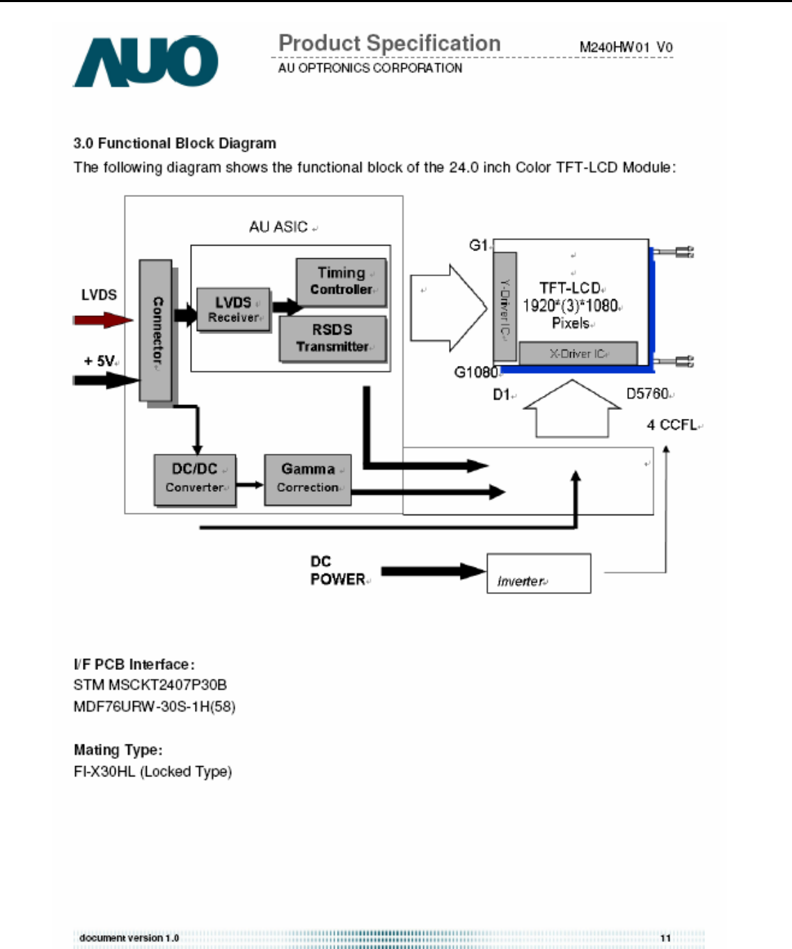
H243H is designed with LVDS interface and VGA/DVI-D/HDMI input, it featured with embedded universal AC power supplies and
audio input. It’s a green product and meets all ROHS standard. The power button and display control buttons are on the front of the
monitor. The monitors shall automatically to display lower resolution video modes into1920x1080full screen display. The image can
be adjusted through OSD control. It support HDCP and color management function.
1.1 Main Features
Maximum resolution : 1920(x3) x 1080 @ 60Hz
Back light system : 4 CCFL (top & bottom edge side)
Pixel pitch : 276.75 um (H) x 276.75 um (V)
Display area : 531.36mm (H) x 298.89mm (V)
Brightness : 300cd/m² (TYP.)
Contrast ratio : 1000׃1 (TYP.) (1)
DCR : 40000:1 (Max)
Response time (Tr+Tf) : 5ms (TYP. ON/OFF) (2)
2ms (Gray to Gray)
Viewing angle : 170° (H)/ 160°(V), (TYP.) (3)
Input interface : Analog (D-sub 15 pin)
Digital Option (DVI-D 24 pin & HDMI 19Pin)
Power management : Compatible with VESA DPMS
Plug & Play : VESA DDCCI
OSD language : English, French, Spanish, Italian, Deutsch,
Simplified Chinese, Traditional Chinese, Japanese
(Dutch, Finnish, Russian depend on sale region)
Universal AC power supply
Note (1)(2)(3): This item spec depend on the LCD panel.
1.2 Accessories
AC Power Cord : 1.8 m. (Black. Cord type depend on sale region)
VGA cable : 1.8 m. (15 pin D-SUB, black cable with blue male connector)
User manual : English (640Mb CD)
Warranty card :
DVI cable (option) : 1.8 m. (18+1 pin, black cable with white connector)
HDMI cable (option) : 1.8 m. (19 pin, black cable with white connector)
2. Operation Specifications
The unit should suffer no visible cosmetic damage and should operate with no degradation in display quality during exposure to
the operating conditions and after exposure to the non-operating conditions, in any sequence.
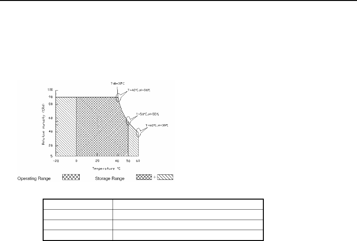
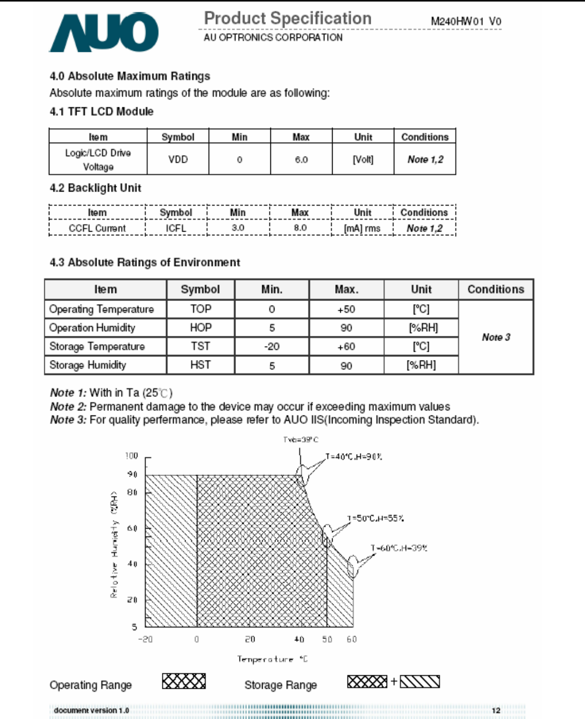
2.1 Environmental conditions
2.1.1 Operating:
Temperature range : 0°C to 50°C
Relative humidity : 5% to 90%
2.1.2 Storage note 1:
Acer Acer –LCD-H243H
4
Temperature range : -20°C to 60°C
Humidity range : 5% to 90%
2.1.3 Altitude
note 2
Operating 10000 ft (Ta=50, t=24h)
Storage 30000 ft (Ta=30, t=24h )
Note 1: Temperature and relative humidity range must be in the area shown as the following figure due to panel
limited
Note 2: Altitude spec must not over panel spec.
2.2 Safety, EMC, Ergonomics and Compatibility Requirements
Safety & EMC MET, CB, Bauart, CCC, FCC, CE, VCCI-B
Ergonomics MPRII ISO13406-2
Compatibility Windows 95/98/Me/2000, Windows XP, Window Vista
Power Management Energy Star
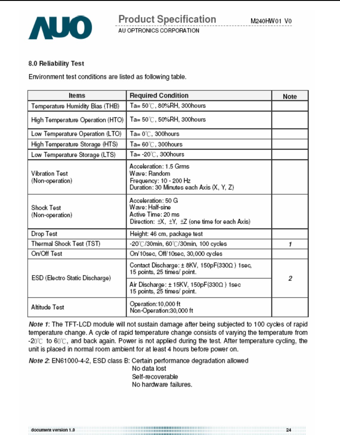
2.3 Electrostatic Discharge Requirements
The subject unit must withstand ±8KV for contact discharge and ±15KV for air discharge of Electrostatic Discharge
and meet the standard of IEC61000-4-2(EN55024). (without discharge on VGA/DVI pin)
2.4 Reliability
The MTBF of this product shall be greater than 25,000 hours excluding the LCD panel. The LCD panel life which is
defined as the time period for the maximum luminance to reduce to 50% of the initial value is 40,000 hours minimum at
the condition of displaying an all WHITE field at mid Brightness and Contrast settings.
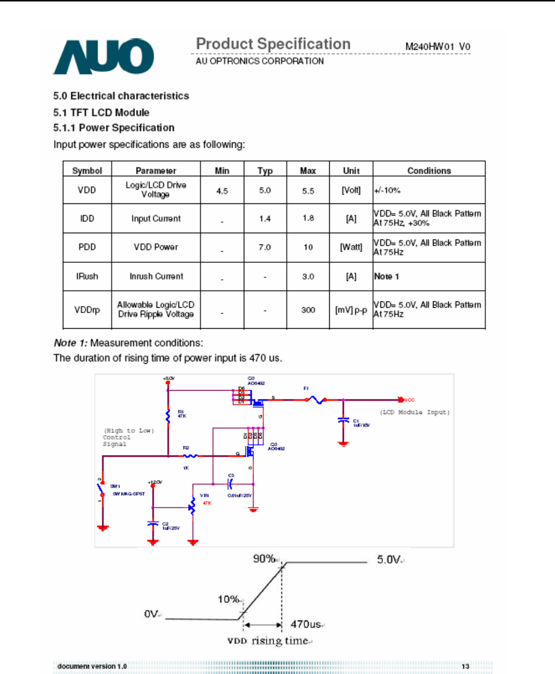
3. Electrical and Optical Characteristics and Performance
3.1 Main Power Supply
3.1.1AC Input Voltage Range
It is a universal type and the input voltage range is from 100 ~ 240Vrms
3.1.2 AC Input Current
1.5A (max) at 100VAC input
0.8A (max) at 240VAC input
AC Frequency Range
The frequency range is from 50Hz to 60Hz
Inrush Current
a. 40A max at cold-start, 25°C, DC output full-loading and 100Vac input
b. 60A max at cold-start, 25°C, DC output full-loading and 240Vac input
Regulator Efficiency
Acer Acer –LCD-H243H
5
≥75%
(DC output full loading and nominal AC input voltage range)
Ripple and Noise
Total composite ripple and noise less than 800mV for +25V output, and less than 150mV for +5V output, and 50mV for
+3.3V output tested by DC loading side parallel with a 47uF/EC and 0.1uF/Ceramic. Capacitors and measured band-width
with DC-20MHz
DC Output Voltage and Current
3.1 Brightness output
The test to verify specifications in this section shall be performed under the following standard conditions unless
otherwise noted.
Temperature : 25 ± 5°C
Test pattern : white
Video Resolution : 1920 x 1080
Video input level : 700 mV ± 2%
Warm-up time : 30 minutes
Set brightness control and also contrast control at maximum, to measure the screen center, the light output shall BL ≥ 240
cd/m2 (as panel spec).
3.2 White balance
The test standard conditions refer to Sec 3.1.( Brightness and contrast are under default value )
Chromaticity Coordinate
Mode x y
Cool 9300K 0.283 ± 0.030 0.297 ± 0.030
Warm 6500K 0.313 ± 0.030 0.329 ± 0.030
User Panel While x Panel While y
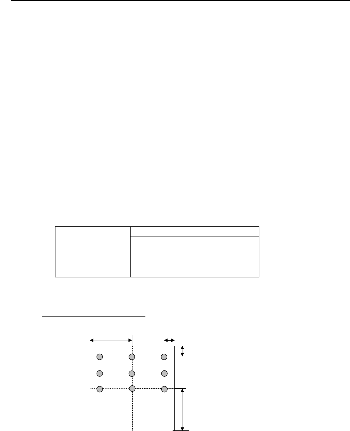
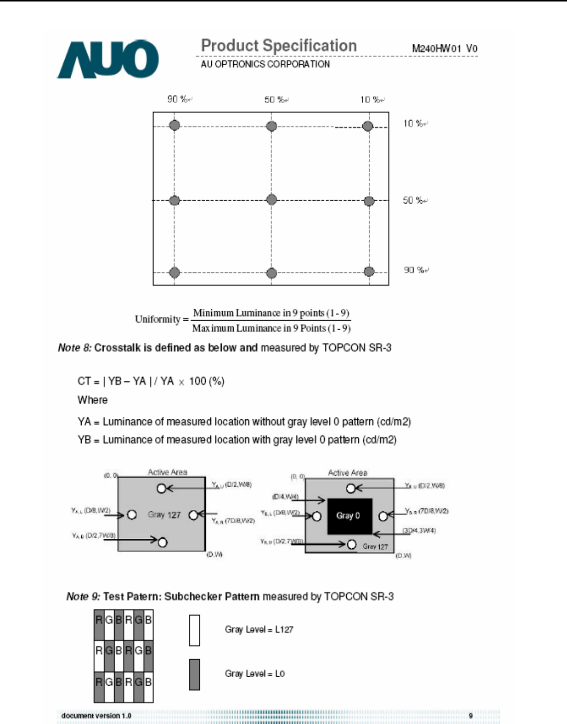
3.3 Brightness uniformity
The test standard conditions refer to Sec 3.1.
%
≥75
)(backlight points nine of luminance Max.
)(backlight points nine of luminance Min.
L/2 L/10
W/10
W/2
1 2
5
7 9
3
4 6
8
Acer Acer –LCD-H243H
6
4. Input / Output Signal Specifications
4.1 Video signals
Analog RGB signal: 0.7Vp-p (Input impedance = 75 Ohm)
Sync: TTL level (Input impedance ≧1k Ohm)
Positive and negative sync of Separate Horizontal/Vertical Sync
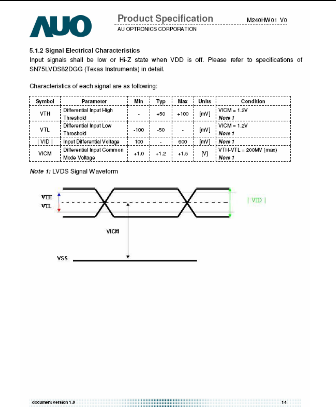
Digital : TMDS Signal: (min) ±200mVpp@24Bit
4.2 Signal Timing
Through D-SUB/DVI connectors, this unit can support FH= 31~80 KHz, Fv=55~76Hz, with maximum
pixel clock 165MHz input signal and WSXGA+ output. Modes details as below:
VESA MODES
Mode Resolution Total H Frequency V Frequency Pixel Clock
(MHz)
640x480 800 x 525 31.469 59.941 25.175
640x480 832 x 520 37.861 72.809 31.500
VGA
640x480 840 x 500 37.500 75.000 31.500
800x600 1024 x 625 35.156 56.250 36.000
800x600 1056 x 628 37.879 60.317 40.000
800x600 1040 x 666 48.077 72.188 50.000
SVGA
800x600 1056x625 46.875 75.000 49.500
1024x768 1344x806 48.363 60.004 65.000
1024x768 1328x806 56.476 70.069 75.000
XGA
1024x768 1312x800 60.023 75.029 78.750
1152x864 1600x900 67.5 75 108
VESA 1280x960 1800x1000 60 60 108
1280x1024 1688x1066 63.981 60.020 108.000
SXGA 1280x1024 1688x1066 79.976 75.025 135.000
VESA 1280x720 1650x750 44.955 59.940 74.176
1280x800 1680x831 49.702 59.810 83.500
WXGA 1360x768 1792x795 47.712 60.015 85.500
1440x900 1904x931 55.935 59.887 106.500
WXGA+ 1440x900 1936x942 70.635 75.000 136.750
SXGA+ 1400x1050 1864x1089 65.317 59.978 121.75
WSXGA+ 1680x1050 2240*1089 65.290 59.954 146.250
1600x1200 2160x1250 75.000 60.000 162.000
UXGA 1920x1080-R 2080x1111 66.587 59.934 138.50
IBM MODES
EGA 720x400 900x449 31.469 70.087 28.322
MAC MODES
VGA 640x480 864x525 35 66.66 30.24
SVGA 832x624 1152x667 49.722 74.55 57.28
SXGA 1152x870 1568x909 68.700 75.000 84.520
Note: 1. Non-interlace signals only (An interlace signal cannot be display)
2. Please refer to F/W specification for more detail
3. Each frequency of Power Macintosh and Sun Ultra is a reference value
4.3 Timing requirements
The LCD monitor must be capable of displaying standard resolutions within the vertical frequency range of 55 ~ 76 Hz and
the horizontal scan range of 31 ~ 80 KHz with maximum pixel clock of 190MHz.
Acer Acer –LCD-H243H
7
Vertical / Horizontal Sync polarity: positive or negative.
If input signal is out of range of horizontal 31~80 KHz or vertical 55-76Hz, or pixel clock large than 165MHz, message
“Input Not Supported” is shown on screen.
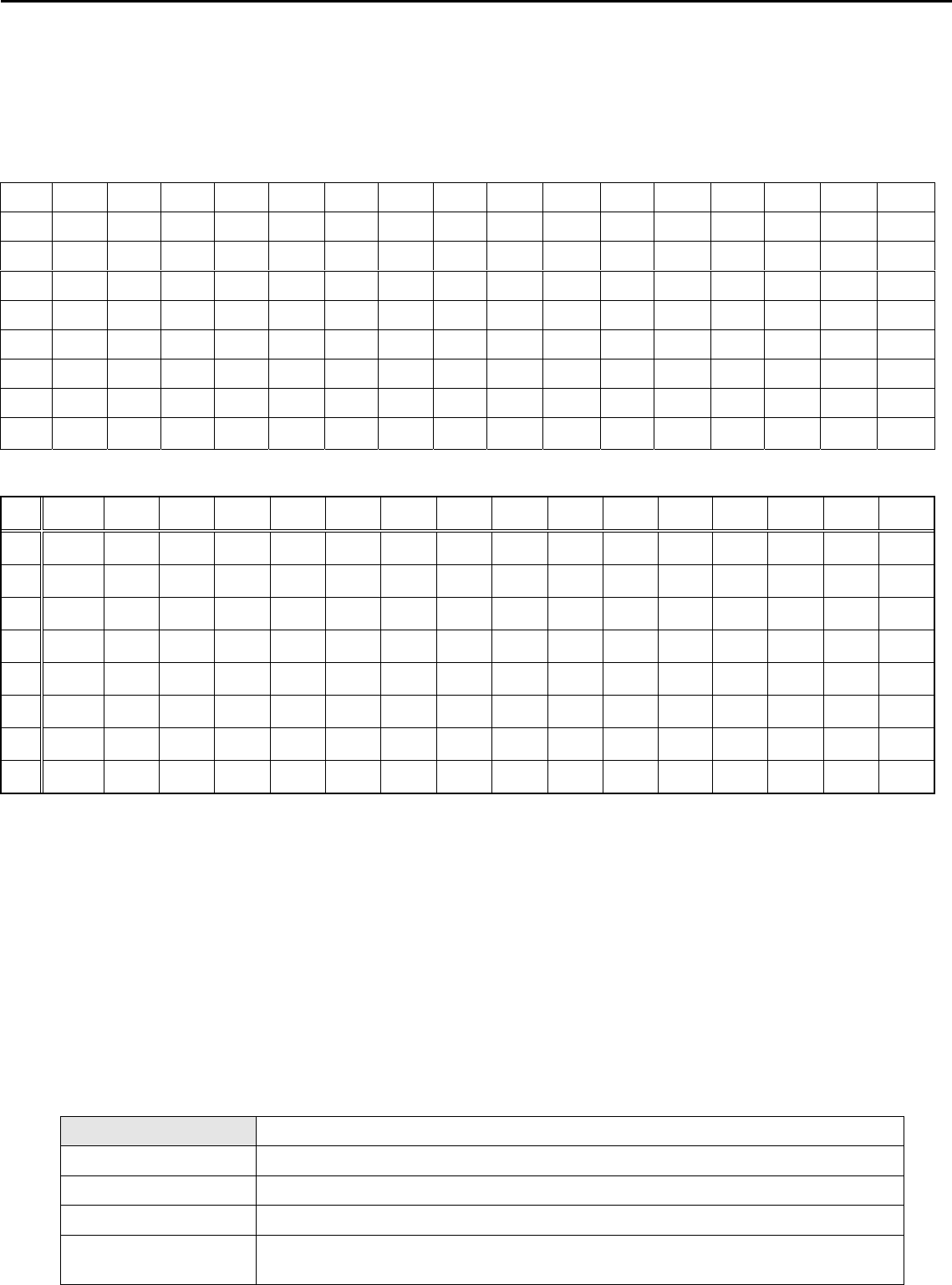
4.1 DDC data
H243H Analog
H243H DVI
0 1 2 3 4 5 6 7 8 9 A B C D E F
0 00 FF FF FF FF FF FF 00 04 72 74 00 01 01 01 01
1 00 00 01 03 80 35 1D 78 EA 60 85 A6 56 4A 9C 25
2 12 50 54 AF CF 00 81 80 71 4F 95 00 95 0F A9 40
3 B3 00 01 01 01 01 1A 36 80 A0 70 38 1F 40 30 20
4 35 00 13 2A 21 00 00 1A 00 00 00 FC 00 48 32 34
5 33 48 0A 20 20 20 20 20 20 20 00 00 00 FD 00 38
6 4C 1F 53 12 00 0A 20 20 20 20 20 20 00 00 00 FF
7 00 30 30 30 30 30 30 30 30 30 30 30 30 30 00 CS
5. Function Specifications
All the tests to verify specifications in this section shall be performed under the following standard conditions unless otherwise
noted. The standard conditions are:
Temperature : 25 ± 5°C
Warm-up time : 30 minutes minimum
Checking display modes : All the specified modes
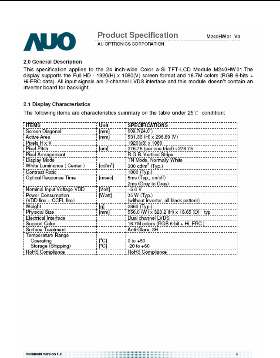
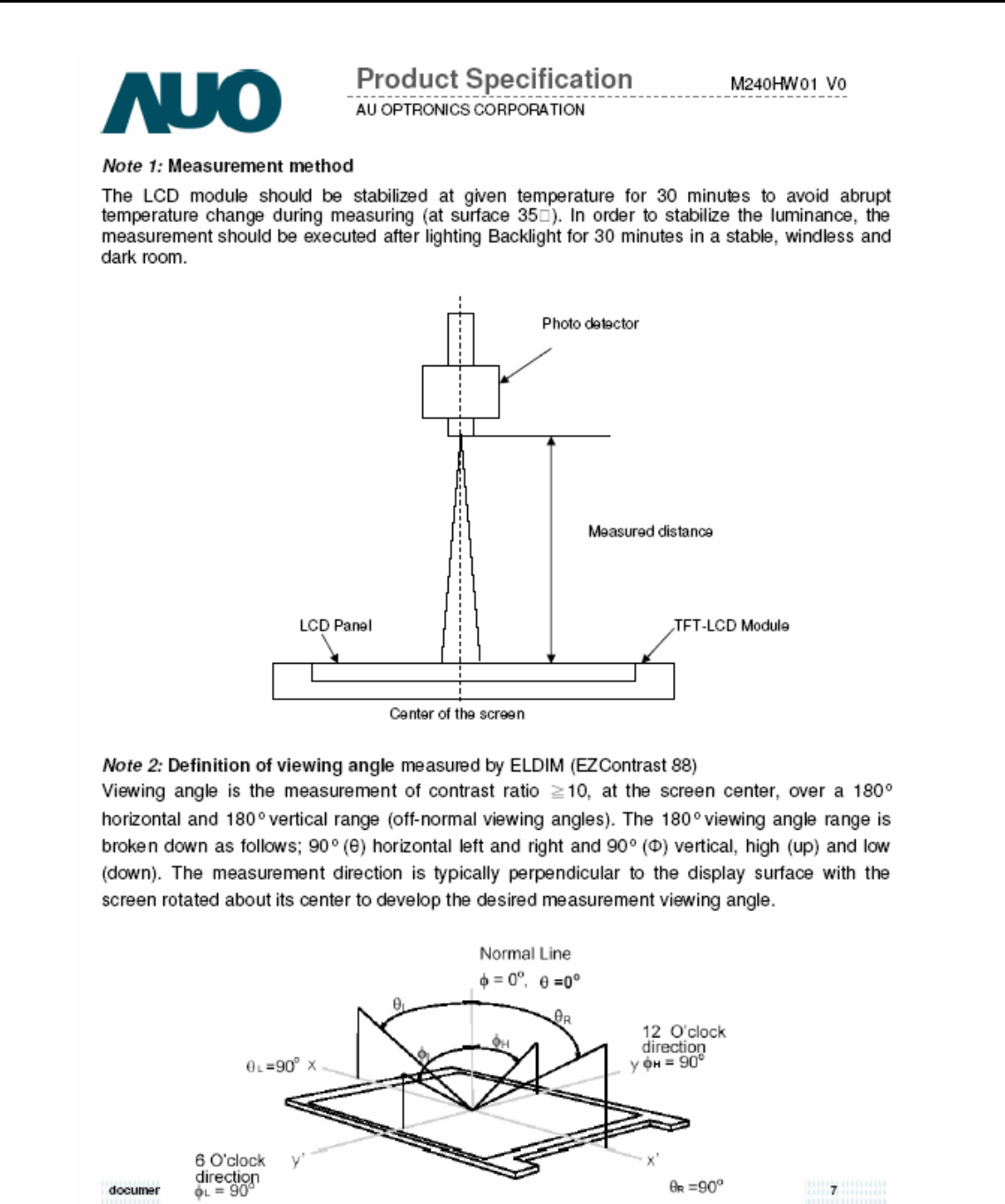
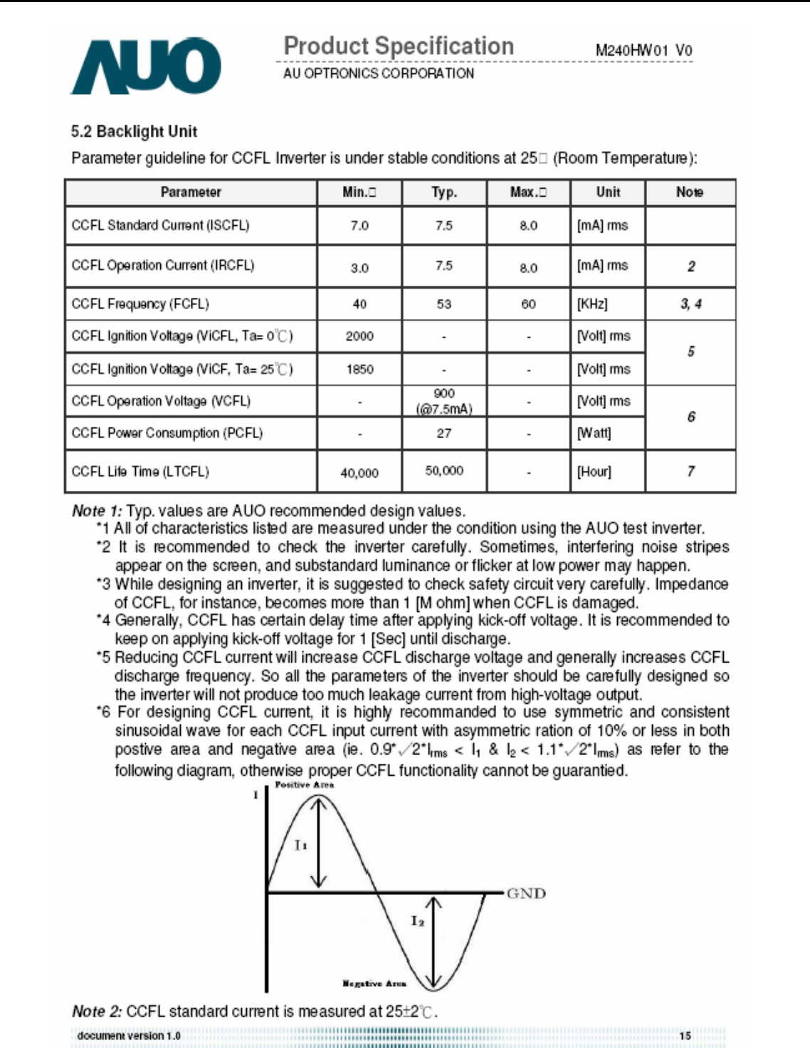
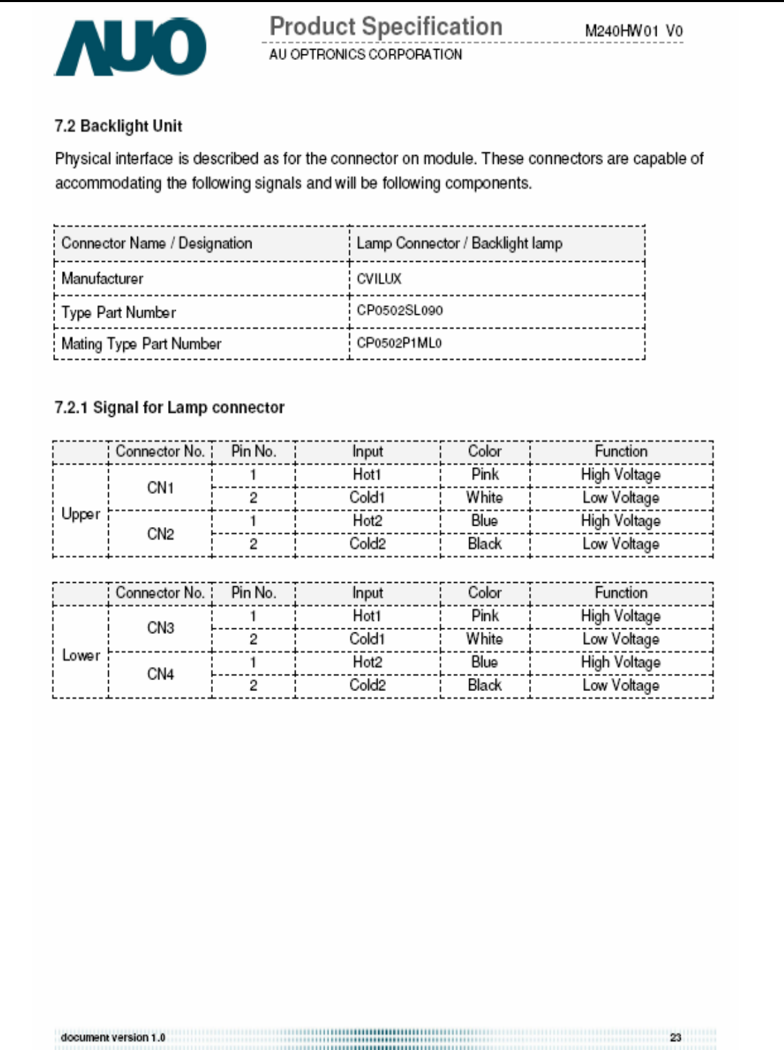
5.1 Panel general specifications
A General specifications
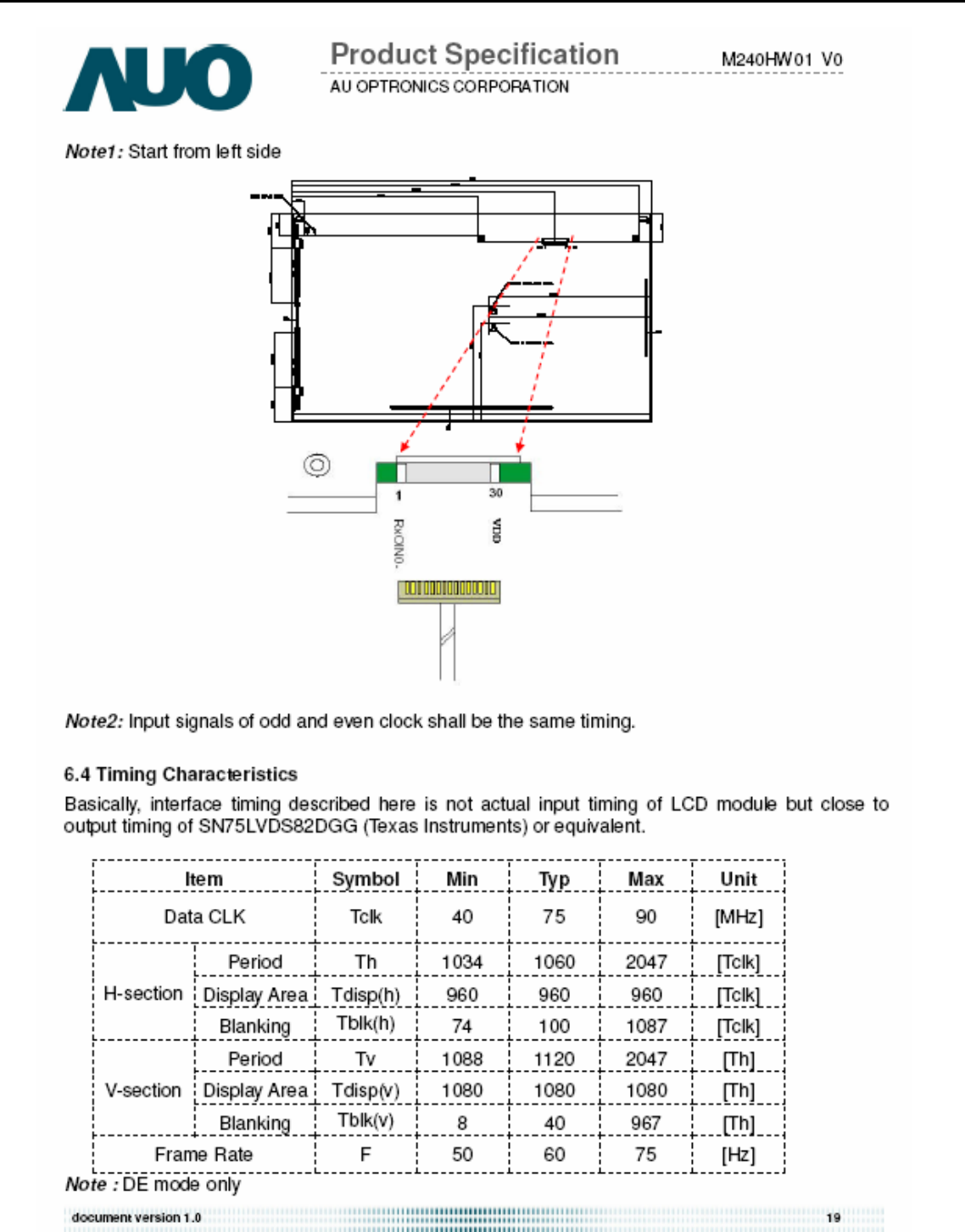
Supplier AUO
Model name M240HW01-V0
Display Area 531.36 × 298.89
Pixel Pitch 276.75(Per one triad) × 276.75
Display Colors: 16.7M colors (RGB 6-bit + Hi_FRC)
0 1 2 3 4 5 6 7 8 9 A B C D E F
0 00 FF FF FF FF FF FF 00 04 72 74 00 01 01 01 01
1 00 00 01 03 68 35 1D 78 EA 60 85 A6 56 4A 9C 25
2 12 50 54 AF CF 00 81 80 71 4F 95 00 95 0F A9 40
3 B3 00 01 01 01 01 1A 36 80 A0 70 38 1F 40 30 20
4 35 00 13 2A 21 00 00 1A 00 00 00 FC 00 48 32 34
5 33 48 0A 20 20 20 20 20 20 20 00 00 00 FD 00 38
6 4C 1F 53 12 00 0A 20 20 20 20 20 20 00 00 00 FF
7 00 30 30 30 30 30 30 30 30 30 30 30 30 30 00 CS
Acer Acer –LCD-H243H
8
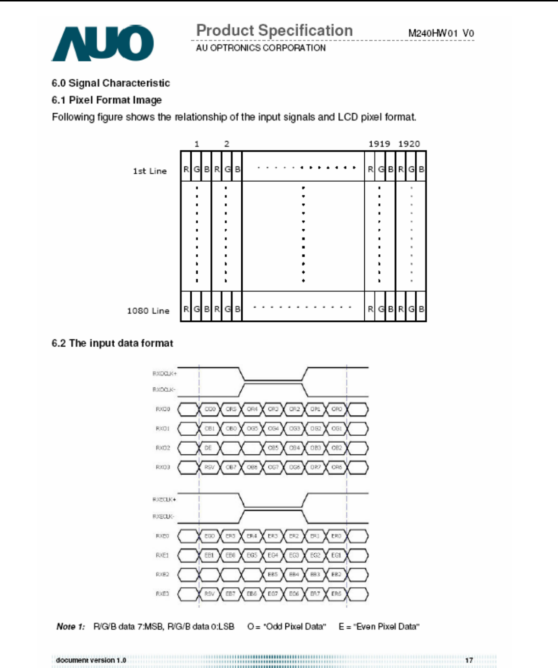
Number of Pixel 1920 × 1080
Pixel Arrangement R.G.B. Vertical Stripe
Brightness 300 cd/m2 (TYP.)
Contrast Ratio 1000 (TYP.)
Viewing Angle 170(Horizontal) / 160(Vertical)
Display Mode Normally White
Frame rate 75
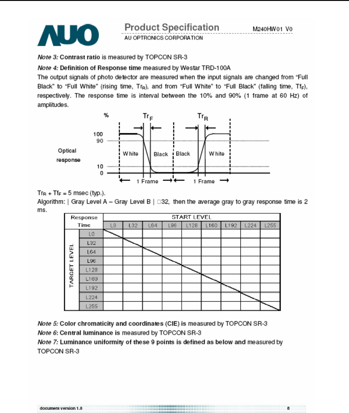
Response Time 5ms (TYP. ON/OFF) / 2ms (Gray to Gray)
Surface Treatment Anti-Glare, 3H
Lamp 4
Outline Dimension 556.0(W) ×323.2(H) ×16.65(D) (TYP.)
5.2 Keypad Function
5.2.1 Control buttons on the front bezel
C
ONTROL KEY KEYS FUNCTION
[POWER] Power on or power off the monitor
[►], [◄]
A. When “Main OSD” displays, press these keys to change the contents of an adjustment
item, or change an adjustment value
B. When “Main OSD” un-displays, press [►] to show “Audio” OSD and increase the
volume, press [◄] to show “Audio” OSD and decrease the volume .
[MENU]
A. When “Main OSD” un-displays, press [MENU] to enter OSD interface.
B. When “Main OSD” displays, press [MENU] to perform function of menu icon that is
highlight or enter next level menu.
[AUTO]
A. When “Main OSD” un-displays, press [AUTO] to perform auto-adjustment
B. When “Main OSD” displays, press [AUTO] to return to previous level menu
C. When “Empowering Technology OSD” displays, press [AUTO] to exit the OSD
[e Color ]
A. When “Main OSD” un-displays, press [e Color] to show “Empowering Technology
OSD”.
B. When “Main OSD” displays, press [e Color] to exit the OSD, and to show “Empowering
Technology OSD”
[Input select]
A. Press ”input key” one time to search (a port with signal in order)
B. Show “source icon” at the same time, as searching that port
C. Go into next port automatically, if search the port without signal
D. Display it, if search the port with signal
5.3 Hot Key Operation
HOT KEY OPERATION
FUNCTION
e Color AUTO MENU ◄ ► POWER DESCRIPTION
Acer Acer –LCD-H243H
9
FACTORY
MODE ● ON
Press [e], and then press
[POWER] for DC power on.
OSD menu will be shown with
“F” on the left top. Select “F” for
entering factory mode.
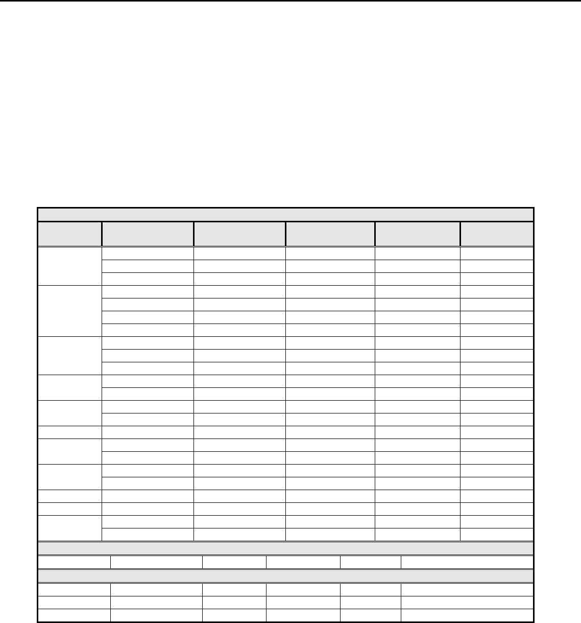
5.4 OSD Structure
The On-Screen Display (OSD) shall be an easy to use icon based menu through keypad OSD buttons or remote control
unit. The unit shall leave the factory with all OSD controls set to their default values.
First Second Third Fourth Control
Range Default Value
User
Text
Standard
Graphics
Acer e color
Management empowering Technology
Movie
--- Standard
User mode 77
Text mode 44
Standard mode 77
Graphics mode 97
Brightness --- --- 0~100
Movie mode 77
User mode 50
Text mode 50
Standard mode 50
Graphics mode 60
Contrast --- --- 0~100
Movie mode 56
H. Position 0~100 50
V. Position 0~100 50
Focus 0~100 ---
Clock
--- ---
0~100 50 (1)
Warm --- --- ---
Cool --- --- ---
Red 0~100 80
Green 0~100 80
Color Temp
User
Blue 0~100 80
Picture
Auto Configure --- --- --- ---
H. Position --- --- 0~100 Depending on the keypad
position
V. Position --- --- 0~100 3
OSD
OSD Timeout --- --- 10~120 10
Full --- ---
Wide Mode Aspect --- --- Full
Setting
DDC/CI ON --- --- ON
Acer Acer –LCD-H243H
10
OFF
ON
ACM OFF --- --- OFF
VGA --- ---
DVI --- ---
Input
HDMI --- ---
---
EMEA NO-EMEA
--- ---
English English --- ---
Russian 繁體中文 --- ---
Deutsch Deutsch --- ---
Français Français --- ---
Español Español --- ---
Italiano Italiano --- ---
Dutch 简体中文 --- ---
Language
Finnish 日本語 --- ---
English
Reset --- --- --- ---
Resolution --- --- ---
H. Freq --- --- ---
V. Freq --- --- ---
Input Type --- --- ---
Info
S/N --- --- ---
(2)
Notes: (1) Clock default 50 is for Visa timing. Others depend on timing.
(2) Depend on timing & S/N
6. SOP of firmware upgrade (Manufacturer of Scaler is Mstar)
6.1 Operational condition:
Equipment: PC, ISP card, signal cable and power cable.
ESD requirements: antistatic wrists, antistatic gloves (fingers), and connecting cable
Name of ISP program: ISP_Tool_v3.7.5.exe
Manufacture of FW IC:PMC/SST/MX
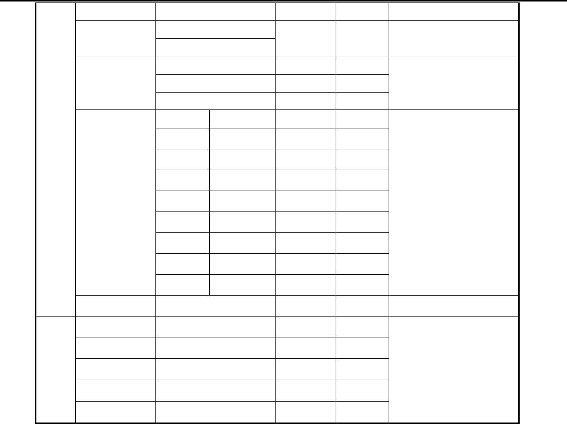
6.2 Operational steps:
1. Connection: connect PC to PCBA with signal cable, and then keep AC and DC in open state.
Acer Acer –LCD-H243H
11
2. Adjust ISP programming
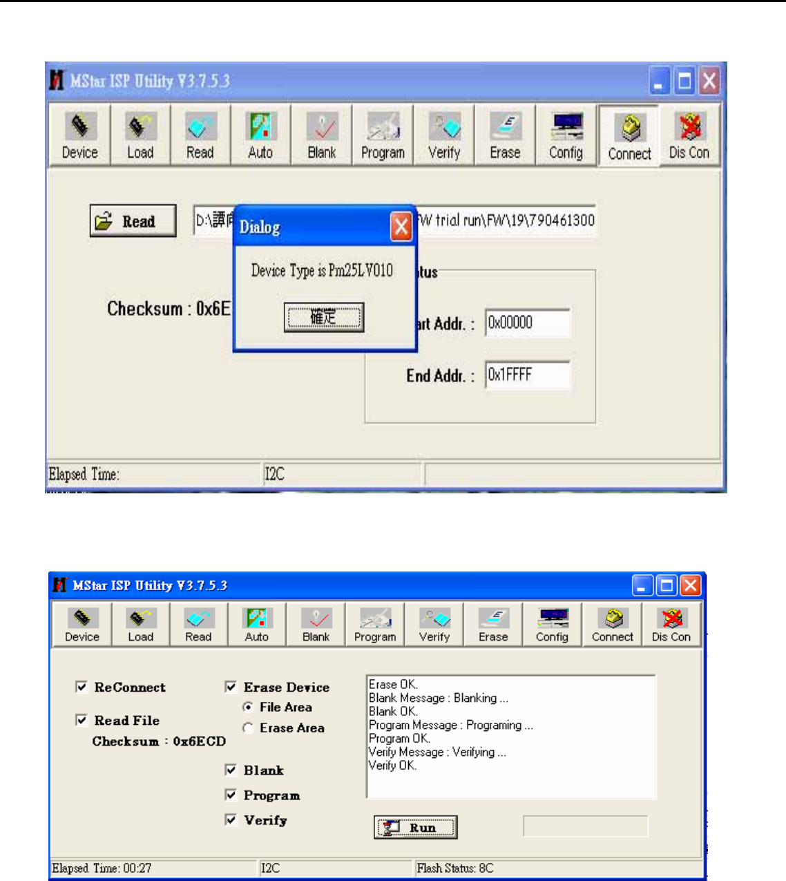
Firstly, double click ISP_Tool_v3.7.5EXEI and open ISP program, then select “Device”, next select manufacturer model of
FW IC, which should be correspondent with that of PCBA FW IC. Double click Figure One.
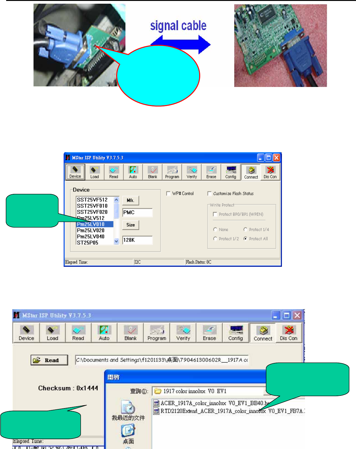
Secondly﹐download FW software: first select “READ”, and then load FW software in Rooter (Fig.2).
FW IC
Model
Software
Checksum
FW software
rooter
One port of ISP
program card
is connected to
PC print port.
Acer Acer –LCD-H243H
12
Thirdly, select “Connect” and enter ISP MODE as in the following Figure 3.
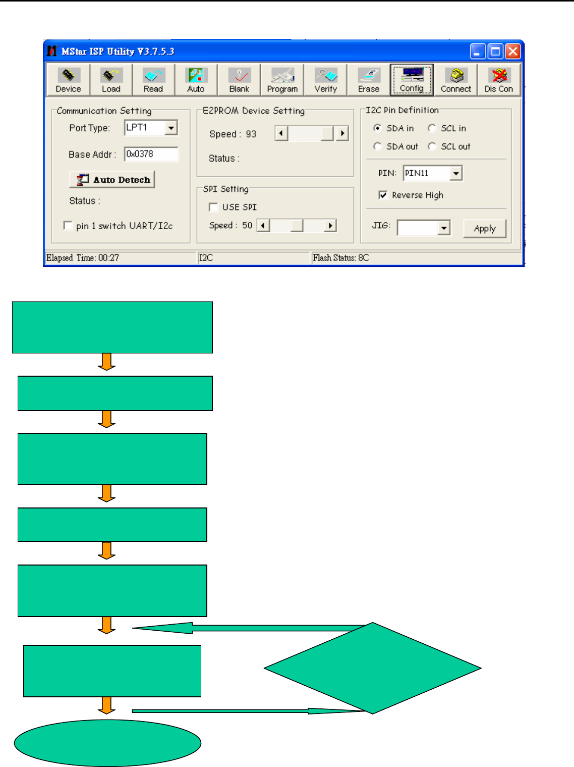
Fourthly, select “AUTO”, and keep its default value. Click “RUN” for beginning programming. There will be prompting if
programming is OK.
Acer Acer –LCD-H243H
13
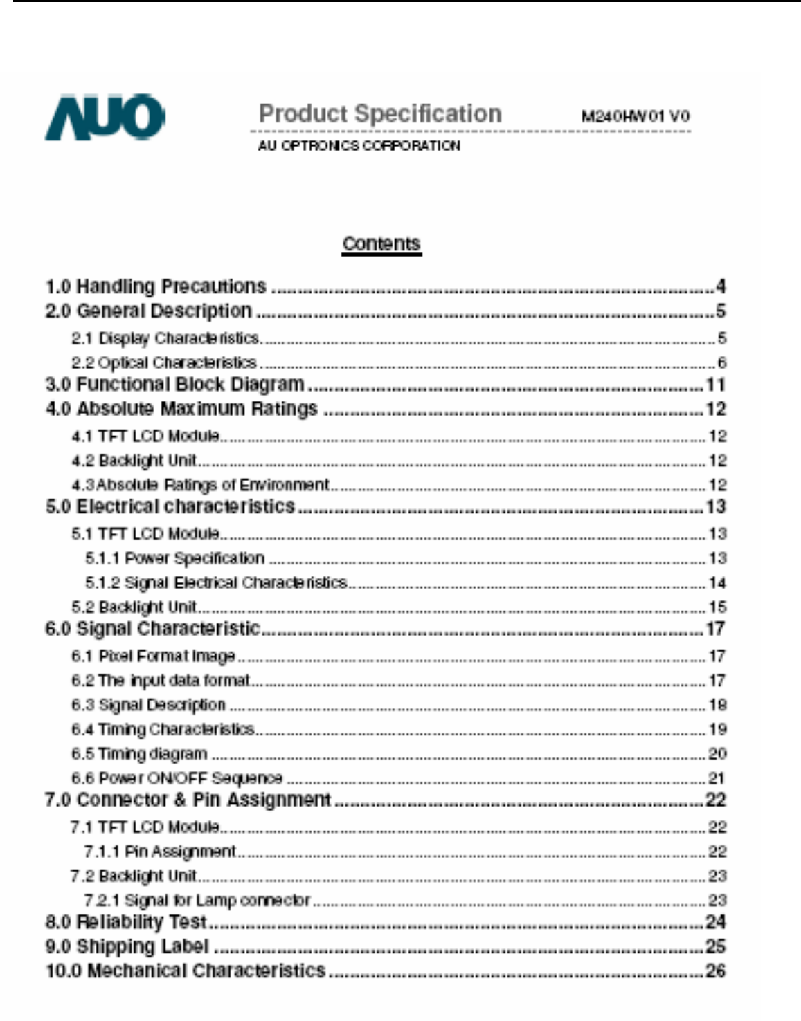
Note: if programming fails or success rate is not high, click “Config” and adjust its speed in “E2PROM DEVICE SETTING”
◆Flowin
g
chart
After connecting, AC ON,
DC ON
Open ISP program
Choose manufacturer
and model of FW IC
LOAD FW software
Click Connect and enter
ISP MODE
Click AUTO and RUN for
beginning programming
Turn off power if
p
ro
g
rammin
g
is O
K
OK
OK
OK
OK
OK
OK NG
Choose Config
and adjust
programming
Acer Acer –LCD-H243H
14
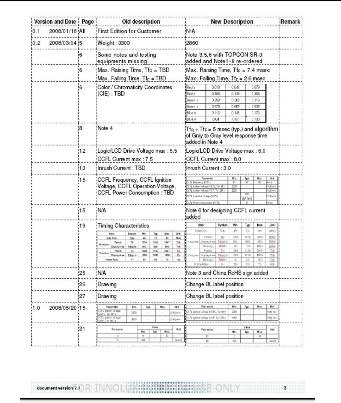
2. Flat Panel Specification
Acer Acer –LCD-H243H
15
Acer Acer –LCD-H243H
16
Acer Acer –LCD-H243H
17
Acer Acer –LCD-H243H
18
Acer Acer –LCD-H243H
19
Acer Acer –LCD-H243H
20
Acer Acer –LCD-H243H
21
Acer Acer –LCD-H243H
22
Acer Acer –LCD-H243H
23
Acer Acer –LCD-H243H
24
Acer Acer –LCD-H243H
25
Acer Acer –LCD-H243H
26
Acer Acer –LCD-H243H
27
Acer Acer –LCD-H243H
28
Acer Acer –LCD-H243H
29
Acer Acer –LCD-H243H
30
Acer Acer –LCD-H243H
31
Acer Acer –LCD-H243H
32
Acer Acer –LCD-H243H
33
Acer Acer –LCD-H243H
34
Acer Acer –LCD-H243H
35
Acer Acer –LCD-H243H
36
Acer Acer –LCD-H243H
37
Acer Acer –LCD-H243H
38
Acer Acer –LCD-H243H
39
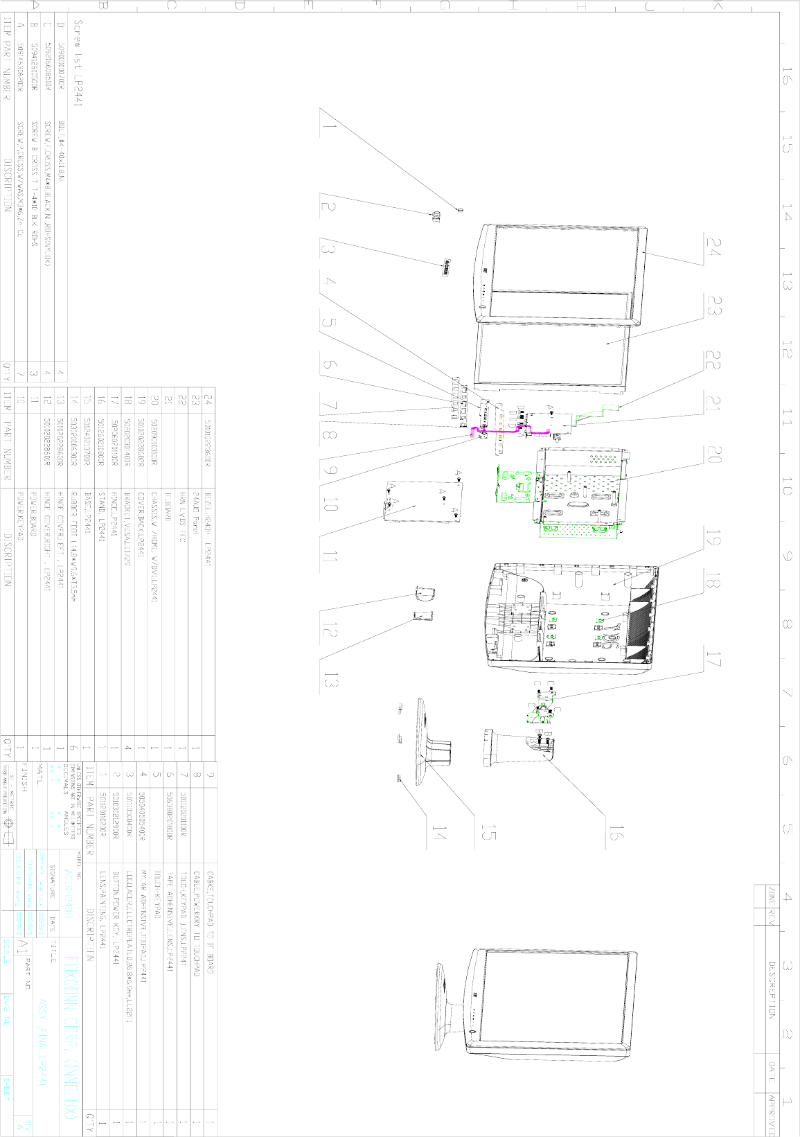
03 Exploded Diagram
3.1 H243H_SCREW_LIST
ITEM PN Description
Q'T
Y(P
CS)
Fixed
T(kg*cm) Remark
1 509146306
200R
SCREW,P,CROSS,W/WAS
,M3*6,Zn-Cc 7 6.5±0.5 For
NVBD/PWRBD/HDMI
2 509216608
110R
SCREW,F,CROSS,M4*8,B
LACK,NL,ROHS(NYLOK
)
4 12±1 For Hingle toBack cover
3 509412610
500R
SCREW B CROSS T
T-4*10 BLK ROHS 3 8.5±0.5 For Hingle to Stand Front
4 509000000
700R BOLT,#4-40x11.8,Ni 4 4.0±0.25 For D-SUB CON&DVI
3.2. LCD Exploded drawing (All)
Acer Acer –LCD-H243H
40
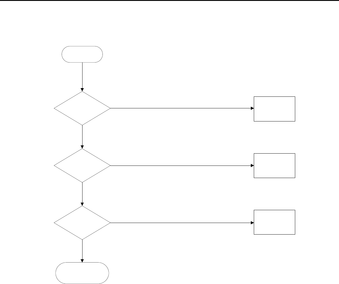
04 Troubleshooting
4.1 No Power & LED Off
yes
yes
yes
yes
NG
NG
NG
NG
NG
NG
Unstable power
Check sampling
Circuit
Check F801,
R808,R806
Change F801,
R808,R806
Check the R pin voltage
of IC803 about 2.5V
Check R832,IC801
Check
FB801,D803,C8
07,C810 if short
Change
FB801,D803,C807,
C810
Check pin6 of IC802
voltage is 14V
Check pin2 of
IC802 voltage
above 0.85V
Change R815, R 809, R848,
R 849, R850,R851,C809,
END
Check the C
pin voltage of
IC803 if 3V
Change
IC803
Acer Acer –LCD-H243H
41
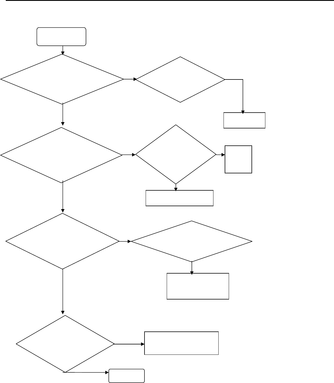
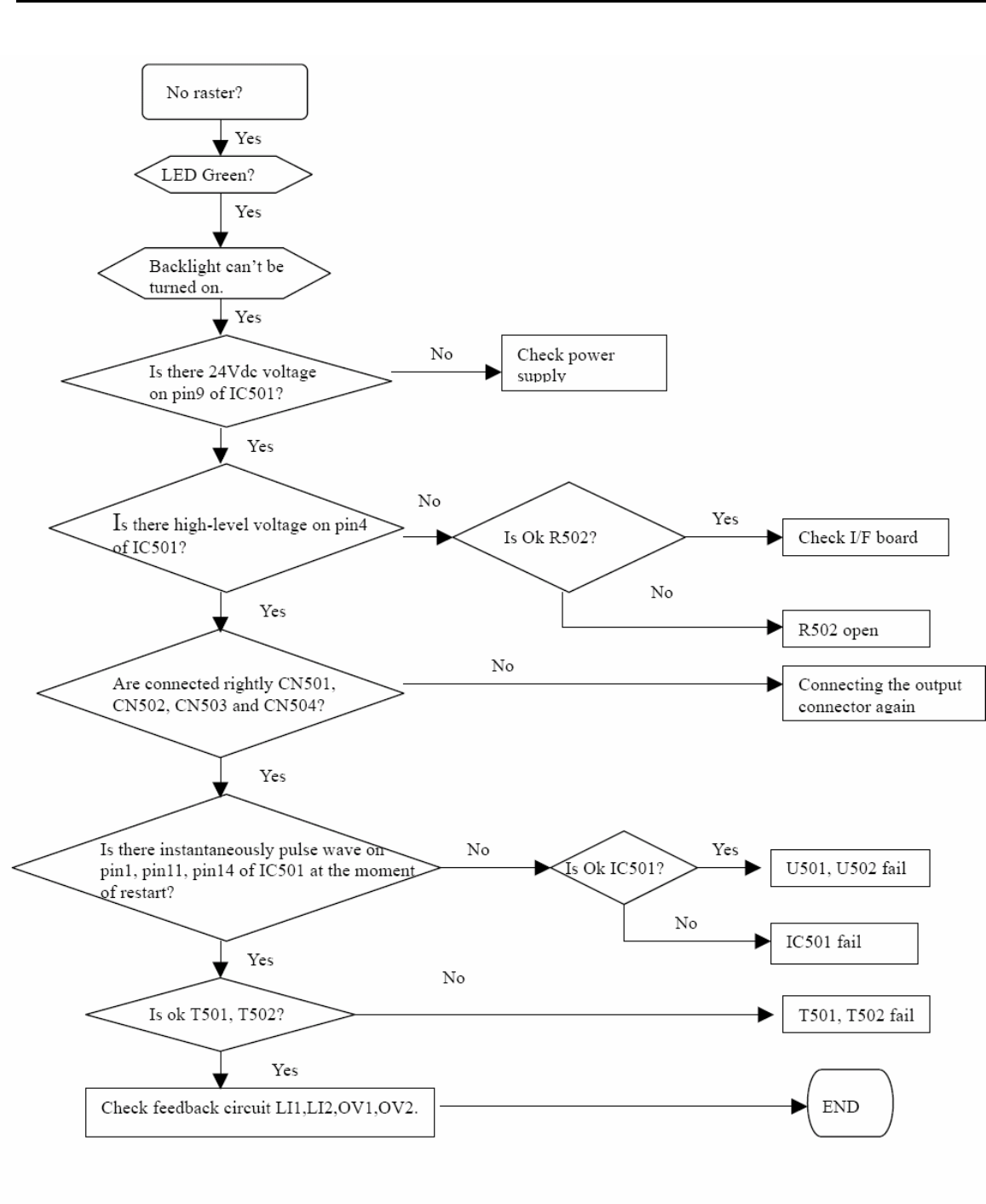
4.2 No raster
Acer Acer –LCD-H243H
42
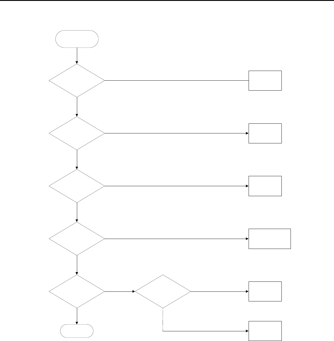
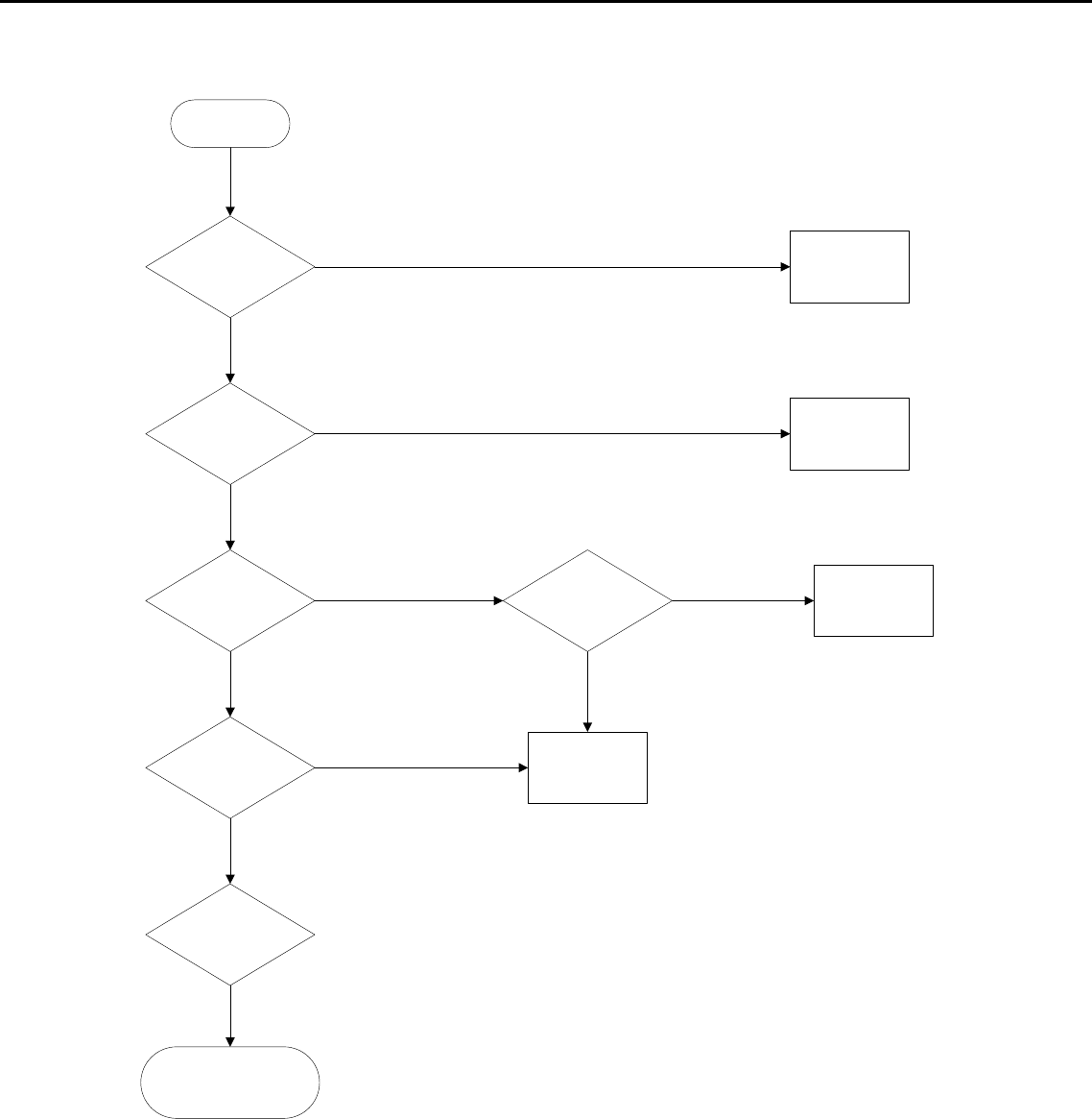
4.2 Black screen
Check power supply:
Pin 1, 2 of CN104 POWER Fail
Check U101,
U102
Check C161,
R183
Check X101, C156,
C157,R191
Inverter Fail
U104 fail
Black Screen
Check Q102,
R101, R102
Check power supply:
For U104
Check reset:
pin 8 of U104
Check Crystal
waveform
Pin 25,26 of U104
Check CCFL_Enable
Pin 101 of U104 Check Pin 7 of CN104
NG
NG
NG
NG
NG
OK
OK
OK
OK
OK
OK
NG
Acer Acer –LCD-H243H
43
4.4 Bad Screen
Bad Screen
Check LVDS
cable
Change LVDS
cable
Check Crystal:
Pin 25,26 of U104
Workmanship
LVDS cable NG
Check the pins
of U104
Change X101, C156,
C157
OK
OK
OK
NG
NG
NG
Acer Acer –LCD-H243H
44
4.5 White screen
White Screen
Check LVDS
Cable Insert OK?
Change LVDS
Cable
Check VLCD is
+5V?
Check Panel
Enable of U104
Check Q101,
Q104, Q105, R105,
R108
Check LVDS cable
U104 Fail
Workmanship
LVDS cable NG
Panel NG
Q101, Q104, Q105,
R105, R108 fail
OK
OK
OK
OK
NG
OK
NG
NG
NG
NG
NG
Acer Acer –LCD-H243H
45
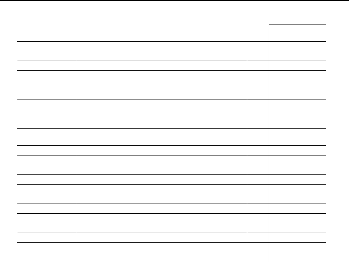
05 Spare parts List
82424171A120R
OEM PART NO DESCRIPTION MOQ N/A
792381300701R PCBA,I/F BOARD(EMEA,W/SPK),LP2441-717 RO 50 1
792381400700R PCBA,P/I BOARD,W/SPK,LP2441-717 ROHS 50 1
792381500000R PCBA,POWER KYEPAD/B,LP2441 ROHS 50 1
792381500010R PCBA,TOUCHPAD BOARD,LP2441 ROHS 50 1
453070801190R PWRCORD 16A/250V BLK 6FT VDE/KTL H05VV-F 50 1
453030300370R CABLE,DVI-D 18+1P MALE 6FT BLACK , ROHS 50 1
453030300371R CABLE,DVI-D 18+1P MALE 6FT BLACK 50 1
453010100380R CABLE,D-SUB 15P MALE 6FT BLACK/BLUE, ROH 50 1
453030300120R CABLE AUDIO 1P 6FT BLACK/GREEN
CP03B06P0 50 1
430303002230R HRN LVDS FFC 30P 166.5mm W/TASTE 50 1
430300400390R HRN ASS'Y 4P 27MM UL1571#28 50 1
430300802060R HRN ASSY, 2X4P TO 1X8P ,220mm,UL1571#28 50 1
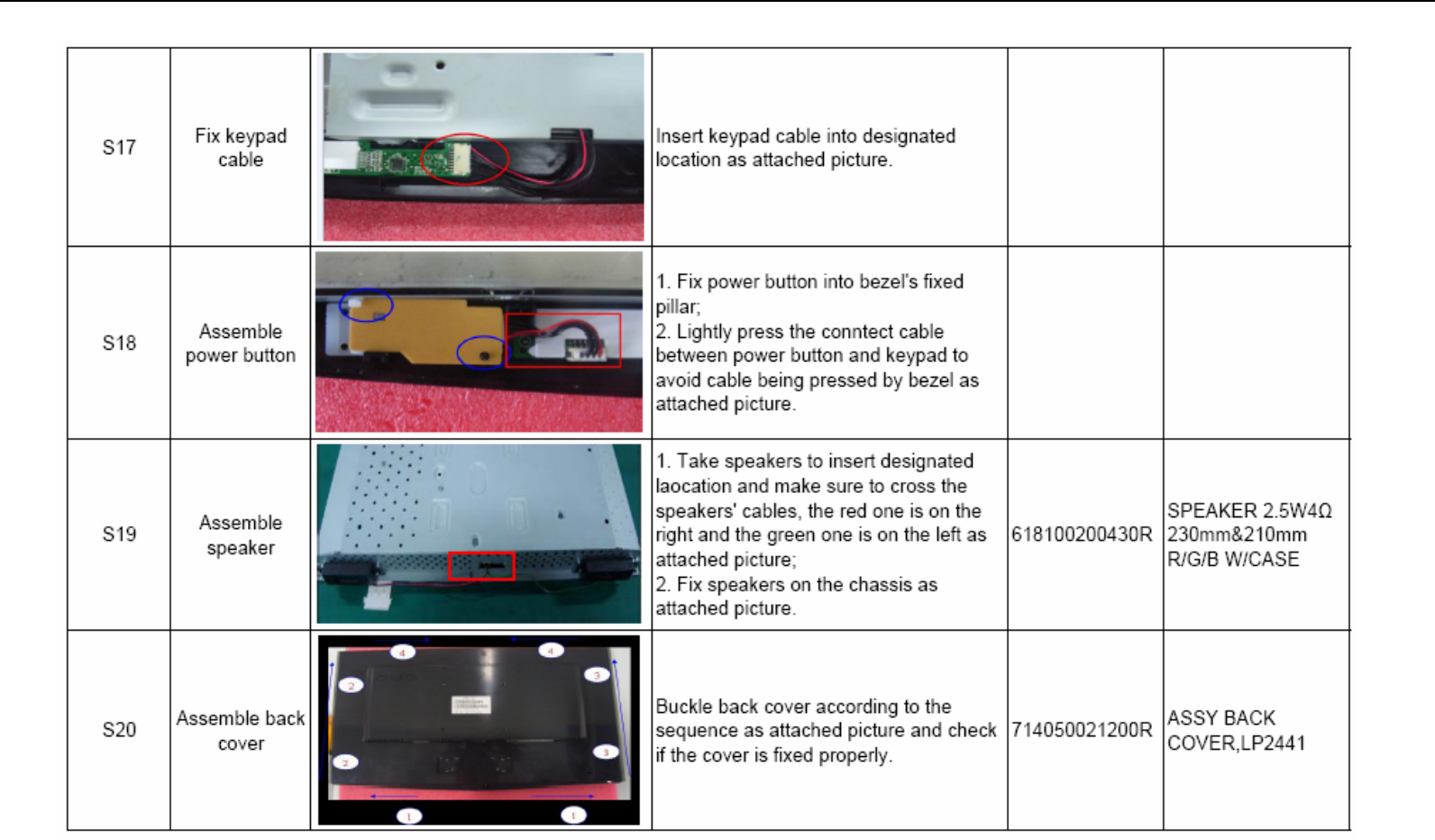
714050021200R ASSY BACK COVER,LP2441 50 1
714030022100R ASSY BEZEL ,LP2441 50 1
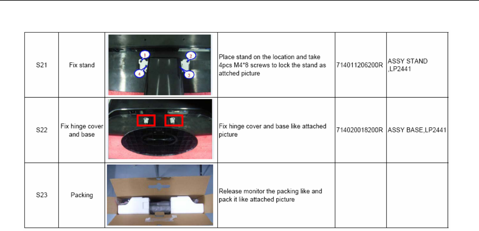
714011206200R ASSY STAND ,LP2441 50 1
714020018200R ASSY BASE,LP2441 50 1
501020228602R COVER,BACK,LP2441 50 1
502060201100R HINGE,LP2441 50 1
501260210800R STAND, LP2441 50 1
502090103100R CHASSIS,W /HDMI, W/DVI,LP2441 50 1
631102240130R LCP 24" M240HW01-V0-00(A)(AUO)ROHS 50 1
Acer Acer –LCD-H243H
46
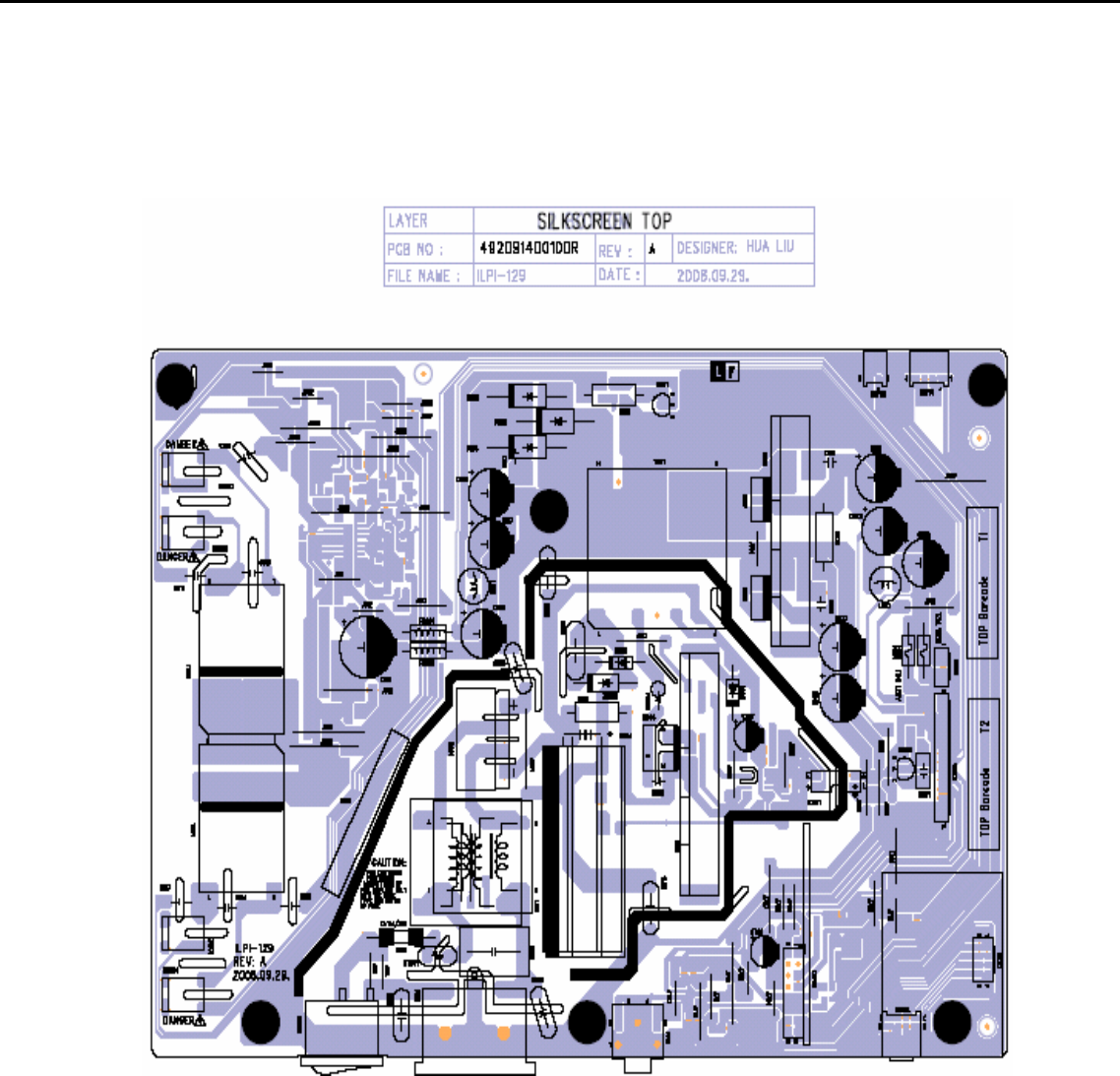
06 Schematics and Layouts
6.1 PI BD Layout
Acer Acer –LCD-H243H
47
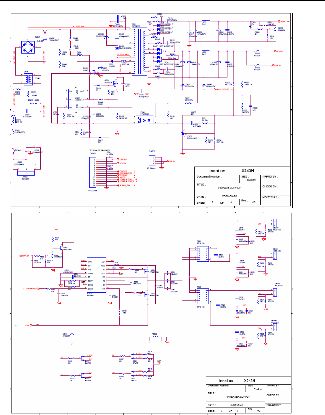
6.2 Switching Mode Power Supply circuit
Acer Acer –LCD-H243H
48
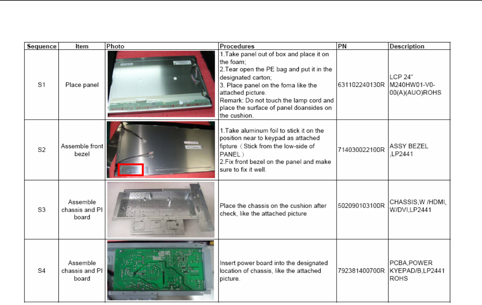
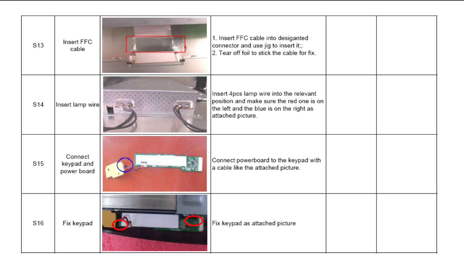
7.0 Assembly and Disassembly
The tool of Assembly and disassembly : 1) Electrostatic gloves 2) Electric screwdriver: the lengthe of screwdriver top is 6±0.5cm and
15±0.5cm ; the diameter of screwdriver top is Φ5*H5mm
Acer Acer –LCD-H243H
49
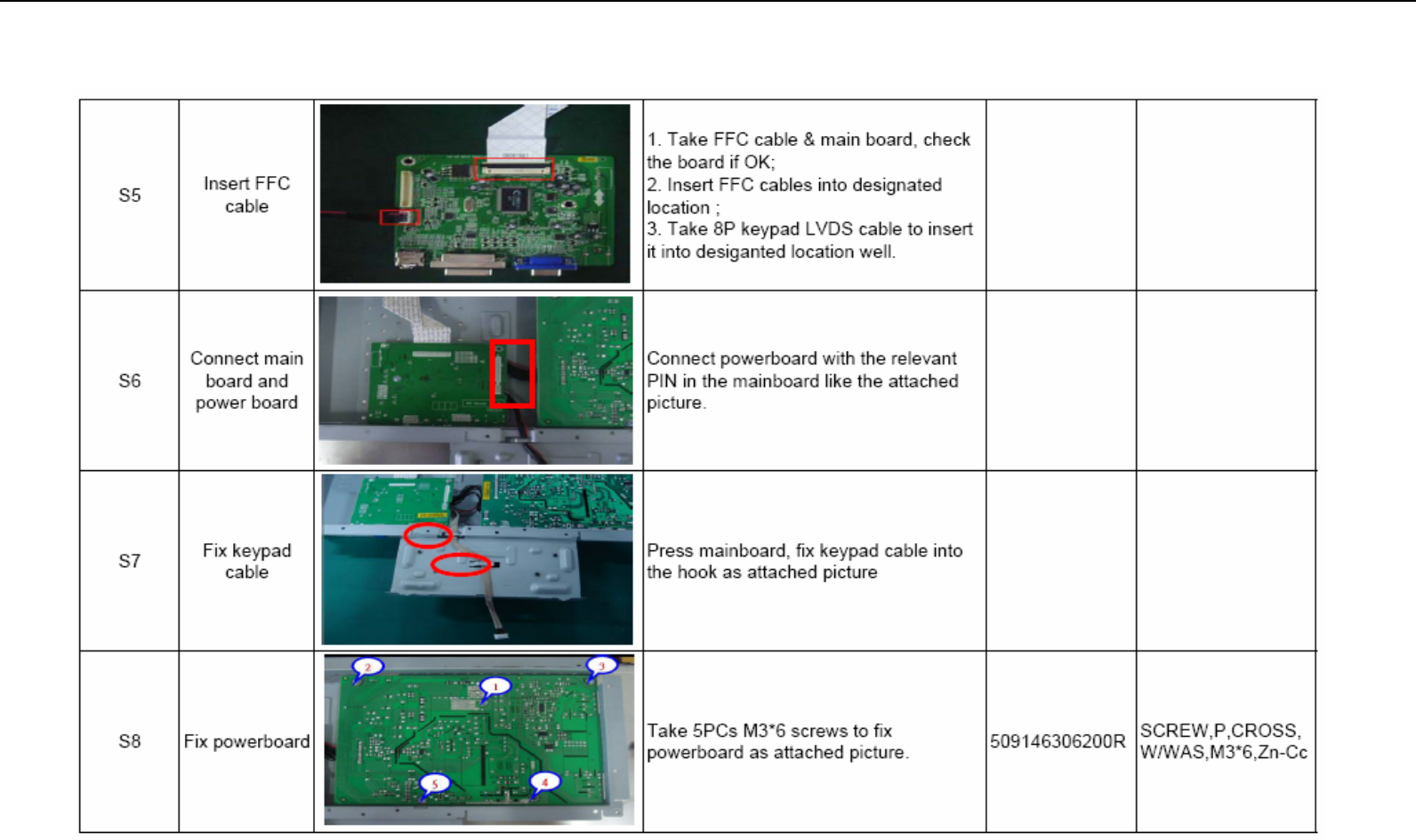
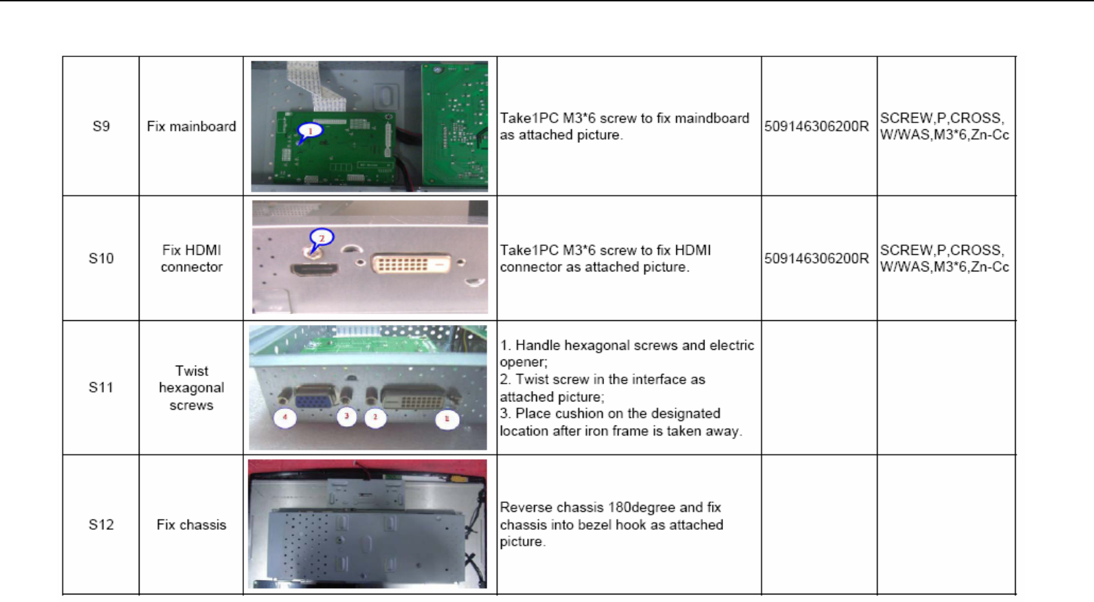
Assembly and Disassembly (continue)
Acer Acer –LCD-H243H
50
Assembly and Disassembly (continue)
Acer Acer –LCD-H243H
51
Assembly and Disassembly (continue)
Acer Acer –LCD-H243H
52
Assembly and Disassembly (continue)
Acer Acer –LCD-H243H
53
Assembly and Disassembly (continue)
