Acer M3920 ASerena Aspire SG User Manual To The 6e7b9ce2 Ce51 4da9 84ba B443bce0aaa6
User Manual: Acer M3920 to the manual
Open the PDF directly: View PDF ![]() .
.
Page Count: 98
- Acer Aspire M3920 Service Guide
- System Utilities
- System Disassembly
- Disassembly Requirements
- Pre-disassembly Procedure
- Removing the Side Panel
- Removing the Heatsink Fan Assembly
- Removing the Processor
- Removing the VGA Card
- Removing the Mode Card
- Removing the TV Card
- Removing the Memory Modules
- Removing the Hard Disk Drive
- Removing the USB Board
- Removing the Front Bezel
- Removing the Optical Drive
- Removing the Removable HDD
- Removing the Card Reader
- Removing the Power Supply
- Removing the Mainboard
- System Troubleshooting
- System Architecture
- FRU (Field Replaceable Unit) List

Acer
Aspire M3920
Service Guide

ii
Revision History
Please refer to the table below for the updates made on this service guide.
Date Chapter Updates

iii
Copyright
Copyright © 2010 by Acer Incorporated. All rights reserved. No part of this publication may be reproduced,
transmitted, transcribed, stored in a retrieval system, or translated into any language or computer language, in
any form or by any means, electronic, mechanical, magnetic, optical, chemical, manual or otherwise, without
the prior written permission of Acer Incorporated.

iv
Disclaimer
The information in this guide is subject to change without notice.
Acer Incorporated makes no representations or warranties, either expressed or implied, with respect to the
contents hereof and specifically disclaims any warranties of merchantability or fitness for any particular
purpose. Any Acer Incorporated software described in this manual is sold or licensed "as is". Should the
programs prove defective following their purchase, the buyer (and not Acer Incorporated, its distributor, or its
dealer) assumes the entire cost of all necessary servicing, repair, and any incidental or consequential
damages resulting from any defect in the software.
Acer is a registered trademark of Acer Corporation.
Intel is a registered trademark of Intel Corporation.
Pentium Dual-Core, Celeron Dual-Core, Core 2 Duo, Core 2 Quad, Celeron, and combinations thereof, are
trademarks of Intel Corporation.
Other brand and product names are trademarks and/or registered trademarks of their respective holders.

v
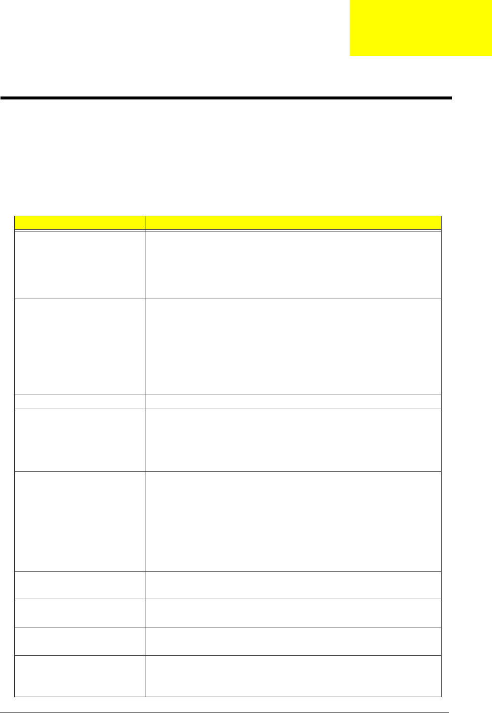
Conventions
The following conventions are used in this manual:
SCREEN
MESSAGES
Denotes actual messages that appear on screen.
NOTE Gives additional information related to the current topic.
WARNING Alerts you to any physical risk or system damage that might result from doing
or not doing specific actions.
CAUTION Gives precautionary measures to avoid possible hardware or software
problems.
IMPORTANT Reminds you to do specific actions relevant to the accomplishment of
procedures.

vi
Service Guide Coverage
This Service Guide provides you with all technical information relating to the BASIC CONFIGURATION
decided for Acer's "global" product offering. To better fit local market requirements and enhance product
competitiveness, your regional office MAY have decided to extend the functionality of a machine (e.g. add-on
card, modem, or extra memory capability). These LOCALIZED FEATURES will NOT be covered in this generic
service guide. In such cases, please contact your regional offices or the responsible personnel/channel to
provide you with further technical details.
FRU Information
Please note WHEN ORDERING FRU PARTS, that you should check the most up-to-date information available
on your regional web or channel. If, for whatever reason, a part number change is made, it will not be noted in
the printed Service Guide. For ACER-AUTHORIZED SERVICE PROVIDERS, your Acer office may have a
DIFFERENT part number code to those given in the FRU list of this printed Service Guide. You MUST use the
list provided by your regional Acer office to order FRU parts for repair and service of customer machines.

vii
Table of Contents
Features and Specifications ................................................................... 1
System Features . . . . . . . . . . . . . . . . . . . . . . . . . . . . . . . . . . . . . . . . . . . . . . . . . . . . . .1
Audio . . . . . . . . . . . . . . . . . . . . . . . . . . . . . . . . . . . . . . . . . . . . . . . . . . . . . . . . . . . . . . .2
I/O Ports and LED Indicators . . . . . . . . . . . . . . . . . . . . . . . . . . . . . . . . . . . . . . . . . . . . . .2
Physical Specifications . . . . . . . . . . . . . . . . . . . . . . . . . . . . . . . . . . . . . . . . . . . . . . . . . .3
Environmental Requirements . . . . . . . . . . . . . . . . . . . . . . . . . . . . . . . . . . . . . . . . . . . . .3
Power Management Function(ACPI support function) . . . . . . . . . . . . . . . . . . . . . . . . . .3
System Tour . . . . . . . . . . . . . . . . . . . . . . . . . . . . . . . . . . . . . . . . . . . . . . . . . . . . . . . . . 4
Front View . . . . . . . . . . . . . . . . . . . . . . . . . . . . . . . . . . . . . . . . . . . . . . . . . . . . . . 4
Rear View . . . . . . . . . . . . . . . . . . . . . . . . . . . . . . . . . . . . . . . . . . . . . . . . . . . . . . . 5
System Utilities ....................................................................................... 7
CMOS Setup Utility . . . . . . . . . . . . . . . . . . . . . . . . . . . . . . . . . . . . . . . . . . . . . . . . . . 7
Entering CMOS setup . . . . . . . . . . . . . . . . . . . . . . . . . . . . . . . . . . . . . . . . . . . . . 8
Navigating Through the Setup Utility . . . . . . . . . . . . . . . . . . . . . . . . . . . . . . . . . . .8
Setup Utility Menus . . . . . . . . . . . . . . . . . . . . . . . . . . . . . . . . . . . . . . . . . . . . . . . .9
System Disassembly ............................................................................. 21
Disassembly Requirements . . . . . . . . . . . . . . . . . . . . . . . . . . . . . . . . . . . . . . . . . . . . . .21
Pre-disassembly Procedure . . . . . . . . . . . . . . . . . . . . . . . . . . . . . . . . . . . . . . . . . . . . .21
Removing the Side Panel . . . . . . . . . . . . . . . . . . . . . . . . . . . . . . . . . . . . . . . . . . . 22
Removing the Heatsink Fan Assembly . . . . . . . . . . . . . . . . . . . . . . . . . . . . . . . . . .23
Removing the Processor . . . . . . . . . . . . . . . . . . . . . . . . . . . . . . . . . . . . . . . . . . . .24
Removing the VGA Card . . . . . . . . . . . . . . . . . . . . . . . . . . . . . . . . . . . . . . . . . . .26
Removing the Mode Card . . . . . . . . . . . . . . . . . . . . . . . . . . . . . . . . . . . . . . . . . .27
Removing the TV Card . . . . . . . . . . . . . . . . . . . . . . . . . . . . . . . . . . . . . . . . . . . . .28
Removing the Memory Modules . . . . . . . . . . . . . . . . . . . . . . . . . . . . . . . . . . . . . 28
Removing the Hard Disk Drive . . . . . . . . . . . . . . . . . . . . . . . . . . . . . . . . . . . . . . . 29
Removing the USB Board . . . . . . . . . . . . . . . . . . . . . . . . . . . . . . . . . . . . . . . . . . .32
Removing the Front Bezel . . . . . . . . . . . . . . . . . . . . . . . . . . . . . . . . . . . . . . . . . . .35
Removing the Optical Drive . . . . . . . . . . . . . . . . . . . . . . . . . . . . . . . . . . . . . . . . . 37
Removing the Removable HDD . . . . . . . . . . . . . . . . . . . . . . . . . . . . . . . . . . . . . . 39
Removing the Card Reader . . . . . . . . . . . . . . . . . . . . . . . . . . . . . . . . . . . . . . . . . .43
Removing the Power Supply . . . . . . . . . . . . . . . . . . . . . . . . . . . . . . . . . . . . . . . . .46
Removing the Mainboard . . . . . . . . . . . . . . . . . . . . . . . . . . . . . . . . . . . . . . . . . .48
System Troubleshooting ...................................................................... 51
Hardware Diagnostic Procedure . . . . . . . . . . . . . . . . . . . . . . . . . . . . . . . . . . . . . .51
System Check Procedures . . . . . . . . . . . . . . . . . . . . . . . . . . . . . . . . . . . . . . . . . . .52
Power System Check . . . . . . . . . . . . . . . . . . . . . . . . . . . . . . . . . . . . . . . . . . . . . .52
System External Inspection . . . . . . . . . . . . . . . . . . . . . . . . . . . . . . . . . . . . . . . . . 52
System Internal Inspection . . . . . . . . . . . . . . . . . . . . . . . . . . . . . . . . . . . . . . . . . .52
Beep Codes . . . . . . . . . . . . . . . . . . . . . . . . . . . . . . . . . . . . . . . . . . . . . . . . . . . . .53
Checkpoints . . . . . . . . . . . . . . . . . . . . . . . . . . . . . . . . . . . . . . . . . . . . . . . . . . . . .54
Viewing BIOS checkpoints . . . . . . . . . . . . . . . . . . . . . . . . . . . . . . . . . . . . . . . . . .54
Bootblock Initialization Code Checkpoints . . . . . . . . . . . . . . . . . . . . . . . . . . . . . .54
Bootblock Recovery Code Checkpoints . . . . . . . . . . . . . . . . . . . . . . . . . . . . . . . . .56
BIOS Recovery . . . . . . . . . . . . . . . . . . . . . . . . . . . . . . . . . . . . . . . . . . . . . . . . . . .57
System Architecture ............................................................................. 59
Block Diagram . . . . . . . . . . . . . . . . . . . . . . . . . . . . . . . . . . . . . . . . . . . . . . . . . . . . . . .59
Mainboard Layout . . . . . . . . . . . . . . . . . . . . . . . . . . . . . . . . . . . . . . . . . . . . . . . .60
Jumper Setting . . . . . . . . . . . . . . . . . . . . . . . . . . . . . . . . . . . . . . . . . . . . . . . . . . .61

viii
Table of Contents
Jumper Setting . . . . . . . . . . . . . . . . . . . . . . . . . . . . . . . . . . . . . . . . . . . . . . . . . . .61
Connecting Optional Devices . . . . . . . . . . . . . . . . . . . . . . . . . . . . . . . . . . . . . . . .65
Connecting Case Components . . . . . . . . . . . . . . . . . . . . . . . . . . . . . . . . . . . . . . .67
FRU (Field Replaceable Unit) List ......................................................... 69
Aspire M3920 Exploded Diagram . . . . . . . . . . . . . . . . . . . . . . . . . . . . . . . . . . . . . . . . .70
Aspire M3920 FRU List . . . . . . . . . . . . . . . . . . . . . . . . . . . . . . . . . . . . . . . . . . . . . . .71
Chapter 1 1
This chapter lists the features and specifications of this computer.
System Features
NOTE The items listed in this section are for reference only. The exact configuration of your PC depends
on the model purchased. Refer to the FRU list chapter on page 69 for a detailed list of models
supported by each hardware component.
Component Description
Operating system support • Microsoft Windows 7 Home Premium (X64/X86)
• Microsoft Windows 7 Home Basic (X64/X86)
• Microsoft Windows 7 Starter X86
• Linpus Linux x-Window mode
•Free Dos
Processor • LGA-1155 socket
• Supports the following Intel processors:
– Core i7 2600 3.4G 8M 1333 95W D-2
– Core i5 2500 6M 1333 95W D-2 3.3G
– Core i5 2400 6M 1333 95W D-2, quad core
– Core i5 2300 2.8G 6M 1333 95W D-2
– Core i3-2120 3.3GHz 2C/4T 3MB
– Core i3-2100 3.1GHz 2C/4T 3MB
Chipset • PCH: Intel H67
Graphics • Intel® HD Graphics Support (supported by CPU)
– Dual independent display
– Digital display (HDMI/DVI/DP/eDP) and VGA
• DVMT 5.0 technology support
• Enhanced 3D and Clear Video technology support
Memory • Four DIMM sockets (two channels, two slots per channel)
• Dual channel support
– Channel A: slot 0, 1; Channel B: slot 2, 3
– Different colors for slot 0/2 and slot 1/3
• Supports 1GB, 2 GB and 4GB DDR III Unbuffered Non-ECC DIMM
modules
• Data rates supported: 800/1066/1333 MT/s
• Maximum memory: 16 GB (using 4 GB modules)
Expansion options • One PCIE x16 (PCIE V2.0) slot
• Three PCIE x1 (PCIE V2.0) slots
Connectivity • Wired LAN: GigaLAN
• WLAN option: 802.11 b/g/n wireless network adapter
Hard disk drive (HDD) • Supports up to three 3.5-inch 25.4 mm SATA HDDs
• Capacity and models are listed in FRU list
Optical disc drive (ODD) • Suports up to two 5.25-inch standard SATA ODDs
• Supports DVD-ROM, DVD-SuperMulti, BD-combo, BD-rewrite
• Models are listed in FRU list
Features and Specifications
Chapter 1
2Chapter 1
Audio
I/O Ports and LED Indicators
Card reader (optional) • 16-in-1 card reader (optional)
• The following memory cards are supported:
– Memory Stick (MS),Memory Stick Pro, Memory Stick Micro (M2)
– xD-Picture Card (xD)
– Secure Digital (SD), MultiMediaCard (MMC)
– CompactFlash, Type I/II (CF, Type I and II)
– Memory Stick PRO (MS PRO)
TV tuner (optional) • Avermedia H753-A TV Tuner Card PCIe Hybrid ATSC card
• Avermedia H753-D TV Tuner Card PCIe Hybrid DVB-T card
• Avermedia H753-C TV Tuner Card PCIe Hybrid DMB-TH card
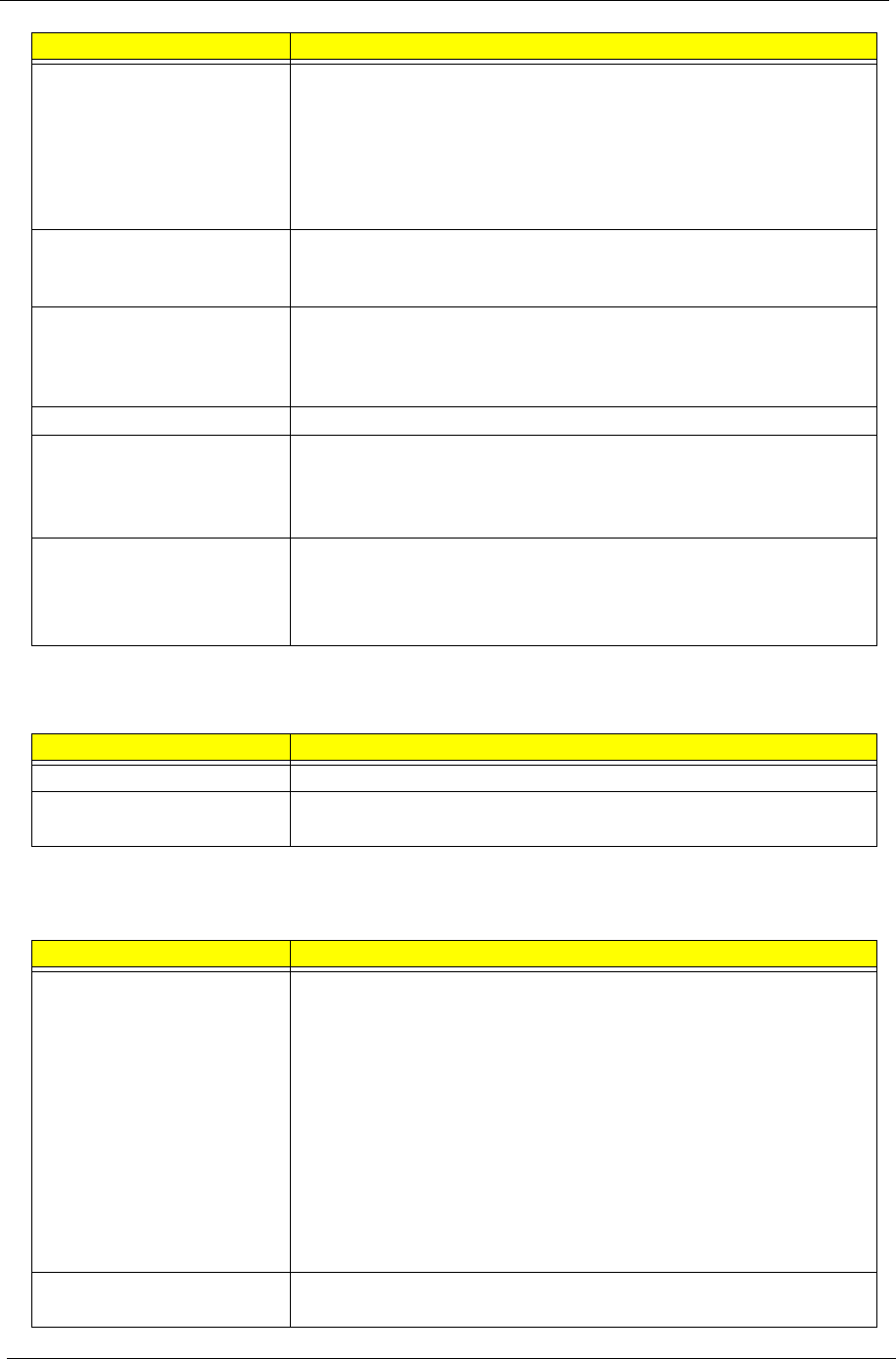
Power supply • 300 W power supply unit (non-PFC, non-power factor correction),
100-127V/220-240V (4SATA1PATA) co-module
• 300 W power supply unit (PFC), 100-127v/220v-240V
(4SATA1PATA) co-module
Antivirus software Norton Internet Security
System BIOS • AMI Kernel with Acer skin
• Supports ACPI revision 2.0 standard
• Supports Plug and Play, STR(S3)/STD(S4), hardware monitor, Multi Boot,
and DMI protocols
Power management • ACPI 2.0 or 1.0b (Advanced Configuration Power Interface) standard
• S0, S1, S2 and S5 sleep states support
• On-board device power management support
• On-board device configuration support
Item Description
Audio codec • Realtek ALC662 5.1 Channel High Definition Audio Codec
Audio jacks • Front panel: Headphone and microphone jacks
• Rear panel: Microphone, line-out, and line-in jacks
Component Description
I/O ports • Front panel
– Four USB ports
– One headphone jack
– One microphone jack
– 16-in-1 card reader
• Rear panel
– One PS/2 keyboard
– One PS/2 mouse port
– External display (VGA) port
– One HDMI port
– Eight USB ports
– One Ethernet jack (RJ45)
– Microphone, line-out, and line-in jacks
LED indicators • Hard drive activity
• Power status
Component Description

Chapter 1 3
Physical Specifications
Environmental Requirements
Power Management Function(ACPI support function)
Device Standby Mode
•Independent power management timer for hard disk drive devices (0-15 minutes,time step=1minute).
•Hard Disk drive goes into Standby mode(for ATA standard interface).
•Disable V-sync to control the VESA DPMS monitor.
•Resume method:device activated (keyboard for DOS, keyboard &mouse for Windows.
•Resume recovery time 3-5sec
Global Standby Mode
•Global power management timer (2-120minutes,time step=10minute).
•Hard disk drive goes into Standby mode(for ATA standard interface).
•Disable H-sync and V-sync signals to control the VESA DPMS monitor.
• Resume method: Resume to original state by pushing external switch Button,modem ring in,keyboard
an mouse for APM mode.
•Resume recovery time :7-10sec
Suspend Mode
•Independent power management timer(2-120minutes,time step=10minute)or pushing extern switch
button.
•CPU goes into SMM
•CPU asserts STPCLK# and goes into the Stop Grant State.
• LED on panel turns amber colour.
•Hard disk drive goes into SLEEP mode (for ATA standard interface).
•Disable H-sync and V-sync signals to control the VESA DPMS monitor.
•Ultra I/O and VGA chip go into power saving mode.
•Resume method: Resume to original state by pushing external switch Button,modem ring in,keyboard
an mouse for APM mode
•Return to original state by pushing external switch button,modem ring in and USB keyboard for ACPI
mode.
Aspect Description
Chassis dimension (W × D × H) 180 mm (W) x 401.8 mm (D) x 379 mm (H)
System weight 8.168 kg.
Mainboard form factor MicroATX (µATX)
Mainboard dimensions (W × H) 244 mm x 244 mm
Aspect Description
Operating temperature 5 to 35 °C (41 to 95 °F)
Operating humidity 15% to 80% RH non-condensing
4Chapter 1
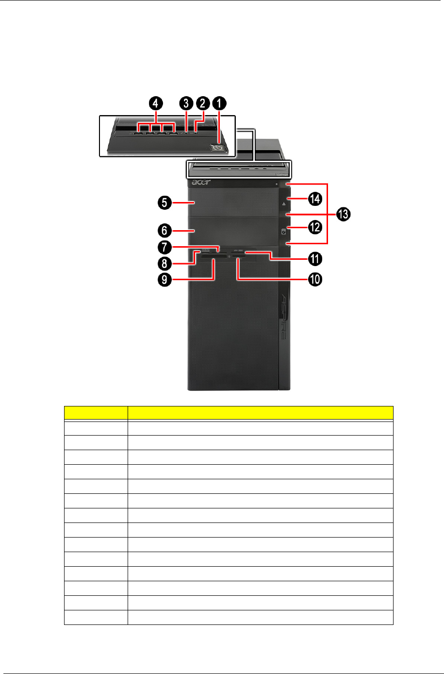
System Tour
The pictures and tables in this section illustrate the physical outlook of the computer.
Front View
No. Component
1 Power button
2 Headphone/Speaker-out/line-out jack
3 Microphone-in jack
4 USB 2.0 ports
5 Master optical drive bay door
6 Slave bay door (optical drive bay, removable HDD bay)
7XD slot
8 Memory Stick / Micro Secure Digital
9 CF I/II (CompactFlash Type I/II) slot
10 Memory Stick / Memory Stick Pro.
11 Secure Digital / Multi media card
12 Master optical drive button
13 Cosmetic LED
14 Slave optical drive button
Chapter 1 5
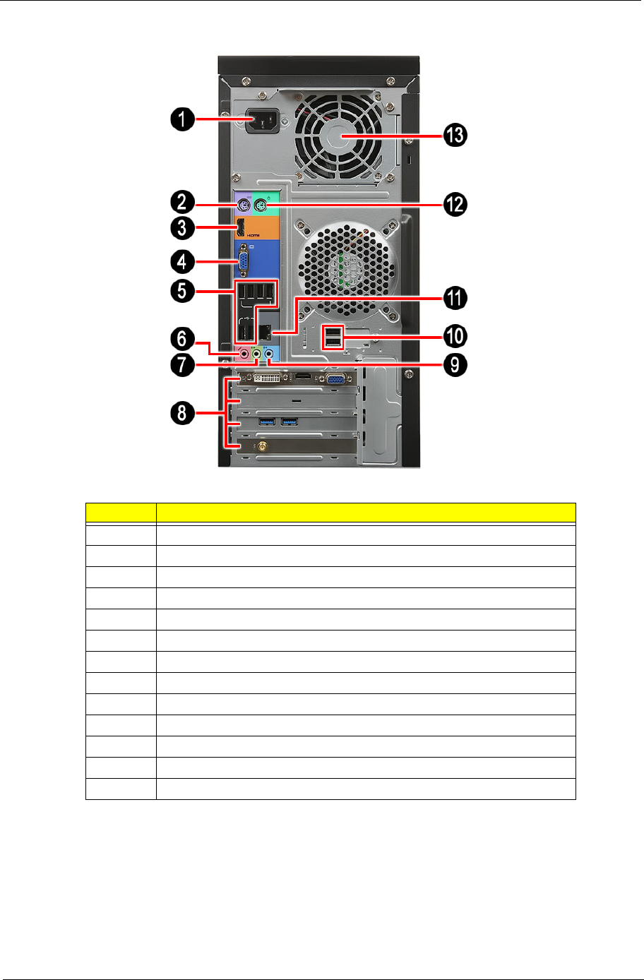
Rear View
No. Component
1 Power connector
2 PS2 keyboard port
4VGA port
3 HDMI port
5 USB 2.0 ports
6 Microphone
7 Line-out jack
8 Expansion slot (graphics card and TV tuner card and Mode card)
9 Line-in jack
10 USB 2.0 ports
11 RJ45 LAN connector
12 PS2 mouse port
13 System fan

6Chapter 1

Chapter 2 7
CMOS Setup Utility
CMOS setup is a hardware configuration program built into the system ROM, called the complementary metal-
oxide semiconductor (CMOS) Setup Utility. Since most systems are already properly configured and
optimized, there is no need to run this utility. You will need to run this utility under the following conditions.
•When changing the system configuration settings
•When redefining the communication ports to prevent any conflicts
•When modifying the power management configuration
•When changing the password or making other changes to the security setup
•When a configuration error is detected by the system and you are prompted ("Run Setup"
message) to make changes to the CMOS setup
NOTE: If you repeatedly receive Run Setup messages, the battery may be bad. In this case, the system
cannot retain configuration values in CMOS. Ask a qualified technician for assistance.
CMOS setup loads the configuration values in a battery-backed nonvolatile memory called CMOS RAM. This
memory area is not part of the system RAM which allows configuration data to be retained when power is
turned off.
Before you run the CMOS Setup Utility, make sure that you have saved all open files. The system reboots
immediately after you close the Setup.
NOTE: CMOS Setup Utility will be simply referred to as “BIOS”, "Setup", or "Setup utility" in this guide.
The screenshots used in this guide display default system values. These values may not be the same
those found in your system.
System Utilities
Chapter 2

8Chapter 2
Entering CMOS setup
1. Turn on the computer and the monitor.
If the computer is already turned on, close all open applications, then restart the computer.
2. During POST, press Delete.
If you fail to press Delete before POST is completed, you will need to restart the computer.
The Setup Main menu will be displayed showing the Setup’s menu bar. Use the left and right arrow keys
to move between selections on the menu bar.
Navigating Through the Setup Utility
Use the following keys to move around the Setup utility.
•Left and Right arrow keys – Move between selections on the menu bar.
•Up and Down arrow keys – Move the cursor to the field you want.
•+ and - keys – Select a value for the currently selected field (only if it is user-configurable). Press
these keys repeatedly to display each possible entry, or the Enter key to choose from a pop-up
menu.
NOTE: Grayed-out fields are not user-configurable.
•Enter key – Display a submenu screen.
NOTE: Availability of submenu screen is indicated by a (>).
•Esc – If you press this key:
•On one of the primary menu screens, the Exit menu displays.
•On a submenu screen, the previous screen displays.
•When you are making selections from a pop-up menu, closes the pop-up without making a
selection.
•F1 – Display the General Help panel.
•F7 – Press to load user default values.
•F8 – Press to save user default values.
•F9 – Press to load optimized default system values.
•F10 – Save changes made the Setup and close the utility.

Chapter 2 9
Setup Utility Menus
The Setup Main menu includes the following main setup categories.
•Main
•Advanced
•Power
•Security
•Boot Options
•Exit
In the descriptive table following each of the menu screenshots, settings in boldface are the default and
suggested settings.
10 Chapter 2
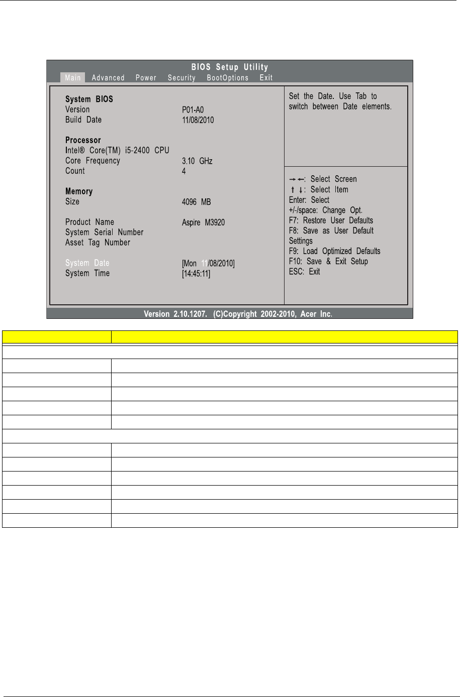
Main
The Main menu displays basic information about the system.
Parameter Description
System BIOS
Version Version number of the BIOS setup utility.
Build Date Date when the BIOS setup utility was built.
Processor Type of CPU installed on the system.
Core Frequency Core speed of the CPU installed on the system.
Count Physical CPU count
Memory
Size Total size of system memory installed on the system.
Product Name Product name of the system.
System Serial Number Serial number of the system.
Asset Tag Number Asset tag number of this system.
System Date Set the date following the weekday-month-day-year format.
System Time (hh:mm:ss) Set the system time following the hour-minute-second format.
Chapter 2 11
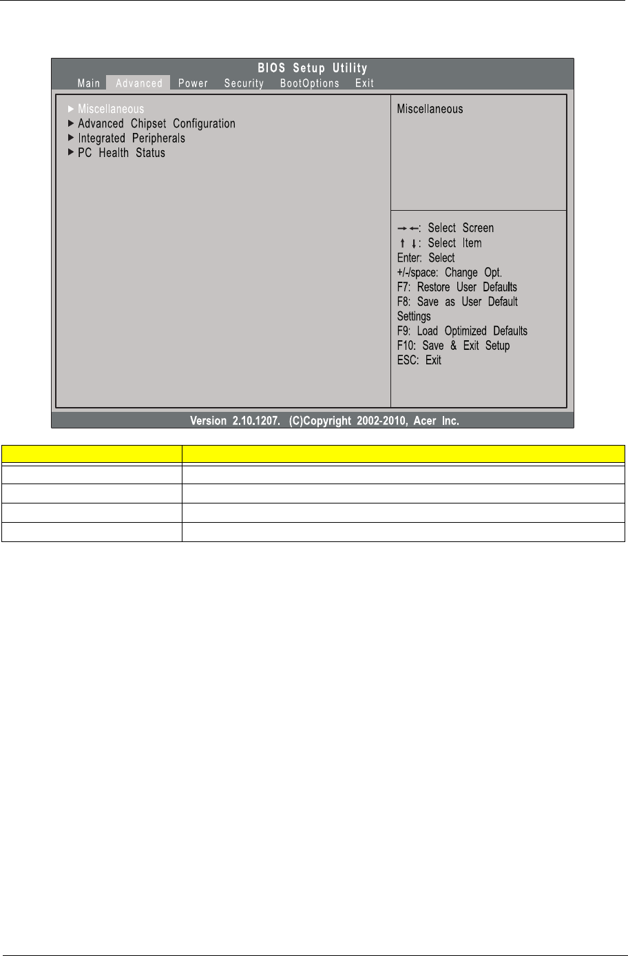
Advanced
Parameter Description
Miscellaneous Press Enter to access the Miscellaneous submenu
Advanced Chipset Configuration Press Enter to access the Advanced Chipset Configuration submenu
Integrated Peripherals Press Enter to access the Integrated Peripherals submenu
PC Health Status Press Enter to access the PC Health Status submenu
12 Chapter 2
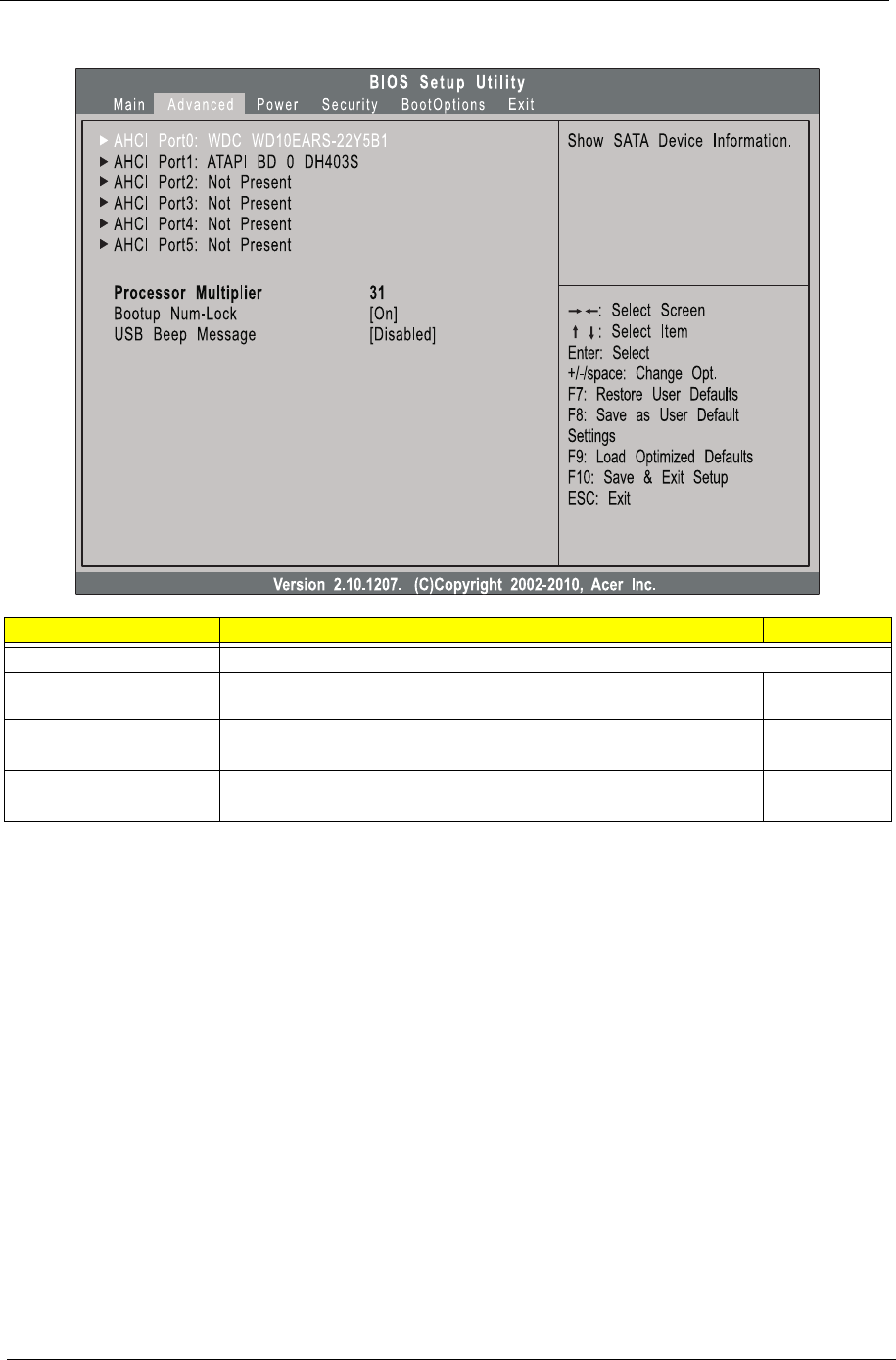
Miscellaneous
Parameter Description Option
AHCI Port0/1/2/3/4/5 Displays the status of auto detection of the AHCI device.
Processor Multiplier This field is only visible if an engineering processor installed. It is only
accessible when the EIST function is disabled.
Bootup Num-lock Selects power on state for Num Lock. On
Off
USB Beep Message Enables or disables BIOS to display error beeps or messages during USB
device enumeration.
Enabled
Disabled

Chapter 2 13
Advanced Chipset Configuration
Parameter Description Option
Intel EIST When enabled, this feature allows the OS to reduce power consumption.
When disabled, the system operates at maximum CPU speed.
Enabled
Disabled
Intel Turbo Boost Enables or disables Intel Turbo Boost Technology. Enabled
Disabled
Intel AES-NI Enables or disables Advanced Encryption Standard New Instructions
(AES-NI).
Enabled
Disabled
Intel XD Bit When enabled, the processor disables code execution when a worm attempts to
insert a code in the buffer preventing damage and worm propagation.
When disabled, the processor forces the Execute Disable (XD) Bit feature flag to
always return to 0.
Enabled
Disabled
Intel VT Enables or disables the Virtualization Technology (VT) availability. If enabled, a
virtual machine manager (VMM) can utilize the additional hardware virtualization
capabilities provided by this technology.
Note: A full reset is required to change the setting.
Enabled
Disabled
Video Memory Size Select the amout of system memory used by the Intel graphics device. 32MB
64 MB
128 MB
Disabled
DVMT Mode Select a video memory mode. DVMT
Fixed
DVMT/Fixed Memory
Size
Select a video memory size. 256MB
128 MB
Maximum
14 Chapter 2
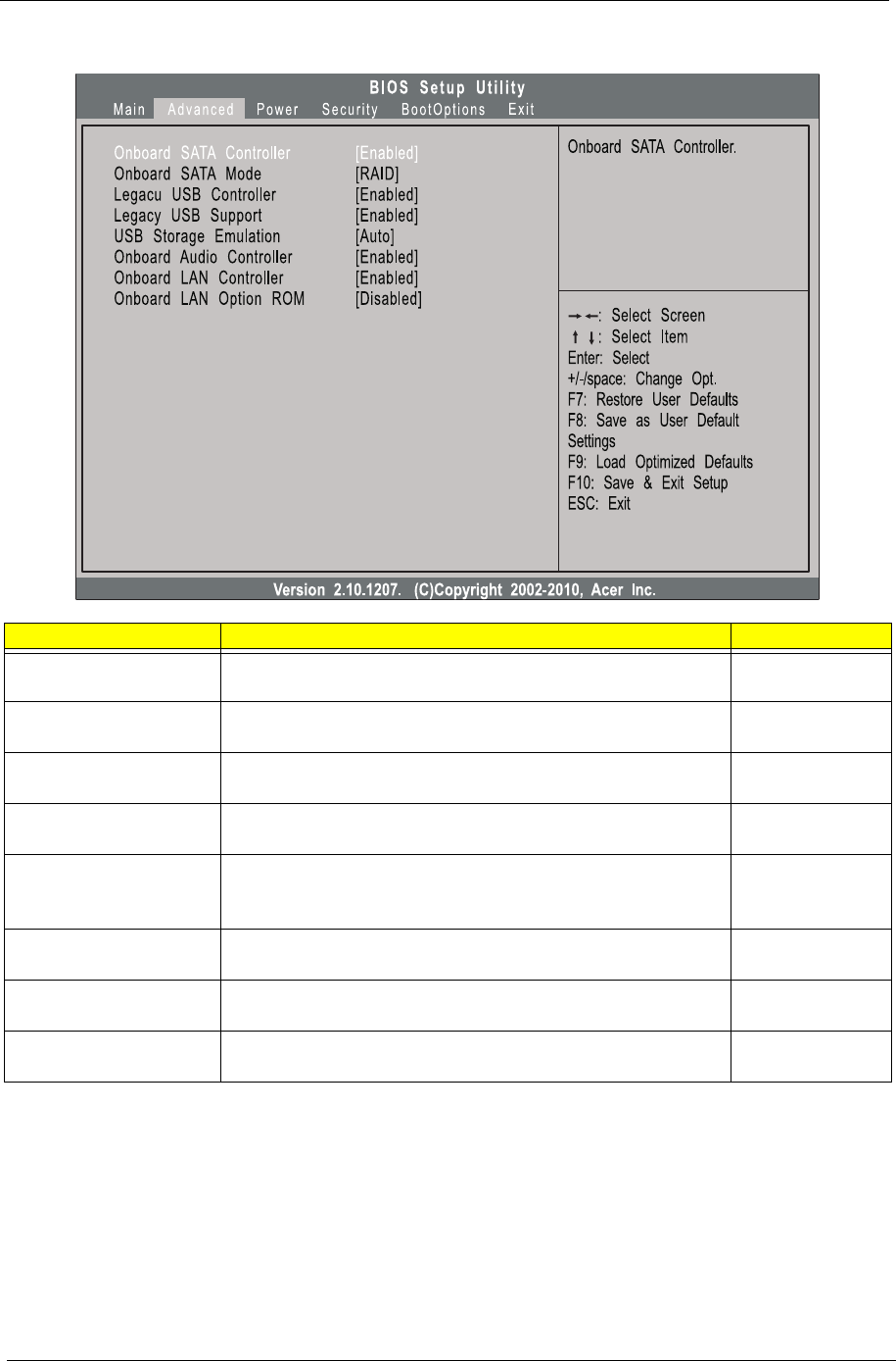
Integrated Peripherals
Parameter Description Option
Onboard SATA Controller Enables or disables the onboard SATA controller. Enabled
Disabled
Onboard SATA Mode Select an operating mode for the onboard SATA. AHCI
Native IDE
Legacy USB Controller Enables or disables support for legacy USB devices Enabled
Disabled
Legacy USB Support Enables or disables support for legacy USB devices. Enabled
Disabled
USB Storage Emulation Select emulation type for a USB mass storage device. Auto
Floppy
Hard Disk
Onboard Audio Controller Enables or disables the onboard audio controller. Enabled
Disabled
Onboard LAN Controller Enables or disables the onboard LAN controller. Enabled
Disabled
Onboard LAN Option ROM Enables or disables the load of embedded option ROM for onboard
network controller.
Enabled
Disabled
Chapter 2 15
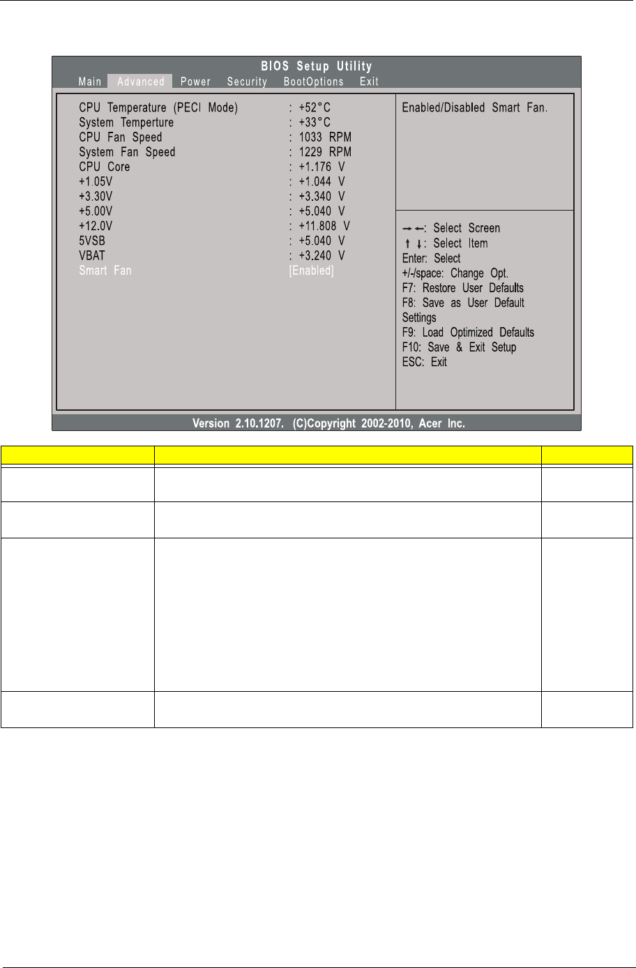
PC Health Status
Parameter Description Option
CPU Temperature (PECI
Mode)
Set the shutdown temperature of the CPU. 0°C
Disabled
System Temperature Set the shutdown temperature of the system. 0°C
Disabled
CPU Fan Speed
System Fan Speed
CPU Core
+1.05V
+3.30V
+5.00V
+12.0V
5VSB
VBAT
These items let you monitor the parameters for critical voltages and fan
speeds.
Smart Fan Enables or disables the smart system fan control function. Enabled
Disabled
16 Chapter 2
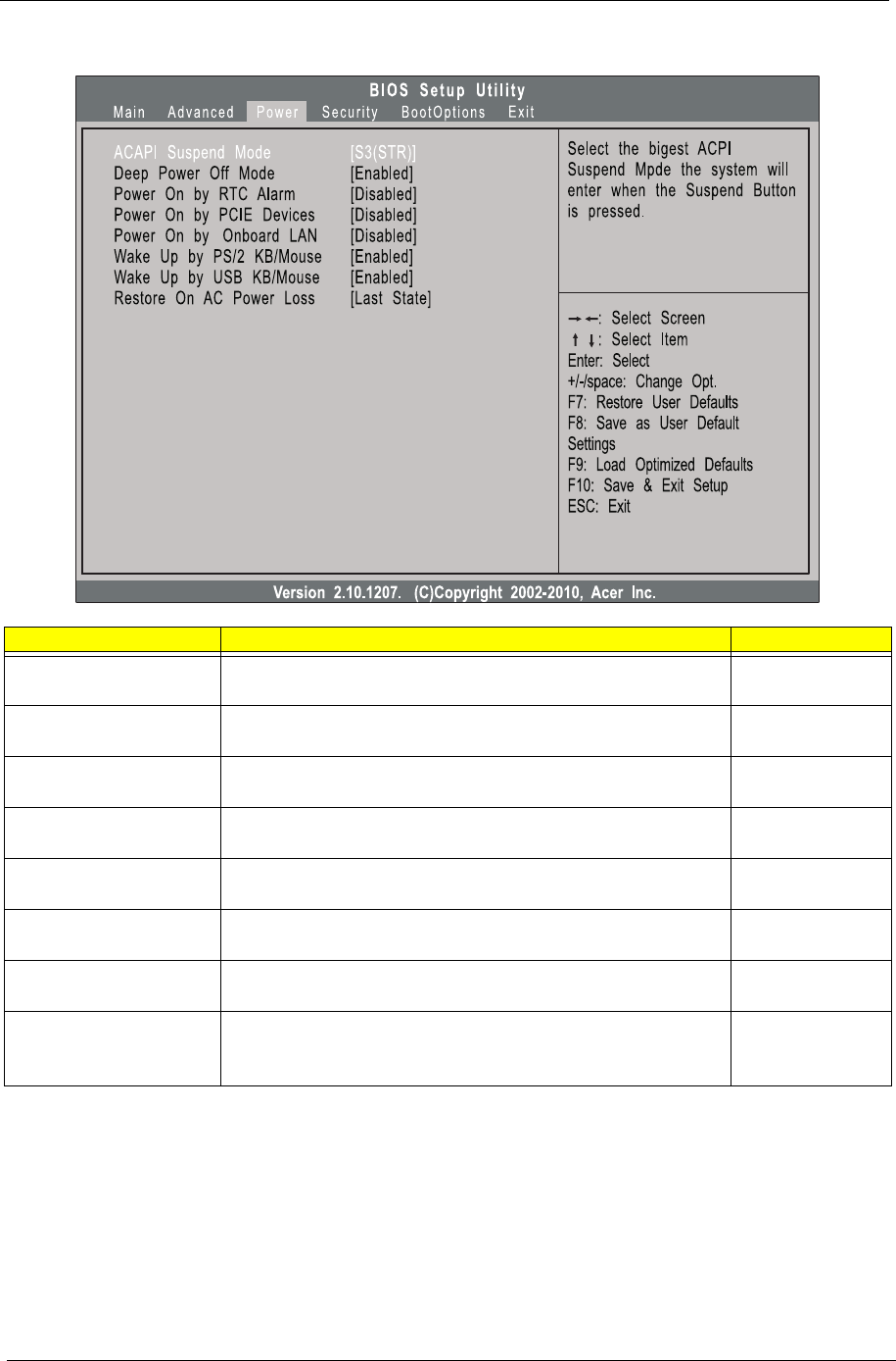
Power
Parameter Description Option
ACPI Suspend Mode Select an ACPI state. S3 (STR)
S1 (POS)
Deep Power Off Mode Enables or disables the deep power off mode. Enabled
Disabled
Power On by RTC Alarm Enables or disables real time clock (RTC) to generate a wake event. Enabled
Disabled
Power On by PCIE Devices Enables or disables to wake up the system from a power saving mode
through an event on a PCI Express device.
Enabled
Disabled
Power On by Onboard LAN Enables or disables an onboard LAN controller to generate a wake
event.
Enabled
Disabled
Wake Up by PS/2 KB/Mouse Enables or disables to wake up the system from a power saving mode
using a PS2 keyboard or mouse.
Enabled
Disabled
Wake Up by USB KB/Mouse Enables or disables to wake up the system from a power saving mode
using a USB keyboard or mouse.
Enabled
Disabled
Restore On AC Power Loss Enables or disables the system to reboot after a power failure or
interrupt occurs.
Power Off
Power On
Last State
Chapter 2 17
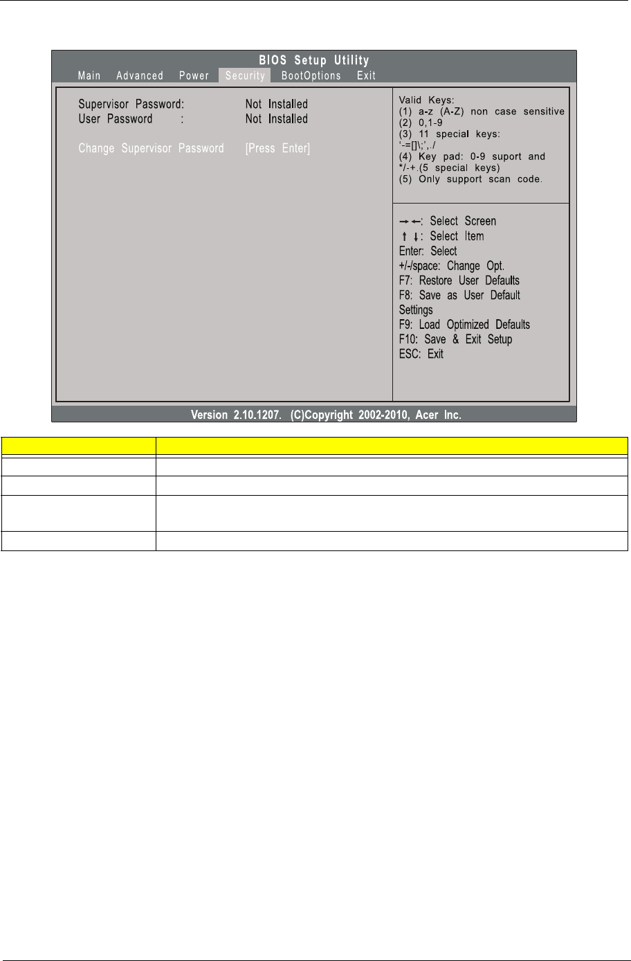
Security
Setting a system password
1. Use the up/down arrow keys to select a password parameter (Change Supervisor Password or Change
User Password) menu then press Enter.
A password box will appear.
2. Type a password then press Enter.
The password may consist up to six alphanumeric characters (A-Z, a-z, 0-9)
3. Retype the password to verify the first entry then press Enter again.
4. Press F10.
5. Select Yes to save the new password and close the Setup Utility.
Changing the system password
1. Use the up/down arrow keys to select password parameter (Change Supervisor Password or Change
User Password) menu then press Enter.
2. Type the original password then press Enter.
3. Type a new password then press Enter.
4. Retype the password to verify the first entry then press Enter again.
5. Press F10.
6. Select Yes to save the new password and close the Setup Utility.
Removing a system password
Parameter Description
Supervisor Password Indicates the status of the supervisor password.
User Password Indicates the status of the user password.
Change Supervisor
Password
Supervisor password prevents unauthorized access to the BIOS Setup Utility.
Press Enter to change the Supervisor password.
Change User Password Press Enter to change the User password.
18 Chapter 2
1. Use the up/down arrow keys to select password parameter (Change Supervisor Password or Change
User Password) menu then press Enter.
2. Enter the current password then press Enter.
3. Press Enter twice without entering anything in the password fields.
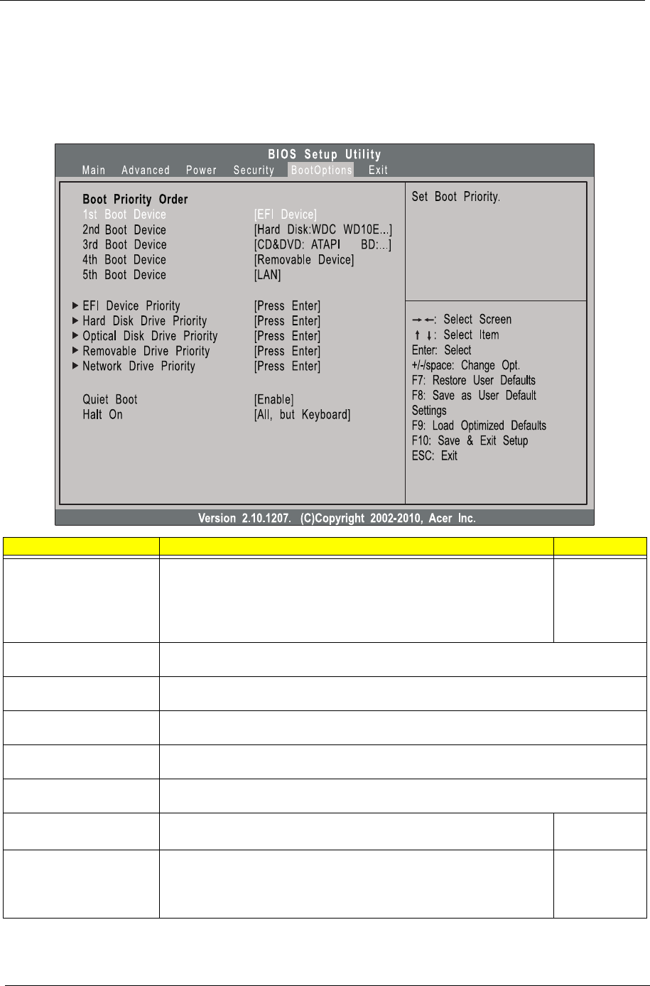
Boot Options
Parameter Description Option
1st/2nd/3rd/4th/5th Boot
Device
Specifies the boot order from the available devices. Hard Disk
CD/DVD
Removable
Device
LAN
EFI Device Priority Press Enter to access the EFI Device Priority submenu and specify the boot device priority
sequence from available EFI devices.
Hard Disk Drive Priority Press Enter to access the Hard Disk Drive Priority submenu and specify the boot device
priority sequence from available hard drives.
Optical Disk Drive Priority Press Enter to access the Optical Disk Drive Priority submenu and specify the boot device
priority sequence from available CD/DVD drives.
Removable Device Priority Press Enter to access the Removable Device Priority submenu and specify the boot device
priority sequence from available removable drives.
Network Device Priority Press Enter to access the Network Device Priority submenu and specify the boot sequence
from available network devices.
Quiet Boot When enabled, the BIOS splash screen displays during startup.
When disabled, the diagnostic screen displays during startup.
Enabled
Disabled
Halt On Determines whether the system will stop for an error during the POST. All, but
keyboard
No Errors
All Errors
Chapter 2 19
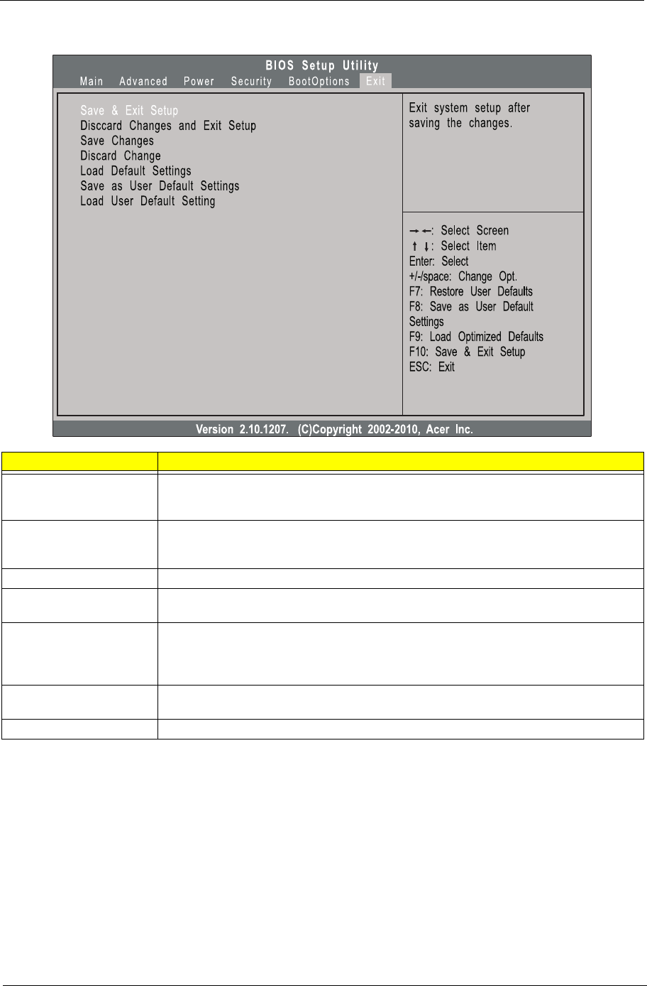
Exit
Parameter Description
Save & Exit Setup When you have completed the system configuration changes, select this option to leave the
BIOS Setup Utility and reboot the computer, so the new system configuration parameters can
take effect. Select Save & Exit Setup from the Exit menu and press Enter.
Discard Changes and Exit
Setup
Select this option to quit the BIOS Setup Utility without making any permanent changes to the
system configuration, and reboot the computer. Select Discard Changes and Exit Setup from
the Exit menu and press Enter.
Save Changes Select this option and press Enter to save all the changes and return to the BIOS Setup Utility.
Discard Change Select this option and press Enter to discard all the changes and return to the BIOS Setup
Utility.
Load Default Settings To set this feature, select Load Default Settings from the Exit menu and press Enter. Then,
select OK to allow the BIOS to automatically load optimal defaults to the BIOS settings. The
Optimal settings are designed for maximum system performance, but may not work best for all
computer applications.
Save as User Default
Settings
Select this option and press Enter to save changes that you have made as user defaults.
Load User Default Settings Select this option and press Enter to restore user defaults.

20 Chapter 2

Chapter 3 21
This chapter contains step-by-step procedures on how to disassemble the desktop computer for maintenance
and troubleshooting.
Disassembly Requirements
To disassemble the computer, you need the following tools:
•Wrist grounding strap and conductive mat for preventing electrostatic discharge
•Flat-blade screwdriver
•Philips screwdriver
•Hex screwdriver
•Plastic flat-blade screwdriver
•Plastic tweezers
NOTE: The screws for the different components vary in size. During the disassembly process, group the
screws with the corresponding components to avoid mismatch when putting back the components.
Pre-disassembly Procedure
Before proceeding with the disassembly procedure, perform the steps listed below:
1. Turn off the system and all the peripherals connected to it.
2. Unplug the power cord from the power outlets.
3. Unplug the power cord from the system.
4. Unplug all peripheral cables from the system.
5. Place the system unit on a flat, stable surface.
Chapter 3
System Disassembly
22 Chapter 3
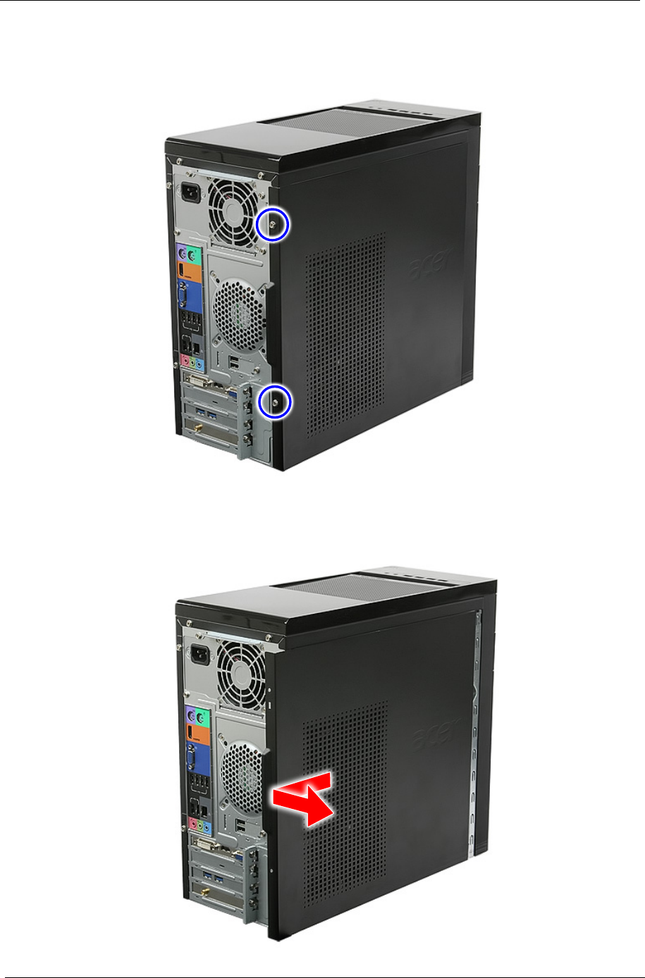
Removing the Side Panel
1. Remove the two screws located on the rear edge of the side panel.
2. Slide the side panel toward the back of the chassis until the tabs on the cover disengage with the slots on
the chassis, then lift the side panel away from the server and put it aside for reinstallation later.
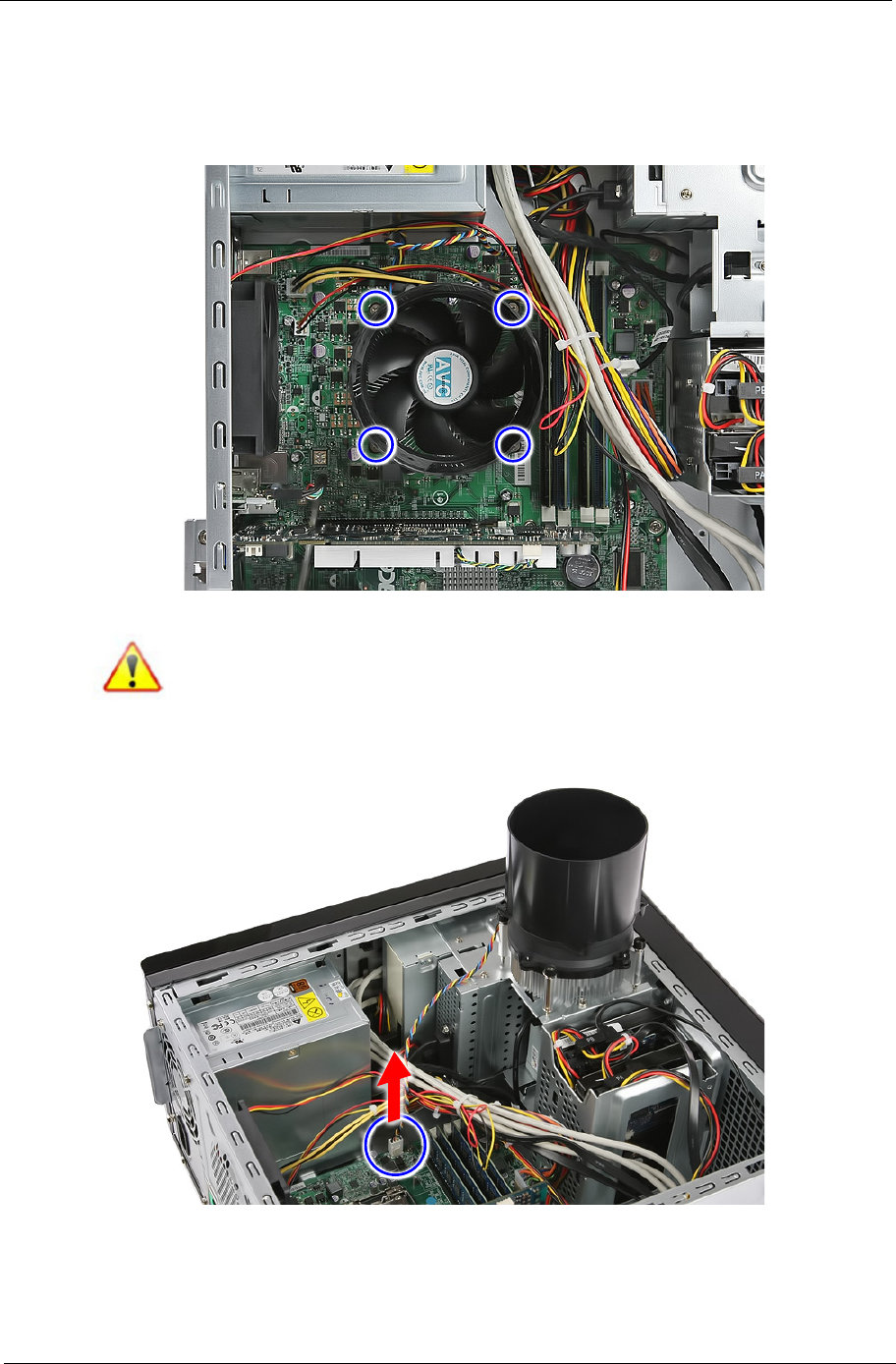
Chapter 3 23
Removing the Heatsink Fan Assembly
WARNING:The heatsink becomes very hot when the system is on. NEVER touch the heatsink with any metal
or with your hands.
1. Use a screwdriver to loosen the four screws on the heatsink.
Note: Plastic parts containing bromide have been highlighted with the yellow circle as the
above image shows. Please remove these parts and follow local regulations for disposal.
2. Disconnect the heatsink fan cable from the mainboard.
3. Remove the heatsink fan assembly from the chassis then lay it down in an upright position—with the
thermal patch facing upward. Do not let the thermal patch on the heatsink fan assembly touch the work
surface.
4. Use an alcohol pad to wipe off the thermal grease from both the heatsink and the processor.

24 Chapter 3
Removing the Processor
IMPORTANT:Before removing a processor from the mainboard, make sure to create a backup file of all
important data.
WARNING:The processor becomes very hot when the system is on. Allow it to cool off first before handling.
1. Release the load lever.
2. Pull the load lever to the fully open, upright position and lift the load plate.
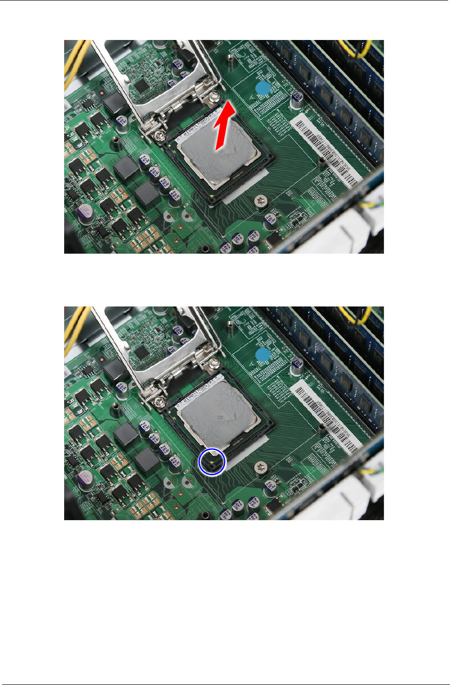
Chapter 3 25
3. Pull out the processor from the socket.
IMPORTANT: If you are going to install a new processor, note the arrow on the corner to make sure the
processor is properly oriented over the socket.
26 Chapter 3
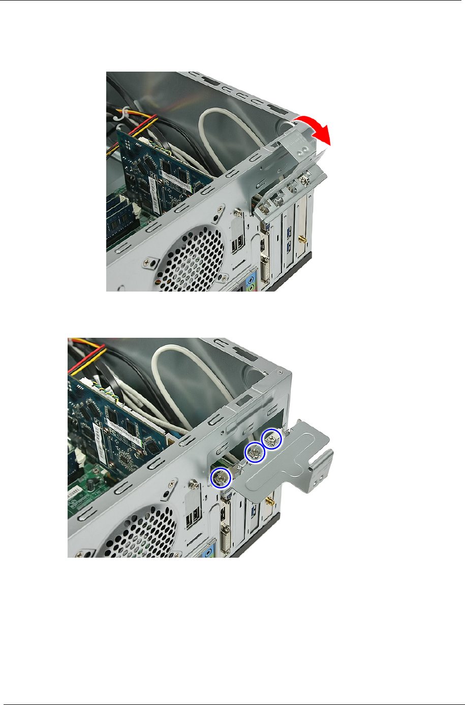
Removing the VGA Card
1. Release the PCI latch by pulling the tab in the direction shown.
2. Remove the three screws that secure the cards to the chassis.
Chapter 3 27
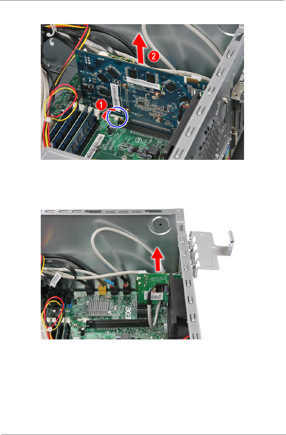
3. Use a finger to press the release clip and gently pull up the card to remove it from the mainboard.
Removing the Mode Card
1. Gently pull up the Mode card to remove it from the mainboard.
28 Chapter 3
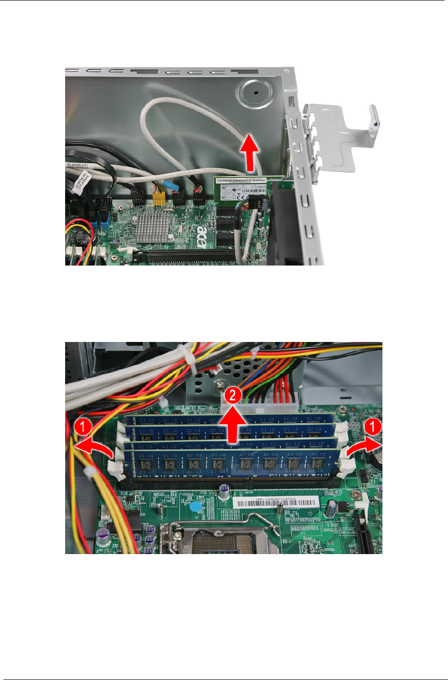
Removing the TV Card
1. Gently pull up the TV card to remove it from the mainboard.
Removing the Memory Modules
1. Release the DIMM module by pressing the holding clips (1) on both sides of the DIMM slot. Gently lift the
DIMM module (2) to remove it from the slot.
2. Repeat step 1 until you have removed all DIMM modules from their slots.
Chapter 3 29
Removing the Hard Disk Drive
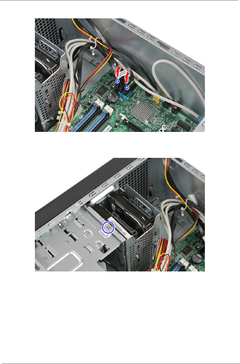
1. Disconnect the data and power cables from the rear of the hard drive.
2. Open the cable retention clip.
30 Chapter 3
3. Disconnect the data cables from the mainboard.
4. Remove the HDD bracket
a. Remove the screw that secures the HDD bracket to the chassis.
Chapter 3 31
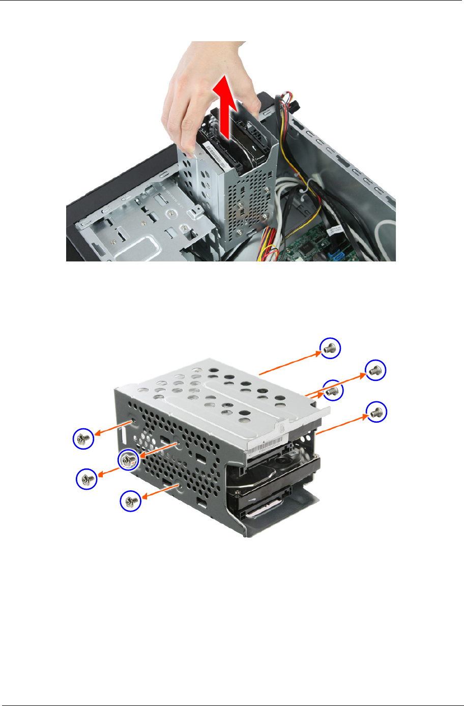
b. Lift the bracket up and turn it over.
5. Remove the HDD modules.
a. Remove the eight screws that secure the HDD module to the HDD bracket.
32 Chapter 3
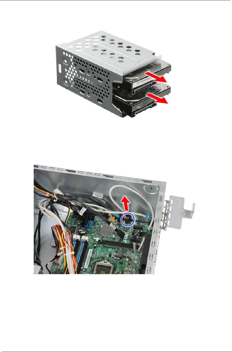
b. Slide the HDD out of the bracket.
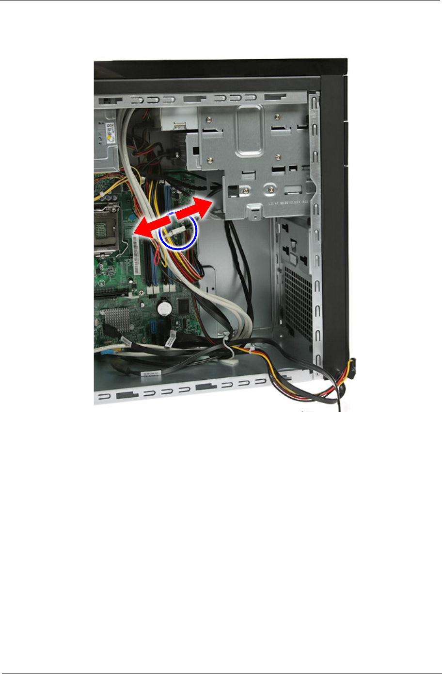
Removing the USB Board
1. Disconnect the USB cable from its mainboard connector.
Chapter 3 33
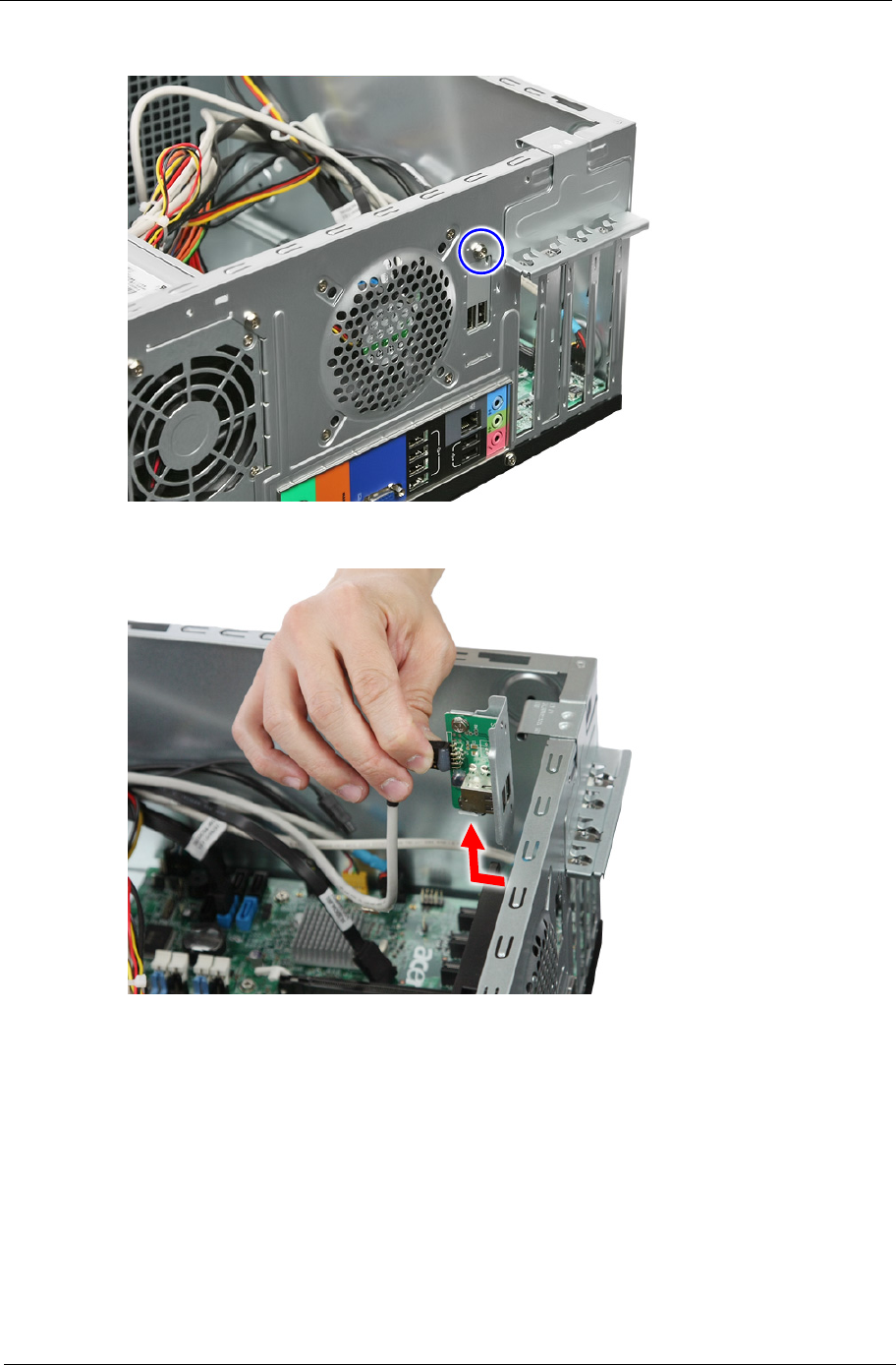
2. Remove the screw that secures the USB board bracket to the chassis.
3. Pull up the USB board and remove from the chassis.
34 Chapter 3
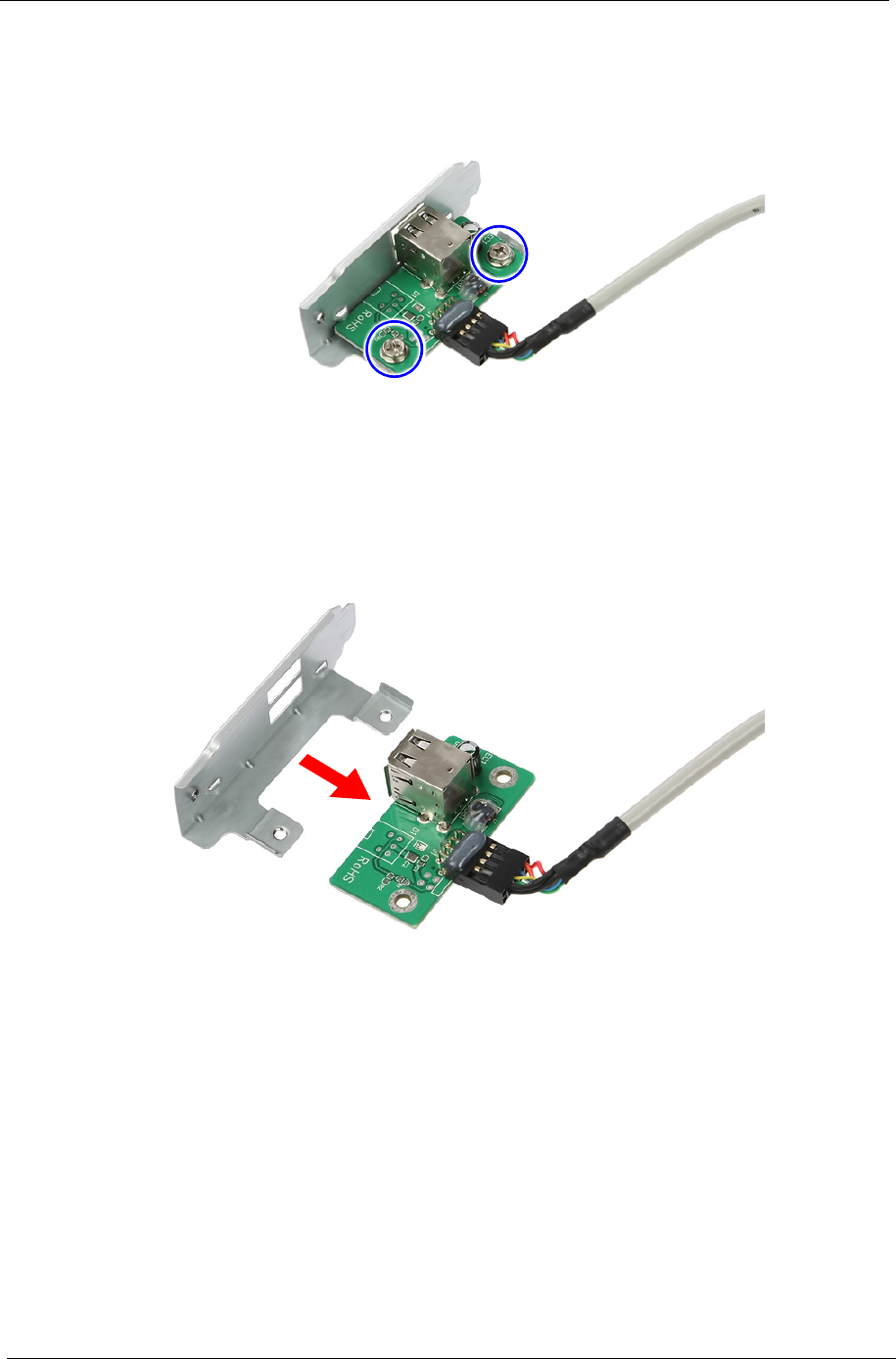
4. Remove the two screws securing the USB board to the bracket.
5. Remove the USB board from its bracket.
Chapter 3 35
Removing the Front Bezel
1. Disconnect the LED cable.
36 Chapter 3
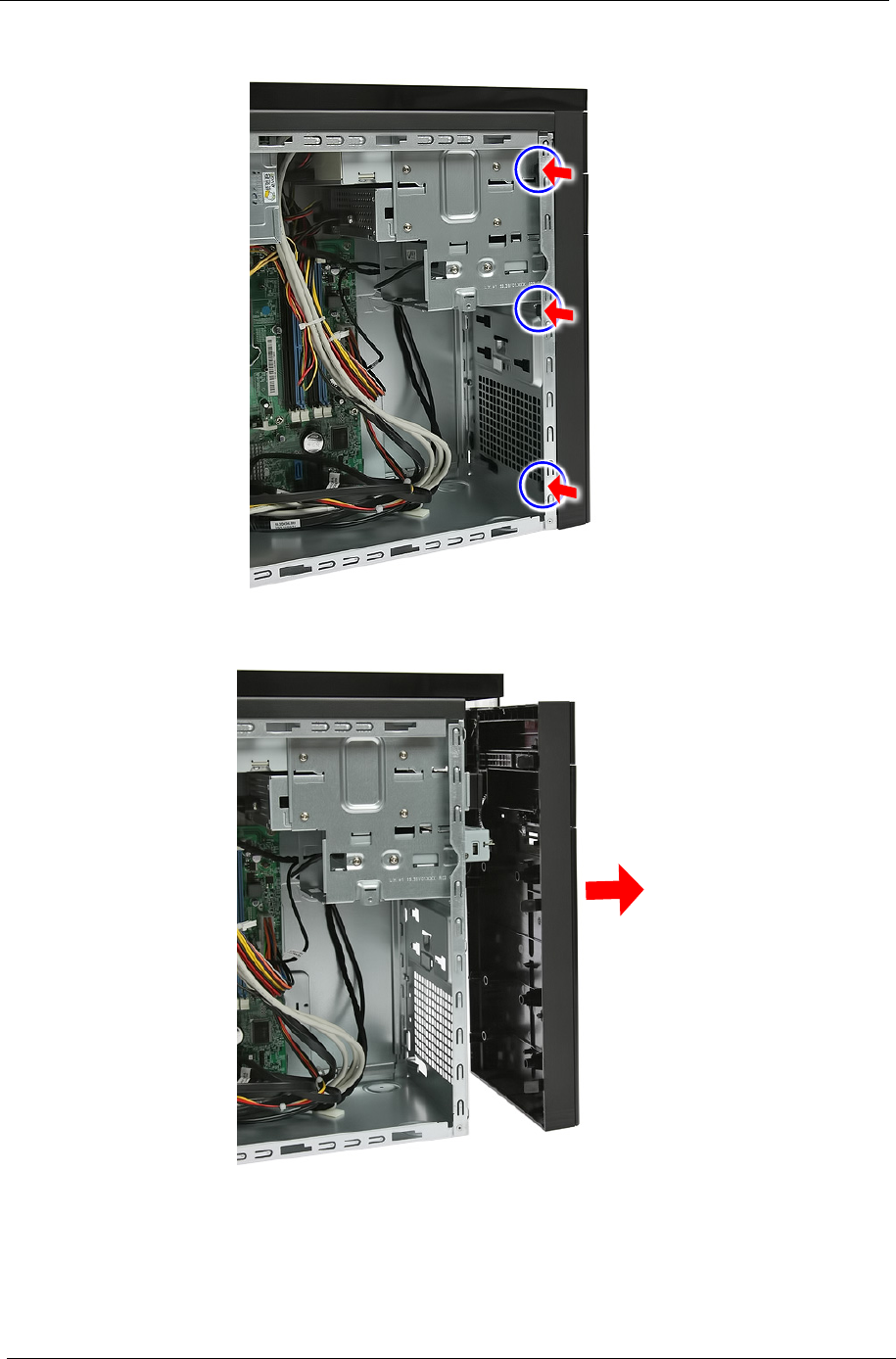
2. Release the front bezel retention tabs from the chassis interior.
3. Pull the bezel away from the chassis.
Chapter 3 37
Removing the Optical Drive
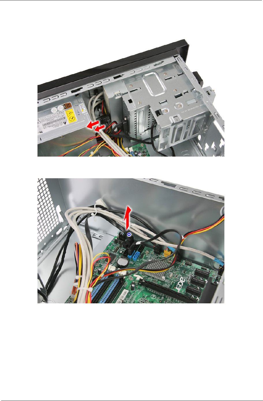
1. Disconnect the data and power cables from the rear of the optical drive.
2. Disconnect the other end of the data cable from the mainboard.
38 Chapter 3
3. Remove the two screws securing the optical drive.
4. Pull out the optical drive from the drive bay.

Chapter 3 39
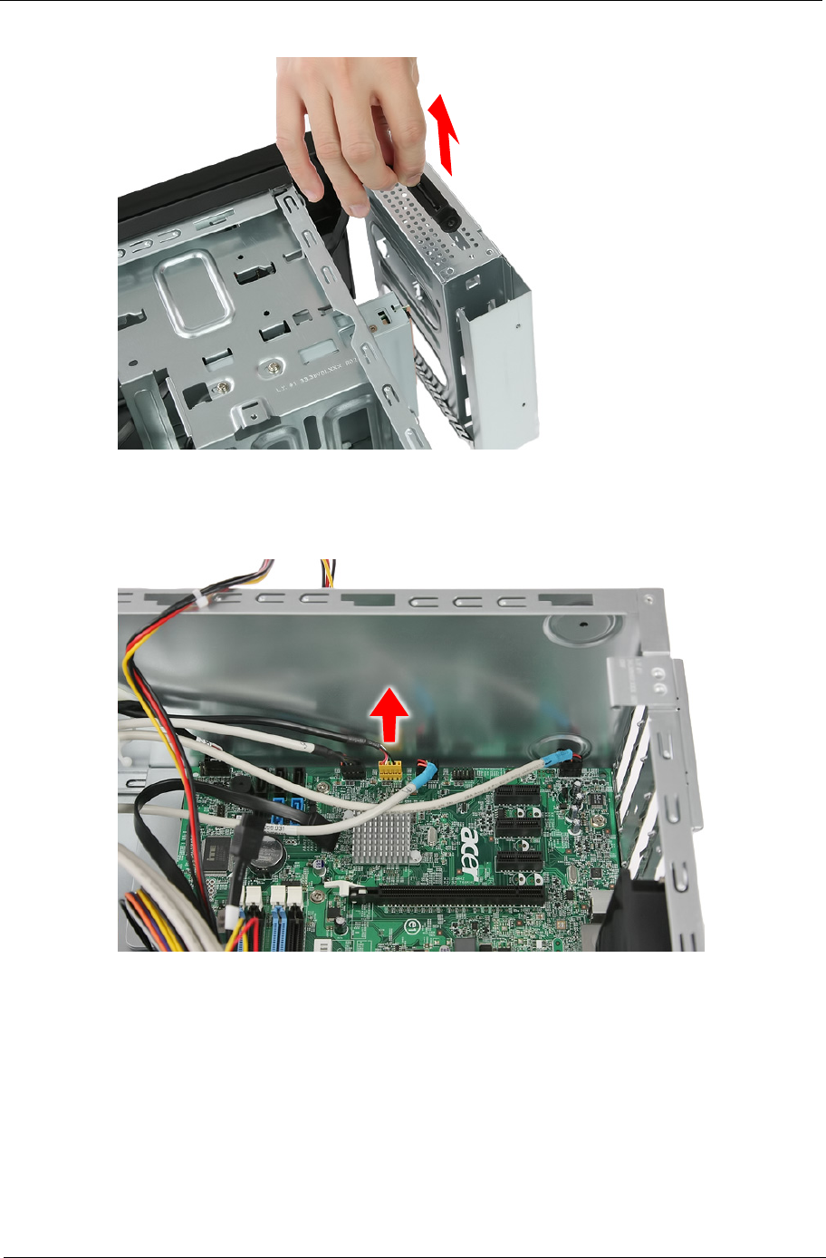
Removing the Removable HDD
1. Gently slide the HDD carrier latch to the right to open the carrier door.
2. Slide the removable HDD carrier out of the HDD bracket.
40 Chapter 3
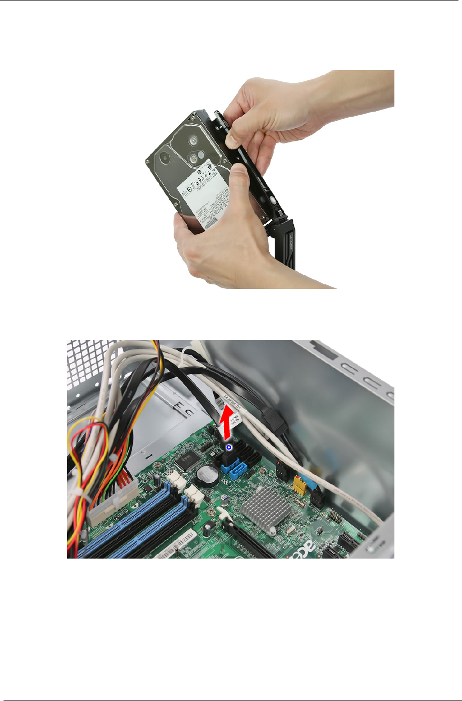
3. Remove the HDD module.
a. Pry open one side of the removable HDD carrier until the hooks are away from the screw bores.
Remove HDD module.
4. Remove the removable HDD bracket.
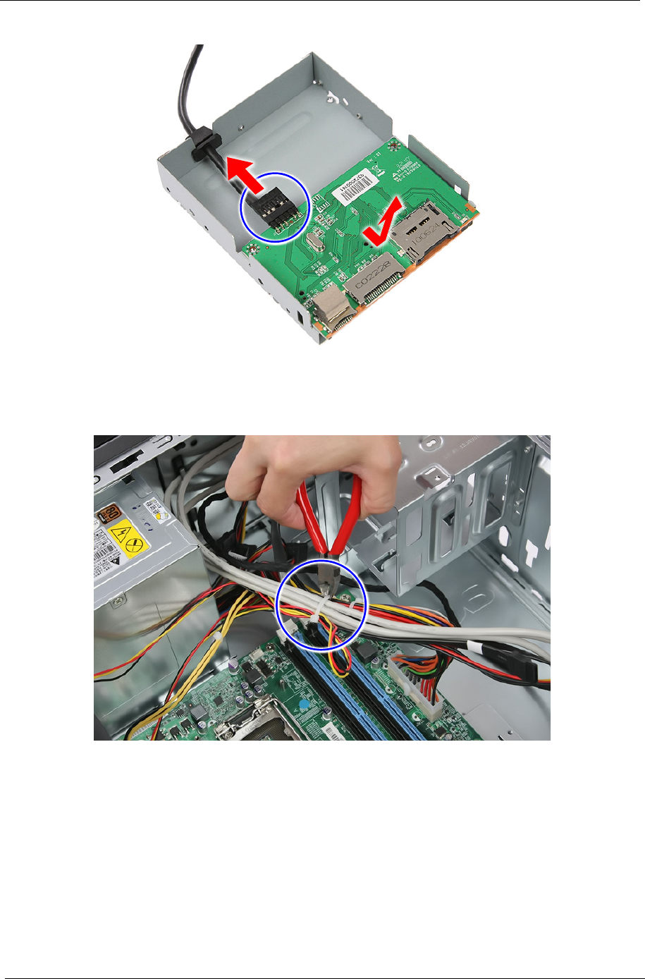
a. Disconnect the data cable from the mainboard.
Chapter 3 41
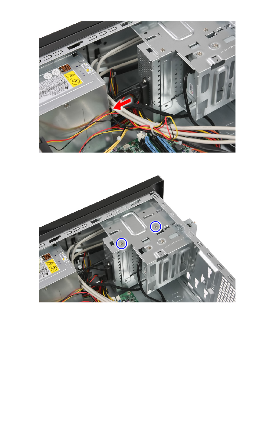
b. Disconnect the power cable.
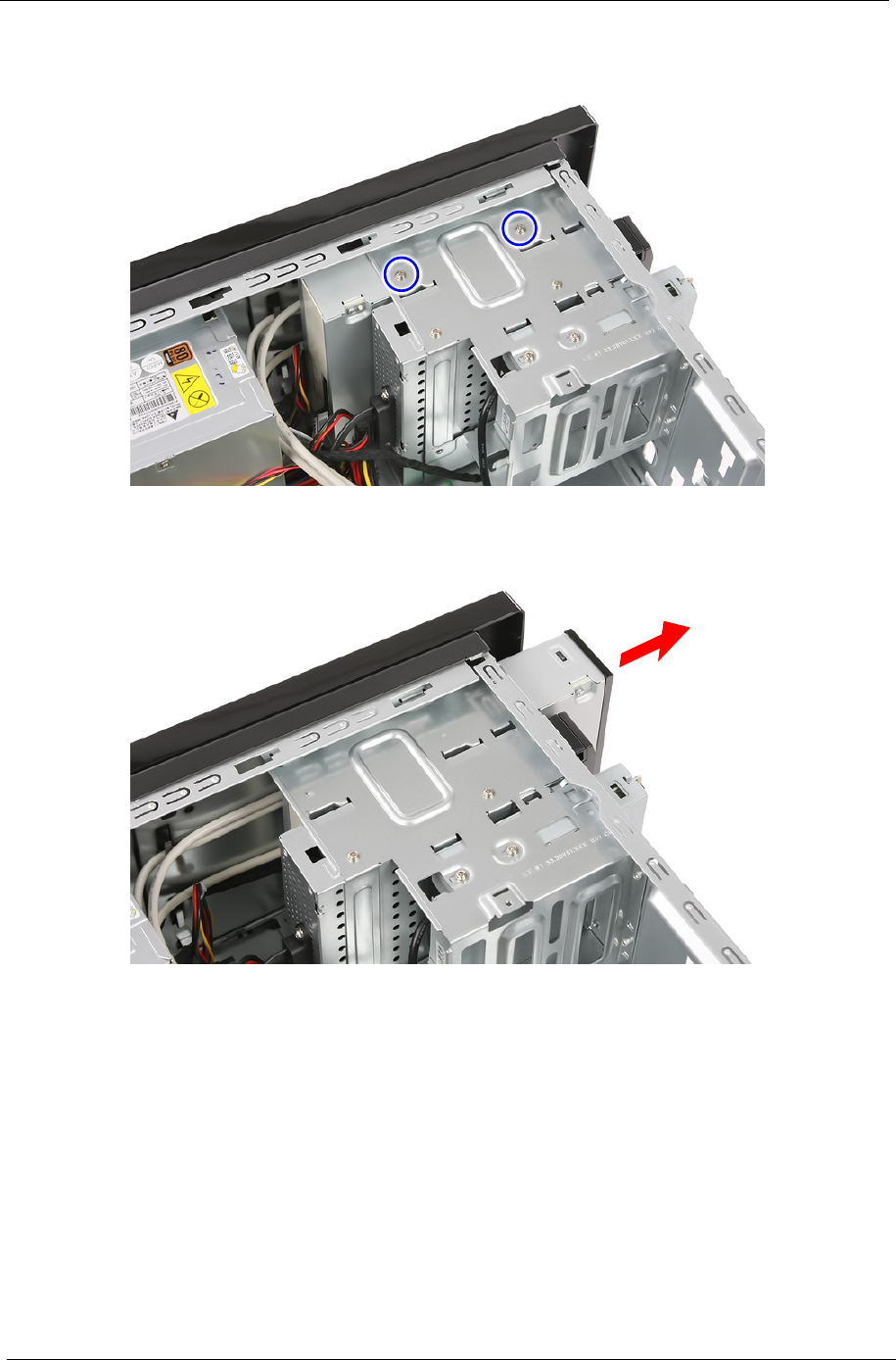
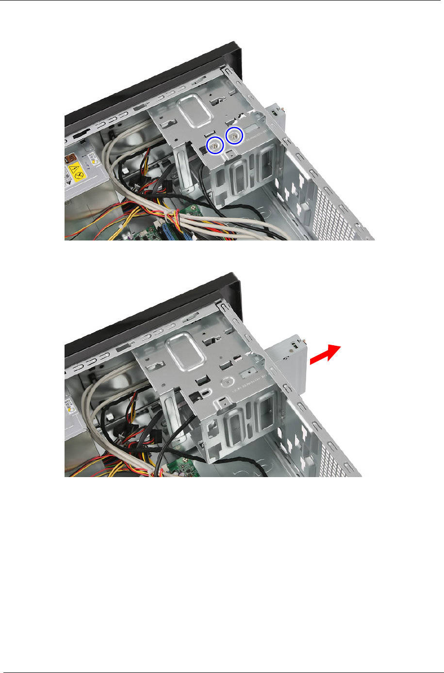
c. Remove the two screws secruing the removable HDD bracket to the chassis.
42 Chapter 3
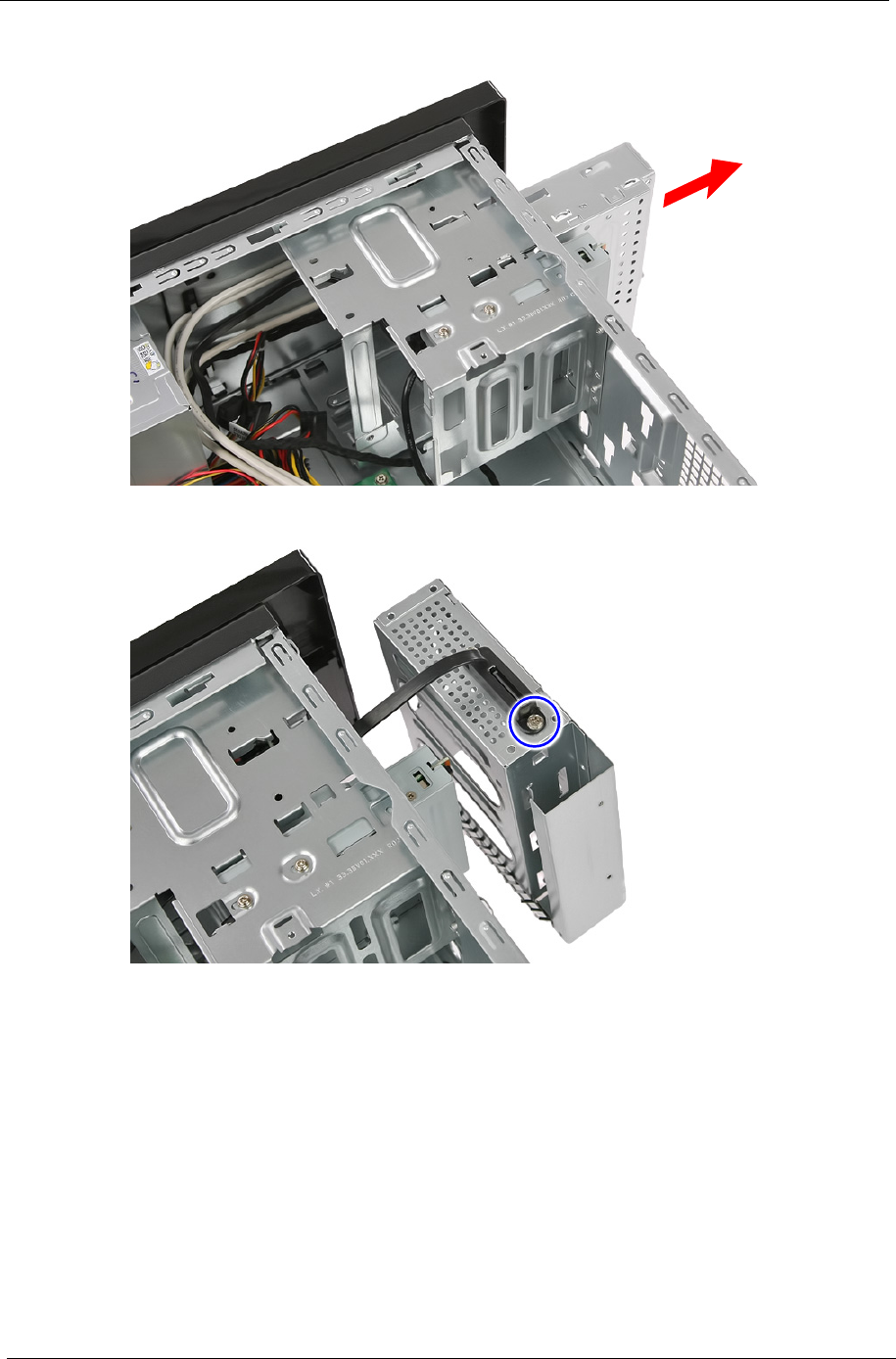
d. Slide the removable HDD bracket out of the chassis. .
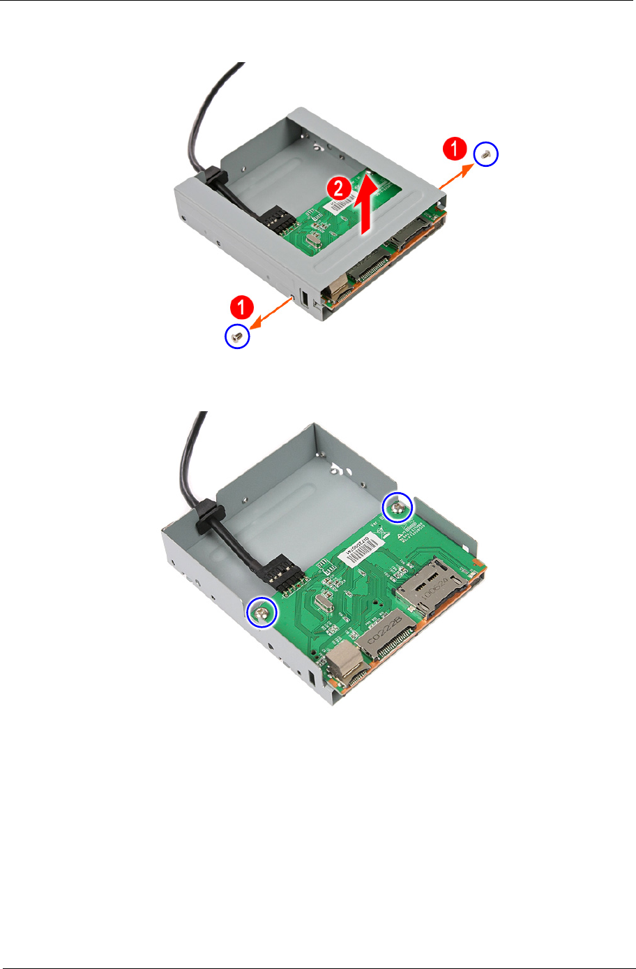
e. Remove the screw securing the cable to the HDD bracket.
Chapter 3 43
f. Remove the cable from the bracket.
Removing the Card Reader
1. Disconnect the card reader cable from its mainboard connector.
44 Chapter 3
2. Remove the two screws securing the card reader bracket to the chassis.
3. Pull the card reader bracket out of chassis.
4. Removing the card reader board.
Chapter 3 45
a. Remove the two screws (1) securing the card reader to the bracket. Remove the top part of the
bracket (2).
b. Remove the two screws securing the card reader board to the lower part of the bracket.
46 Chapter 3
c. Disconnect the cable from the card reader board and remove the card reader board from the bracket.
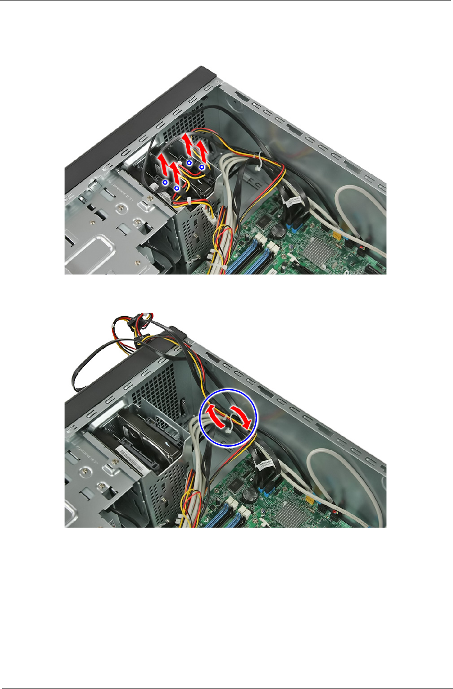
Removing the Power Supply
1. Cut the cable retention strip.
NOTE: Make sure you have spare cable retention clips handy, so that you can bundle the cables after
replacing the power supply.
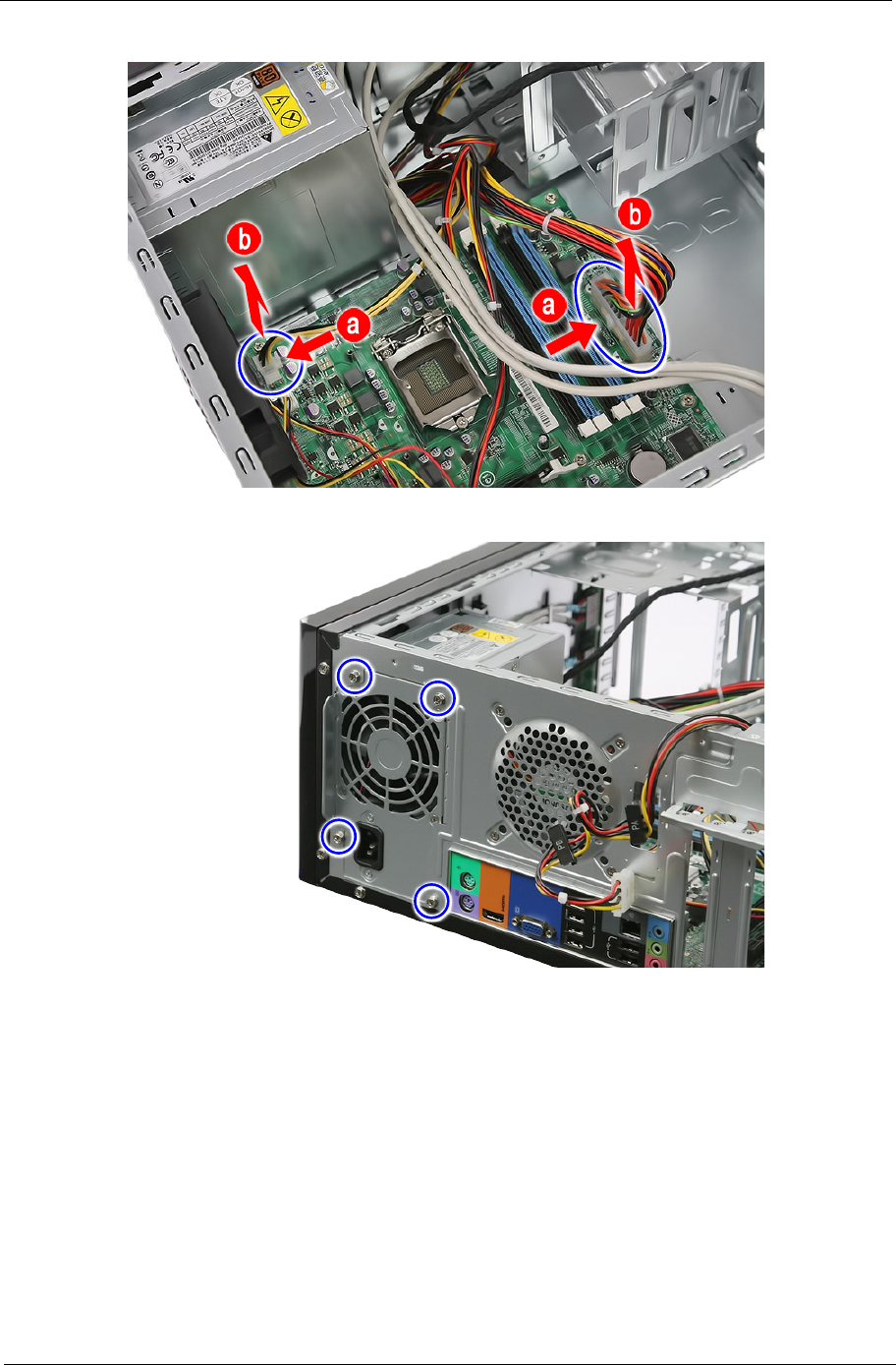
Chapter 3 47
2. Disconnect the 24-pin and 4-pin power supply cables from the mainboard.
3. Remove the four screw that secures the power supply to the chassis.
48 Chapter 3
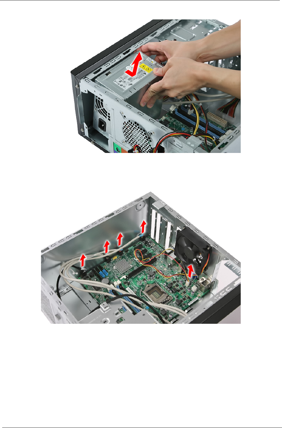
4. Lift the power supply module out of the chassis.
Removing the Mainboard
1. Disconnect the remaining cables from the mainboard.
Chapter 3 49
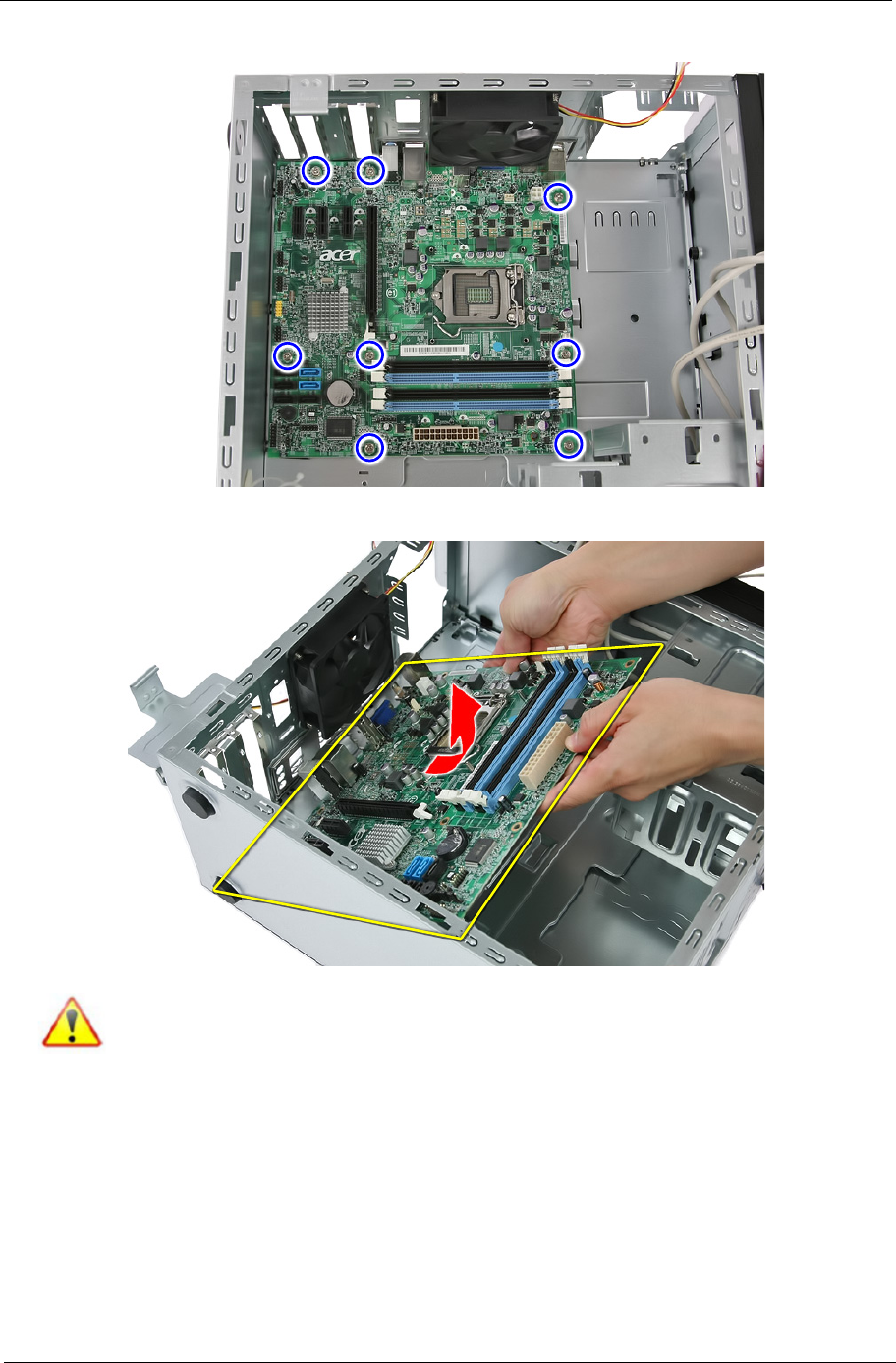
2. Remove the eight screws securing the mainboard to the chassis.
3. Lift the mainboard from the chassis.
Note: Circuit boards >10 cm² has been highlighted with the yellow rectangle as above image
shows. Please detach the circuit boards and follow local regulations for disposal.
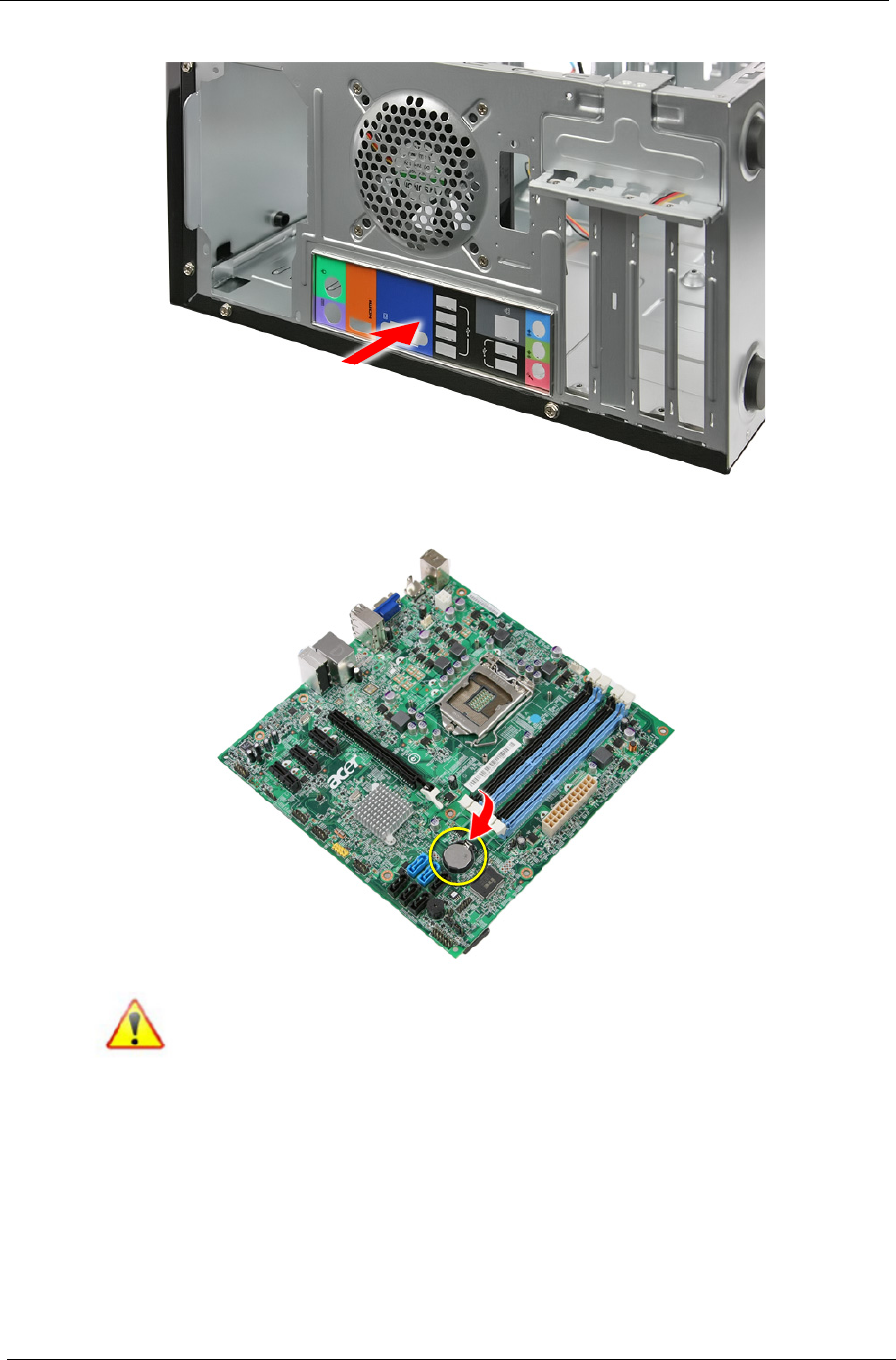
50 Chapter 3
4. Press the I/O shield to remove it.
5. Remove the RTC battery.
Note: RTC battery has been highlighted with the yellow circle as above image shows.
Please remove the RTC battery and follow local regulations for disposal.

Chapter 4 51
This chapter provides instructions on how to troubleshoot system hardware problems.
Hardware Diagnostic Procedure
IMPORTANT:The diagnostic tests described in this chapter are only intended to test Acer products. Non-Acer
products, prototype cards, or modified options can give false errors and invalid system
responses.
1. Obtain the failing symptoms in as much detail as possible.
2. Verify the symptoms by attempting to recreate the failure by running the diagnostic tests or repeating the
same operation.
3. Refer to “Power System check” and “Beep Codes” to determine which corrective action to perform.
System Troubleshooting
Chapter 4

52 Chapter 4
System Check Procedures
Power System Check
If the system will power on, skip this section. Refer to System External Inspection.
If the system will not power on, do the following:
•Check if the power cable is properly connected to the system and AC source.
•Check if the voltage selector switchis set to the correct voltage setting.
System External Inspection
1. Inspect the LED indicators on the front panel, which can indicate the malfunction.
2. Make sure that air flow is not blocked.
3. Make sure nothing in the system is making contact that could short out power.
4. If the problem is not evident, continue with System Internal Inspection.
System Internal Inspection
1. Turn off the system and all the peripherals connected to it.
2. Unplug the power cord from the power outlets.
3. Unplug the power cord from the system.
4. Unplug all peripheral cables from the system.
5. Place the system unit on a flat, stable surface.
6. Remove the system covers.For instructions on removing system covers, refer to “System Disassembly”.
7. Verify that components are properly seated.
8. Verify that all cable connectors inside the system are firmly and correctly attached to their appropriate
connectors.
9. Verify that all components are Acer-qualified and supported.
10. Replace the system covers.
11. Power on the system.
12. If the problem with the system is not evident, you can try viewing the POST messages and BIOS event
logs during the system startup.
Chapter 4 53
Beep Codes
Beep codes are used by the BIOS to indicate a serious or fatal error to the end user. Beep codes are used
when an error occurs before the system video has been initialized. Beep codes will be generated by the
system board speaker, commonly referred to as the PC speaker.
AMIBIOS displays the checkpoints in the bottom right corner of the screen during POST. This display method
is limited, since it only displays checkpoints that occur after the video card has been activated.
Not all computers using AMIBIOS enable this feature. In most cases, a checkpoint card is the best tool for
viewing AMIBIOS checkpoints.
Beep Symptom Cause and Description
One short beep System is ready.
System is OK.
Continuous one long beep Memory not installed or memory error.
One long beep and two short beeps then
repeat.
VGA not installed or VGA error.
Graphics card error/not installed, graphics card memory
error or graphics card BIOS checksum error.
One long beep then one short beep BIOS damaged.
BIOS is damaged, BIOS POST jumps to Boot Block to
execute the default procedures.
Two short beeps CMOS damaged.
CMOS checksum error or CMOS battery loss occurs.

54 Chapter 4
Checkpoints
A checkpoint is either a byte or word value output to I/O port 80h.The BIOS outputs checkpoints throughout
bootblock and Power-On Self Test (POST) to indicate the task the system is currently executing. Checkpoint
sare very useful in aiding software developers or technicians in debugging problems that occur during the pre-
boot process.
Viewing BIOS checkpoints
Viewing all checkpoints generated by the BIOS requires acheckpoint card, also referred to as a POST card or
POST diagnostic card. These are ISA or PCI add-in cards that show the value of I/O port 80h on a LED
display. Checkpoints may appear on the bottom right corner of the screen during POST. This display method
islimited, since it only displays checkpoints thatoccur after the video card has been activated.
Bootblock Initialization Code Checkpoints
The Bootblock initialization code sets up the chipset,memory, and other components before system memory is
available. The following table describes the type of checkpoints that may occur during the bootblock
initialization portion of the BIOS.
NOTE: Please note that checkpoints may differ between different platforms based on system
configuration.Checkpoints may change due to vendor requirements,system chipset or option ROMs
from add-in PCI devices.
Checkpoint Description
Before D0 If boot block debugger is enabled, CPU cache-as-RAM functionality is enabled at this point.
Stack will be enabled from this point.
D0 Early Boot Strap Processor (BSP) initialization like microcode update, frequency and other
CPU critical initialization. Early chipset initialization is done.
D1 Early super I/O initialization is done including RTC and keyboard controller. Serial port is
enabled at this point if needed for debugging. NMI is disabled. Perform keyboard controller
BAT test. Save power-on CPUID value in scratch CMOS. Go to flat mode with 4GB limit and
GA20 enabled.
D2 Verify the boot block checksum. System will hang here if checksum is bad.
D3 Disable CACHE before memory detection. Execute full memory sizing module. If memory
sizing module not executed, start memory refresh and do memory sizing in Boot block code.
Do additional chipset initialization. Re-enable CACHE. Verify that flat mode is enabled.
D4 Test base 512KB memory. Adjust policies and cache first 8MB. Set stack.
D5 Bootblock code is copied from ROM to lower system memory and control is given to it. BIOS
now executes out of RAM. Copies compressed boot block code to memory in right
segments. Copies BIOS from ROM to RAM for faster access. Performs main BIOS
checksum and updates recovery status accordingly.
D6 Both key sequence and OEM specific method is checked to determine if BIOSrecovery is
forced. Main BIOS checksum is tested. If BIOS recovery is necessary,control flows to
checkpoint E0. See Bootblock Recovery Code Checkpoints sectionfor more information.
D7 Restore CPUID value back into register. The Bootblock-Runtime interface module is moved
to system memory and control is given to it. Determine whether to execute serial flash.
D8 The Runtime module is uncompressed into memory. CPUID information is stored in memory.
D9 Store the Uncompressed pointer for future use in PMM. Copying Main BIOS into memory.
Leaves all RAM below 1MB Read-Write including E000 and F000 shadow areas but closing
SMRAM.

Chapter 4 55
DA Restore CPUID value back into register. Give control to BIOS POST (ExecutePOSTKernel).
See POST Code Checkpoints section of document for more information.
DC System is waking from ACPI S3 state.
E1-E8 EC-
EE
OEM memory detection/configuration error. This range is reserved for chipset vendors &
system manufacturers. The error associated with this value may be different from one
platform to the next.
Checkpoint Description
56 Chapter 4
Bootblock Recovery Code Checkpoints
The Bootblock recovery code gets control when the BIOS determines that a BIOS recovery needs to occur
because the user has forced the update or the BIOS checksum is corrupt. The following table describes the
type of checkpoints that may occur during the Bootblock recovery portion of the BIOS.
NOTE: Checkpoints may differ between different platforms based on system configuration. Checkpoints
maychange due to vendor requirements, system chipset or option ROMs from add-in PCI devices.
Checkpoint Description
E0 Initialize the floppy controller in the super I/O. Some interrupt vectors are initialized. DMA
controller is initialized. 8259 interrupt controller is initialized. L1 cache is enabled.
E9 Set up floppy controller and data. Attempt to read from floppy.
EA Enable ATAPI hardware. Attempt to read from ARMD and ATAPI CDROM.
EB Disable ATAPI hardware. Jump back to checkpoint E9.
EF Read error occurred on media. Jump back to checkpoint EB.
F0 Search for pre-defined recovery file name in root directory.
F1 Recovery file not found.
F2 Start reading FAT table and analyze FAT to find the clusters occupied by the recovery file.
F3 Start reading the recovery file cluster by cluster.
F5 Disable L1 cache.
FA Check the validity of the recovery file configuration to the current configuration of the flash
part.
FB Make flash write enabled through chipset and OEM specific method. Detect proper flash
part. Verify that the found flash part size equals the recovery file size.
F4 The recovery file size does not equal the found flash part size.
FC Erase the flash part
FD Program the flash part.
FF The flash has been updated successfully. Make flash write disabled. Disable ATAPI
hardware. Restore CPUID value back into register. Give control to F000 ROM at
F000:FFF0h.

Chapter 4 57
BIOS Recovery
1. This function only effects when the BIOS BootBlock section is healthy.
2. Allow to execute recovery function media: FDD / USB storage / ODD.
3. The recovery media to support Boot function is unnecessary.
4. Recovery step as follow:
4-1. Copy the latest BIOS ROM file to the root directory of recovery media.
4-2. Rename the BIOS ROM file to be "AMIBOOT.ROM".
4-3. Insert the recovery device to system and then power on the system.
4-4. Don't do anything during the recovery function to be progress but just only observe the recovery
media has been loading or not.
4-5. If the recovery function run normally, the recovery function will execute 1~3 minutes.
4-6. The system will auto reboot after the recovery function finished and please enter the setup menu to
load default after system reboot.

58 Chapter 4
Chapter 5 59
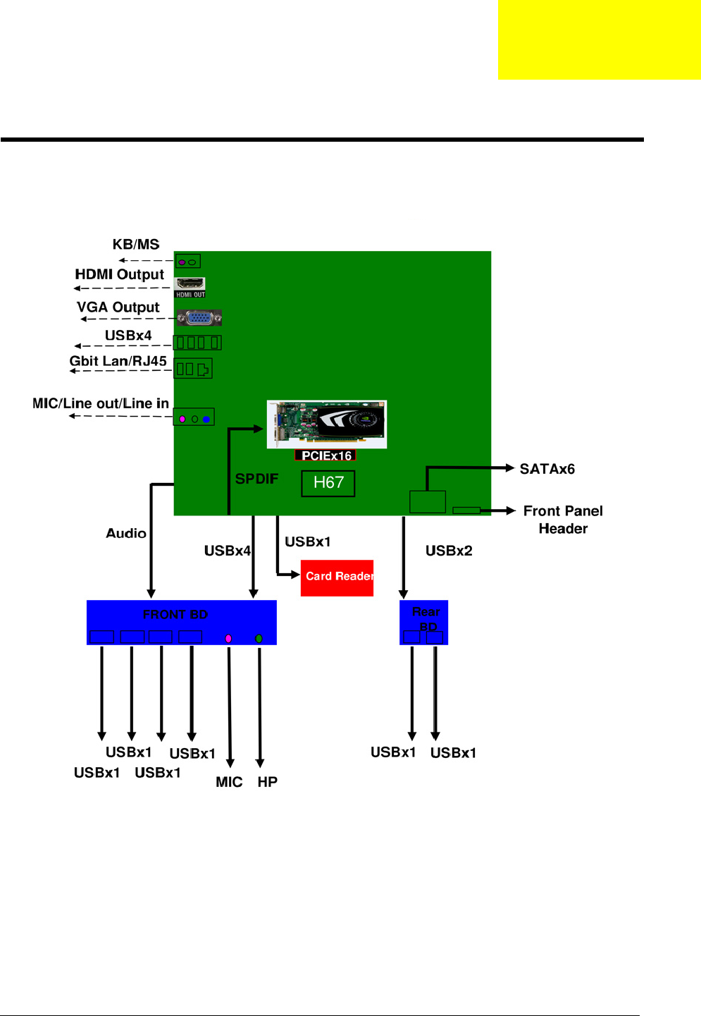
This chapter shows the block diagram and board layout of the computer.
Block Diagram
System Architecture
Chapter 5
60 Chapter 5
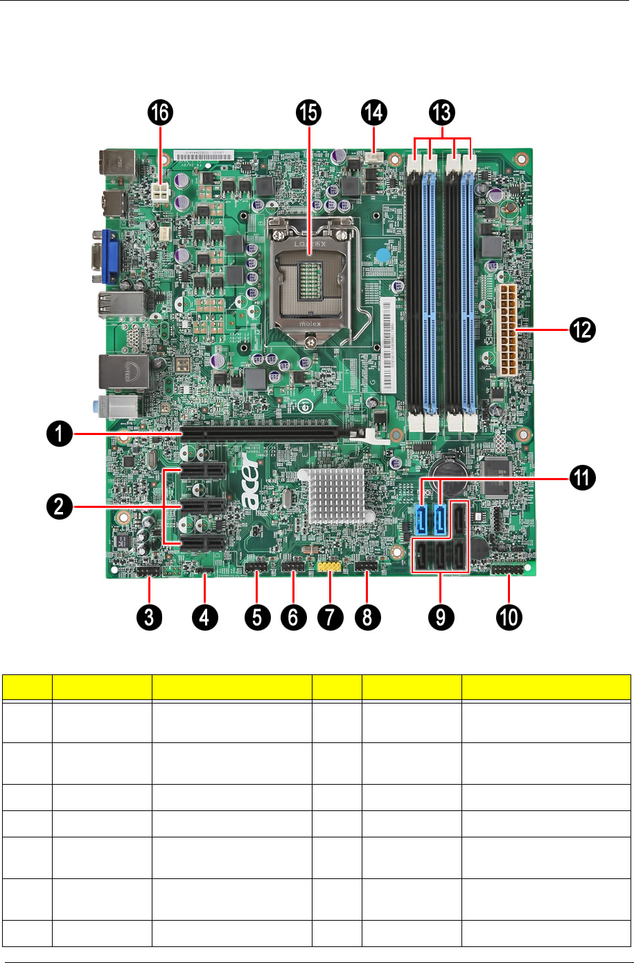
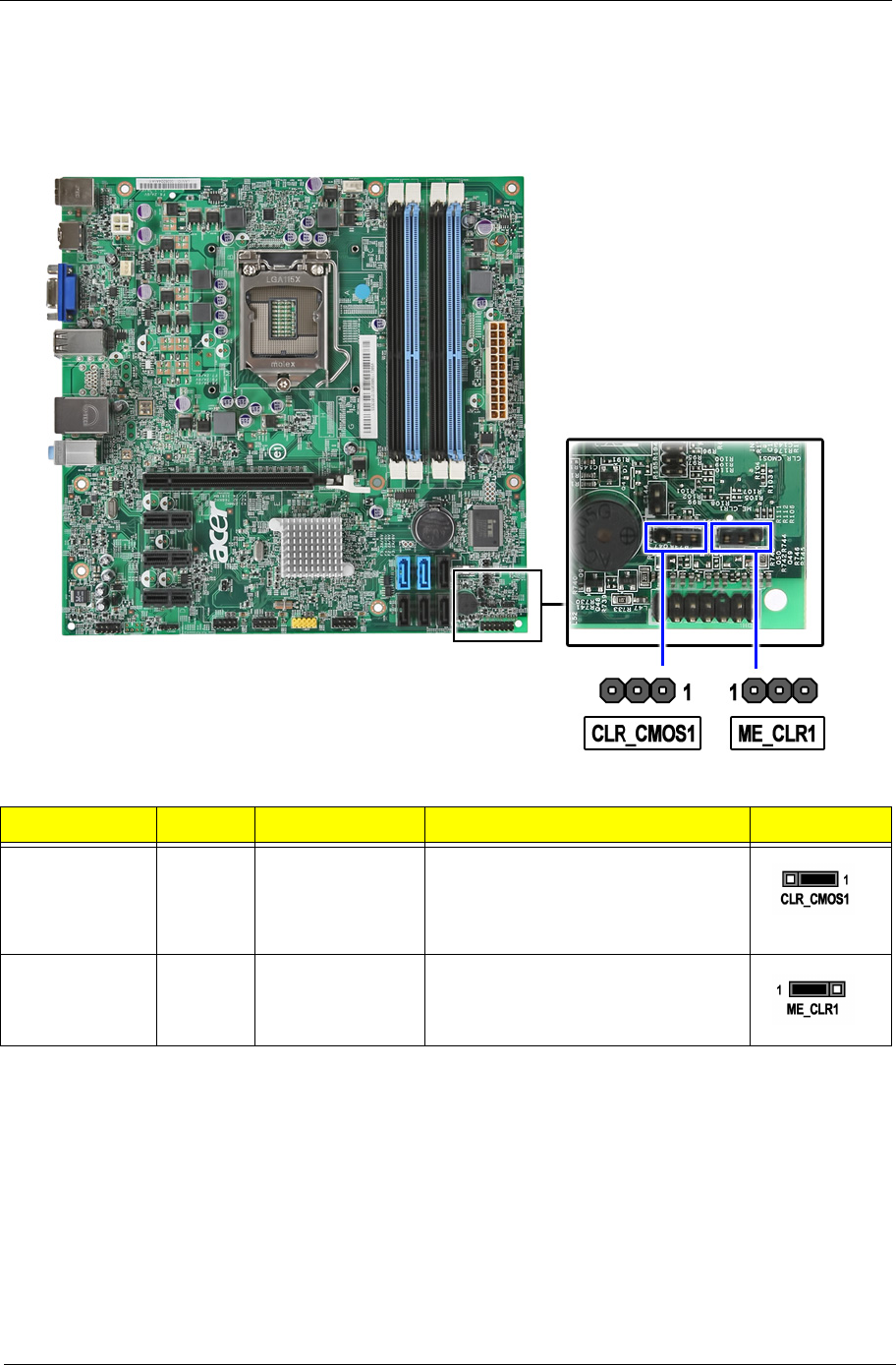
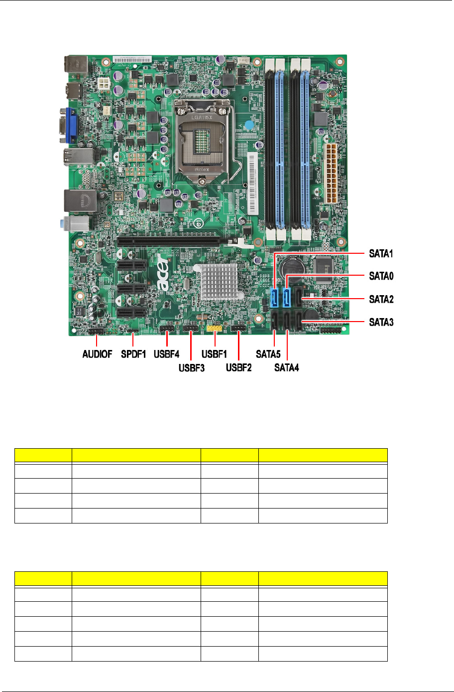
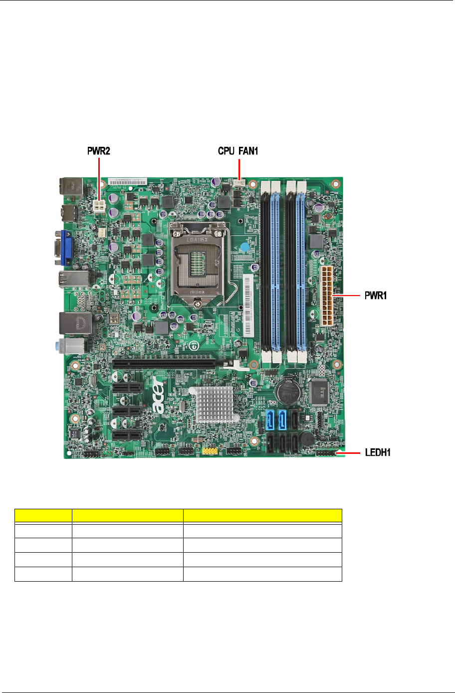
Mainboard Layout
This section shows the major mainboard components.
No Label Description No Label Description
1 PCIE116X1 PCIEx 16 socket 11 SATA0~1 SATA0 and 1 cable
connectors
2 PCIE1~3 PCIEx1 sockets 12 PWR1 24-pin ATX power
connector
3 AUDIO_F Front audio header 13 DIMM1~4 Memory slots DIMM1 to 4
4 SPDIF1 SPDIF audio header 14 CPUFAN1 CPU fan connector
5~8 USBF1~4 Front panel USB
headers
15 U2 CPU Socket
9 SATA2~5 SATA2 to 5 cable
connectors
16 PWR2 4-pin +12V power
connector
10 LEDH1 LED indicator header
Chapter 5 61
Jumper Setting
This section explains how to set the jumper for correct configuration of the main board.
Jumpers with more than one pin are numbered. When setting a jumper, ensure that the jumper caps are
placed on the correct pins.
Jumper Type Description Setting (default) Picture
CLR_CMOS1 3-pin Clear CMOS 1-2: Normal
2-3: Clear
Before clearing the CMOS, make sure
to turn the system off.
ME_CLR1 3-pin Clear ME 1-2: Normal
2-3: ME disabled
62 Chapter 5
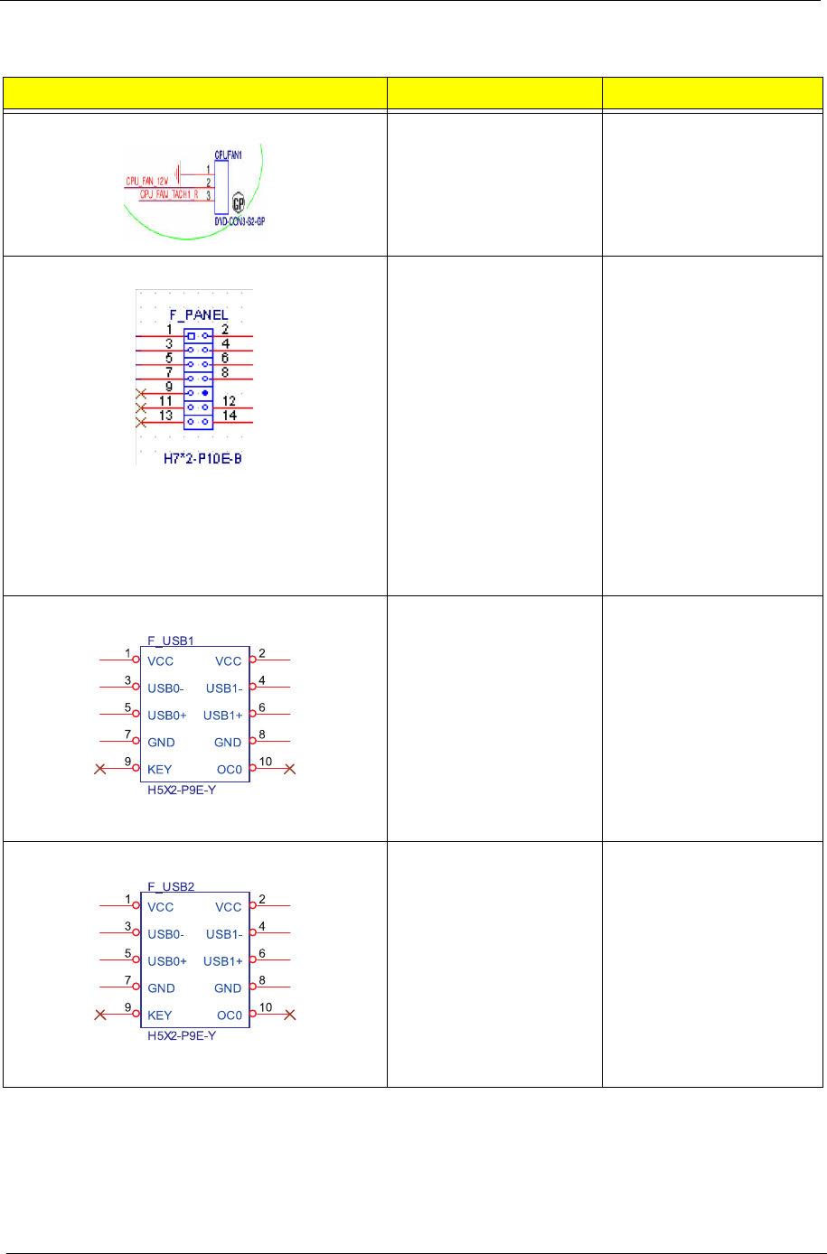
Internal header pin definition
Header Name Function Definition
CPU FAN HEADER 1: GND
2: +12V
3: SENSE
FRONT PANEL HEADER 1: SATALED+
2: ACPI_LED
3: SATALED-
4: PWR_LED
5: GND
6: PWR_SW
7: RESET
8: GND
9: NC
10: Key
11: NC
12: VCC
13: NC
14: -ACTIVE_C
FRONT USB HEADER 1: USBVCC_1
2: USBVCC_1
3: USB0_XN
4: USB1_XN
5: USB0_XP
6: USB1_XP
7:GND
8: GND
9: KEY
10: GND
FRONT USB HEADER
1: USBVCC_2
2: USBVCC_2
3: USB2_XN
4: USB4_XN
5: USB2_XP
6: USB4_XP
7:GND
8: GND
9: KEY
10: GND
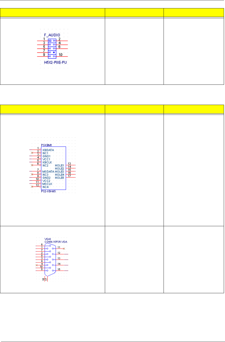
Chapter 5 63
Connector pin definition
FRONT AUDIO HEADER 1: PORT-F_L
2: AUGND
3: PORT-F_R
4: FRONT_AUD_DET
5: PORT-E_R
6: MIC2_JD
7: AUGND
8: KEY
9: PORT-E_L
10: LINE2_JD
Connector Name Function Definition
PSKBMS CONN 1: KBDATA
2: NC
3: GND
4: KBVCCSB
5: KBCLK
6: NC
7: MSDATA
8: NC
9: GND
10: KBVCCSB
11: MSCLK
12: NC
13: GND
14: GND
15: GND
16: GND
17: GND
VGA CONN 1: RED
2: GREEN
3: BLUE
4,11: NC
9: HDMIVCC
12: VDAC_SDAT
13: HSYNC
14: VSYNC
15: VDAC_SCLK
5,6,7,8,10,16,17: GND
Header Name Function Definition
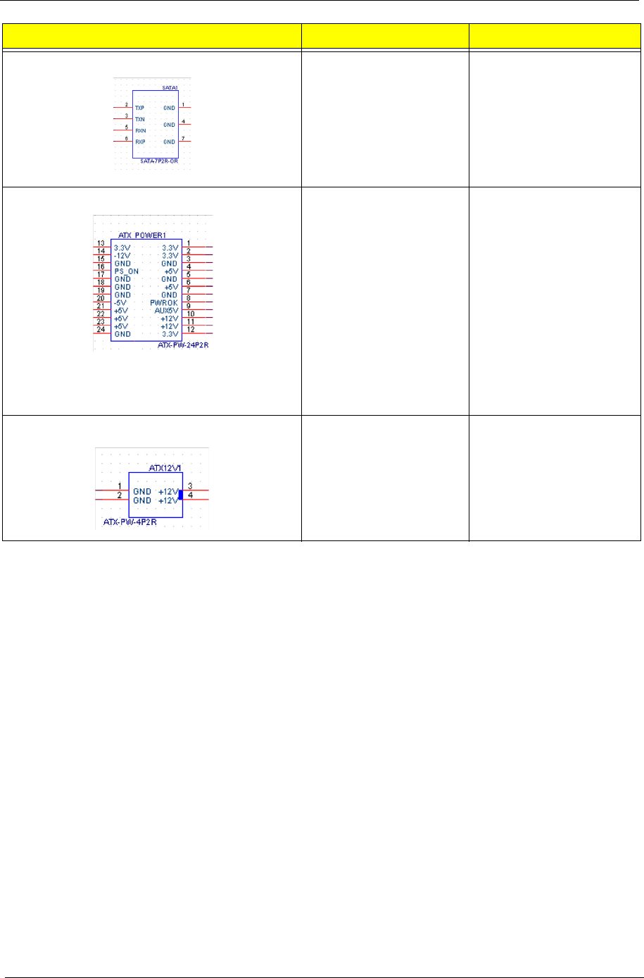
64 Chapter 5
SATA CONN 1: GND
2: SATA0_TX_P
3: SATA0_TX_N
4: GND
5: SATA0_RX_N
6: SATA0_RX_P
7: GND
ATX_POWER CONN 1:VCC3 13:VCC3
2:VCC3 14:-12V
3: GND 15:GND
4:VCC 16:ATX_PSON_L
5:GND 17:GND
6:VCC 18:GND
7:GND 19:GND
8:ATX_PWRGD 20:NC
9:5VSB 21VCC
10:+12V 22:VCC
11:+12V 23:VCC
12:VCC3 24:GND
ATX12V CONN 1: GND
2: GND
3: +12V_4P
4: +12V_4P
Connector Name Function Definition
Chapter 5 65
Connecting Optional Devices
Refer to the following for information on connecting the main board’s optional devices:
SATA0~5: Serial ATA connectors
These connectors are used to support the new Serial ATA devices for the highest datatransfer rates
(3.0 Gb/s), simpler disk drive cabling and easier PC assembly. It elimi-nates limitations of the current Parallel
ATA interface. But maintains register com-patibility and software compatibility with Parallel ATA.
AUDIOF_F: Front Panel Audio header
This header allows the user to install auxiliary front-oriented microphone and line-out ports for easier access.
Pin Signal Name Pin Signal Name
1Ground 2TX+
3TX- 4Ground
5RX- 6RX+
7 Ground
Pin Signal Name Pin Signal Name
1PORT 1L 2AUD_GND
3PORT 1R 4PRESENCE#
5 PORT 2R 6 SENSE1_RETURN
7 SENSE_SEND 8 KEY
9 PORT 2L 10 SENSE2_RETURN

66 Chapter 5
USBF1~4: Front Panel USB headers
The motherboard supports eight USB ports on the rear panel and four USB ports on the front. The USB header
pins description is as follows:
Pin Signal Name Function
1 USBPWR Front Panel USB Power
2 USBPWR Front Panel USB Power
3 USB_FP_P0- USB Port 0 Negative Signal
4 USB_FP_P1- USB Port 1 Negative Signal
5 USB_FP_P0+ USB Port 0 Positive Signal
6 USB_FP_P1+ USB Port 1 Positive Signal
7 GND Ground
8 GND Ground
9 Key No pin
10 USB_FP_OC0 Overcurrent signal
Chapter 5 67
Connecting Case Components
After you have installed the motherboard into a case, you can begin connecting themotherboard components.
Refer to the following:
1. Connect the CPU cooling fan cable to CPUFAN1.
2. Connect the standard power supply connector to PWR2.
3. Connect the case switches and indicator LEDs to the LEDH1.
4. Connect the auxiliary case power supply connector to PWR1.
CPUFAN1: CPU Cooling Fan Power Connector
Pin Signal Name Function
1 GND System ground
2 +12V Power +12V
3 Sense Sensor
4PWM PWM
68 Chapter 5
PWR2: ATX 24-pin Power Connector
PWR1: ATX 12V Power Connector
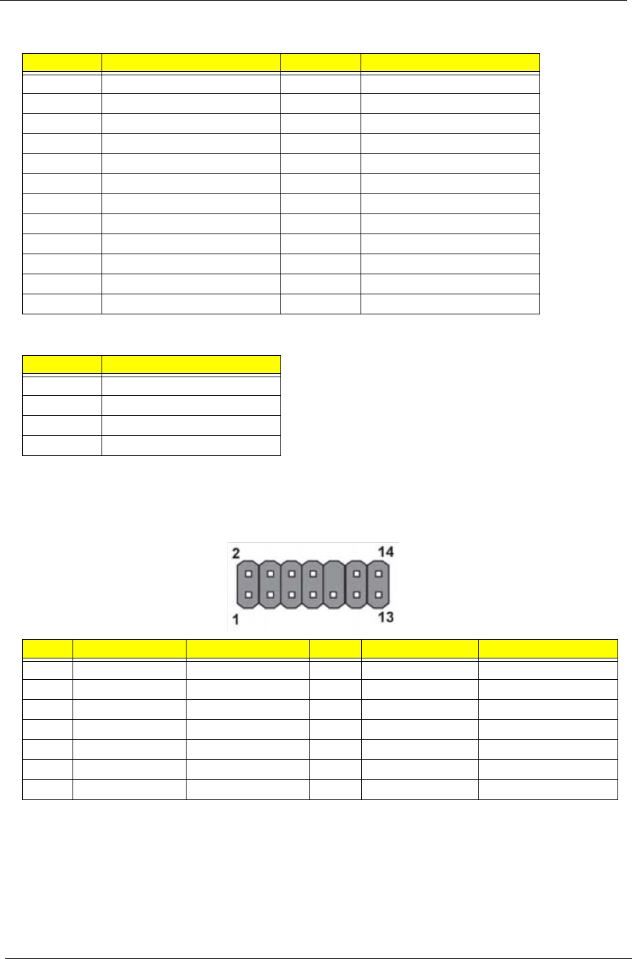
Front Panel Header
The front panel header (LEDH1) provides a standard set of switch and LED headers commonly found on ATX
or micro-ATX cases. Refer to the table below for information:
Pin Signal Name Pin Signal Name
1 +3.3V 13 +3.3V
2 +3.3V 14 -12V
3 Ground 15 Ground
4 +5V 16 PS_ON
5 Ground 17 Ground
6 +5V 18 Ground
7 Ground 19 Ground
8PWRGD 20-5V
9+5VSB 21+5V
10 +12V 22 +5V
11 +12V 23 +5V
12 +3.3V 24 Ground
Pin Signal Name
1 Ground
2 Ground
3+12V
4+12V
Pin Signal Name Function Pin Signal Name Function
1 VCC Reset Switch (+) 2 GLED0 *MSG LED (+)
3 HDD_LEDN Hard disk LED (-) 4 GLED1 *MSG LED (-)
5 GND Reset Switch (-) 6 PWRSW Power Switch (+)
7 HWRST_L Reset Switch (+) 8 GND Power Switch (-)
9 F_PANEL_DET Reserved 10 KEY No pin
11 NC Reserved 12 VCC Reset Switch (+)
13 NC Reserved 14 F_LAN_LED Reset Switch (+)
LEDH1

chapter 6 69
This chapter offers the FRU (Field Replaceable Unit) list in global configuration of the Aspire M3920 desktop
computer. Refer to this chapter whenever ordering the parts to repair or for RMA (Return Merchandise
Authorization).
NOTES:
•When ordering FRU parts, check the most up-to-date information available on your regional web
or channel. For whatever reasons a part number is changed, it will NOT be noted on the printed
Service Guide. For Acer authorized service providers, your Acer office may have a different part
number code from those given in the FRU list of this printed Service Guide. You MUST use the
local FRU list provided by your regional Acer office to order FRU parts for service.
•To scrap or to return the defective parts, follow the local government ordinance or regulations on
how to dispose it properly, or follow the rules set by your regional Acer office on how to return it.
•This document will be updated as more information about the FRU list becomes available.
FRU (Field Replaceable Unit) List
Chapter 6
70 Chapter 6
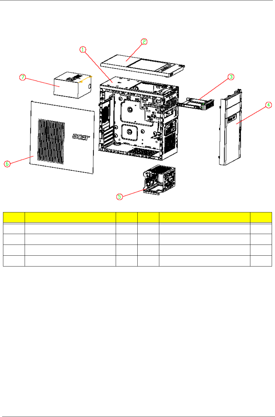
Aspire M3920 Exploded Diagram
NOTE: This section will be updated when more information becomes available.
No. Item Qty No. Item Qty
1 Chassis assembly 1 5 HDD Bracket 1
2Top cover 16Side cover 1
3 Removable HDD Bracket 1 7 Power supply 1
4 Front cover
Chapter 6 71
Aspire M3920 FRU List
Category Part Name Description Acer Part No.
ACCESSORY REMOTE CONTROL PHILIPS
RC2604307/01BG PAIR WITH
RV.11000.007 EMEA FOR WINDOWS7
REMOTE CTRL
PHILIPS RC2604307/
RT.11300.021
REMOTE CONTROL PHILIPS
RC2604302/01B MSFT CODE PAIR WITH
OVU430008 US FOR WINDOWS7
RC PHILIPS WIN7
(US) RC260430
RT.11300.022
RECEIVER PHILIPS OVU710018 WIN7
PHILIPS CODE FOR EMEA, H57 FIXED
FW, PAIR WITH RT.11300.021
PHILIPS OVU710018
WIN7 RECEIVER
PHILIPS
RV.11000.025
RECEIVER PHILIPS OVU430008 WITH
IR BLASTER FOR WINDOWS7
RC PHILIPS WIN7
RECEIVER WITH
RV.11000.023
BOARD F-IO BOARD F-IO BOARD M3 55.SDZ01.001
F-IO BOARD F-IO BOARD M3 55.SDZ01.002
F-IO BOARD F-IO BOARD M1, M3
9802-0500483RZ
55.SF601.001
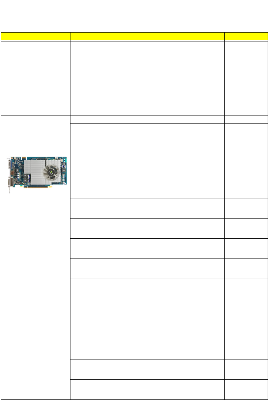
VGA CARD 288-1E153-000AC HD5450
512MB SDDR 3 (64BITS) SAMSUNG DVI
HDMI VGA W/ATX BKT ROHS 4 LAYER
COST DOWN
VGA CARD 5450
512MB SDDR3 VGA/
HDMI/DVI
VG.APC54.503
VGA CARD 288-1E153-200AC AMD
HD5450 512MB 64BITS SDDR3
DVI+HDMI+VGA ATX 4 LAYER COST
DOWN (NEW HYNIX -1.2)
VGA CARD 5450
512MB SDDR3
HYNIX-1.2 DVI
VG.APC54.524
VGA CARD HD5570 1GB DDR 3
(128BITS) SAMSUNG DVI HDMI VGA W/
ATX BA
VGA HD5570 1GB
DDR 3 (128BITS)
SAMSUNG D
VG.APC55.701
VGA CARD 288-2E142-201AC AMD
HD5570 1GB 128BITS SDDR3
DVI+HDMI+VGA ATX (NEW HYNIX -1.2)
VGA CARD HD5570
1GB SDDR3 HYNIX
1.2 DVI
VG.APC55.722
VGA CARD 81D685-469016 NV G315
512MB (64BIT) DDR3 DVI HDMI VGA ATX
BRACKET ROHS (SAMSUNG)
NV GT315 512MB
DDR3 DVI/HDMI/
VGA W/ATX B
VG.ECS31.502
VGA CARD PCPARTNER 288-30N58-
010AC NVIDIA GT330 2GB SDDR2
DVI+HDMI LP
PCP NV GT330 2GB
DDR2 SDI DVI/HDMI/
VGA A
VG.PCPT3.301
VGA CARD 288-30N58-110AC NV GT330
2GB DDR2 DVI+HDMI+VGA ATX (HYNIX)
PCP NV GT330
DDR2 DVI/HDMI/
DSUB ATX HYN.
VG.PCPT3.302
VGA CARD 288-1N162-001AC GT420
1GB 128BIT DVI-I+HDMI+VGA ATX
SAMSUNG
PCP NV GT410 1GB
DDR3 SDI DVI/HDMI/
ATX
VG.PCPT4.201
VGA CARD 288-1N162-101AC GT420
1GB 128BIT DVI-I+HDMI+VGA ATX
HYNIX
PCP NV GT420 1GB
DDR3 HYNIX DVI/
HDMI/ATX
VG.PCPT4.202
NV 315 512MB SDDR3 DVI+HDMI+VGA
ATX (SAMSUNG)
PCP NV GT315
512MB SDDR3 SDI
DVI/HDMI
VG.PCPT3.151
288-1N141-201AC NV 315 512MB 64BITS
SDDR3 DVI+HDMI+VGA ATX (NEW
HYNIX -1.2)
PCP NV GT315
512MB SDDR3
HYNIX-1.2 DVI
VG.PCPT3.162
NV G315 512MB (64BIT) DDR3 DVI HDMI
VGA ATX BRACKET ROHS
NV GT315 512MB
DDR3 DVI/HDMI/
VGA W/ATX B
VG.ECS31.501
72 Chapter 6
BOARD 288-5N118-010AC NV GT320 1GB
SDDR3 DVI+HDMI+VGA ATX
(SAMSUNG)
VGA CARD GT320
1GB SDDR3 SDI DVI
HDMI
VG.PCPT3.201
288-5N118-210AC NV GT320 1GB DDR3
DVI+HDMI+VGA ATX (HYNIX 1.2NS)
VGA CARD GT320
1GB DDR3 HYNIX-
1.2 DVI
VG.PCPT3.203
TV TUNER CARD AVERMEDIA H753-A
PCIE HYBRID ATSC, S/W ENCODER,
ATX BRACKET
AVERMEDIA H753-A
TV TUNER CARD
PCIE HYBR
TU.10500.072
TV TUNER CARD AVERMEDIA H753-D
PCIE HYBRID DVB-T, S/W ENCODER,
ATX BRACKET
AVERMEDIA H753-D
TV TUNER CARD
PCIE HYBR
TU.10500.074
TV TUNER CARD AVERMEDIA H753-C
PCIE HYBRID DMB-TH S/W ENCODER
ATX BRACKET
AVERMEDIA H753-C
TV TUNER CARD
PCIE HYBR
TU.10500.078
MODEM CARD D-1156E#/A10A PCI-EX1
CARD LSI UNIVERSAL MODEM (PCI-E)
56K V.92 - CONCORDE (C40)
MODEM D-1156E#/
A10A (PCI-E X1)
FX.10100.002
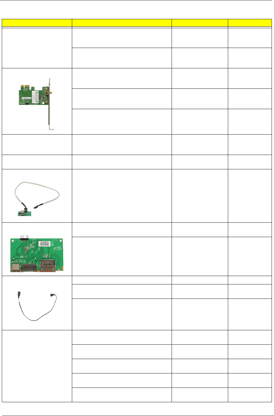
WN7601R, RALINK RT3090, 802.11B/G/N
1X1 WLAN PCI-E X1 CARD
WLAN 802.11BGN
RALINK RT3090
NI.10200.037
USB BOARD 3.0 IOI RA351 KIT NEC
?PD720200 2 EXTERMAL PORTS 1 PATA
4-PIN POWER CONNECTOR 50MM
HEIGHT PCB 700MM POWER Y-CABLE
USB 3.0 CARD PCI-E
KIT 30L USED
PA.14000.041
IOI 16-IN-1 CR M1/M3 W/3.5", USB2.0,
USBSET UT330-LK W/MICRO SD, M2
IOI 16-IN-1 CR M1/
M3 W/3.5", USB2.0
CR.10400.071
NS 16-IN-1 CR M1/M3 W/3.5", USB2.0,
REALTEK RT5181 W/MICRO SD, M2
NS 16-IN-1 CR M1/
M3 W/3.5", USB2.0
CR.10400.100
CABLE HDD SATA CABLE C.A. SATA HDD M3 50.SDS01.001
HDD/ODD SATA CABLE C.A.SATA HDD
BOXER?
50.SC101.003
HDD/ODD SATA CABLE C.A. SATA HDD
BOXERII VSO
50.G8101.002
POWER CORD 1800MM 250V EURO POWER CORD
1800MM 250V EURO
27.01518.0J1
POWER CORD 250V 3PIN 1800MM UK POWER CORD
1800MM 250V UK
27.03118.031
POWER CORD 125V 7A 3G JAPAN CORD VCTF 3G 7A/
125V(JAPAN)
27.01518.181
POWER CORD 110V 3PIN UL USA POWER CORD 110V
UL USA
27.01518.0I1
POWER CORD AUSTRALIA WITH
TESTED TAG
POWER CORD ACA
WITH TESTED TAG
27.01518.0N1
Category Part Name Description Acer Part No.
Chapter 6 73
DVI TO HDMI CONVERTER FOR AMD
HD3XXX SERIES
HDMI FEMALE TO
DVI-D MALE ADAP
D0.HD3XX.001
CONNECTOR ATI DVI TO HDMI
ADAPTER
ATI DVI TO HDMI
ADAPTER
D0.HDAMD.002
HDMI ADAPTER CONNECTOR FOR
NVIDIA PRODUCTS
HDMI ADAPTER
FOR NVIDIA
D0.HDMNV.001
DVI TO VGA DONGLE CONNECTOR DVI TO VGA
DONGLE
D0.VGA26.P01
CASE/COVER/BRACKET
ASSEMBLY
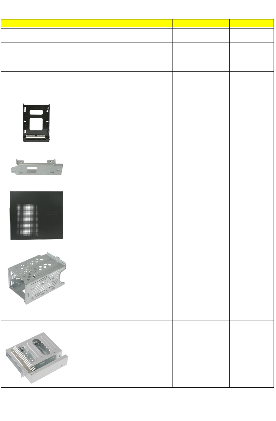
HDD CARRIER FOR 2ND HDD ASSY HDD-
CARRIER AWASP
60.SF601.002
REAR USB BRACKET BRKT USB W/O
SPDIF
33.SF601.002
LEFT SIDE COVER LEFT SIDE COVER
M3
60.SF601.001
HDD CAGE BRACKET BRKT HDD CAGE
BKT
33.SF601.001
TOP COVER W/POWER SWITCH
BOARD & POWER SWITCH CABLE
TOP COVER ASSY
M3
60.SDZ01.004
HDD CAGE FOR 2ND HDD ODD TO HDD ASSY
M351
60.SF601.003
Category Part Name Description Acer Part No.
74 Chapter 6
FRONT BEZEL M350 W/POWER LED
CABLE
FRONT-BEZEL-
ASSY-M350
60.SF701.002
FRONT BEZEL M351 W/POWER LED
CABLE
FRONT-BEZEL-
ASSY-M351
60.SDZ01.006
CRT COVER CVR CRT BOXER II 42.SF601.001
HDMI DUMMY COVER HDMIC-1 42.SF601.002
ASSEMBLY MAIN CHASSIS W/ MB
SUPPORT ASSY & TOP IO ASSY & TOP
RIGHT SIDE COVER
MAIN CHASSIS
ASSY M3
60.SF701.001
MAINBOARD SUPPORT ASSY MB SUPPORT
ASSY
60.SDS01.003
TOP RIGHT SIDE COVER TOP RIGHT SIDE
COVER ASSY M3
60.SDZ01.003
TOP IO W/F-IO BOARD TOP IO ASSY M3 60.SDZ01.002
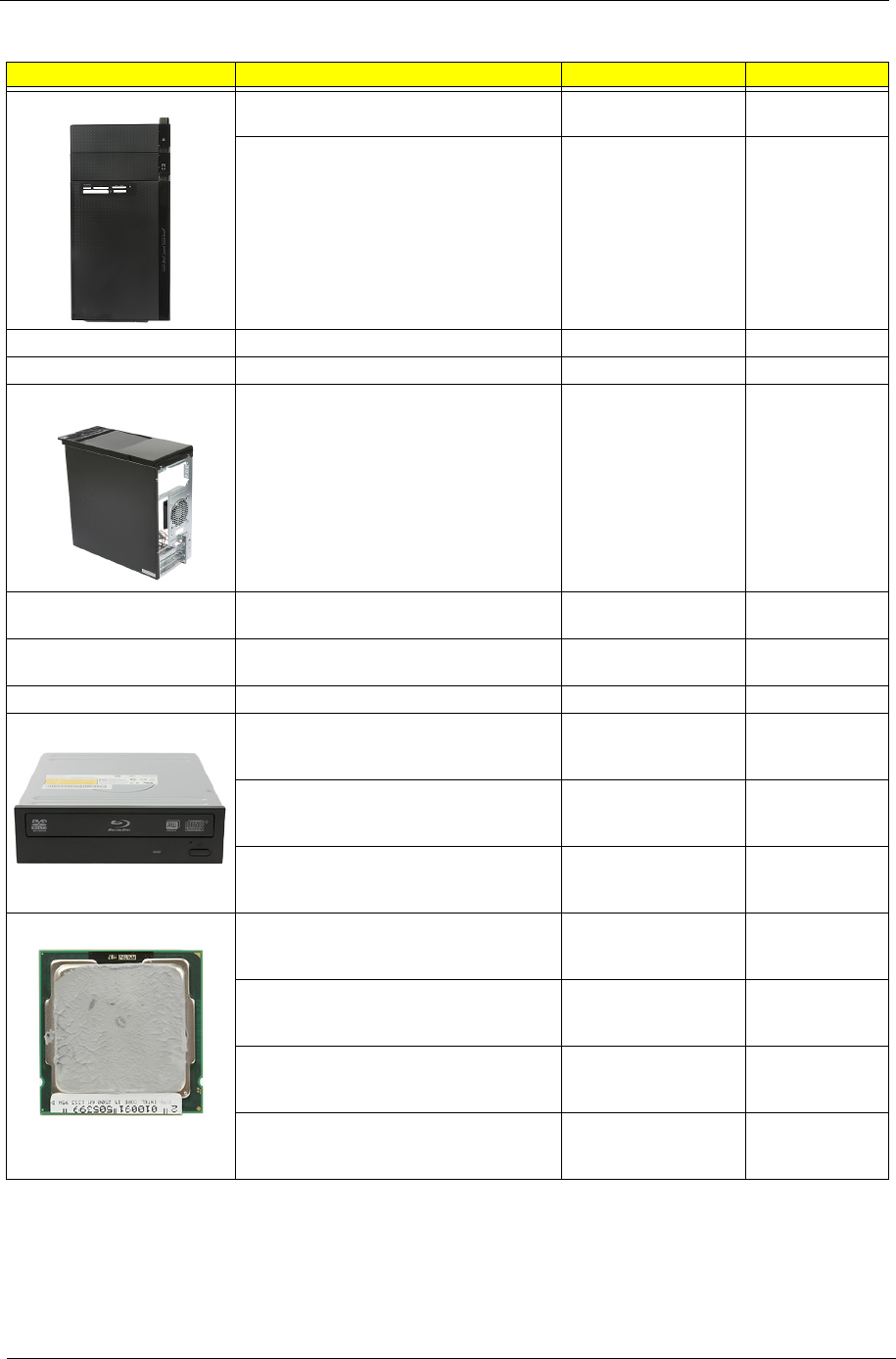
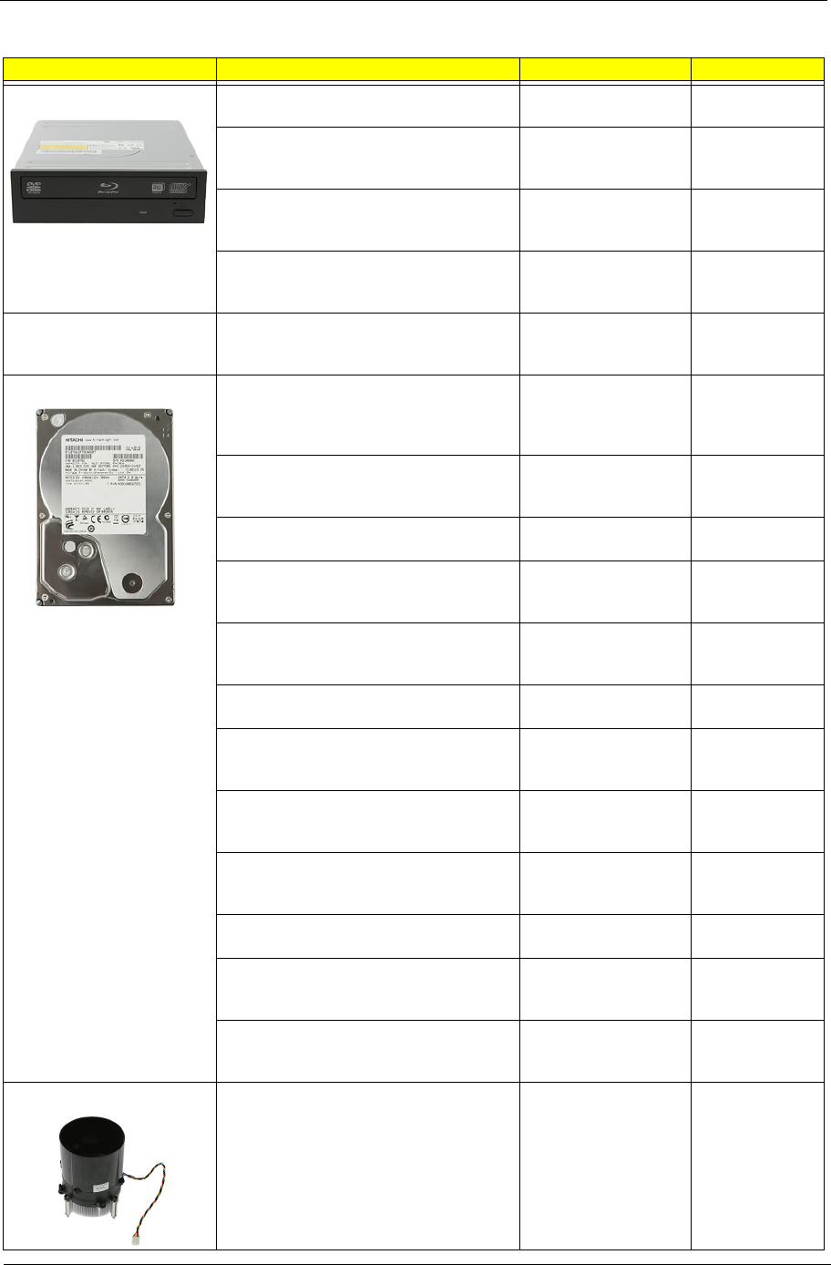
COMBO MODULE ODD PIONEER BD COMBO SATA HH
HF+W7 6X HLDS CH20N W/BEZEL
BLACK
BD COMBO HH
HF+W7 HLDS
CH20N
KO.0060D.005
ODD PLDS BD COMBO SATA HH DL 6X
DH-6E2S LF W/BLACK BEZEL FOR
WINDOWS7
BD COMBO HH W7
PLDS DH-6E2S
KO.0060F.002
ODD PLDS BD ROM HH DL 4X DH-4O3S
LF STANDARD BEZEL SATA (FOR
WINDOWS7)
BD ROM HH W7
SATAPLDS DH-4O3S
KV.0040F.002
CPU/PROCESSOR CPU INTEL CORE I7 2600 3.4G 8M 1333
95W K-0 LGA-1155 SANDY BRIDGE
IC CPU SANDY
BRIDGE I7-2600
3.40G 8M FC-
KC.26001.CI7
CPU INTEL CORE I5 2500 3.3G 6M 1333
95W K-0 LGA1155 SANDY BRIDGE
IC CPU SANDY
BRIDGE I5-2500
3.30G 6M FC-
KC.25001.CI5
CPU INTEL CORE I5 2400 3.1G 6M 1333
95W K-0 LGA1155 SANDY BRIDGE
IC CPU SANDY
BRIDGE I5-2400
3.10G 6M FC-
KC.24001.CI5
CPU INTEL CORE I5 2300 2.8G 6M 1333
95W D-2 LGA1155 SANDY BRIDGE
QUAD CORE
IC CPU SANDY
BRIDGE I5-2300
2.80G 6M FC-
KC.23001.CI5
Category Part Name Description Acer Part No.
Chapter 6 75
DVD-RW DRIVE ODD SUPER-MULTI DRIVE HH DL 16X
GH60N LF+HF BLK BZL SATA HF+
ODD HH SM HF+W7
HLDS GH60N
KU.0160D.052
ODD PLDS Super-Multi DRIVE HH DL
16X DH-16ABSH LF Black Bezel
(HF+Win7) SATA
16X ODD PLDS DH-
16ABSH SM HH BLK
W7
KU.0160F.011
ODD HLDS DVD-ROM HH 16X TRAY
DH20N LF BLACK BEZEL SATA HF+WIN
7
DVD ROM HH
HF+W7 HLDS
DH20N
KV.0160D.016
ODD PLDS DVD-ROM HH DL 16X TRAY
DH-16D5SH LF BLACK BEZEL SATA
HF+WIN 7
DVD ROM HH
HF+W7 DH-16D5SH
KV.0160F.002
FAN FAN FAN9225
KDE1209PTV3
13.MS.AF.GN
HI.S150F.002
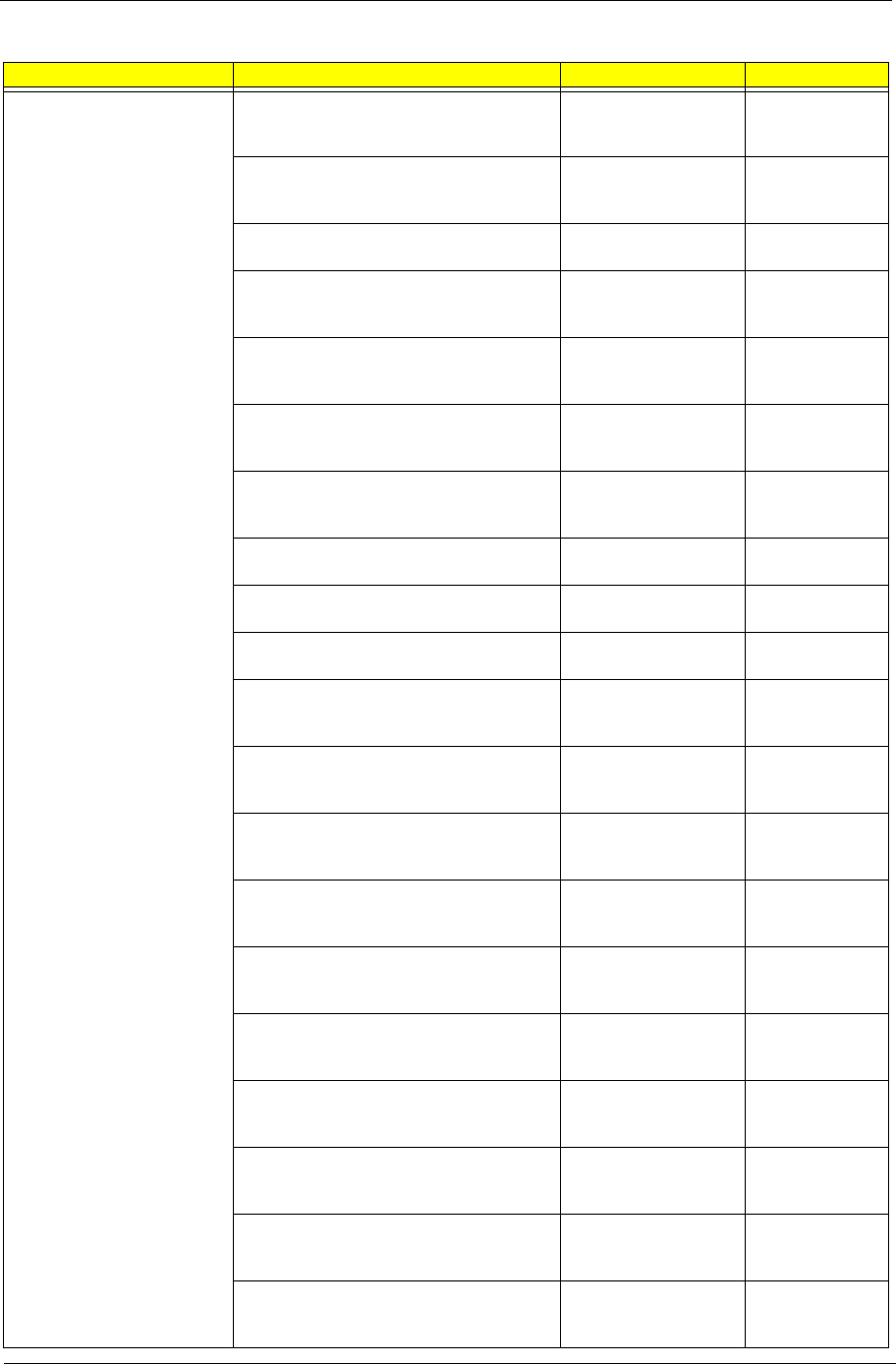
HDD/HARD DISK DRIVE HDD 320GB 3.5" 7200RPM SATA II 16MB
HGST HDS721032CLA362 JUPITER
HDD 320GB 3.5"
HGST
HDS721032CLA362
7.2K
KH.32007.011
HDD 320G 7200RPM 3.5" SEAGATE
ST3320418AS( PHARAOH BP) SATA II
16MB LF F/W:CC44
HDD 320GB 3.5"
SEAGATE
ST3320418AS 7.2K
KH.32001.020
HDD 500GB 3.5" 7200RPM SATA II 16MB
HGST HDS721050CLA362 JUPITER
HDD 500GB HGST
HDS721050CLA362
KH.50007.012
HDD 500G 7200RPM 3.5" SEAGATE
ST3500418AS(PHARAOH PB) SATA II
16MB LF F/W:CC44
HDD 500GB 3.5"
SEAGATE
ST3500418AS 7.2K
KH.50001.019
HDD 3.5" 500GB 7200RPM SATA WD
XL320M WD5000AAKS-22M9A0
HDD 500GB
WD5000AAKS-
22V1A0
KH.50008.014
HDD 640GB 3.5" 7200RPM SATA II 32MB
HGST HDS721064CLA332 JUPITER
HDD 640GB HGST
HDS721064CLA332
KH.64007.002
HDD 640GB 3.5" 7200RPM SATA II WD
WD6400AAKS-22A7B2 XL320-M
HDD 640GB WD
WD6400AAKS-
22A7B2
KH.64008.003
HDD 1TB 3.5" 5400RPM SATAII
WD10EADS-22M4B0 8MB GP
HDD 1TB
WD10EADS-22M2B0
GP
KH.01K08.005
HDD 1TB 3.5" 5400RPM WD WD10EARS-
22Y5B1 GP 5.4K
HDD 1TB 3.5" WD
WD10EARS-22Y5B1
GP 5.4K
KH.01K08.008
HDD 1TB 3.5" 7200RPM SATA II 32MB
HGST HDS721010CLA332 JUPITER
HDD 1TB HGST
HDS721010CLA332
KH.01K07.003
HDD 1TB 7200RPM 3.5" SEAGATE
ST31000528AS(PHARAOH BP) SATA II
32MB LF F/W:CC44
HDD 1TB 3.5"
SEAGATE
ST31000528AS 7.2K
KH.01K01.013
HDD 1.5TB 3.5" 7200RPM SATA
SEAGATE BRINKS ST31500341AS 32MB
CC4H 7
HDD 1.5TB SGT
ST31500341AS 7.2
KH.15K01.002
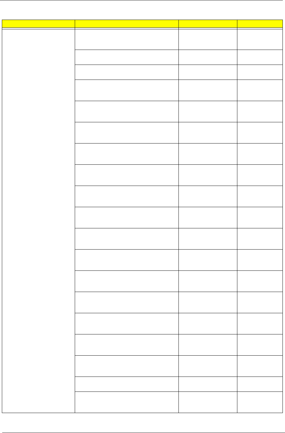
HEATSINK COOLER INTEL LGA1156 AVC
ZGUL00A201 W/I 72MM DUCT 35MM HS
W/I FAN 9225 W/I 72MM FAN DUCT
INTEL LGA1156 95W
COOLER AVC 72MM
DUCT
HI.10800.048
Category Part Name Description Acer Part No.

76 Chapter 6
KEYBOARD KEYBOARD KIT 104KEY RF2.4 LITE-ON
SK-9660B BLACK US WITH MOUSE
KB&MS PACK RF
LITEON A1B US
KB.RF40B.042
KEYBOARD KIT 104KEY RF2.4 LITE-ON
SK-9660B BLACK TRADITIONAL
CHINESE WITH MOUSE
KB&MS PACK RF
LITEON A1B TC
KB.RF40B.043
KEYBOARD KIT 104KEY RF2.4 LITE-ON
SK-9660B BLACK SIMPLIFIED CHINESE
WITH MOUSE
KB&MS PACK RF
LITEON A1B S-
CHINESE
KB.RF40B.044
KEYBOARD KIT 104KEY RF2.4 LITE-ON
SK-9660B BLACK US INTERNATIONAL
WITH MOUSE
KB&MS PACK RF
LITEON A1B US(INL)
KB.RF40B.045
KEYBOARD KIT 104KEY RF2.4 LITE-ON
SK-9660B BLACK ARABIC/ENGLISH
WITH MOUSE
KB&MS PACK RF
LITEON A1B EN(AR)
KB.RF40B.046
KEYBOARD KIT 104KEY RF2.4 LITE-ON
SK-9660B BLACK THAILAND WITH
MOUSE
KB&MS PACK RF
LITEON A1B TH
KB.RF40B.047
KEYBOARD KIT 105KEY RF2.4 LITE-ON
SK-9660B BLACK SPANISH WITH
MOUSE
KB&MS PACK RF
LITEON A1B ES
KB.RF40B.048
KEYBOARD KIT 105KEY RF2.4 LITE-ON
SK-9660B BLACK PORTUGUESE WITH
MOUSE
KB&MS PACK RF
LITEON A1B PT
KB.RF40B.049
KEYBOARD KIT 105KEY RF2.4 LITE-ON
SK-9660B BLACK CANADIAN FRENCH
WITH MOUSE
KB&MS PACK RF
LITEON A1B CA-FR
KB.RF40B.050
KEYBOARD KIT 107KEY RF2.4 LITE-ON
SK-9660B BLACK BRAZILIAN
PORTUGUESE WITH MOUSE
KB&MS PACK RF
LITEON A1B XC
KB.RF40B.051
KEYBOARD KIT 109KEY RF2.4 LITE-ON
SK-9660B BLACK JAPANESE WITH
MOUSE
KB&MS PACK RF
LITEON A1B JA
KB.RF40B.052
KEYBOARD KIT 105KEY RF2.4 LITE-ON
SK-9660B BLACK GERMAN WITH
MOUSE
KB&MS PACK RF
LITEON A1B DE
KB.RF40B.053
KEYBOARD KIT 105KEY RF2.4 LITE-ON
SK-9660B BLACK ITALIAN WITH MOUSE
KB&MS PACK RF
LITEON A1B IT
KB.RF40B.054
KEYBOARD KIT 105KEY RF2.4 LITE-ON
SK-9660B BLACK FRENCH WITH
MOUSE
KB&MS PACK RF
LITEON A1B FR
KB.RF40B.055
KEYBOARD KIT 105KEY RF2.4 LITE-ON
SK-9660B BLACK SWEDISH WITH
MOUSE
KB&MS PACK RF
LITEON A1B SV
KB.RF40B.056
KEYBOARD KIT 105KEY RF2.4 LITE-ON
SK-9660B BLACK UK WITH MOUSE
KB&MS PACK RF
LITEON A1B UK
KB.RF40B.057
KEYBOARD KIT 105KEY RF2.4 LITE-ON
SK-9660B BLACK DUTCH WITH MOUSE
KB&MS PACK RF
LITEON A1B DUTCH
KB.RF40B.058
KEYBOARD KIT 105KEY RF2.4 LITE-ON
SK-9660B BLACK SWISS/G WITH
MOUSE
KB&MS PACK RF
LITEON A1B SW
KB.RF40B.059
KEYBOARD KIT 105KEY RF2.4 LITE-ON
SK-9660B BLACK BELGIUM WITH
MOUSE
KB&MS PACK RF
LITEON A1B BE
KB.RF40B.060
KEYBOARD KIT 105KEY RF2.4 LITE-ON
SK-9660B BLACK ICELANDIC WITH
MOUSE
KB&MS PACK RF
LITEON A1B
ICELANDIC
KB.RF40B.061
Category Part Name Description Acer Part No.
Chapter 6 77
KEYBOARD KEYBOARD KIT 105KEY RF2.4 LITE-ON
SK-9660B BLACK NORWEGIAN WITH
MOUSE
KB&MS PACK RF
LITEON A1B NO
KB.RF40B.062
KEYBOARD KIT 104KEY RF2.4 LITE-ON
SK-9660B BLACK HEBREW WITH
MOUSE
KB&MS PACK RF
LITEON A1B HE
KB.RF40B.063
KEYBOARD KIT 105KEY RF2.4 LITE-ON
SK-9660B BLACK POLISH WITH MOUSE
KB&MS PACK RF
LITEON A1B PL
KB.RF40B.064
KEYBOARD KIT 105KEY RF2.4 LITE-ON
SK-9660B BLACK SLOVENIAN WITH
MOUSE
KB&MS PACK RF
LITEON A1B SL
KB.RF40B.065
KEYBOARD KIT 105KEY RF2.4 LITE-ON
SK-9660B BLACK SLOVAK WITH MOUSE
KB&MS PACK RF
LITEON A1B
SLOVAK
KB.RF40B.066
KEYBOARD KIT 104KEY RF2.4 LITE-ON
SK-9660B BLACK RUSSIAN WITH
MOUSE
KB&MS PACK RF
LITEON A1B RU
KB.RF40B.067
KEYBOARD KIT 105KEY RF2.4 LITE-ON
SK-9660B BLACK HUNGARIAN WITH
MOUSE
KB&MS PACK RF
LITEON A1B HU
KB.RF40B.068
KEYBOARD KIT 104KEY RF2.4 LITE-ON
SK-9660B BLACK GREEK WITH MOUSE
KB&MS PACK RF
LITEON A1B GR
KB.RF40B.069
KEYBOARD KIT 105KEY RF2.4 LITE-ON
SK-9660B BLACK DANISH WITH MOUSE
KB&MS PACK RF
LITEON A1B DA
KB.RF40B.070
KEYBOARD KIT 104KEY RF2.4 LITE-ON
SK-9660B BLACK CZECH WITH MOUSE
KB&MS PACK RF
LITEON A1B CZ
KB.RF40B.071
KEYBOARD KIT 105KEY RF2.4 LITE-ON
SK-9660B BLACK ROMANIAN WITH
MOUSE
KB&MS PACK RF
LITEON A1B RO
KB.RF40B.072
KEYBOARD KIT 105KEY RF2.4 LITE-ON
SK-9660B BLACK TURKISH WITH
MOUSE
KB&MS PACK RF
LITEON A1B TR(F-
TYPE)
KB.RF40B.073
KEYBOARD KIT 105KEY RF2.4 LITE-ON
SK-9660B BLACK TURKISH-Q WITH
MOUSE
KB&MS PACK RF
LITEON A1B TR(Q-
TYPE)
KB.RF40B.074
KEYBOARD KIT 105KEY RF2.4 LITE-ON
SK-9660B BLACK ARABIC/FRENCH
WITH MOUSE
KB&MS PACK RF
LITEON A1B FR(AR)
KB.RF40B.075
KEYBOARD KIT 104KEY RF2.4 LITE-ON
SK-9660B BLACK KAZAKH WITH
MOUSE
KB&MS PACK RF
LITEON A1B
KAZAKH
KB.RF40B.076
KEYBOARD KIT 104KEY RF2.4 LITE-ON
SK-9660B BLACK TURKMEN WITH
MOUSE
KB&MS PACK RF
LITEON A1B
TURKMEM
KB.RF40B.077
KEYBOARD KIT 105KEY RF2.4 LITE-ON
SK-9660B BLACK NORDIC WITH
MOUSE
KB&MS PACK RF
LITEON A1B NOR
KB.RF40B.078
KEYBOARD KIT 105KEY RF2.4 LITE-ON
SK-9660B BLACK ENGLISH/CANADIAN
FRENCH WITH MOUSE
KB&MS PACK RF
LITEON A1B US/CA-
FR
KB.RF40B.079
KEYBOARD KIT 105KEY RF2.4 LITE-ON
SK-9660B BLACK CZECH/SLOVAK WITH
MOUSE
KB&MS PACK RF
LITEON A1B CZ(SK)
KB.RF40B.080
KEYBOARD KIT 105KEY RF2.4 LITE-ON
SK-9660B BLACK SWISS/FR WITH
MOUSE
KB&MS PACK RF
LITEON A1B SWISS/
FR
KB.RF40B.081
Category Part Name Description Acer Part No.
78 Chapter 6
KEYBOARD KEYBOARD KIT 106KEY RF2.4 LITE-ON
SK-9660B BLACK KOREAN WITH
MOUSE
KB&MS PACK RF
LITEON A1B KO
KB.RF40B.082
KEYBOARD KIT 105KEY RF2.4 LITE-ON
SK-9660B BLACK SPANISH LATIN
KB&MS PACK RF
LITEON A1B ES(LA)
KB.RF40B.092
KEYBOARD KIT 104KEY RF2.4 PRIMAX
KBRF36211 BLACK US WITH MOUSE
KB&MS PACK RF
PRIMAX A1B US
KB.RF40P.001
KEYBOARD KIT 104KEY RF2.4 PRIMAX
KBRF36211 BLACK TRADITIONAL
CHINESE WITH MOUSE
KB&MS PACK RF
PRIMAX A1B TC
KB.RF40P.002
KEYBOARD KIT 104KEY RF2.4 PRIMAX
KBRF36211 BLACK SIMPLIFIED
CHINESE WITH MOUSE
KB&MS PACK RF
PRIMAX A1B S-
CHINESE
KB.RF40P.003
KEYBOARD KIT 104KEY RF2.4 PRIMAX
KBRF36211 BLACK US INTERNATIONAL
WITH MOUSE
KB&MS PACK RF
PRIMAX A1B US(INL)
KB.RF40P.004
KEYBOARD KIT 104KEY RF2.4 PRIMAX
KBRF36211 BLACK ARABIC/ENGLISH
WITH MOUSE
KB&MS PACK RF
PRIMAX A1B EN(AR)
KB.RF40P.005
KEYBOARD KIT 104KEY RF2.4 PRIMAX
KBRF36211 BLACK THAILAND WITH
MOUSE
KB&MS PACK RF
PRIMAX A1B TH
KB.RF40P.006
KEYBOARD KIT 105KEY RF2.4 PRIMAX
KBRF36211 BLACK SPANISH WITH
MOUSE
KB&MS PACK RF
PRIMAX A1B ES
KB.RF40P.007
KEYBOARD KIT 105KEY RF2.4 PRIMAX
KBRF36211 BLACK PORTUGUESE WITH
MOUSE
KB&MS PACK RF
PRIMAX A1B PT
KB.RF40P.008
KEYBOARD KIT 105KEY RF2.4 PRIMAX
KBRF36211 BLACK CANADIAN FRENCH
WITH MOUSE
KB&MS PACK RF
PRIMAX A1B CA-FR
KB.RF40P.009
KEYBOARD KIT 107KEY RF2.4 PRIMAX
KBRF36211 BLACK BRAZILIAN
PORTUGUESE WITH MOUSE
KB&MS PACK RF
PRIMAX A1B XC
KB.RF40P.010
KEYBOARD KIT 109KEY RF2.4 PRIMAX
KBRF36211 BLACK JAPANESE WITH
MOUSE
KB&MS PACK RF
PRIMAX A1B JA
KB.RF40P.011
KEYBOARD KIT 105KEY RF2.4 PRIMAX
KBRF36211 BLACK GERMAN WITH
MOUSE
KB&MS PACK RF
PRIMAX A1B DE
KB.RF40P.012
KEYBOARD KIT 105KEY RF2.4 PRIMAX
KBRF36211 BLACK ITALIAN WITH
MOUSE
KB&MS PACK RF
PRIMAX A1B IT
KB.RF40P.013
KEYBOARD KIT 105KEY RF2.4 PRIMAX
KBRF36211 BLACK FRENCH WITH
MOUSE
KB&MS PACK RF
PRIMAX A1B FR
KB.RF40P.014
KEYBOARD KIT 105KEY RF2.4 PRIMAX
KBRF36211 BLACK SWEDISH WITH
MOUSE
KB&MS PACK RF
PRIMAX A1B SV
KB.RF40P.015
KEYBOARD KIT 105KEY RF2.4 PRIMAX
KBRF36211 BLACK UK WITH MOUSE
KB&MS PACK RF
PRIMAX A1B UK
KB.RF40P.016
KEYBOARD KIT 105KEY RF2.4 PRIMAX
KBRF36211 BLACK DUTCH WITH
MOUSE
KB&MS PACK RF
PRIMAX A1B DUTCH
KB.RF40P.017
Category Part Name Description Acer Part No.

Chapter 6 79
KEYBOARD KEYBOARD KIT 105KEY RF2.4 PRIMAX
KBRF36211 BLACK SWISS/G WITH
MOUSE
KB&MS PACK RF
PRIMAX A1B SW
KB.RF40P.018
KEYBOARD KIT 105KEY RF2.4 PRIMAX
KBRF36211 BLACK BELGIUM WITH
MOUSE
KB&MS PACK RF
PRIMAX A1B BE
KB.RF40P.019
KEYBOARD KIT 105KEY RF2.4 PRIMAX
KBRF36211 BLACK ICELANDIC WITH
MOUSE
KB&MS PACK RF
PRIMAX A1B
ICELANDIC
KB.RF40P.020
KEYBOARD KIT 105KEY RF2.4 PRIMAX
KBRF36211 BLACK NORWEGIAN WITH
MOUSE
KB&MS PACK RF
PRIMAX A1B NO
KB.RF40P.021
KEYBOARD KIT 104KEY RF2.4 PRIMAX
KBRF36211 BLACK HEBREW WITH
MOUSE
KB&MS PACK RF
PRIMAX A1B HE
KB.RF40P.022
KEYBOARD KIT 105KEY RF2.4 PRIMAX
KBRF36211 BLACK POLISH WITH
MOUSE
KB&MS PACK RF
PRIMAX A1B PL
KB.RF40P.023
KEYBOARD KIT 105KEY RF2.4 PRIMAX
KBRF36211 BLACK SLOVENIAN WITH
MOUSE
KB&MS PACK RF
PRIMAX A1B SL
KB.RF40P.024
KEYBOARD KIT 105KEY RF2.4 PRIMAX
KBRF36211 BLACK SLOVAK WITH
MOUSE
KB&MS PACK RF
PRIMAX A1B
SLOVAK
KB.RF40P.025
KEYBOARD KIT P104KEY RF2.4 RIMAX
KBRF36211 BLACK RUSSIAN WITH
MOUSE
KB&MS PACK RF
PRIMAX A1B RU
KB.RF40P.026
KEYBOARD KIT 105KEY RF2.4 PRIMAX
KBRF36211 BLACK HUNGARIAN WITH
MOUSE
KB&MS PACK RF
PRIMAX A1B HU
KB.RF40P.027
KEYBOARD KIT 104KEY RF2.4 PRIMAX
KBRF36211 BLACK GREEK WITH
MOUSE
KB&MS PACK RF
PRIMAX A1B GR
KB.RF40P.028
KEYBOARD KIT 105KEY RF2.4 PRIMAX
KBRF36211 BLACK DANISH WITH
MOUSE
KB&MS PACK RF
PRIMAX A1B DA
KB.RF40P.029
KEYBOARD KIT 104KEY RF2.4 PRIMAX
KBRF36211 BLACK CZECH WITH
MOUSE
KB&MS PACK RF
PRIMAX A1B CZ
KB.RF40P.030
KEYBOARD KIT 105KEY RF2.4 PRIMAX
KBRF36211 BLACK ROMANIAN WITH
MOUSE
KB&MS PACK RF
PRIMAX A1B RO
KB.RF40P.031
KEYBOARD KIT P105KEY RF2.4 RIMAX
KBRF36211 BLACK TURKISH WITH
MOUSE
KB&MS PACK RF
PRIMAX A1B TR(F-
TYPE)
KB.RF40P.032
KEYBOARD KIT 105KEY RF2.4 PRIMAX
KBRF36211 RF2.4 105KS BLACK
TURKISH-Q WITH MOUSE
KB&MS PACK RF
PRIMAX A1B TR(Q-
TYPE)
KB.RF40P.033
KEYBOARD KIT 105KEY RF2.4 PRIMAX
KBRF36211 BLACK ARABIC/FRENCH
WITH MOUSE
KB&MS PACK RF
PRIMAX A1B FR(AR)
KB.RF40P.034
KEYBOARD KIT 104KEY RF2.4 PRIMAX
KBRF36211 BLACK KAZAKH WITH
MOUSE
KB&MS PACK RF
PRIMAX A1B
KAZAKH
KB.RF40P.035
Category Part Name Description Acer Part No.
80 Chapter 6
KEYBOARD KEYBOARD KIT 104KEY RF2.4 PRIMAX
KBRF36211 BLACK TURKMEN WITH
MOUSE
KB&MS PACK RF
PRIMAX A1B
TURKMEM
KB.RF40P.036
KEYBOARD KIT 105KEY RF2.4 PRIMAX
KBRF36211 BLACK NORDIC WITH
MOUSE
KB&MS PACK RF
PRIMAX A1B NOR
KB.RF40P.037
KEYBOARD KIT 105KEY RF2.4 PRIMAX
KBRF36211 BLACK ENGLISH/CANADIAN
FRENCH WITH MOUSE
KB&MS PACK RF
PRIMAX A1B US/CA-
FR
KB.RF40P.038
KEYBOARD KIT P105KEY RF2.4 RIMAX
KBRF36211 BLACK CZECH/SLOVAK
WITH MOUSE
KB&MS PACK RF
PRIMAX A1B CZ(SK)
KB.RF40P.039
KEYBOARD KIT P105KEY RF2.4 RIMAX
KBRF36211 BLACK SWISS/FR WITH
MOUSE
KB&MS PACK RF
PRIMAX A1B SWISS/
FR
KB.RF40P.040
KEYBOARD KIT 106KEY RF2.4 PRIMAX
KBRF36211 BLACK KOREAN WITH
MOUSE
KB&MS PACK RF
PRIMAX A1B KO
KB.RF40P.041
KEYBOARD KIT 105KEY RF2.4 PRIMAX
KBRF36211 BLACK SPANISH LATIN
KB&MS PACK RF
PRIMAX A1B ES(LA)
KB.RF40P.083
KEYBOARD 104KEY USB LITE-ON SK-
9621B BLACK US
KB SK-9621B USB
104K BLACK US
KB.USB0B.330
KEYBOARD 104KEY USB LITE-ON SK-
9621B BLACK TRADITIONAL CHINESE
KB SK-9621B USB
104K BLACK
TRADITIONAL C
KB.USB0B.331
KEYBOARD 104KEY USB LITE-ON SK-
9621B BLACK SIMPLIFIED CHINESE
KB SK-9621B USB
104K BLACK
SIMPLIFIED CH
KB.USB0B.332
KEYBOARD 104KEY USB LITE-ON SK-
9621B BLACK US INTERNATIONAL
KB SK-9621B USB
104K BLACK US
INTERNATIO
KB.USB0B.333
KEYBOARD 104KEY USB LITE-ON SK-
9621B BLACK ARABIC/ENGLISH
KB SK-9621B USB
104K BLACK
ARABIC/ENGLIS
KB.USB0B.334
KEYBOARD 104KEY USB LITE-ON SK-
9621B BLACK THAILAND
KB SK-9621B USB
104K BLACK
THAILAND
KB.USB0B.335
KEYBOARD 105KEY USB LITE-ON SK-
9621B BLACK SPANISH
KB SK-9621B USB
105K BLACK
SPANISH
KB.USB0B.336
KEYBOARD 105KEY USB LITE-ON SK-
9621B BLACK PORTUGUESE
KB SK-9621B USB
105K BLACK
PORTUGUESE
KB.USB0B.337
KEYBOARD 105KEY USB LITE-ON SK-
9621B BLACK CANADIAN FRENCH
KB SK-9621B USB
105K BLACK
CANADIAN FREN
KB.USB0B.338
KEYBOARD 107KEY USB LITE-ON SK-
9621B BLACK BRAZILIAN
PORTUGUESE
KB SK-9621B USB
107KS BLACK
BRAZILIAN PO
KB.USB0B.339
KEYBOARD 109KEY USB LITE-ON SK-
9621B BLACK JAPANESE
KB SK-9621B USB
109K BLACK
JAPANESE
KB.USB0B.340
KEYBOARD 105KEY USB LITE-ON SK-
9621B BLACK GERMAN
KB SK-9621B USB
105K BLACK
GERMAN
KB.USB0B.341
Category Part Name Description Acer Part No.
Chapter 6 81
KEYBOARD KEYBOARD 105KEY USB LITE-ON SK-
9621B BLACK ITALIAN
KB SK-9621B USB
105K BLACK ITALIAN
KB.USB0B.342
KEYBOARD 105KEY USB LITE-ON SK-
9621B BLACK FRENCH
KB SK-9621B USB
105K BLACK
FRENCH
KB.USB0B.343
KEYBOARD 105KEY USB LITE-ON SK-
9621B BLACK SWEDISH
KB SK-9621B USB
105K BLACK
SWEDISH
KB.USB0B.344
KEYBOARD 105KEY USB LITE-ON SK-
9621B BLACK UK
KB SK-9621B USB
105K BLACK UK
KB.USB0B.345
KEYBOARD 105KEY USB LITE-ON SK-
9621B BLACK DUTCH
KB SK-9621B USB
105K BLACK DUTCH
KB.USB0B.346
KEYBOARD 105KEY USB LITE-ON SK-
9621B BLACK SWISS/G
KB SK-9621B USB
105K BLACK SWISS/
G
KB.USB0B.347
KEYBOARD 105KEY USB ITE-ON SK-
9621B BLACK BELGIUM
KB SK-9621B USB
105K BLACK
BELGIUM
KB.USB0B.348
KEYBOARD 105KEY USB LITE-ON SK-
9621B BLACK ICELANDIC
KB SK-9621B USB
105K BLACK
ICELANDIC
KB.USB0B.349
KEYBOARD 105KEY USB LITE-ON SK-
9621B BLACK NORWEGIAN
KB SK-9621B USB
105K BLACK
NORWEGIAN
KB.USB0B.350
KEYBOARD 104KEY USB LITE-ON SK-
9621B BLACK HEBREW
KB SK-9621B USB
104K BLACK
HEBREW
KB.USB0B.351
KEYBOARD 105KEY USB LITE-ON SK-
9621B BLACK POLISH
KB SK-9621B USB
105K BLACK POLISH
KB.USB0B.352
KEYBOARD 105KEY USB LITE-ON SK-
9621B BLACK SLOVENIAN
KB SK-9621B USB
105K BLACK
SLOVENIAN
KB.USB0B.353
KEYBOARD 105KEY USB LITE-ON SK-
9621B BLACK SLOVAK
KB SK-9621B USB
105K BLACK
SLOVAK
KB.USB0B.354
KEYBOARD 104KEY USB LITE-ON SK-
9621B BLACK RUSSIAN
KB SK-9621B USB
104K BLACK
RUSSIAN
KB.USB0B.355
KEYBOARD 105KEY USB LITE-ON SK-
9621B BLACK HUNGARIAN
KB SK-9621B USB
105K BLACK
HUNGARIAN
KB.USB0B.356
KEYBOARD 104KEY USB LITE-ON SK-
9621B BLACK GREEK
KB SK-9621B USB
104K BLACK GREEK
KB.USB0B.357
KEYBOARD 105KEY USB LITE-ON SK-
9621B BLACK DANISH
KB SK-9621B USB
105K BLACK
DANISH
KB.USB0B.358
KEYBOARD 104KEY USB ITE-ON SK-
9621B BLACK CZECH
KB SK-9621B USB
104K BLACK CZECH
KB.USB0B.359
KEYBOARD 105KEY USB LITE-ON SK-
9621B BLACK ROMANIAN
KB SK-9621B USB
105K BLACK
ROMANIAN
KB.USB0B.360
KEYBOARD 105KEY USB LITE-ON SK-
9621B BLACK TURKISH
KB SK-9621B USB
105K BLACK
TURKISH
KB.USB0B.361
Category Part Name Description Acer Part No.
82 Chapter 6
KEYBOARD KEYBOARD 105KEY USB LITE-ON SK-
9621B BLACK TURKISH-Q
KB SK-9621B USB
105K BLACK
TURKISH-Q
KB.USB0B.362
KEYBOARD 105KEY USB LITE-ON SK-
9621B BLACK ARABIC/FRENCH
KB SK-9621B USB
105K BLACK
ARABIC/FRENCH
KB.USB0B.363
KEYBOARD 104KEY USB LITE-ON SK-
9621B BLACK KAZAKH
KB SK-9621B USB
104K BLACK
KAZAKH
KB.USB0B.364
KEYBOARD 104KEY USB LITE-ON SK-
9621B BLACK TURKMEN
KB SK-9621B USB
104K BLACK
TURKMEN
KB.USB0B.365
KEYBOARD 105KEY USB LITE-ON SK-
9621B BLACK NORDIC
KB SK-9621B USB
105K BLACK
NORDIC
KB.USB0B.366
KEYBOARD 105KEY USB LITE-ON SK-
9621B BLACK ENGLISH/CANADIAN
FRENCH
KB SK-9621B USB
105K BLACK
ENGLISH/CANAD
KB.USB0B.367
KEYBOARD 105KEY USB LITE-ON SK-
9621B BLACK CZECH/SLOVAK
KB SK-9621B USB
105K BLACK CZECH/
SLOVAK
KB.USB0B.368
KEYBOARD 105KEY USB LITE-ON SK-
9621B BLACK SWISS/FR
KB SK-9621B USB
105K BLACK SWISS/
FR
KB.USB0B.369
KEYBOARD 106KEY USB LITE-ON SK-
9621B BLACK KOREAN
KB SK-9621B USB
106K BLACK
KOREAN
KB.USB0B.370
KEYBOARD 105KEY USB LITE-ON SK-
9621B BLACK SPANISH LATIN
KB SK-9621B USB
105KS BLACK
SPANISH LAT
KB.USB0B.377
KEYBOARD 104KEY USB PRIMAX
KB36211 BLACK US
KB PRIMAX KB36211
USB 104KS BLACK
US
KB.USB0P.001
KEYBOARD 104KEY USB PRIMAX
KB36211 BLACK TRADITIONAL
CHINESE
KB PRIMAX KB36211
USB 104KS BLACK
TRADIT
KB.USB0P.002
KEYBOARD 104KEY USB PRIMAX
KB36211 BLACK SIMPLIFIED CHINESE
KB PRIMAX KB36211
USB 104KS BLACK
SIMPLI
KB.USB0P.003
KEYBOARD 104KEY USB PRIMAX
KB36211 BLACK US INTERNATIONAL
KB PRIMAX KB36211
USB 104KS BLACK
US INT
KB.USB0P.004
KEYBOARD 104KEY USB PRIMAX
KB36211 BLACK ARABIC/ENGLISH
KB PRIMAX KB36211
USB 104KS BLACK
ARABIC
KB.USB0P.005
KEYBOARD 104KEY USB PRIMAX
KB36211 BLACK THAILAND
KB PRIMAX KB36211
USB 104KS BLACK
THAILA
KB.USB0P.006
KEYBOARD 105KEY USB PRIMAX
KB36211 BLACK SPANISH
KB PRIMAX KB36211
USB 105KS BLACK
SPANIS
KB.USB0P.007
KEYBOARD 105KEY USB PRIMAX
KB36211 BLACK PORTUGUESE
KB PRIMAX KB36211
USB 105KS BLACK
PORTUG
KB.USB0P.008
Category Part Name Description Acer Part No.
Chapter 6 83
KEYBOARD KEYBOARD 105KEY USB PRIMAX
KB36211 BLACK CANADIAN FRENCH
KB PRIMAX KB36211
USB 105KS BLACK
CANADI
KB.USB0P.009
KEYBOARD 107KEY USB PRIMAX
KB36211 USB BRAZILIAN
PORTUGUESE
KB PRIMAX KB36211
USB 107KS BLACK
BRAZIL
KB.USB0P.010
KEYBOARD 109KEY USB PRIMAX
KB36211 BLACK JAPANESE
KB PRIMAX KB36211
USB 109KS BLACK
JAPANE
KB.USB0P.011
KEYBOARD 105KEY USB PRIMAX
KB36211 BLACK GERMAN
KB PRIMAX KB36211
USB 105KS BLACK
GERMAN
KB.USB0P.012
KEYBOARD 105KEY USB PRIMAX
KB36211 BLACK ITALIAN
KB PRIMAX KB36211
USB 105KS BLACK
ITALIA
KB.USB0P.013
KEYBOARD 105KEY USB PRIMAX
KB36211 BLACK FRENCH
KB PRIMAX KB36211
USB 105KS BLACK
FRENCH
KB.USB0P.014
KEYBOARD 105KEY USB PRIMAX
KB36211 BLACK SWEDISH
KB PRIMAX KB36211
USB 105KS BLACK
SWEDIS
KB.USB0P.015
KEYBOARD 105KEY USB PRIMAX
KB36211 BLACK UK
KB PRIMAX KB36211
USB 105KS BLACK
UK
KB.USB0P.016
KEYBOARD 105KEY USB PRIMAX
KB36211 BLACK DUTCH
KB PRIMAX KB36211
USB 105KS BLACK
DUTCH
KB.USB0P.017
KEYBOARD 105KEY USB PRIMAX
KB36211 BLACK SWISS/G
KB PRIMAX KB36211
USB 105KS BLACK
SWISS/
KB.USB0P.018
KEYBOARD 105KEY USB PRIMAX
KB36211 BLACK BELGIUM
KB PRIMAX KB36211
USB 105KS BLACK
BELGIU
KB.USB0P.019
KEYBOARD 105KEY USB PRIMAX
KB36211 BLACK ICELANDIC
KB PRIMAX KB36211
USB 105KS BLACK
ICELAN
KB.USB0P.020
KEYBOARD 105KEY USB PRIMAX
KB36211 BLACK NORWEGIAN
KB PRIMAX KB36211
USB 105KS BLACK
NORWEG
KB.USB0P.021
KEYBOARD 104KEY USB PRIMAX
KB36211 BLACK HEBREW
KB PRIMAX KB36211
USB 104KS BLACK
HEBREW
KB.USB0P.022
KEYBOARD 105KEY USB PRIMAX
KB36211 BLACK POLISH
KB PRIMAX KB36211
USB 105KS BLACK
POLISH
KB.USB0P.023
KEYBOARD 105KEY USB PRIMAX
KB36211 BLACK SLOVENIAN
KB PRIMAX KB36211
USB 105KS BLACK
SLOVEN
KB.USB0P.024
KEYBOARD 105KEY USB PRIMAX
KB36211 BLACK SLOVAK
KB PRIMAX KB36211
USB 105KS BLACK
SLOVAK
KB.USB0P.025
KEYBOARD 104KEY USB PRIMAX
KB36211 BLACK RUSSIAN
KB PRIMAX KB36211
USB 104KS BLACK
RUSSIA
KB.USB0P.026
Category Part Name Description Acer Part No.
84 Chapter 6
KEYBOARD KEYBOARD 105KEY USB PRIMAX
KB36211 BLACK HUNGARIAN
KB PRIMAX KB36211
USB 105KS BLACK
HUNGAR
KB.USB0P.027
KEYBOARD 104KEY USB PRIMAX
KB36211 BLACK GREEK
KB PRIMAX KB36211
USB 104KS BLACK
GREEK
KB.USB0P.028
KEYBOARD 105KEY USB PRIMAX
KB36211 BLACK DANISH
KB PRIMAX KB36211
USB 105KS BLACK
DANISH
KB.USB0P.029
KEYBOARD 104KEY USB PRIMAX
KB36211 BLACK CZECH
KB PRIMAX KB36211
USB 104KS BLACK
CZECH
KB.USB0P.030
KEYBOARD 105KEY USB PRIMAX
KB36211 BLACK ROMANIAN
KB PRIMAX KB36211
USB 105KS BLACK
ROMANI
KB.USB0P.031
KEYBOARD 105KEY USB PRIMAX
KB36211 BLACK TURKISH
KB PRIMAX KB36211
USB 105KS BLACK
TURKIS
KB.USB0P.032
KEYBOARD 105KEY USB PRIMAX
KB36211 BLACK TURKISH-Q
KB PRIMAX KB36211
USB 105KS BLACK
TURKIS
KB.USB0P.033
KEYBOARD 105KEY USB PRIMAX
KB36211 BLACK ARABIC/FRENCH
KB PRIMAX KB36211
USB 105KS BLACK
ARABIC
KB.USB0P.034
KEYBOARD 104KEY USB PRIMAX
KB36211 BLACK KAZAKH
KB PRIMAX KB36211
USB 104KS BLACK
KAZAKH
KB.USB0P.035
KEYBOARD 104KEY USB PRIMAX
KB36211 BLACK TURKMEN
KB PRIMAX KB36211
USB 104KS BLACK
TURKME
KB.USB0P.036
KEYBOARD 105KEY USB PRIMAX
KB36211 BLACK NORDIC
KB PRIMAX KB36211
USB 105KS BLACK
NORDIC
KB.USB0P.037
KEYBOARD 105KEY USB PRIMAX
KB36211 BLACK ENGLISH/CANADIAN
FRENCH
KB PRIMAX KB36211
USB 105KS BLACK
ENGLIS
KB.USB0P.038
KEYBOARD 105KEY USB PRIMAX
KB36211 BLACK CZECH/SLOVAK
KB PRIMAX KB36211
USB 105KS BLACK
CZECH/
KB.USB0P.039
KEYBOARD 105KEY USB PRIMAX
KB36211 BLACK SWISS/FR
KB PRIMAX KB36211
USB 105KS BLACK
SWISS/
KB.USB0P.040
KEYBOARD 106KEY USB PRIMAX
KB36211 BLACK KOREAN
KB PRIMAX KB36211
USB 106KS BLACK
KOREAN
KB.USB0P.041
KEYBOARD 105KEY USB PRIMAX
KB36211 BLACK SPANISH LATIN
KB KB36211 USB
106KS BLACK
SPANISH LATIN
KB.USB0P.083
KEYBOARD 104KEY PS/2 LITE-ON SK-
9611 BLACK US
KB SK-9611 PS/2
104K BLACK US
KB.PS20B.115
KEYBOARD 104KEY PS/2 LITE-ON SK-
9611 BLACK TRADITIONAL CHINESE
KB SK-9611 PS/2
104K BLACK
TRADITION
KB.PS20B.116
KEYBOARD 104KEY PS/2 LITE-ON SK-
9611 BLACK SIMPLIFIED CHINESE
KB SK-9611 PS/2
104K BLACK
SIMPLIFIED
KB.PS20B.117
Category Part Name Description Acer Part No.
Chapter 6 85
KEYBOARD KEYBOARD 104KEY PS/2 LITE-ON SK-
9611 BLACK US INTERNAL
KB SK-9611 PS/2
104K BLACK US
INTERN
KB.PS20B.118
KEYBOARD 104KEY PS/2 LITE-ON SK-
9611 BLACK ARABIC/ENGLISH
KB SK-9611 PS/2
104K BLACK
ARABIC/EN
KB.PS20B.119
KEYBOARD 104KEY PS/2 LITE-ON SK-
9611 BLACK THAILAND
KB SK-9611 PS/2
104K BLACK
THAILAND
KB.PS20B.120
KEYBOARD 105KEY PS/2 LITE-ON SK-
9611 LACK SPANISH
KB SK-9611 PS/2
105K BLACK
SPANISH
KB.PS20B.121
KEYBOARD 105KEY PS/2 LITE-ON SK-
9611 BLACK PORTUGUESE
KB SK-9611 PS/2
105K BLACK
PORTUGUESE
KB.PS20B.122
KEYBOARD 105KEY PS/2 LITE-ON SK-
9611 BLACK CANADIAN FRENCH
KB SK-9611 PS/2
105K BLACK
CANADIAN
KB.PS20B.123
KEYBOARD 107KEY PS/2 LITE-ON SK-
9611 BLACK BRAZILIAN PORTUGUESE
KB SK-9611 PS/2
107K BLACK
BRAZILIAN
KB.PS20B.124
KEYBOARD 109KEY PS/2 LITE-ON SK-
9611 BLACK JAPANESE
KB SK-9611 PS/2
109K BLACK
JAPANESE
KB.PS20B.125
KEYBOARD 105KEY PS/2 LITE-ON SK-
9611 BLACK GERMAN
KB SK-9611 PS/2
105K BLACK
GERMAN
KB.PS20B.126
KEYBOARD 105KEY PS/2 LITE-ON SK-
9611 BLACK ITALIAN
KB SK-9611 PS/2
105K BLACK ITALIAN
KB.PS20B.127
KEYBOARD 105KEY PS/2 LITE-ON SK-
9611 BLACK FRENCH
KB SK-9611 PS/2
105K BLACK
FRENCH
KB.PS20B.128
KEYBOARD 105KEY PS/2 LITE-ON SK-
9611 BLACK SWEDISH
KB SK-9611 PS/2
105K BLACK
SWEDISH
KB.PS20B.129
KEYBOARD 105KEY PS/2 LITE-ON SK-
9611 BLACK UK
KB SK-9611 PS/2
105K BLACK UK
KB.PS20B.130
KEYBOARD 105KEY PS/2 LITE-ON SK-
9611 BLACK DUTCH
KB SK-9611 PS/2
105K BLACK DUTCH
KB.PS20B.131
KEYBOARD 105KEY PS/2 LITE-ON SK-
9611 BLACK SWISS/G
KB SK-9611 PS/2
105K BLACK SWISS/
G
KB.PS20B.132
KEYBOARD 105KEY PS/2 LITE-ON SK-
9611 BLACK BELGIUM
KB SK-9611 PS/2
105K BLACK
BELGIUM
KB.PS20B.133
KEYBOARD 105KEY PS/2 LITE-ON SK-
9611 BLACK ICELANDIC
KB SK-9611 PS/2
105K BLACK
ICELANDIC
KB.PS20B.134
KEYBOARD 105KEY PS/2 LITE-ON SK-
9611 BLACK NORWEGIAN
KB SK-9611 PS/2
105K BLACK
NORWEGIAN
KB.PS20B.135
KEYBOARD 104KEY PS/2 LITE-ON SK-
9611 BLACK HEBREW
KB SK-9611 PS/2
104K BLACK
HEBREW
KB.PS20B.136
Category Part Name Description Acer Part No.
86 Chapter 6
KEYBOARD KEYBOARD 105KEY PS/2 LITE-ON SK-
9611 BLACK POLISH
KB SK-9611 PS/2
105K BLACK POLISH
KB.PS20B.137
KEYBOARD 105KEY PS/2 LITE-ON SK-
9611 BLACK SLOVENIAN
KB SK-9611 PS/2
105K BLACK
SLOVENIAN
KB.PS20B.138
KEYBOARD 105KEY PS/2 LITE-ON SK-
9611 BLACK SLOVAK
KB SK-9611 ?PS/2
105K? BLACK
SLOVAK
KB.PS20B.139
KEYBOARD 104KEY PS/2 LITE-ON SK-
9611 BLACK RUSSIAN
KB SK-9611 ?PS/
2?104K ?BLACK
?RUSSIAN
KB.PS20B.140
KEYBOARD 105KEY PS/2 LITE-ON SK-
9611 BLACK HUNGARIAN
KB SK-9611 ?PS/2
?105K? BLACK
?HUNGARIAN
KB.PS20B.141
KEYBOARD 104KEY PS/2 LITE-ON SK-
9611 BLACK GREEK
KB SK-9611 ?PS/2
?104K ?BLACK
?GREEK
KB.PS20B.142
KEYBOARD 105KEY PS/2 LITE-ON SK-
9611 BLACK DANISH
KB SK-9611 ?PS/2
105K ?BLACK
?DANISH
KB.PS20B.143
KEYBOARD 104KEY PS/2 LITE-ON SK-
9611 BLACK CZECH
KB SK-9611 ?PS/2
?104K? BLACK
?CZECH
KB.PS20B.144
KEYBOARD 105KEY PS/2 LITE-ON SK-
9611 BLACK ROMANIAN
KB SK-9611 ?PS/2
?105K? BLACK
?ROMANIAN
KB.PS20B.145
KEYBOARD 105KEY PS/2 LITE-ON SK-
9611 BLACK TURKISH
KB SK-9611 ?PS/2
105K? BLACK
TURKISH
KB.PS20B.146
KEYBOARD 105KEY PS/2 LITE-ON SK-
9611 BLACK TURKISH-Q
KB SK-9611 ?PS/2
?105K? BLACK
TURKISH-Q
KB.PS20B.147
KEYBOARD 105KEY PS/2 LITE-ON SK-
9611 BLACK ARABIC/FRENCH
KB SK-9611 ?PS/2
?105K? BLACK
ARABIC/FRE
KB.PS20B.148
KEYBOARD 104KEY PS/2 LITE-ON SK-
9611 BLACK KAZAKH
KB SK-9611 ?PS/2
?104K? BLACK
KAZAKH
KB.PS20B.149
KEYBOARD 104KEY PS/2 LITE-ON SK-
9611 BLACK TURKMEN
KB SK-9611 ?PS/2
?104K? BLACK
?TURKMEN
KB.PS20B.150
KEYBOARD 105KEY PS/2 LITE-ON SK-
9611 BLACK NORDIC
KB SK-9611 ?PS/2
?105K? BLACK
?NORDIC
KB.PS20B.151
KEYBOARD 105KEY PS/2 LITE-ON SK-
9611 BLACK ENGLISH/CANADIAN
FRENCH
KB SK-9611 ?PS/2
?105K? BLACK
ENGLISH/CA
KB.PS20B.152
KEYBOARD 105KEY PS/2 LITE-ON SK-
9611 105KS BLACK CZECH/SLOVAK
KB SK-9611 ?PS/2
105K? BLACK
?CZECH/SLOV
KB.PS20B.153
KEYBOARD 105KEY PS/2 LITE-ON SK-
9611 BLACK SWISS/FR
KB SK-9611 ?PS/2
?105K? BLACK
?SWISS/FR
KB.PS20B.154
KEYBOARD 106KEY PS/2 LITE-ON SK-
9611 BLACK KOREAN
KB SK-9611 ?PS/2
106K ?BLACK
?KOREAN
KB.PS20B.155
Category Part Name Description Acer Part No.
Chapter 6 87
KEYBOARD KEYBOARD 105KEY PS/2 LITE-ON SK-
9611 BLACK SPANISH LATIN
KB SK-9611 PS/2
105K BLACK
SPANISH LATIN
KB.PS20B.156
KEYBOARD 104KEY PS/2 PRIMAX
KB36111 BLACK US
KB PRIMAX KB36111
PS2 104KS BLACK
US
KB.PS20P.073
KEYBOARD 104KEY PS/2 PRIMAX
KB36111 BLACK TRADITIONAL
CHINESE
KB KB36211 USB
104K BLACK
TRADITIONAL C
KB.PS20P.074
KEYBOARD 104KEY PS/2 PRIMAX
KB36111 BLACK SIMPLIFIED CHINESE
KB KB36211 USB
104K BLACK
SIMPLIFIED CH
KB.PS20P.075
KEYBOARD 104KEY PS/2 PRIMAX
KB36111 BLACK US INTERNATIONAL
KB KB36211 USB
104K BLACK US
INTERNATIO
KB.PS20P.076
KEYBOARD 104KEY PS/2 PRIMAX
KB36111 BLACK ARABIC/ENGLISH
KB KB36211 USB
104K BLACK
ARABIC/ENGLIS
KB.PS20P.077
KEYBOARD 104KEY PS/2 PRIMAX
KB36111 BLACK THAILAND
KB KB36211 USB
104K BLACK
THAILAND
KB.PS20P.078
KEYBOARD 105KEY PS/2 PRIMAX
KB36111 BLACK SPANISH
KB KB36211 USB
105K BLACK
SPANISH
KB.PS20P.079
KEYBOARD 105KEY PS/2 PRIMAX
KB36111 BLACK PORTUGUESE
KB KB36211 USB
105K BLACK
PORTUGUESE
KB.PS20P.080
KEYBOARD 105KEY PS/2 PRIMAX
KB36111 BLACK CANADIAN FRENCH
KB KB36211 USB
105K BLACK
CANADIAN FREN
KB.PS20P.081
KEYBOARD 107KEY PS/2 PRIMAX
KB36111 BLACK BRAZILIAN
PORTUGUESE
KB KB36211 USB
107K BLACK
BRAZILIAN POR
KB.PS20P.082
KEYBOARD 109KEY PS/2 PRIMAX
KB36111 BLACK JAPANESE
KB KB36211 USB
109K BLACK
JAPANESE
KB.PS20P.083
KEYBOARD 105KEY PS/2 PRIMAX
KB36111 BLACK GERMAN
KB KB36211 USB
105K BLACK
GERMAN
KB.PS20P.084
KEYBOARD 105KEY PS/2 PRIMAX
KB36111 BLACK ITALIAN
KB KB36211 USB
105K BLACK ITALIAN
KB.PS20P.085
KEYBOARD 105KEY PS/2 PRIMAX
KB36111 BLACK FRENCH
KB KB36211 USB
105K BLACK
FRENCH
KB.PS20P.086
KEYBOARD 105KEY PS/2 PRIMAX
KB36111 BLACK SWEDISH
KB KB36211 USB
105K BLACK
SWEDISH
KB.PS20P.087
KEYBOARD 105KEY PS/2 PRIMAX
KB36111 BLACK UK
KB KB36211 USB
105K BLACK UK
KB.PS20P.088
KEYBOARD 105KEY PS/2 PRIMAX
KB36111 BLACK DUTCH
KB KB36211 USB
105K BLACK DUTCH
KB.PS20P.089
KEYBOARD 105KEY PS/2 PRIMAX
KB36111 BLACK SWISS/G
KB KB36211 USB
105K BLACK SWISS/
G
KB.PS20P.090
Category Part Name Description Acer Part No.
88 Chapter 6
KEYBOARD KEYBOARD 105KEY PS/2 PRIMAX
KB36111 BLACK BELGIUM
KB KB36211 USB
105K BLACK
BELGIUM
KB.PS20P.091
KEYBOARD 105KEY PS/2 PRIMAX
KB36111 BLACK ICELANDIC
KB KB36211 USB
105K BLACK
ICELANDIC
KB.PS20P.092
KEYBOARD 105KEY PS/2 PRIMAX
KB36111 BLACK NORWEGIAN
KB KB36211 USB
105K BLACK
NORWEGIAN
KB.PS20P.093
KEYBOARD 104KEY PS/2 PRIMAX
KB36111 BLACK HEBREW
KB KB36211 USB
104K BLACK
HEBREW
KB.PS20P.094
KEYBOARD 105KEY PS/2 PRIMAX
KB36111 BLACK POLISH
KB KB36211 USB
105K BLACK POLISH
KB.PS20P.095
KEYBOARD 105KEY PS/2 PRIMAX
KB36111 BLACK SLOVENIAN
KB KB36211 USB
105K BLACK
SLOVENIAN
KB.PS20P.096
KEYBOARD 105KEY PS/2 PRIMAX
KB36111 BLACK SLOVAK
KB KB36211 USB
105K BLACK
SLOVAK
KB.PS20P.097
KEYBOARD 104KEY PS/2 PRIMAX
KB36111 BLACK RUSSIAN
KB KB36211 USB
104K BLACK
RUSSIAN
KB.PS20P.098
KEYBOARD 105KEY PS/2 PRIMAX
KB36111 BLACK HUNGARIAN
KB KB36211 USB
105K BLACK
HUNGARIAN
KB.PS20P.099
KEYBOARD 104KEY PS/2 PRIMAX
KB36111 BLACK GREEK
KB KB36211 USB
104K BLACK GREEK
KB.PS20P.100
KEYBOARD 105KEY PS/2 PRIMAX
KB36111 BLACK DANISH
KB KB36211 USB
105K BLACK
DANISH
KB.PS20P.101
KEYBOARD 104KEY PS/2 PRIMAX
KB36111 BLACK CZECH
KB KB36211 USB
104K BLACK CZECH
KB.PS20P.102
KEYBOARD 105KEY PS/2 PRIMAX
KB36111 BLACK ROMANIAN
KB KB36211 USB
105K BLACK
ROMANIAN
KB.PS20P.103
KEYBOARD 105KEY PS/2 PRIMAX
KB36111 BLACK TURKISH
KB KB36211 USB
105K BLACK
TURKISH
KB.PS20P.104
KEYBOARD 105KEY PS/2 PRIMAX
KB36111 BLACK TURKISH-Q
KB KB36211 USB
105K BLACK
TURKISH-Q
KB.PS20P.105
KEYBOARD 105KEY PS/2 PRIMAX
KB36111 BLACK ARABIC/FRENCH
KB KB36211 USB
105K BLACK
ARABIC/FRENCH
KB.PS20P.106
KEYBOARD 104KEY PS/2 PRIMAX
KB36111 BLACK KAZAKH
KB KB36211 USB
104K BLACK
KAZAKH
KB.PS20P.107
KEYBOARD 104KEY PS/2 PRIMAX
KB36111 BLACK TURKMEN
KB KB36211 USB
104K BLACK
TURKMEN
KB.PS20P.108
KEYBOARD 105KEY PS/2 PRIMAX
KB36111 BLACK NORDIC
KB KB36211 USB
105K BLACK
NORDIC
KB.PS20P.109
Category Part Name Description Acer Part No.
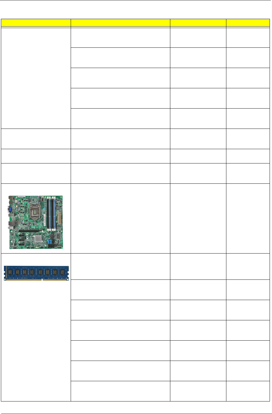
Chapter 6 89
KEYBOARD KEYBOARD 105KEY PS/2 PRIMAX
KB36111 BLACK ENGLISH/CANADIAN
FRENCH
KB KB36211 USB
105K BLACK
ENGLISH/CANAD
KB.PS20P.110
KEYBOARD 105KEY PS/2 PRIMAX
KB36111 BLACK CZECH/SLOVAK
KB KB36211 USB
105K BLACK CZECH/
SLOVAK
KB.PS20P.111
KEYBOARD 105KEY PS/2 PRIMAX
KB36111 BLACK SWISS/FR
KB KB36211 USB
105K BLACK SWISS/
FR
KB.PS20P.112
KEYBOARD 106KEY PS/2 PRIMAX
KB36111 BLACK KOREAN
KB KB36211 USB
106KS BLACK
KOREAN
KB.PS20P.113
KEYBOARD 105KEY PS/2 PRIMAX
KB36111 BLACK SPANISH LATIN
KB KB36211 USB
106KS BLACK
SPANISH LATI
KB.PS20P.114
POINTING DEVICE MOUSE PS2 PRIMAX OPTICAL
MOFGKO
MOUSE PRIMAX
OPTICAL PS2
MOFGKO
MS.11200.082
MOUSE USB LITEON SM9020B OPTICAL
NI BLACK
MOUSE SM9020B
OPTICAL NI LITEO
MS.11200.074
MOUSE USB A1B PRIMAX MOF9UO
BLACK COLOR
MOUSE USB A1B
MOF9UO BLACK
COLOR PRIMAX
MS.11200.079
MAINBOARD MAINBOARD KIT ASERENA FOR M3
INTEL H67 INTEL 82579V ACER LOGO
UATX W/O 1394 LF W/O USB3.0 W/IO
SHIELD
MB KIT ASERENA
INTEL H67 WST
MB.SFD01.002
MEMORY MEMORY A-DATA UNB-DIMM DDRIII
1333 1GB AD63I1A0823EU LF 128*8
0.065UM
DIMM 1G
AD63I1A0823EU
DDR3 1333MHZ
UNB.
KN.1GB0C.010
MEMORY APACER DDR3 1333MHZ 1G
UNB-DIMM GU502203EP0201 LF 128*8
0.065UM
DIMM 1G
75.073C1.G02 DDR3
1333MHZ
KN.1GB01.031
MEMORY KINGSTON DDR3 1333MHZ
1G ACR128X64D3U1333C9
DIMM 1G
ACR128X64D3U1333
C9
KN.1GB07.002
MEMORY DDR3 1333MHZ 1G
UNBUFFERED DIMM W/O ECC F DIE
(46NM)
DIMM 1G
M378B2873FHS-CH9
KN.1GB0B.036
MEMORY UNIFOSA DDR3 1333MHZ 1G
UNB-DIMM GU502203EP0201 LF 128*8
0.065UM
DIMM 1G
GU502203EP0201
UNB.
KN.1GB0H.015
MEMORY APACER DDR3 1333MHZ 2G
UNBUFFERED DIMM W/O ECC
DIMM 2G
75.A73C1.G02 DDR3
1333MHZ
KN.2GB01.025
MEMORY NANYA UNB-DIMM DDRIII
1333 2GB NT2GC64B88B0NF-CG LF
256*8 0.055UM
DIMM 2G
NT2GC64B88B0NF-
CG DDR3 UNB.
KN.2GB03.022
Category Part Name Description Acer Part No.
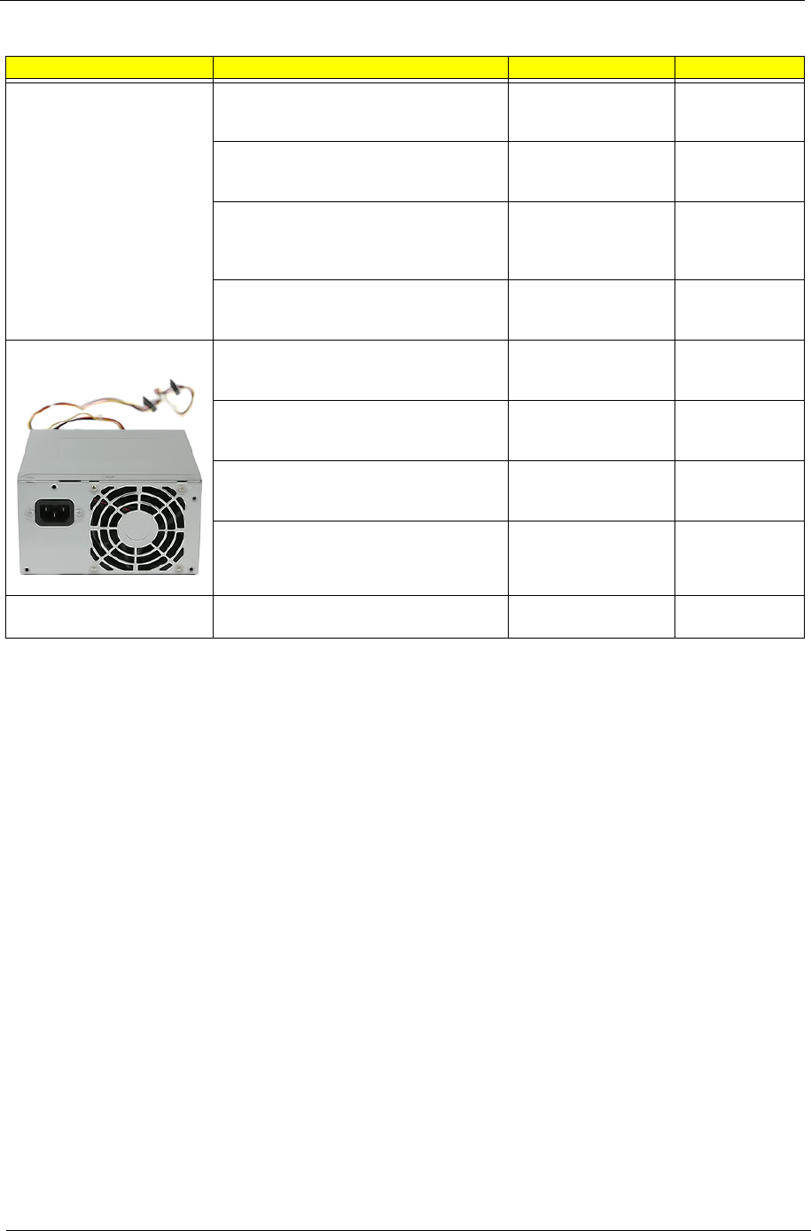
90 Chapter 6
MEMORY MEMORY KINGSTON DDR3 1333MHZ
2G UNB ACR256X64D3U1333C9
DIMM 2G
ACR256X64D3U1333
C9
KN.2GB07.002
MEMORY SAMSUNG DDR3 1333MHZ 2G
UNB DIMM W/O ECC W/2G CHIP C
DIE(46NM)
DIMM 2G
M378B5773CH0-CH9
UNB. DDR3
KN.2GB0B.029
MEMORY ADATA DDR3 1333MHZ 2G
UNB DIMM W/O ECC W/ELPIDA CHIP
DIMM 2G
AD63I1B1624EU
DDR3 1333MHZ
UNB.
KN.2GB0C.007
MEMORY UNIFOSA DDR3 1333MHZ 2G
UNB-DIMM GU512303EP0202 LF 128*8
0.065UM
DIMM 2G
GU512303EP0202
UNB.
KN.2GB0H.009
POWER SUPPLY POWER SUPPLY FSP FSP300-60EP
300W ACTIVE PFC A01005 100-127V/
220V-240V 4SATA1PATA CO-MODULE
SPS FR 300W (30L)
EUP 82+ FSP300-
60EP(1)
PY.30008.033
POWER SUPPLY DELTA DPS-300AB-57A
300W ACTIVE PFC 100-127V/220V-240V
SPS DELTA FR 300W
30L 82+ EUP DPS-
300A
PY.30009.021
POWER SUPPLY FSP FSP300-60THA
300W NONE PFC A01003 100-127V/220-
240V 4SATA1PATA CO-MODULE
SPS NON-PFC 300W
(30L) EUP FSP300-
60THA(
PY.30008.032
POWER SUPPLY LITE-ON PS-6301-08A3
300W NONE PFC 100-127V/220-240V
SPS LITEON NPFC
300W 30L EUP PS-
6301-08A
PY.3000B.016
SPEAKER SPEAKER CHIAMAW 9M-20A200-000
ACER LOGO LF 0810
SPEAKER ACER
LOGO/LF0810
SP.10600.011
Category Part Name Description Acer Part No.
