Aclara Power Line Systems Y70080-1 2.4 GHz ZigBee module User Manual ZigBee
Aclara Power-Line Systems Inc. 2.4 GHz ZigBee module ZigBee
User Manual

HAN ZigBee™ Module 1
HAN Z
IG
B
EE
M
ODULE
The HAN ZigBee® Module connects to, and is powered by a host device, but
contains its own processor, RF circuitry, and integral antenna. It transmits and
receives digital data, such as device status or consumption. The HAN ZigBee
Module is designed to be a universal solution for adding RF capability to a variety
of Aclara Intelligent End Devices (IEDs).
The Ember EM260 radio IC in the HAN ZigBee Module utilizes the IEEE
802.15.4 physical layer protocol for the 2.4 GHz Industrial, Scientific and Medical
(ISM) radio band. This protocol provides for 16 channels at 5 MHz intervals
within the 2405 MHz to 2480 MHz range. Modulation is accomplished by Offset
Quadrature Phase Shift Keying (OQPSK), and no subcarrier is used.
The HAN ZigBee Module transmits data at a rate of 250 kilobits per second, with
an occupied bandwidth of 2 MHz, and a carrier frequency stability of ± 40 ppm (98
kHz for a 2450 MHz carrier frequency).
A voltage regulator on the HAN ZigBee Module controls the PA IC supply
voltage, and consequently, the transmitter output power. This regulator is
calibrated and set at the time of manufacture.
In accordance with the FCC antenna requirements of section 15.203 and 15.204(c),
the HAN ZigBee Module shall not be used with any antenna aside from the
approved internal antenna installed at the time of production. Likewise, the HAN
ZigBee Module is not to be co-located or used in conjunction with any other
antenna or transmitter.
The HAN ZigBee Module is not intended for, and shall not be used in a handheld
or body worn device. The installation of the HAN ZigBee Module must provide a
minimum of 20 centimeters separation between the module and the body of the
user during normal operating conditions.
The PIC24FJ256 microchip controller controls the transmission or reception mode
and channel selection of the radio. It also serves as the data transfer interface
between the radio chip and the outside device in which the HAN ZigBee module is
installed. The PIC implements the network layer protocol used with the 802.15.4
PHY layer. This network layer may either be the ZigBee protocol or a proprietary
network protocol.
R
EGULATORY
D
ATA
This equipment has been tested and found to comply with the limits for a Class
B digital device, pursuant to Part 15 of the FCC Rules. These limits are
designed to provide reasonable protection against harmful interference in a
residential installation. This equipment generates, uses and can radiate radio
frequency energy and, if not installed and used in accordance with the
instructions, may cause harmful interference to radio communications.
However, there is no guarantee that interference will not occur in a particular
installation. If this equipment does cause harmful interference to radio or
television reception, which can be determined by turning the equipment off
2HAN ZigBee™ Module
and on, the user is encouraged to try to correct the interference by one or
more of the following measures:
•reorient or relocate the receiving antenna
•increase the separation between the equipment and receiver
•connect the equipment into an output on a circuit different from that to
which the receiver is connected
•consult the dealer or an experienced radio/TV technician for help
Operation is subject to the following two conditions: (1) This device may not
cause harmful interference, and (2) this device must accept any interference
received, including interference that may cause undesired operation. Changes
not expressly approved by Aclara, could void the user’s authority to operate
the equipment.
This product complies with FCC OET Bulletin 65 radiation exposure limits set
forth for an uncontrolled environment.
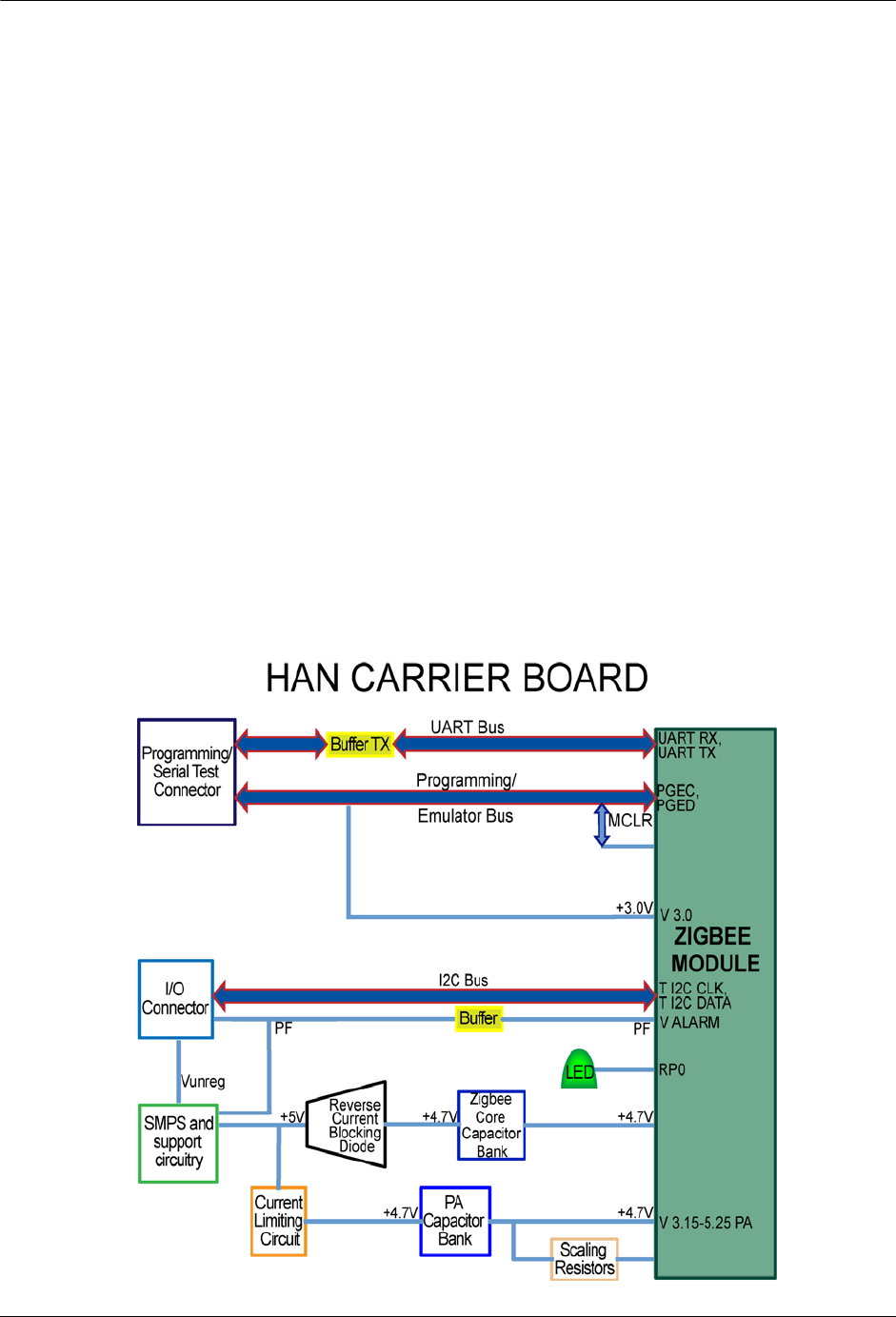
The following block diagram summarizes the interfaces and communications
between the system components.
Figure 1.1
Block diagram

HAN ZigBee™ Module 3
S
PECIFICATIONS
The HAN ZigBee® Module was designed in accordance with the IEEE 802.15.4
protocol. This section contains general, electrical, environmental, and physical
specifications for the HAN ZigBee Module.
Electrical Specifications
Compliance Specifications
N
OTE
Unless otherwise indicated, ANSI C12.1-2001 is the referring standard for tests
listed in tables Table 1.2, Table 1.3, and Table 1.4.
N
OTE
Per Measurement Canada, Specifications/Standards LMG-EG-07 & PS-E-09-E
are used to verify compliance with Canadian criteria.
Environmental Specifications
Table 1.1
HAN ZigBee Module Electrical ratings
Parameter Rating
Input Voltage 3.3 - 5V DC
Quiescent Power < 50 mW
Current while transmitting RF 210 mA
Power Supply DC energy is provided by the host.
Table 1.2
HAN ZigBee Module Compliance specifications
Test Title Applicable Specification
EMI/RFI Emission
Conducted/Radiated CFR 47 Part 15, Class B. (See also ANSI C63.4).
Test No. 27
Effect of External Magnetic Field Test No. 18
Occupied Bandwidth 2 MHz
RF Output Power 100 mW, +20 dBm or less. Meets FCC section
15.247 for field strength of emissions.
Carrier Frequency Stability Carrier frequency is crystal controlled. Accuracy is ±
40 ppm or about ± 98 kHz.
Table 1.3
HAN ZigBee Module Environmental specifications
Thermal
Effect of Operating Temperature Test No. 30 (-40°C - + 70°C)
Humidity
Effect of Relative Humidity Test No. 31 (60°C, 95% non-condensing)
4HAN ZigBee™ Module
Physical Specifications
Physical Specifications
Additional Regulatory Data
Table 1.4
HAN ZigBee Module Physical specifications
Parameter Specification
Approximate Weight < 1.0 oz. (28.3 g.)
Dimensions (Diameter & Total
Length) 0.9" x 1.5"
Table 1.5
HAN ZigBee Module Labeling requirements
Labeling Requirements
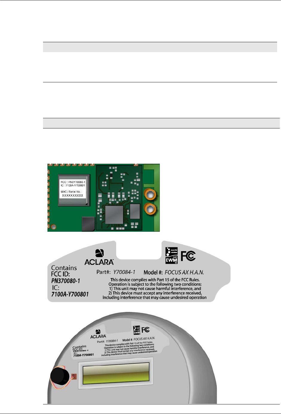
The FCC ID and IC ID numbers are located on the module label as shown in
Figure 1.1. The Aclara serial number, which is also the MAC address, is also
displayed on this label. The label shown in Figure 1.2 must be affixed to the
exterior of the host device as shown in
Figure 1.1
HAN ZigBee Module label
Example of label as it appears on module.
Refer to Drawing Y70122-1-DWG for
actual label image.
Figure 1.2
Host device label
Figure 1.3
Exterior HAN Module label

HAN ZigBee™ Module 5
Chapter 1 • Specifications
The following is a tabulation of regulatory data found elsewhere in this manual and
is required by the regulatory agencies of some countries.
N
OTE
No subcarrier is used to modulate the carrier. Refer to paragraph 2, on page 1
for more information.
Table 1.6
HAN ZigBee Regulatory Data
Parameter Specification
Disclaimer noting that operation of the
device is subject to conditions and that the
device may not cause harmful interference
and device must accept any interference
received.
Regulatory Data note on page 1.
Principles of device operation HAN ZigBee Module on page 1
Block diagram Block diagram on page 2
Operating frequency 2400 - 2483.5 MHz,
Channeling 16 channels
Mode of transmission Narrow Band FSK
Internal/External data source External;
Type(s) of modulation OQPSK (Offset quadrature phase-shift
keying);
Subcarrier modulation No.
Type of information transmitted Equipment control
Occupied bandwidth 2 MHz,
RF output power 100 mW, +20 dBm or less. Meets FCC
section 15.247 for field strength emissions
Carrier frequency stability Crystal controlled, ± 40 ppm or ± 98 kHz,

6HAN ZigBee™ Module
Additional Regulatory Data