Aclara Power Line Systems Y72572-1 Residential Metering Transponder User Manual UMT C KV User Guide
Aclara Power-Line Systems Inc. Residential Metering Transponder UMT C KV User Guide
User Manual
UNIVERSAL METERING
TRANSPONDER FOR kV2c METER
USER GUIDE Y10577-TUM REV C

Universal Metering Transponder for kV2c™ Meter User Guide ( Y10577-TUM Rev C)
Proprietary Notice
Information contained in this document is private to Distribution Control Systems, Inc., St. Louis, Missouri (DCSI).
This information may not be published, reproduced, or otherwise disseminated without the express written
authorization of DCSI.
Any software or firmware described in this document is furnished under a license and may be used or copied only in
accordance with the terms of such license.
Disclaimer
The information in this document is subject to change without notice and should not be construed as a commitment
by DCSI. DCSI assumes no responsibility for any errors that may appear in this document.
No responsibility is assumed for the use or reliability of software on equipment that is not supplied by DCSI.
TWACS, the TWACS logo, and the DCSI logo are registered trademarks of Distribution Control Systems, Inc., St.
Louis, Mo. All other registered trademarks are property of their respective owners.
TWACS®
Two-Way Automatic Communication System,
a product of
Distribution Control Systems, Inc.
Confidential and Proprietary
Copyright 2006, 2007. All Rights Reserved.

Universal Metering Transponder for kV2c™ Meter User Guide i
Figures and Tables iii
Chapter 1: Introduction 1
Safety Warnings and Symbols . . . . . . . . . . . . . . . . . . . . . . . 2
Support . . . . . . . . . . . . . . . . . . . . . . . . . . . . . . . . . 3
Product Returns . . . . . . . . . . . . . . . . . . . . . . . . . . . . . 3
Related Documentation. . . . . . . . . . . . . . . . . . . . . . . . . . 4
Let Us Know How We’re Doing. . . . . . . . . . . . . . . . . . . . . . . 5
TWACS System Overview . . . . . . . . . . . . . . . . . . . . . . . . . 6
Chapter 2: Functional Description 9
Time Synchronization . . . . . . . . . . . . . . . . . . . . . . . . . . 9
Daylight Saving Time . . . . . . . . . . . . . . . . . . . . . . . . . . 10
Universal Metering Transponder (UMT-C-KV) . . . . . . . . . . . . . . . . 10
Functional Description of the UMT-C-KV . . . . . . . . . . . . . . . . . . 11
Primary Functions. . . . . . . . . . . . . . . . . . . . . . . . . . . . 13
Communication. . . . . . . . . . . . . . . . . . . . . . . . . . . . 13
Data Retrieval . . . . . . . . . . . . . . . . . . . . . . . . . . . . 17
Loss of Power Handling . . . . . . . . . . . . . . . . . . . . . . . . . 18
AC Input Voltage Tolerance Characteristics . . . . . . . . . . . . . . . 18
Outage Duration Monitoring . . . . . . . . . . . . . . . . . . . . . . 19
Power Down . . . . . . . . . . . . . . . . . . . . . . . . . . . . . 20
Power Reliability Indices. . . . . . . . . . . . . . . . . . . . . . . . 21
Energy and Demand Measurement . . . . . . . . . . . . . . . . . . . . 22
Total Consumption Present . . . . . . . . . . . . . . . . . . . . . . 22
Meter Constants . . . . . . . . . . . . . . . . . . . . . . . . . . . 23
Demand Measurement. . . . . . . . . . . . . . . . . . . . . . . . . 23
Interval Data . . . . . . . . . . . . . . . . . . . . . . . . . . . . . . 24
Additional Features . . . . . . . . . . . . . . . . . . . . . . . . . . . 25
Configuration Monitoring . . . . . . . . . . . . . . . . . . . . . . . 25
Installation With Instrument Transformers. . . . . . . . . . . . . . . . 25
Tamper Detection. . . . . . . . . . . . . . . . . . . . . . . . . . . 25
Reverse Rotation . . . . . . . . . . . . . . . . . . . . . . . . . . . 25
No Consumption . . . . . . . . . . . . . . . . . . . . . . . . . . . 25
Voltage Agility . . . . . . . . . . . . . . . . . . . . . . . . . . . . 26
Voltage Monitoring . . . . . . . . . . . . . . . . . . . . . . . . . . 26
EMTR-3-KV Interface (Multiport Capability) . . . . . . . . . . . . . . . 26
On-Request Reads. . . . . . . . . . . . . . . . . . . . . . . . . . . 28
Temperature Monitoring. . . . . . . . . . . . . . . . . . . . . . . . 29
Historical Data . . . . . . . . . . . . . . . . . . . . . . . . . . . . 29
480 Volt Applications . . . . . . . . . . . . . . . . . . . . . . . . . 29
Calibration Testing . . . . . . . . . . . . . . . . . . . . . . . . . . 29
Options . . . . . . . . . . . . . . . . . . . . . . . . . . . . . . . . 30
TWACS Installation . . . . . . . . . . . . . . . . . . . . . . . . . . . . 30
Type and Model Numbers . . . . . . . . . . . . . . . . . . . . . . . . 30
Voltage Transformer (VT) Connected Meter/Transponder . . . . . . . . . . 31
Verification of Equipment . . . . . . . . . . . . . . . . . . . . . . . 32
Table of Contents

ii Universal Metering Transponder for kV2c™ Meter User Guide
Table of Contents
Installation Procedure . . . . . . . . . . . . . . . . . . . . . . . . . . 32
Registers. . . . . . . . . . . . . . . . . . . . . . . . . . . . . . . 33
Thermal Limit . . . . . . . . . . . . . . . . . . . . . . . . . . . . 33
Changing the Sequence Delay . . . . . . . . . . . . . . . . . . . . . 34
Chapter 3: Troubleshooting 35
Performing Remote Analysis (TNS) . . . . . . . . . . . . . . . . . . . . . 35
Performing Remote Analysis (TWACS NG) . . . . . . . . . . . . . . . . . . 37
Field Troubleshooting. . . . . . . . . . . . . . . . . . . . . . . . . . . 38
Meter Shop Test System. . . . . . . . . . . . . . . . . . . . . . . . . . 39
Chapter 4: Specifications 41
Electrical Specifications . . . . . . . . . . . . . . . . . . . . . . . . . 41
Compliance Specifications . . . . . . . . . . . . . . . . . . . . . . . . 41
Environmental Specifications . . . . . . . . . . . . . . . . . . . . . . . 42
Physical Specifications . . . . . . . . . . . . . . . . . . . . . . . . . . 43
Additional Regulatory Data . . . . . . . . . . . . . . . . . . . . . . . . 44
Acronyms 45
Glossary 47
Index 51

Universal Metering Transponder for kV2c™ Meter User Guide iii
Figure 1.1 TWACS system . . . . . . . . . . . . . . . . . . . . . . . . . . . . . . . . . . . .7
Figure 2.1 UMT-C-KV module assembly. . . . . . . . . . . . . . . . . . . . . . . . . . .10
Figure 2.2 View of UMT-C-KV module integrated within the kV2c meter. . . . . 11
Figure 2.3 Block diagram of the UMT-C-KV 2.0. . . . . . . . . . . . . . . . . . . . . .12
Table 2.1 Explanations for block diagram components . . . . . . . . . . . . . . . .12
Table 2.2 Addresses and address modes . . . . . . . . . . . . . . . . . . . . . . . . .15
Table 2.3 Supported TWACS system communication features . . . . . . . . . . .16
Table 2.4 Metered quantities . . . . . . . . . . . . . . . . . . . . . . . . . . . . . . . .18
Table 2.5 Example 35D DSID table . . . . . . . . . . . . . . . . . . . . . . . . . . . . .19
Table 2.6 Meter Map and Meter Data Registers . . . . . . . . . . . . . . . . . . . . .22
Table 2.7 Sample data storage days . . . . . . . . . . . . . . . . . . . . . . . . . . . .24
Figure 2.4 RF operation block diagram. . . . . . . . . . . . . . . . . . . . . . . . . . .27
Table 2.8 Model number, class, meter form, voltage, service type,
and energy. . . . . . . . . . . . . . . . . . . . . . . . . . . . . . . . . . . . . .30
Figure 2.5 Meter nameplate. . . . . . . . . . . . . . . . . . . . . . . . . . . . . . . . . .32
Figure 3.1 Optical port connection for kV2c meter. . . . . . . . . . . . . . . . . . .40
Figure 3.2 SIA cable assembly for kV2c meter . . . . . . . . . . . . . . . . . . . . . .40
Table 4.1 Electrical ratings. . . . . . . . . . . . . . . . . . . . . . . . . . . . . . . . . .41
Table 4.2 Compliance specifications. . . . . . . . . . . . . . . . . . . . . . . . . . . .41
Table 4.3 Environmental specifications. . . . . . . . . . . . . . . . . . . . . . . . . .42
Table 4.4 Physical specifications . . . . . . . . . . . . . . . . . . . . . . . . . . . . . .43
Figures and Tables

iv Universal Metering Transponder for kV2c™ Meter User Guide
Figures and Tables

Universal Metering Transponder for kV2c™ Meter User Guide 1
CHAPTER
1
I
NTRODUCTION
This chapter contains general information about this manual, important safety
warnings to observe when using this product, contact information to receive
support, and an overview of the TWACS system.
2Universal Metering Transponder for kV2c™ Meter User Guide
Safety Warnings and Symbols
Safety Warnings and Symbols
The following symbols are used in this manual.
Symbols and Warnings
WARNING: Indicate a risk of injury, possible death, and equipment
damage.
WARNING: Indicates a risk of electric shock, causing possible injury,
death, and equipment damage.

Universal Metering Transponder for kV2c™ Meter User Guide 3
Chapter 1 • Introduction
Support
The TWACS Portal (https://portal.twacs.com/) provides a wide range of
information that can serve as a starting point when you have a question. The Portal
contains information such as:
If, at any time, you would like to speak with a DCSI representative about any
product or service or if you do not have a username and password to access the
Portal, please contact DCSI Customer Care:
Product Returns
I
MPORTANT
Before returning product to DCSI, make sure you have identified the root cause
of the problem. As needed, perform troubleshooting requesting Technical
Support through DCSI Customer Care when additional assistance is required. It
is critical to identify the root problem to avoid shipping hardware for repairs
when the problem lies elsewhere.
To return DCSI products for repair, complete the Service & Repair RMA Request
through the TWACS Portal (https://portal.twacs.com), providing as much detail
about the problem as possible. If you have any questions regarding your return,
please contact rma@twacs.com or call 1-800-892-9008 and choose the Service and
Repair option.
•User Guides •FAQs
• Service Advisories • Customer Discussion Threads
• Training Registration • Upcoming Events
• Certified Partner Information • User Group Conference Information
• Current News • The Power Line Newsletter
Email: care@twacs.com
Phone: 1-800-892-9008
Address: Distribution Control Systems, Inc.
945 Hornet Drive
Hazelwood, MO 63042
USA

4Universal Metering Transponder for kV2c™ Meter User Guide
Related Documentation
Related Documentation
The following publications are referenced in this manual. The documents listed
below plus the latest version of all other DCSI technical publications are available
through the TWACS Portal (https://portal.twacs.com/).
Meter Shop Test System Help
Provides all the necessary details required for testing TWACS-enabled devices
with the Meter Shop Test Tool software. Access the Help through the Meter Shop
Test Tool software interface. The Help is not available through the TWACS
Portal.
Meter Shop Test System Set-Up Guide (Y10030TM)
Provides information that enables you to test TWACS-enabled devices for
TWACS signaling response, read select transponder registers, zero select
transponder registers, and perform various other transponder functions.
Portable RCE Test Unit Technical Manual (Y103127-3TM)
Ships with the Portable RCE Test Unit. Includes detailed product specifications
and operating instructions.
TNS End User Guide (Y10285TM)
Serves as a companion manual to the TNS Operational Process Guide. While the
TNS Operational Process Guide provides high-level process and procedure
recommendations for obtaining optimum results from your TWACS system, the
TNS End User Guide provides the detailed procedures, and form field and
application definitions, that enable you to perform the functions found in the
process manual.
TNS Operational Process Guide (Y10352TM)
Presents high-level procedures and processes for operating your TWACS system,
through the TNS interface. These processes and procedures span a number of
application sets, and are organized around functions such as reading meters,
substation setup, and operating TNS.
Transponder Type and Model Matrix (Y10598-TEB)
Provides a listing of transponders, transponder types, and applicable meter
models.
TWACS® Network Gateway Operational Process Guide (Y10433-TUM-NGT)
Includes procedures and processes for operating your TWACS system through
the TWACS® NG interface. The information spans a number of application sets,
and are organized around functions such as reading meters, substation setup, and
operating TWACS NG.

Universal Metering Transponder for kV2c™ Meter User Guide 5
Chapter 1 • Introduction
TWACS® NG System Help
Built into the TWACS® NG interface, topic and index-searchable online system
help is available. Access the Help through the software interface. The Help is not
available through the TWACS Portal.
TWACS® - ORION® for UMT Products User Guide (Y20100-TUM)
Provides a brief overview of the TWACS-ORION system, explains how the
TWACS-ORION system interfaces with the TWACS system, and describes the
functions of the EMTR-3, HHTR-3, and ORION transmitter.
UMT-C-KV Field Installation Instructions (Y73111-3)
Presents field installation diagrams for all meter forms supported by the
transponder.
Let Us Know How We’re Doing
In an ongoing effort to produce effective documentation, the Technical
Publications department at DCSI welcomes any feedback you can offer regarding
this manual.
Please relay feedback, including suggestions for improvement or to alert us to
corrections, by sending an email to techpubs@twacs.com or calling Customer
Care at 1-800-892-9008.

6Universal Metering Transponder for kV2c™ Meter User Guide
TWACS System Overview
TWACS System Overview
The TWACS system is a fixed network, utility communication system. Running at
a centralized location, the TWACS operating software communicates with end
points, such as meters, by way of existing power lines. The TWACS system allows
full two-way access to and from the consumer’s meter, providing communication
and control features for the Utility.
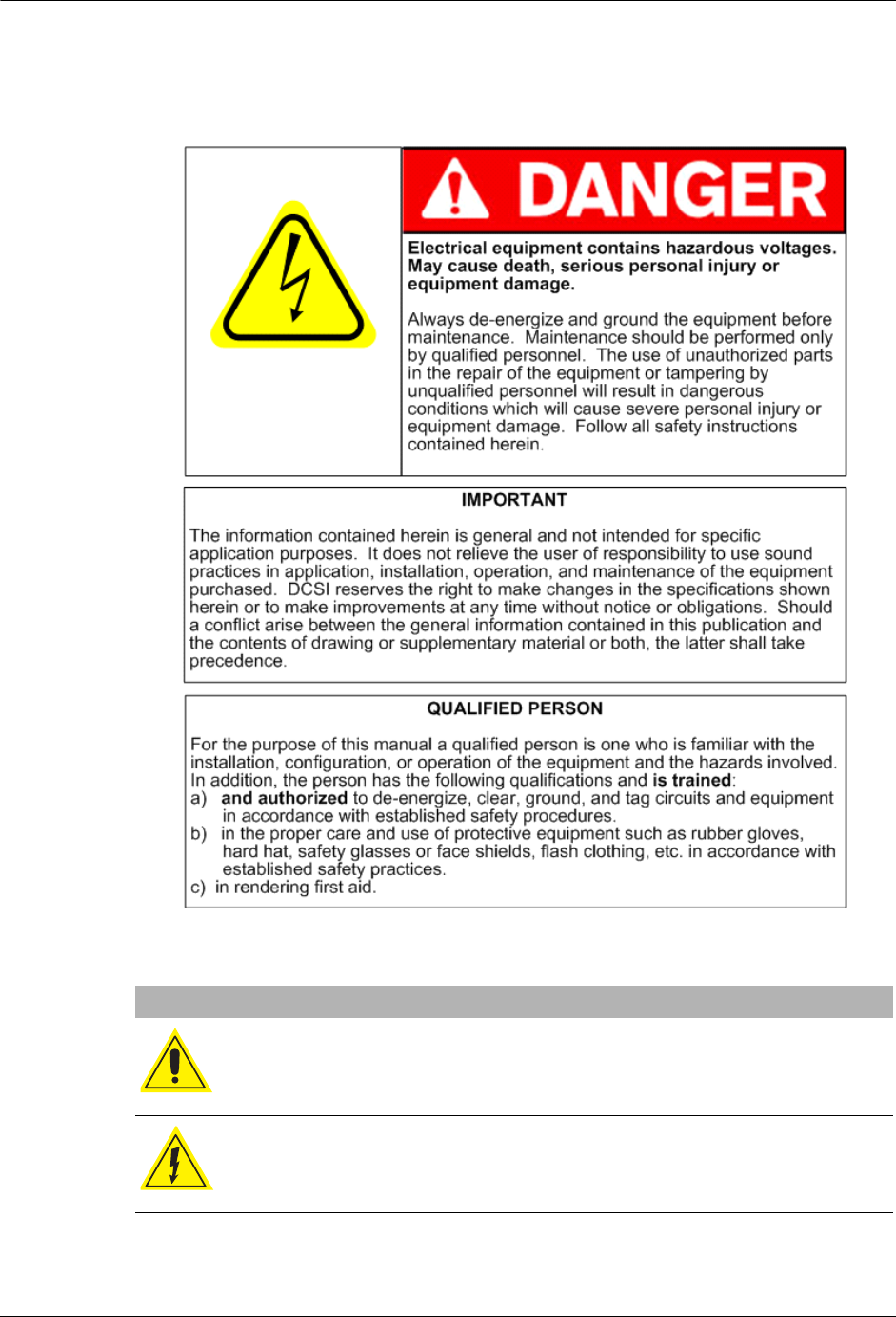
The TWACS system consists of three levels of components (see Figure 1.1):
• Master Station (MS)
The Master Station TWACS operating software, either TWACS Net Server
(TNS) or TWACS® Network Gateway (TWACS NG), is the chief
component of the entire Two-Way Automatic Communication System
(TWACS). The Master Station software manages all collected metering and
interval data as well as the connection between the utility and the consumer’s
premises. TNS is DCSI’s standard solution while TWACS NG is available
for very large deployments requiring a high volume of readings for
time-of-use or critical peak pricing programs.
The primary functions of TNS and TWACS NG are:
•Managing the TWACS system communication network.
•Supporting applications such as metering, troubleshooting, outage
detection, and load control.
•Collecting remote meter data for the database server, which forwards the
data to a third-party utility software application.
TNS and TWACS NG are part of the corporate enterprise network. The
system is based on the Oracle® database, which is an open system, meaning
it can interact and inter-operate with other applications on local and remote
systems, on a variety of hardware platforms, and in a number of software
environments. The system provides the user interfaces for configuring the
necessary parameters to retrieve and send data.
• Substation Communications Equipment (SCE)
• Remote Communications Equipment (RCE)
This is the level at which the meter transponder resides within the electric
meter.
As shown in Figure 1.1, outbound messages originate in the Master Station and
pass through the substation to the transponder (RCE). Inbound meter data is sent
from the transponder to the SCE, where it is decoded and then sent to the Master
Station for analysis or bill file creation.
Universal Metering Transponder for kV2c™ Meter User Guide 7
Chapter 1 • Introduction
Figure 1.1
TWACS system

8Universal Metering Transponder for kV2c™ Meter User Guide
TWACS System Overview

Universal Metering Transponder for kV2c™ Meter User Guide 9
CHAPTER
2
F
UNCTIONAL
D
ESCRIPTION
This chapter provides an overview of the TWACS® system, explains how the
Universal Metering Transponder for the GE kV2c meter (UMT-C-KV MP)
interfaces with the TWACS system, and describes the functions of the transponder.
This user guide provides feature and functionality information for Firmware
version 2.00. Enhancements since version 1.20 include, but are not limited to:
• Addition of EMTR-3-KV interface (multiport)
• New module type number - 101
The kV2c meter may hereafter be referred to as kV2c, kV2c meter, or meter.
UMT, UMT-C-KV, transponder, and module refer to the DCSI UMT-C-KV MP.
Time Synchronization
The Master Station is synchronized to an official US reference atomic time clock.
The Master Station sets the time in each of the SCEs, and the SCE broadcasts the
time to all the RCEs. TWACS communication introduces a fixed time difference
(offset) between the Master Station clock and the RCE master clock.
In addition, a free running Real-Time-Clock (RTC) is provided in the UMT-C-KV
as an alternate time base for maintaining the time when the RCE experiences a
power down or an interruption. The RTC maintains the RCE time (during an
outage) for a period of no less than 24 hours. This RTC is a Secondary Time Base
for the RCE and is accurate to within 17.5 seconds per day. The RCE uses the RTC
time for time-stamping an event when the power is restored. It also maintains all
timing functions until the RCE is again in time sync with the SCE transmitted time
sync signal. Each time the RCE hears the time sync broadcast, it compares its
master clock time with the SCE time. If the offset between SCE time and the
master clock time does not exceed the threshold limits (± 15 seconds), they are
considered to be operating in synchronization.
The UMT-C-KV internal Serial Date and Serial Time registers are volatile and are
initialized at power-up. The UMT-C-KV updates its Serial Date & Time registers
when it receives the Set RCE Date/Time command. The Set RCE Date/Time
command, normally sent every fifteen minutes from the CCE to the SCE,
synchronizes the SCE clock to the CCE clock. To update serial date and time, the
SCE sends the Set Date/Time command automatically to the UMT-C-KV.
Certain UMT-C-KV functions are not performed if the Serial Time is invalid.
TWACS uses Serial Time Units (STU) as measures of time. Each STU equals 2.5
seconds, with midnight equal to zero.
10 Universal Metering Transponder for kV2c™ Meter User Guide
Daylight Saving Time
The UMT-C-KV does not support the bi-annual Daylight Saving Time (DST)
change as a scheduled routine. However, when the Master Station transmits a time
sync command after the DST change has occurred, the RCE recognizes an offset
exceeding the threshold limits (offset of one hour ± 15 seconds versus the 15
second threshold). The RCE master clock time is updated automatically. Whenever
the RCE master clock time is corrected to implement daylight saving time, one
hour of data is lost on the 23 and 25 hour days, and the corresponding hour bins are
marked as invalid.
Instructions for updating your TNS system for the Daylight Saving time
adjustment are in the TNS Operational Process Guide.
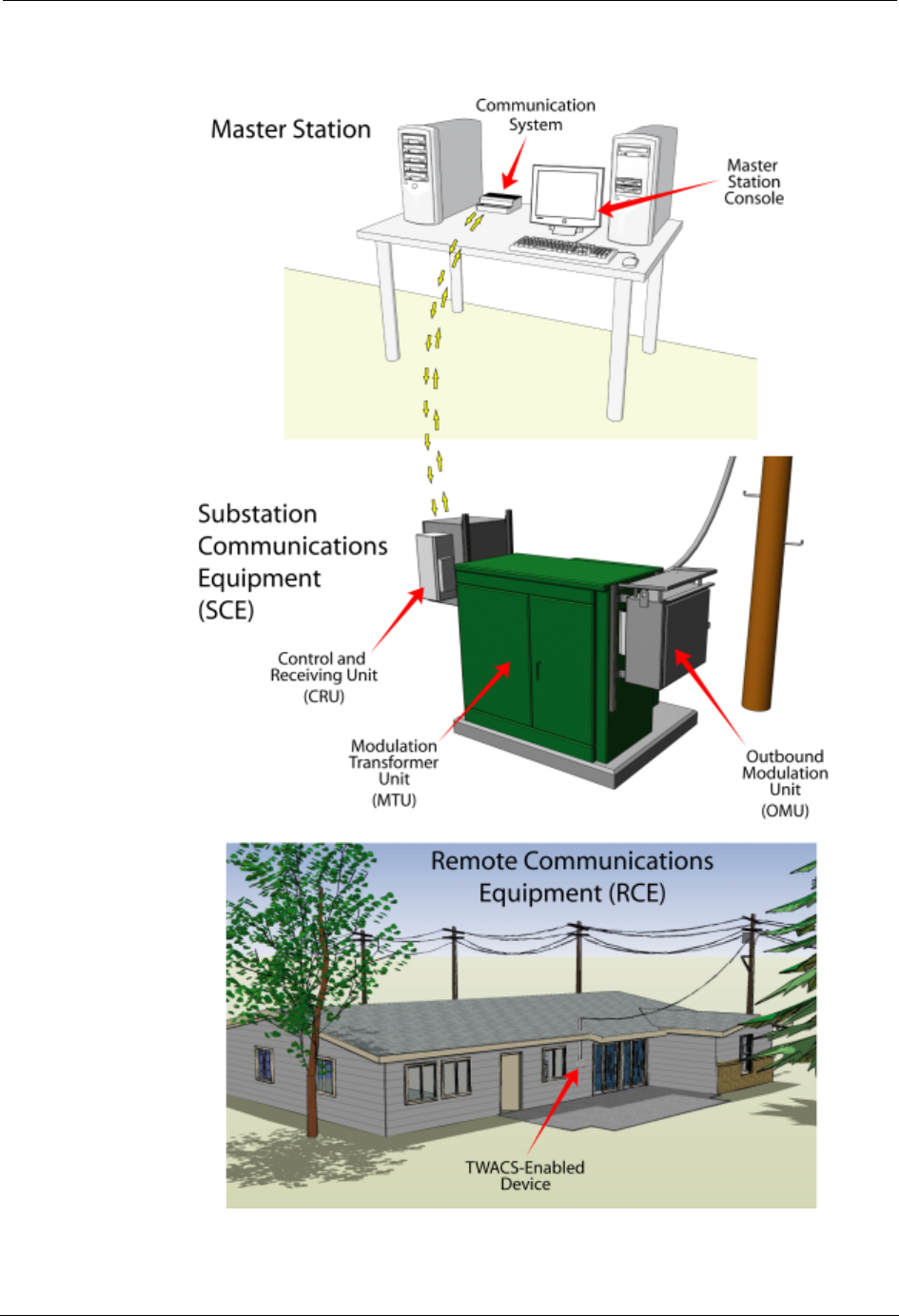
Universal Metering Transponder (UMT-C-KV)
The Universal Metering Transponder (UMT-C-KV) is a remote power-line
communication transponder contained within and interfaced to a kV2c meter. The
UMT-C-KV integrates a single or polyphase meter with TWACS. The
UMT-C-KV can be integrated with kV2c meters of various forms and classes. See
Table 2.8 on page 30.
AC power enters the kV2c meter from the Utility supply. The UMT-C-KV
receives operating DC power from the kV2c meter and communicates with the
meter through a multiconductor ribbon cable. Communication between the
UMT-C-KV and the utility company is provided by TWACS across the Utility
power lines.
Figure 2.1
UMT-C-KV module assembly
Universal Metering Transponder for kV2c™ Meter User Guide 11
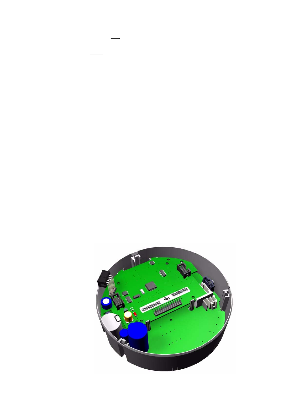
Chapter 2 • Functional Description
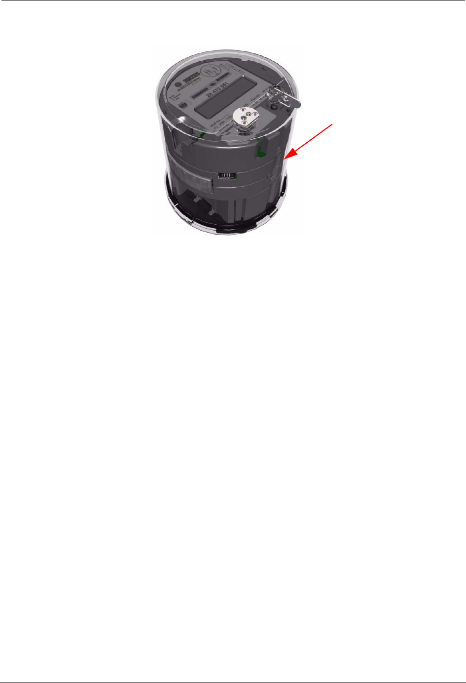
Figure 2.2
View of UMT-C-KV module integrated within the kV2c meter
Functional Description of the UMT-C-KV
The UMT-C-KV acts as an interface between the kV2c meter and TWACS
powerline communication technology. It facilitates communication of kV2c meter
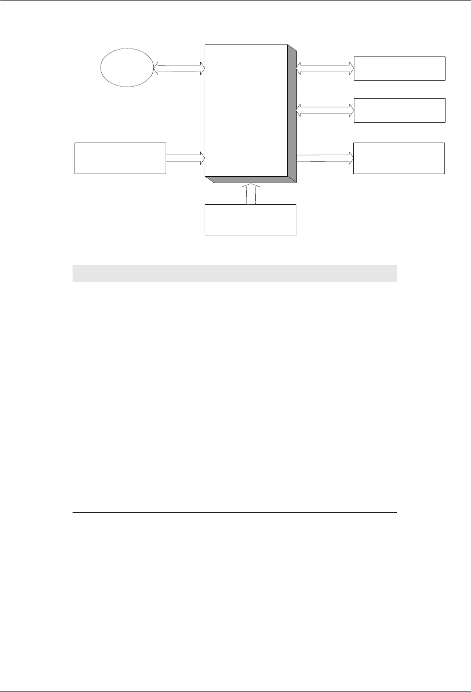
quantities over the utility company distribution power lines. The diagram in Figure
2.3, “Block diagram of the UMT-C-KV 2.0”, illustrates the functionality of the
UMT-C-KV. Table 2.1 explains the block diagram components.
UMT-C-KV
Module
12 Universal Metering Transponder for kV2c™ Meter User Guide
Functional Description of the UMT-C-KV
Figure 2.3
Block diagram of the UMT-C-KV 2.0
The kV2c meter is plugged into an American National Standards Institute (ANSI)
industry standard meter socket. All UMT-C-KV models can perform five minute
reads of voltage values. A choice between 60-, 30-, 15-, 10-, or 5-minute interval
electric metering is available. 32 registers from the kV2c meter can be mapped to
the transponder. Six of these data values are pre-defined in the transponder.
Table 2.1
Explanations for block diagram components
Component Definition
TWACS UMT-C-KV
microprocessor Processes all inputs and generates and
controls transmission of outputs
Power loss detection UMT-C-KV response facilitates orderly
shutdown and saving of important data when
AC power is not adequate for operation
kV2c Meter Provides metering data to the UMT-C-KV
via serial communications
TWACS outbound
detection circuitry Monitors the AC power for TWACS
outbound signal
Serial port - test Used to perform initial programming
Non-volatile memory Preserves register data during power outages
TWACS inbound
generation circuitry Generates TWACS inbound messages at the
UMT-C-KV, which are transmitted to the
SCE
EMTR-3-KV Electric Meter Transceiver-3. Serves as the
gateway to the TWACS network for the
remote RF water, gas, or propane meters.
TWACS
UMT-C-KV
Microcontroller
SERIAL PORT
(TEST)
NONVOLATILE
MEMORY
GE
kV2c/c+
Meter
SERIAL
LINK
POWER
LOSS
DETECTION
TWACS
OUTBOUND
DETECTION
CIRCUITRY
TWACS INBOUND
GENERATION
CIRCUITRY
EMTR-3-KV

Universal Metering Transponder for kV2c™ Meter User Guide 13
Chapter 2 • Functional Description
Primary Functions
The UMT-C-KV has two primary functions:
• Communication - receive TWACS outbound commands and generate
TWACS inbound responses.
• Data retrieval - from customer-selected kV2c meter registers configured at
meter/transponder integration.
Each of these functions is described in the following sections and is graphically
represented in Figure 2.3.
Communication
The UMT-C-KV communication process is described in the following sections.
Meter Interface
The UMT-C-KV performs the interface function of connecting a kV2c electric
meter to TWACS. It interfaces with the meter’s communication port and to the
power line using TWACS communication technology.
The UMT-C-KV uses TWACS technology to communicate from the meter, to the
SCE, to the utility company over the power distribution lines. The
outbound/inbound synchronization techniques allow detection of one outbound
command at a time. When a command is detected, the UMT-C-KV either
completes two-way command processing and transmits the inbound response
before outbound detection resumes, or, the UMT-C-KV completes one-way
command processing before outbound detection resumes.
Serial Number Address
The serial number address is the unique, fixed address present in every
UMT-C-KV. It is assigned at the factory and can be written using the Serial
Communication Port. It is used to address one UMT-C-KV at a time. This address
must be used during the initialization of the UMT-C-KV to assign at least the first
two-way address. Subsequently, the serial number address is optionally used for
communication to a single UMT-C-KV. The serial number address is also used
when testing the module with RCE test equipment.
Two-Way Address
Up to eight (8) two-way addresses are assigned to the UMT-C-KV in order for the
TWACS operating software and the module to communicate with each other.
N
OTE
Some features and capabilities of the transponder may not be supported, or may
be only partially supported by some versions of master station software.

14 Universal Metering Transponder for kV2c™ Meter User Guide
Functional Description of the UMT-C-KV
Two-way addresses are comprised of three fields:
• Function - operational application, e.g. outage detection. Valid range 1-63.
• Group - quantity of RCEs addressed by group. Valid range 1-262,143.
• Unit - further subdivision of Group field and specific to channeling scheme.
Valid range 1-255.
Certain restrictions are placed on the assignment of multiple addresses.
Specifically, no more than one two-way address slot in an individual UMT-C-KV
can contain the same function and group fields.
A two-way address is written to a specific address slot using a ‘Write RCE
Registers’, ‘Bulk Assign Two-way Addresses’, or ‘Initialize RCE’ command. In
order to assign a new two-way address, the contents of the address slot are simply
overwritten. A two-way address is de-assigned by writing the slot to zero.
TWACS-10 and TWACS-20 Communication Protocols
TWACS-10 and TWACS-20 communication protocols establish the method and
form that can be used to address Remote Communications Equipment. TWACS-10
and TWACS-20 capable RCEs can be addressed using TWACS-10 modes.
However, TWACS-10-only capable RCEs can not be addressed using TWACS-20
protocol modes . TWACS-10 and TWACS-20 addressing protocols are supported
by the UMT-C-KV.
Following assignment of a two-way address to the UMT-C-KV, subsequent
commands may utilize the following TWACS-10 or TWACS-20 address modes:
TWACS-10 Addressing Modes
• Serial Number (Mode 1), addressing a single module, with or without a
response
• Two-way unit (Mode 2), addressing a single module, with or without a
response
• Two-way group (Mode 3), addressing a group of up to 256 modules, with or
without a response
• One-way functional (Mode 4), addressing an unlimited number of modules,
with no response
TWACS-20 Addressing Modes
Includes all of the TWACS-10 Addressing Modes, plus the following:
• Serial Number Set (Mode 7.7), addressing ad-hoc sets with or without
response, concurrent feeders
• Function/Group/Unit Set, (Mode 7.8)addressing sets of up to 64 non
sequential units with or without response, concurrent feeders
• Function/Group Set (Mode 7.9), addressing up to 8 groups of 256 units each,
with or without response, concurrent feeders

Universal Metering Transponder for kV2c™ Meter User Guide 15
Chapter 2 • Functional Description
Two-way addresses are not associated with any particular function or port. The
three addressing modes supported by the two-way address can be used to perform
any function in the UMT-C-KV when the appropriate command parameters are
used.
The table below summarizes addresses and addressing modes supported by the
UMT-C-KV.
Table 2.2
Addresses and address modes
Addresses Available
Serial Number Supported
Two-Way Assignable Supported (8 slots)
One-Way Assignable Not Applicable
Addressing Range
Serial Number 1 to 4,294,967,295
Two-Way Assignable
Function 0 to 63
Group 0 to 262,143
Unit Number 0 to 255
TWACS-10 Addressing Modes
Serial Number (Mode 1) One-Way & Two-Way
Two-way by Unit (Mode 2) One-Way & Two-Way
Two-way by Group (Mode 3) One-Way & Two-Way
One-way Functional (Mode 4) One-Way only
TWACS-20 Addressing Modes
Serial Number Set (Mode 7.7) One-Way & Two-Way
Function/Group/Unit Set (Mode
7.8) One-Way & Two-Way
Function/Group Set (Mode 7.9) One-Way & Two-Way

16 Universal Metering Transponder for kV2c™ Meter User Guide
Functional Description of the UMT-C-KV
The table below summarizes TWACS system communication features supported
by the UMT-C-KV.
Serial Communications Using the Manufacturer's Serial Port
Communications between the UMT-C-KV Serial Port and the meter
Test/Programming Connector requires the use of Identification and Security
packets. In this mode of operation the transponder recognizes that its serial ports
are sharing the same serial communication line and will not transmit from both of
its serial ports at the same time.
Table 2.3
Supported TWACS system communication features
Response Modes - TWACS-10
Standard Inbound Header, Data (3 to 13 bytes)
Error Correction Header, Data, Hamming (4 to 14 bytes)
Fast Poll Fixed Header Only (1 byte with all indicator bits:
Alarm, Diagnostics, Tamper, and Outage, fixed at 1)
Link-Level Acknowledge Header (3 bytes)
No Response No Inbound Response (0 bytes)
Response Modes - TWACS-20
Standard (Mode 0) Header, Data (3 to 7 bytes)
Standard (Mode 1) Header, Data (4 to 14 bytes)
Standard (Mode 2) Header, Data (5 to 14 bytes)
Link-Level (Mode 4) Header (3 bytes)
Fast Poll (Mode 6) Fixed Header (1 byte)
No Response (Mode 7) No Inbound Response (0 bytes)
Standard (Mode 8) Header, Data (3 to 7 bytes)
Standard (Mode 9) Header, Data (4 to 14 bytes)
Standard (Mode 10) Header, Data (5 to 14 bytes)
Inbound Signaling
Channels 6 channels
Channel Sets Channel sets 0-5 for SCE and channel set 6 for RCE
test equipment
Time Slots 256 time slots
Message Capacity 14 bytes
Burst Capacity 22 bytes
Maximum Outbound Message Length 31 bytes
62 bytes in TWACS-20 extended length mode

Universal Metering Transponder for kV2c™ Meter User Guide 17
Chapter 2 • Functional Description
Meter Optical Port Support
N
OTE
All serial port opcodes defined for the UMT-C-KV are accessible through the
meter optical port.
Communications between the meter optical port and the UMT-C-KV
Test/Programming Serial Port begins with the transponder receiving a specified
hexadecimal Identification Packet (IP) from the meter optical port - EE 80 20 00
00 01 20 20 75. After receiving the IP from the meter optical port the UMT-C-KV
transmits an acknowledgement back to the meter optical port, verifies the
password, sends an acknowledgement to the meter, and asserts its Modem Busy
line. The transmission of the Identification Packet and Security Packet conforms
to the ANSI C12.18 communication protocol. After password acknowledgement,
all communication between the meter optical port and the transponder uses the
Gateway Serial Protocol, GATEWAY-SPEC, in ASCII at 9600 baud.
Communication between the meter optical port and the transponder continues to
follow the gateway protocol until 1.0 +/- 0.01 seconds have passed since the last
communication. After this period has passed, the Modem Busy line is de-asserted.
Password Access
A default password is supplied to the customer for optical port access to the
transponder. The transponder contains a “Bad Password Counter”. After counting
4 incorrect passwords, the transponder locks out Serial Communication between
the meter optical port and the transponder Test/Programming Serial Port for 15
minutes. At the same time, the transponder sets bit 0 of register #36,”Indicators
Tamper”. Bit 0 of register #36 remains set until cleared by TNS. The “Bad
Password Counter” is cleared if no incorrect password has been received by the
transponder within the last 15 minutes.
Data Retrieval
The UMT-C-KV reads a subset of 32 registers as selected by the utility company.
All selected data are read at power-up and every five minutes thereafter if a valid
RCE Time Synchronization command was received. See Time Synchronization on
page 9.
N
OTE
Some features and capabilities of the transponder may not be supported, or may
be only partially supported by some versions of master station software.
Consumption Metering (Wh)
The UMT-C-KV provides remote access to the energy measurement registers of
the kV2c meter. The UMT-C-KV retrieves appropriate values from the meter’s
internal ANSI Standard tables. The UMT-C-KV retrieves data from only
“programmed” kV2c registers. When requested, the UMT-C-KV can supply data
from the latest read.

18 Universal Metering Transponder for kV2c™ Meter User Guide
Functional Description of the UMT-C-KV
Time-of-Use (TOU)
The kV2c meter can perform time-of-use metering when required and programmed
accordingly. The time-of-use schedule is loaded into the meter during meter/RCE
integration. This schedule determines the times that the different TOU rates are in
effect.
The UMT-C-KV supports the kV2c meter TOU functionality. The UMT-C-KV
transponder can be programmed to retrieve TOU data when its registers are
appropriately mapped.
Billing Data
The kV2c transponder can retrieve active, reactive, and apparent power from a
correspondingly programmed kV2c meter. The UMT-C-KV can be programmed at
Integration to retrieve any of these values from a kV2c meter. Table 2.4 lists the
approved quantities that the kV2c meter is capable of measuring.
Loss of Power Handling
The UMT-C-KV transponder is powered by DC voltage from the meter power
supply. It does not have its own “on-board” power supply. The UMT-C-KV
recovers from any and all voltage interruptions and low voltage events upon
restoration of normal power.
Data is stored in non-volatile memory in the UMT-C-KV and is not lost during
brief power interruptions. The UMT-C-KV marks 5-minute bins that were marked
as invalid. The Power Down Count register increments for each power event.
AC Input Voltage Tolerance Characteristics
Unregulated AC power for the UMT-C-KV is supplied from the kV2c meter and
has a dependent voltage tolerance curve (CBEMA).
Table 2.4
Metered quantities
Metered Quantity
Delivered Energy (Wh)
Received Energy (Wh)
Net Energy (Wh)
Secure (Sum) Energy (Wh)
Delivered Reactive Energy (VARh)
Received Reactive Energy (VARh)
Delivered Apparent Energy (VAh)
Received Apparent Energy (VAh)
Delivered Q Energy (Qh)
Received Q Energy (Qh)

Universal Metering Transponder for kV2c™ Meter User Guide 19
Chapter 2 • Functional Description
Outage Duration Monitoring
For this user guide, an outage is defined as a loss of supply voltage sufficient to
cause the UMT-C-KV to power down. Outage duration is the interval between
power-down and power-up of the UMT-C-KV. The transponder maintains counts
of the number of outages in the Power Down Count register, ID 40.
N
OTE
Some features and capabilities of the transponder may not be supported, or may
be only partially supported by some versions of master station software.
There may be power interruptions too short for the UMT-C-KV transponder to see
it as an interruption. In this case the interruption is not considered an outage by the
UMT-C-KV.
The types of interruptions, per IEEE 1366, are divided into two categories:
• Momentary Interruptions - interruptions of less than five minutes.
• Sustained Interruptions - interruptions not classified as Momentary
Interruptions. (A utility can select any duration ranging from a minimum one
minute up to a maximum eight minutes in 2.5 second increments. However,
if modified, the interruption definition is no longer consistent with IEEE Std.
1366.)
The default Sustained Interruption value is 5 minutes.
The UMT-C-KV captures power interruption data as follows:
• Time stamp and duration of the 12 most recent interruptions.
• Sustained interruption duration data.
• Momentary interruption counter.
• Momentary interruption event counter.
The UMT-C-KV stores the daily interruption data for the last 35 days, but it will
not necessarily preserve the time stamp information for all the interruptions. An
example of the 35 Day Daily Interruption Summary Data (35D DISD) table is
shown in Table 2.5. The table represents the daily interruption summary data for
the last 35 days and has been designed to maintain the interruption data in a format
that supports the calculation of reliability indices such as those described in the
IEEE-Std. 1366. Refer to Power Reliability Indices for additional information.
Table 2.5
Example 35D DSID table
Date Total
Sustained
Interruption
Duration for
the day1
1. 20 Bits with 2.5 sec. resolution corresponds to 30.34 days (728 hours) duration.
Total
Sustained
Interruptions
during the
day
Total
Momentary
Interruptions
during the
day
Total
Momentary
Interruption
Events
during the
day
Data
Overflow
Alarms
16 Bits 20 Bits 5 Bits 7 Bits 6 Bits 2 Bits

20 Universal Metering Transponder for kV2c™ Meter User Guide
Functional Description of the UMT-C-KV
It is recommended that TWACS retrieves the daily interruption summary data at
least every two weeks.
The transponder will supply the following data as requested by the Master Station:
• A power-down count in a cumulative format.
• A summary of interruptions for the latest 12 time stamped interruptions.
• The time stamped data for any given incident on any given day from the
latest 12 time stamped interruption data. The data is read directly from the
35D DSID table.
• A report describing the summary of power-down incidents for a range of
dates from the data collected for the past 35 days. The summary for the range
of dates includes the summed duration of the sustained interruption, the total
number of sustained interruptions, the total number of momentary
interruptions, and the total number of momentary interruption events. The
date range is limited to a maximum of fifteen days.
• The 35D DISD data pattern for a given date range. The date range is limited
to fifteen days.
• A report describing the summary of power-down incidents for any given day
from the data collected for the past 35 days. The summary will include the
summed duration of the sustained interruption, the number of sustained
interruptions, the number of momentary interruptions, and the number of
momentary interruption events for the given day. The data is read directly
from the DISD table.
The UMT-C-KV offers limited polyphase detection. See Loss of Power Handling.
Power Down
The UMT-C-KV maintains a count (in the Power Down Count register) of the
number of times it experiences a power-down condition. A date-and-time stamp of
power-down, along with the duration for the most recent interruption, is recorded.
The register relates only to phase interruptions that affect meter power. A phase
loss translates to a loss of power to the meter and transponder.

Universal Metering Transponder for kV2c™ Meter User Guide 21
Chapter 2 • Functional Description
Power Reliability Indices
The UMT-C-KV registers capture interruption data in the listed categories that can
be used to calculate distribution reliability indices as specified in IEEE Std.1366,
2003 Edition, IEEE Guide for Electric Power Distribution Reliability Indices - a
standard for power reliability within distribution systems, substations, circuits, and
defined regions.
N
OTE
Some features and capabilities of the transponder may not be supported, or may
be only partially supported by some versions of master station software.
The UMT-C-KV captures power interruption data as follows:
• Time stamped sustained interruption data.
• Time stamped momentary interruption data.
• Time stamped momentary interruption event data.
• Momentary interruption data.
• Sustained Interruption data.
Additional Utility-specific data may be required to properly calculate the
associated Distribution Reliability Indices.
IEEE Standard.1366 defined Distribution Reliability Indices are:
• System Average Interruption Frequency Index (SAIFI)
• System Average Interruption Duration Index (SAIDI)
• Customer Average Interruption Duration Index (CAIDI)
• Customer Average Interruption Frequency Index (CAIFI)
• Customer Total Average Interruption Duration Index (CTAIDI)
• Average Service Availability Index (ASAI)
• Average system interruption duration index (ASIDI)
• Average system interruption frequency index (ASIFI)
• Customers Experiencing Multiple Interruptions (CEMIn)
• Momentary Average Interruption Frequency Index (MAIFI)
• Momentary Average Interruption Event Frequency Index (MAIFIE)
• Customers Experiencing Multiple Sustained Interruptions and Momentary
Interruption Events (CEMSMIn)

22 Universal Metering Transponder for kV2c™ Meter User Guide
Functional Description of the UMT-C-KV
Energy and Demand Measurement
The UMT-C-KV can read the appropriate mapped registers of the kV2c meter on
a scheduled basis and then store those readings in registers in its own memory.
N
OTE
Some features and capabilities of the transponder may not be supported, or may
be only partially supported by some versions of master station software.
Total Consumption Present
The UMT-C-KV provides Total Consumption data by reading the applicable
registers from the kV2c meter. These registers must be mapped by Meter Map
Register 1, 3, and 4.
Table 2.6
Meter Map and Meter Data Registers
Register Name Reg ID
Dec
Reg
Length/#
Bytes Access Default
Value Units Status
Meter Map Register #1-kWh 290.2 4 RW AMI Tbl/Off E
Meter Map Register #2-Unassigned 291.2 4 RW AMI Tbl/Off E
Meter Map Register #3-Forward 292.2 4 RW AMI Tbl/Off E
Meter Map Register #4-Reverse 293.2 4 RW AMI Tbl/Off E
Meter Map Register #5-Voltage A 294.2 4 RW AMI Tbl/Off E
Meter Map Register #6-Voltage B 295.2 4 RW AMI Tbl/Off E
Meter Map Register #7-Voltage C 296.2 4 RW AMI Tbl/Off E
Meter Map Registers #8-#16 -
Unassigned 297.2-
305.2
4 RW AMI Tbl/Off E
Meter Map Registers #17-#32 -
Unassigned 1800.0-
1815.0 4 RW AMI Tbl/Off N
Meter Data Register #1-kWh 306.0 8 RV 0 AMI E
Meter Data Register #2-Unassigned 307.0 8 RV 0 AMI E
Meter Data Register #3-Forward 308.0 8 RV 0 AMI E
Meter Data Register #4-Reverse 309.0 8 RV 0 AMI E
Meter Data Register #5-Voltage A 310.0 8 RV 0 AMI E
Meter Data Register #6-Voltage B 311.0 8 RV 0 AMI E
Meter Data Register #7-Voltage C 312.0 8 RV 0 AMI E
Meter Data Registers #8-#16 -
Unassigned 313.0-
321.0
8RV0AMIE
Meter Data Registers #17-#32 -
Unassigned 1816.1-
1831.1 8RV0AMIN

Universal Metering Transponder for kV2c™ Meter User Guide 23
Chapter 2 • Functional Description
Meter Constants
The UMT-C-KV can store and communicate required meter values when those
values are programmed in the meter and are mapped to a register in the
UMT-C-KV. Values may include, but are not limited to: VT ratio, CT ratio, meter
constant/Kh value, number of dials, meter type, etc.
This allows the TWACS Master Station to automatically capture this information
for billing without additional manual data entry.
For example, in the kV2c meter, the Total Consumption in numeric kWH values is
captured in the appropriate metering register and then retrieved by the
appropriately mapped transponder registers and relayed to the Master Station per
scheduled or on demand requests.
Demand Measurement
The UMT-C-KV is configured to perform Demand Metering by reading
demand-related values from the kV2c meter’s ANSI Standard Table 23 and 63.
The UMT-C-KV can retrieve these values from the appropriately mapped meter
registers. These locations can be mapped to any available Meter Map Register,
except for Meter Map Register 1, and 3 through 7.
Demand Reset
The Demand Reset command instructs the UMT-C-KV to execute a Demand
Reset. This operation updates Meter Data registers, but only if the 255-minute RCE
Demand Lockout Time is expired. The lockout period is based on the Time/Date
Stamp of the last Demand Reset.
When a Demand Reset command is issued, the RCE checks for the presence of a
lockout condition and if none exists:
• Updates the Meter Data Registers
• Sends the meter a Demand Reset command
• Shifts the newly populated Meter Data Registers to the Historical Data
Billing Shift registers
• The actual date and time of this shift is captured in Actual Shift/Reset
Timestamp register #335
The 255-minute RCE Demand Lockout Time prevents an unwanted demand reset
when the UMT-C-KV receives a Demand Reset retry. The timer is nonvolatile and
evaluates the 255-minute lockout at power-up. If a RCE Demand Lockout is in
effect, a demand reset will not occur. If a shorter lockout time is selected for the
RCE, the 255-minute lockout time supersedes the shorter value.

24 Universal Metering Transponder for kV2c™ Meter User Guide
Functional Description of the UMT-C-KV
N
OTE
The Demand Reset and shift must occur simultaneously, and a Demand Reset
can’t occur until 255 minutes after the Time/Date Stamp stored for the last
Demand Reset. Therefore it is possible that a shift may be delayed by the
255-minute RCE Demand Lockout.
Since the demand measurement may correspond to the utility’s billing system, the
Demand Reset command ensures the integrity of the customer’s bill.
Billing Cycle Read with Demand Reset
When there is a valid date in the Billing Cycle Date register #334, the same
procedure as described in the Demand Reset paragraph automatically executes on
the prescribed date and at the time specified in the Meter Daily Shift Time register
#332.
Interval Data
Interval data is described as the consumption values recorded over one or more
successive time intervals. The UMT-C-KV collects interval data from only the
Meter Data Registers.
N
OTE
Some features and capabilities of the transponder may not be supported, or may
be only partially supported by some versions of master station software.
The UMT-C-KV supports 4 channels of interval data collection. Each channel can
store 7 days of storage per channel at the fastest sampling rate, or 35 days of
5-minute data for a single channel, whichever is greater. The default setting is 1
active channel with a 60-minute sample rate.
The UMT-C-KV can report hourly interval consumption data by collecting the
data from the kV2c meter and transmitting it over the TWACS channel. Hourly
retrieval (60-minute) is the default read frequency, but the UMT-C-KV can supply
data in 5-, 10-, 15-, and 30-minute intervals as well. Refer to the following table
for storage days based on sample rate and number of active channels.
Table 2.7
Sample data storage days
N
OTE
The data is expressed as the difference between data values at successive points
in time. The interval used for interval data reporting (e.g. 60 min.) may be
different than the interval used for demand capture (e.g. 15 min.).
Number of
Active
Channels
Sample Rate
5 Minutes 10 Minutes 15 Minutes 30 Minutes 60 Minutes
1 35 70 105 210 420
2 17.5 35 52.5 105 210
3 11.67 23.33 35 70 140
4 8.75 17.5 26.25 52.5 105

Universal Metering Transponder for kV2c™ Meter User Guide 25
Chapter 2 • Functional Description
Additional Features
The following sections describe additional features of the UMT-C-KV
transponder.
Configuration Monitoring
The UMT-C-KV monitors the Host Meter Configuration register in the kV2c
meter. This register contains the programming information for the meter and is
updated whenever the meter is reprogrammed. The UMT-C-KV reads and stores
this configuration data in registers within its own memory. When the UMT-C-KV
configuration registers are read, the transponder reads the Host Meter
Configuration register and compares the data values. If the values differ, the
transponder sets a flag in the Alarm Indicators register and stores the new value in
its configuration data registers.
N
OTE
Some features and capabilities of the transponder may not be supported, or
may be only partially supported by some versions of master station software.
Installation With Instrument Transformers
In some applications, the meter may be connected using step-down current
transformers (CT) and/or voltage transformers (VT). In all such cases, the metered
consumption represents energy consumption as seen on the secondary side of the
transformer.
Tamper Detection
Detection of meter removal from the socket is implemented via the availability of
power-down counts in the transponder. Refer to Power Down for additional
information. Both Forward energy and Reverse energy are referenced through
dedicated Meter Map Registers.
The Master Station may choose to mask one or more bits using the Tamper
Indicators Mask Register. This will suppress further tamper indications for the
masked bits until the flag is cleared. The Tamper Indicators Mask Register is
configured at the time of integration.
Reverse Rotation
The transponder monitors for reverse energy flow and sets an error/alarm flag in
the Tamper Indicators register if this condition is detected. Reverse rotation must
be greater than or equal to 255 meter units of Reverse energy before this alarm flag
is set.
No Consumption
When no consumption is detected for 24 hours, the “No Consumption in 24 Hours”
flag in the Tamper Indicators Register is set.

26 Universal Metering Transponder for kV2c™ Meter User Guide
Functional Description of the UMT-C-KV
Voltage Agility
The UMT-C-KV utilizes a range of voltages that enables the transponder to
automatically use the voltage available to the commercial meter. The UMT-C-KV
supports TWACS communication at any voltage (within the range of
120VAC-480VAC) that the meter form supports.
Voltage Monitoring
The UMT-C-KV obtains 3 phase voltage data every 5 minutes from the kV2c
meter.
When the CCE detects a voltage anomaly it can read and obtain “full meter
accuracy” (by reading all the mapped register values) from the meter via the
UMT-C-KV. These values are obtained using the Meter Map Registers and
reading the pre-defined Meter Data Registers.
EMTR-3-KV Interface (Multiport Capability)
The UMT-C-KV connects to an integrated RF transceiver called the Electric Meter
Transceiver Model 3, referred to as the EMTR-3-KV. The EMTR-3-KV receives
power from the UMT-C-KV and has its own microcontroller, RF circuitry, and
antenna. The EMTR-3-KV receives and stores RF transmissions containing
consumption/status information from Intelligent End Devices (IEDs) such as
water, gas, or propane meters.
The following block diagram summarizes the interfaces and communications
between the system components.
Universal Metering Transponder for kV2c™ Meter User Guide 27
Chapter 2 • Functional Description
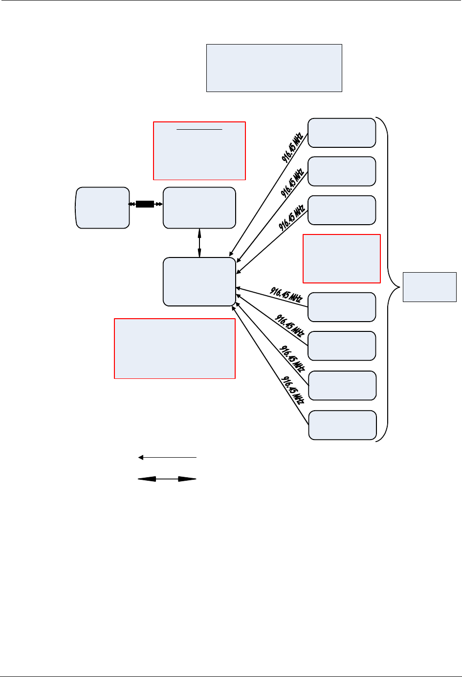
Figure 2.4
RF operation block diagram
The EMTR-3 KV transmits and receives internally stored data using 79 channels
spaced equally across the 902 MHz - 928 MHz band. Channel 1 is at 902.628
MHz, and Channel 79 is at 927.789 MHz. The EMTR-3 KV is primarily a receiver,
but transmits 5-second replies to the Hand Held Transceiver (HHTR) installation
tool during initial installation of the meter. The EMTR-3 KV operates under
Paragraph 15.249 of FCC Regulations and employs frequency shift keying (FSK)
to convey data. No subcarriers are used.
HHTR Data
RF = PIC 18 LF242
902 -928 MHz
UI = PIC 18 LF6720
8 MHz
7.2V NiMH 1600 mAH
Regulated to 5V and 3.3V
EMTR-3 KV Data
Orion Dat
a
916 .45 MHz
Data Rate =
100 kbps
2-level FS
K
+/-
50 Khz
(3 o
f
6)
Orion Transmitter
Orion Transmitter
HHTR
Handheld
Transceiver
PC
Data Transfer
from /
to
HHTR
kV2c™ with
EMTR-3 KV
RF Interface
Orion Transmitter
Orion Transmitter
RF Operation Block Diagram
(TWACS
-Orion Project)
June 22, 2007
Wire Interface to
Water/Gas Meter
Encoder
1-
way RF Link
902- 928 MHz
Bi-
Directional
RF Lin
k
RS- 232
Multi-port EMA provides 1 Electrical port
and 7 RF
p
orts for
g
as/water.
EMA unregulated voltage is 6V to 13V.
EMA regulated voltage is 5V.
Re
g
ulated fro
m
EMA to EMTR-3 KV is 3.3V.
PIC18F 4525
8MHz
F
CC
ID
:
P
N3
Y
7
2
553
-1
Orion Transmitter
Orion Transmitter
Orion Transmitter

28 Universal Metering Transponder for kV2c™ Meter User Guide
Functional Description of the UMT-C-KV
The interface between the EMTR-3-KV and the UMT-C-KV is an Inter-Integrated
Circuit (I2C) physical layer over which the Common Data Layer communications
format operates. The UMT-C-KV performs the gateway function of connecting the
EMTR-3-KV to the TWACS network. TWACS is able to read and write registers
as well as execute Opcodes on the EMTR-3-KV using gateway functionality. The
UMT-C-KV maintains a status indication of the EMTR-3-KV interface as well as
a summary of EMTR-3-KV reported failures. The EMTR-3-KV is optional and
may not be present on all UMT-C-KV units.
R
EGULATORY
D
ATA
This equipment has been tested and found to comply with the limits for a Class
B digital device, pursuant to Part 15 of the FCC Rules. These limits are
designed to provide reasonable protection against harmful interference in a
residential installation. This equipment generates, uses and can radiate radio
frequency energy and, if not installed and used in accordance with the
instructions, may cause harmful interference to radio communications.
However, there is no guarantee that interference will not occur in a particular
installation. If this equipment does cause harmful interference to radio or
television reception, which can be determined by turning the equipment off
and on, the user is encouraged to try to correct the interference by one or
more of the following measures: reorient or relocate the receiving antenna,
increase the separation between the equipment and receiver, connect the
equipment into an output on a circuit different from that to which the receiver
is connected, consult the dealer or an experienced radio/TV technician for
help.
Operation is subject to the following two conditions: (1) This device may not
cause harmful interference, and (2) this device must accept any interference
received, including interference that may cause undesired operation.
Changes not expressly approved by Distribution Control Systems, Inc. could
void the user’s authority to operate the equipment.
On-Request Reads
UMT-C-KV registers can be read directly using this command. Individual or
groups of meters may be read using the TWACS two-way addressing features. See
Two-Way Address.

Universal Metering Transponder for kV2c™ Meter User Guide 29
Chapter 2 • Functional Description
Temperature Monitoring
As an additional safety feature, a solid state temperature sensor within the
UMT-C-KV module measures the internal temperature of the transponder PCB. If,
at any given time, the PCB temperature measured by the thermal sensor is greater
than the value stored in the “Temperature Threshold” register, the module will not
fire, even if the thermal limits controlled by the module firmware have not been
reached.
If any of the thermal limits are reached, (even if the measured temperature
indicates that the transponder's internal temperature is lower than the temperature
threshold) the transponder will not fire.
Two registers store transponder temperature data in degrees Celsius:
• Temperature Threshold register #736
• Internal Temperature register #735
The accuracy of the thermal sensor is within 6 °C in the range from - 40 °C to
+ 125 °C. The resolution of the “Internal Temperature” register is within 1 °C in
the range - 40 to + 125 °C. The Internal Temperature register is updated at
power-up and every 30 seconds thereafter.
When the thermal limit of the transponder is disabled through hardware, the
temperature sensing limits are bypassed and over-temperature safeguards will not
cause the transponder to cease Inbound transmissions.
Historical Data
All quantities captured by the meter data registers (at the time specified by the
Meter Data Daily Shift Time - Register #332) are stored for up to 7 days. Historical
Data also includes a copy of all the Meter Data Registers when the Billing Shift
occurs.
480 Volt Applications
As is widely recognized within the industry, whenever dealing with 480 volt
applications, there are some inherent challenges and risks associated with such
high voltages.
WARNING: The modes of failure in such applications may naturally be more
aggressive than in lower voltage applications. This is an issue with the
industry’s use of 480 volt applications and is by no means limited to GE meters.
Calibration Testing
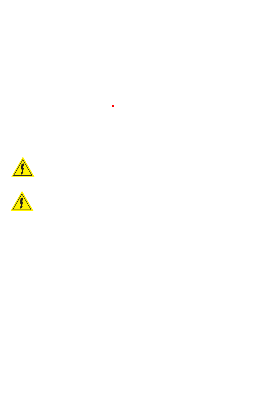
All models support calibration testing of the integral watt-hour meter using
standard meter test equipment. When calibrating an kV2c meter, the optical port is
used to output pulses to the test equipment. The UMT-C-KV transponder uses a
serial link to the optical port for communication with the meter. The transponder
communication must be suspended during meter calibration. This can be done by
sending a time sync command containing a Date 0 Time 0x8700. This indicates an
invalid time and the transponder will not attempt to communicate.

30 Universal Metering Transponder for kV2c™ Meter User Guide
TWACS Installation
N
OTE
If a power down occurs during calibration and the real-time clock has a valid
time, the invalid time sync would need to be sent again.
Options
If a kV2c meter supports KYZ/Form A functionality, the operations of the
UMT-C-KV module shall not, in any way, adversely affect the performance of the
KYZ/Form A inputs or outputs.
TWACS Installation
This section provides an overview of the integration and installation process and
procedures for verifying that the meter is properly reading and communicating
with the network.
Type and Model Numbers
A complete listing of all DCSI Remote Communications Equipment and the
applicable meters can be found on the TWACS portal in the Transponder Type and
Model Matrix. If you do not have access to the portal, contact Customer Care at
Care@twacs.com for assistance.
The following table provides module type, model number, class, voltage, service,
and Energy per Count for each form that is usable with the transponder and meter.
Table 2.8
Model number, class, meter form, voltage, service type, and energy
Type 101
Model
Number Class Form Voltage Service
Energy
Per
Count
1 200 1S 120V-480V
Autorange 2-Wire Single Phase Self-Contained 0.0025
2 200 2S 120V-480V
Autorange 3-Wire Single Phase Self-Contained 0.0025
3 320 2S 120V-480V
Autorange 2-Wire Single Phase Self-Contained 0.00375
4 20 3S 120V-480V
Autorange 2-Wire Single Phase Current
Transformer Rated 0.0025
5 20 4S 120V-480V
Autorange 3-Wire Single Phase Current
Transformer Rated 0.00025
6 20 45S 120V-480V
Autorange 3-Wire Polyphase Current
Transformer Rated 0.00025
7 20 36S 120V-480V
Autorange 4-Wire Polyphase Current
Transformer Rated 0.00025

Universal Metering Transponder for kV2c™ Meter User Guide 31
Chapter 2 • Functional Description
Voltage Transformer (VT) Connected Meter/Transponder
TWACS-enabled kV2c meters that are configured for Voltage Transformer (VT)
connected installations must be treated differently than kV2c meters designed for
direct line voltage applications.
VT-type kV2c meter/transponder hardware combinations are not compatible with
any other kV2c meter/transponder combinations and are, consequently, not
interchangeable. kV2c VT-type meter/transponder combinations are designed to
operate exclusively on either the primary or the secondary winding side of voltage
transformers with nominal secondary voltage of 120V ± 15%.
C
AUTION
Installation of the VT version of a TWACS-enabled kV2c meter on direct line
connected locations without Voltage Transformers could lead to destructive
failure of the device during TWACS communication.
All VT connected meter/transponder combinations are configured at the time of
integration with the necessary parameters for proper TWACS communication.
N
OTE
Installed meters, or meters in the meter shop, can not be retrofitted for VT
applications. New VT meters only must be installed for VT applications.
8 20 8S/9S 120V-480V
Autorange 4-Wire Polyphase Current
Transformer Rated 0.00025
9 200 12S 120V-480V
Autorange 3-Wire Polyphase Self-Contained 0.0025
10 320 12S 120V-480V
Autorange 3-Wire Polyphase Self-Contained 0.00375
11 200 15S/16S 120V-480V
Autorange 4-Wire Polyphase Self-Contained 0.0025
12 320 15S/16S 120V-480V
Autorange 4-Wire Polyphase Self-Contained 0.00375
13 20 3S 120V 2-Wire Single Phase Voltage
Transformer-Rated 0.00025
14 20 4S 120V 3-Wire Single Phase Voltage
Transformer-Rated 0.00025
15 20 45S 120V 3-Wire Polyphase Voltage
Transformer-Rated 0.00025
16 20 36S 120V 4-Wire Polyphase Voltage
Transformer-Rated 0.00025
17 20 8S/9S 120V 4-Wire Polyphase Voltage
Transformer-Rated 0.00025
Type 101
Model
Number Class Form Voltage Service
Energy
Per
Count
32 Universal Metering Transponder for kV2c™ Meter User Guide
TWACS Installation
Verification of Equipment
Avoid damaging the equipment by verifying that the meter, defined by the
nameplate, is compatible with the field socket wiring. Refer to the supported field
installation wiring diagrams in the UMT-C-KV Field Installation Instructions
located on the TWACS portal.
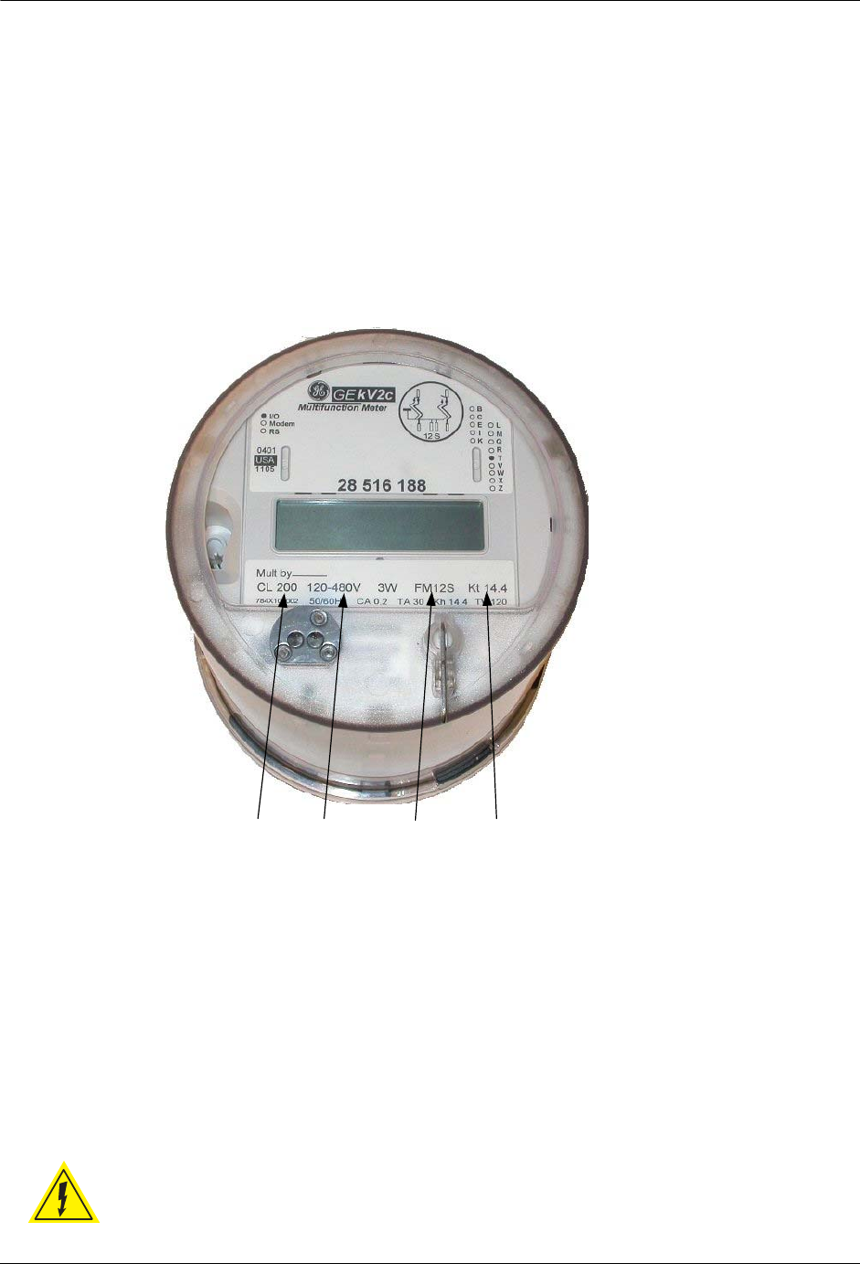
Verify that the meter nameplate has the correct form number, class number, and
voltage. Refer to Figure 2.5 for approximate location of this information on the
meter label.
Figure 2.5
Meter nameplate
N
OTE
Refer to Table 2.8 for information on the form, class, voltage, and Kh.
Installation Procedure
Refer to the appropriate manufacturer meter installation documentation and your
company procedures for the proper safe installation of electric utility meters. For
specific installation instructions, refer to the UMT-C-KV Field Installation
Instructions located on the TWACS portal.
WARNING: When the meter is firmly seated in the base socket, the
conductors in the meter socket are energized.
Class KhFormVoltage

Universal Metering Transponder for kV2c™ Meter User Guide 33
Chapter 2 • Functional Description
To complete the installation process, the meter must be searched into the TWACS
operating software. The following steps provide a general overview of this process.
More detailed information is available in the TNS End User Guide and the TWACS
Network Gateway Operational Process Guide.
1. Obtain, from the installer, the following information for the installed meter.
There are seven pieces of information that identify the location and
communication path and address information of the meter:
•TWACS Serial number (required)
•Substation (required)
•Bus identification
•Feeder identification
•Phase
•Phasor (TNG)
•Transponder Type: 101
2. Enter the necessary information into TWACS operating software by
following the directions in the subsection Searching Meters into TNS, in the
Searching Meters chapter of the TNS Operational Process Guide.
3. The software will start the search process.
Once in the database, the meter is ready for AMR or On-Request reads.
Registers
The Altimus Command Parameters window shows all registers that can be read for
the type of meter selected and the registers that will be read for the rate class
(selected registers, customer class, meter model) and billing type selected
(BILLING or DSHTBILL).
Set up the Altimus Command Parameters table by following the instructions in the
TNS System Administration chapter of the TNS End User Guide.
Thermal Limit
The transponder generates a significant amount of heat when replying to a
command; the longer the command, the greater the amount of heat. Each
transponder type has a message length limit, defined in the transponder
specification and in the Product table. In the Altimus Command Configuration
window, you can see how TNS will break up the reply into segments to avoid
exceeding the thermal limit of the transponder.
See the TNS System Administration chapter of the TNS End User Guide.

34 Universal Metering Transponder for kV2c™ Meter User Guide
TWACS Installation
Changing the Sequence Delay
Normally it is not necessary to change the sequence delay. In the event that it is
necessary to change the sequence delay for one or more rate classes (because of
insufficient time between read commands to permit adequate transponder cooling),
the Altimus Command Configuration window is used.
Change the rate class sequence delay by following the instructions in the TNS
System Administration chapter of the TNS End User Guide.
See Meter Shop Test System on page 39 for more information on testing tools

Universal Metering Transponder for kV2c™ Meter User Guide 35
CHAPTER
3
T
ROUBLESHOOTING
The purpose of this chapter is to provide DCSI customers with procedures that will
assist in determining if a failed meter issue can be resolved in TNS or if a field visit
is required. It is useful for installers and meter shop personnel.
A failed meter or a meter with an invalid response can be the result of several
factors including process, software, or hardware. The following sections provide
steps for, first, trying to identify the problem in TNS (Complete the steps in
Performing Remote Analysis (TNS)), and then conducting a field visit if necessary.
If a field visit is required, proceed to Field Troubleshooting on page 38. Follow
the instructions in Meter Shop Test System on page 39 if the TNS analysis and field
visit steps do not correct the problem.
Use a three-phase approach to troubleshoot the UMT-C-KV.
1. Remote Analysis
2. Field Troubleshooting
3. Meter Shop Test System
For information on loss of power, refer to Loss of Power Handling on page 18.
The UMT-C-KV may spontaneously draw a current surge if TWACS inbound
communication takes place during the test. This may affect the test equipment or
results. This can only occur when the SCE sends an outbound command requesting
a response from the UMT-C-KV.
Performing Remote Analysis (TNS)
Complete the following steps to determine if a field visit is required for an
unresponsive meter. You can end the procedure at any step and correct the problem
when a cause of failure is determined.
1. Check the AMRCOMMFAIL table for TWACS serial numbers that have
excessive AMR Communication Failure counts. This enables you to
identify meters that are consistently failing AMR.
If the meter fail count in the AMRCOMMFAIL table is equal to or greater
than the MaxFailCnt in the TNSDEFAULTS table, the Quality Code (QC)
will be set to RO (Retry Override). When the quality code is RO, the meter
unit map will have changed in the AMRCMDLST2WAY table. The meter
will be attempted the first time, but will not be issued subsequent retries and
must be read manually.

36 Universal Metering Transponder for kV2c™ Meter User Guide
Performing Remote Analysis (TNS)
2. Determine if any error messages have occurred during AMR by checking
the SCE Notification log for any associated hardware issues for the meters
that are not communicating.
N
OTE
The Notification log contains important information about the status of
equipment and is automatically updated by TNS and the SCE. For detailed
information about the Notification log and error messages, see the
Notification Log section of the SCE Logs chapter in the TNS Operational
Process Guide and the Notification Log section in the SCE Maintenance chapter
of the TNS End User Guide.
3. Check for TNS errors that may have occurred because of commands
time-out, or any software related issues in TNS that may have prevented
AMR commands processing.
For more information on time-out issues, see the Encode Command
Parameters section in the TNS System Maintenance chapter of the TNS End
User Guide.
4. Perform an On-Request AMR command to determine if the unit
communicates. (This command communicates to the unit by serial number
to eliminate a two-way addressing issue.)
For more information about On-Request meter reads, refer to the
appropriate sections in the TNS End User Guide and the TNS Operational
Process Guide.
A site visit is not required, and you may stop this procedure if the meter
communicates. If the meter communicates, check two-way addressing.
(For more information on two-way addressing, see the Function-Group
Addressing chapter of the TNS Operational Process Guide and the
Two-Way Addressing section in the TNS Generic Applications chapter of
the TNS End User Guide.)
5. Check for other TWACS meters that are reading on the same distribution
transformer, or a nearby meter to narrow the communication problem area.
6. Check the Customer Information System for a disconnected status that may
not have updated in the TNS database. If the meter was disconnected, no
action in TNS is required, but you may want to change the cycle number.
The TNS Operator must have some process for dealing with a meter that no
longer provides a read. The TNS Operator might consider setting up a
special cycle (e.g. cycle 99) for disconnects and continue reading the
meters. Having the disconnected meters in a special cycle allows the TNS
Operator to isolate meters to scan for usage. If a Customer Service
Representative re-activates the service and the notification fails to reach the
TNS Operator, or if a customer tampers with the meter and reconnects the
service, the TNS Operator can quickly identify a successful read in a group
of meters where reads should normally fail. Using this configuration, the
TNS Operator can quickly investigate the reason for the successful read of a
supposedly disconnected meter.

Universal Metering Transponder for kV2c™ Meter User Guide 37
Chapter 3 • Troubleshooting
7. Check for switching events which may have occurred in the system that
possibly changed the communication path of the meter. (A communication
path may have changed due to a physical move or a temporary switch to a
different substation, phase, or other path component.) If the communication
path has changed, you can use Pathmaps to update the TNS database.
For more information on communication paths, see the Adding Meters
Interactively section in the Searching Meters chapter of the TNS
Operational Process Guide. For more information on Pathmaps, see the
Alternate Pathmaps Search chapter in the TNS End User Guide and the
Building and Searching Alternate Paths chapter in the TNS Operational
Process Guide.
8. Check the Alternate Substation tables for up-to-date information on
Alternate Substations that can feed the primary sub.
For more information on Alternate Substation tables, see the Adding
Alternate Substation Information section in the SCE Maintenance chapter
of the TNS End User Guide. Also see the Alternate Substation Mapping and
Creating and Using Alternate Path Tables sections in the Building and
Searching Alternate Paths chapter of the TNS Operational Process Guide.
Performing Remote Analysis (TWACS NG)
Complete the following steps to determine if a field visit is required for an
unresponsive meter. You can end the procedure at any step and correct the problem
when a cause of failure is determined.
1. If communication fails to the transponder, check the path and search state of
the transponder. You may do this by going to System Monitoring > Edit
Path > Search States.
2. Type in the serial number of the transponder, and click Lookup.
If the transponder is currently in the New, Lost or Tentative path state, the
the TWACS NG will need to search the transponder. The TWACS NG
Operator will need to be sure that it is in a search state of Ready. The search
batch job should automatically pick up the transponder for search when the
next job runs.
3. If the transponder is in a Good/Done state, the TWACS NG Operator may
issue a ping to the transponder. You may do this by going to System
Monitoring > Test Transponder screen.
4. Type in the serial number or Meter/End Device ID, and click Ping.
If the ping is successful, communication to the transponder is successful and
has been verified. If the transponder is still not functioning as expected, a
field visit will most likely be necessary.
5. The TWACS NG Operator may also want to check the notifications to
verify if any have been received for the transponder in question. For more
information regarding notifications, refer to the Notifications section of the
TWACS® Network Gateway Operational Process Guide.
38 Universal Metering Transponder for kV2c™ Meter User Guide
Field Troubleshooting
6. If the previous steps determine that the meter has “Failed”, see on page 40
to return the meter.
N
OTE
For additional information regarding remote troubleshooting, contact
DCSI Customer Care (email care@twacs.com or call 1-800-892-9008) to
speak with a Technical Support Engineer.
Field Troubleshooting
The most likely field troubleshooting scenario is a failure to display. If the
Communication icon is not displaying, ensure that the TWACS-enabled
kV2c meter is receiving the appropriate power according to its specific form and
voltage (refer to Table 2.8 on page 30). You may use a Portable RCE Test Unit
(PRTU) and the PRTU Technical Manual for further testing or return the meter to
the Meter Shop for further diagnostics.
WARNING: Wear all safety equipment according to your utility rules before
opening the meter base: hard hats, safety face shield, fire retardant clothing,
high voltage rated gloves, safety rated shoes.
WARNING: Any work on or near energized meters, meter sockets, or other
metering equipment can present a danger of electrical shock. Such shock
could cause serious injury or death.
Complete the following steps if you determine a field visit is necessary. You can
end the procedure at any step and correct the problem when a cause of failure is
determined.
1. Once on site, verify the correct TWACS serial number is installed at the
site.
2. Determine if the meter is operational by performing a voltage check,
verifying the meter is the correct form and class for the application, and
making sure the service transformer is at least a 3 KVA transformer or
greater.
3. Determine if the meter is disconnected at the service transformer or booted
on the line side of the meter base.
4. Remove the meter and check for loose connections in the meter base or any
other type of defect that may prevent the meter from communicating
through TWACS power line communication.
(( ))

Universal Metering Transponder for kV2c™ Meter User Guide 39
Chapter 3 • Troubleshooting
5. Replace the meter and verify that the Communication icon appears on
the meter display. This icon should display approximately 5-8 seconds after
power up. The icon also displays briefly each minute thereafter, if a valid
time sync has been received.
6. Use the Portable RCE Test Unit (PRTU) to confirm that the TWACS
module is communicating.
N
OTE
If a PRTU is not available, communication with the meter can be verified using
TNS.
7. Instruct the TNS Operator to search the unit into the TNS database while a
technician is on site.
8. If the meter does not communicate, or if a power up indicator is not
validated, replace the meter and repeat steps 6 and 7.
9. If the previous steps determine that the meter has “Failed”, complete the on
page 40 to return the meter.
IMPORTANT
Contact DCSI Customer Care (email care@twacs.com or call 1-800-892-9008)
and arrange to speak with a Technical support Engineer if a new meter does
not successfully communicate from the same site.
Meter Shop Test System
Use the Meter Shop Test System to test TWACS signaling, read select transponder
registers, zero select transponder registers, and perform various other transponder
functions on a TWACS-enabled kV2c meter. For complete details on the Meter
Shop Test System, see the Meter Shop Test System Help (accessed by clicking the
Help button on the Meter Shop Test Tool main menu) or contact your Program
Manager or DCSI Customer Care at care@twacs.com or 1-800-892-9008.
Because of the various test equipment available for use with DCSI products and the
configuration requirements/options, the Meter Shop Test System Set-Up Guide,
will guide you through initial equipment selection and setup for meter/module
testing.
This UMT-C-KV user guide contains all the module-specific information
necessary to test the UMT-C-KV installed in the kV2c meter. UMT-C-KV module,
TWACS serial number, and meter-specific information is available on the meter
label. Refer to Figure 2.5 on page 32. Additional information, such as module
Type and Model, can be found in Table 2.8 on page 30 of this user guide.
If you are unable to resolve a problem with the UMT-C-KV, return the meter to
your integrator or DCSI. See Product Returns on page 3.
N
OTE
To use the Meter Shop Test System optical port communication option with a
TWACS-enabled kV2c meter, you must have an Optical Port Cable Assembly
(see Figure 3.1).
(( ))
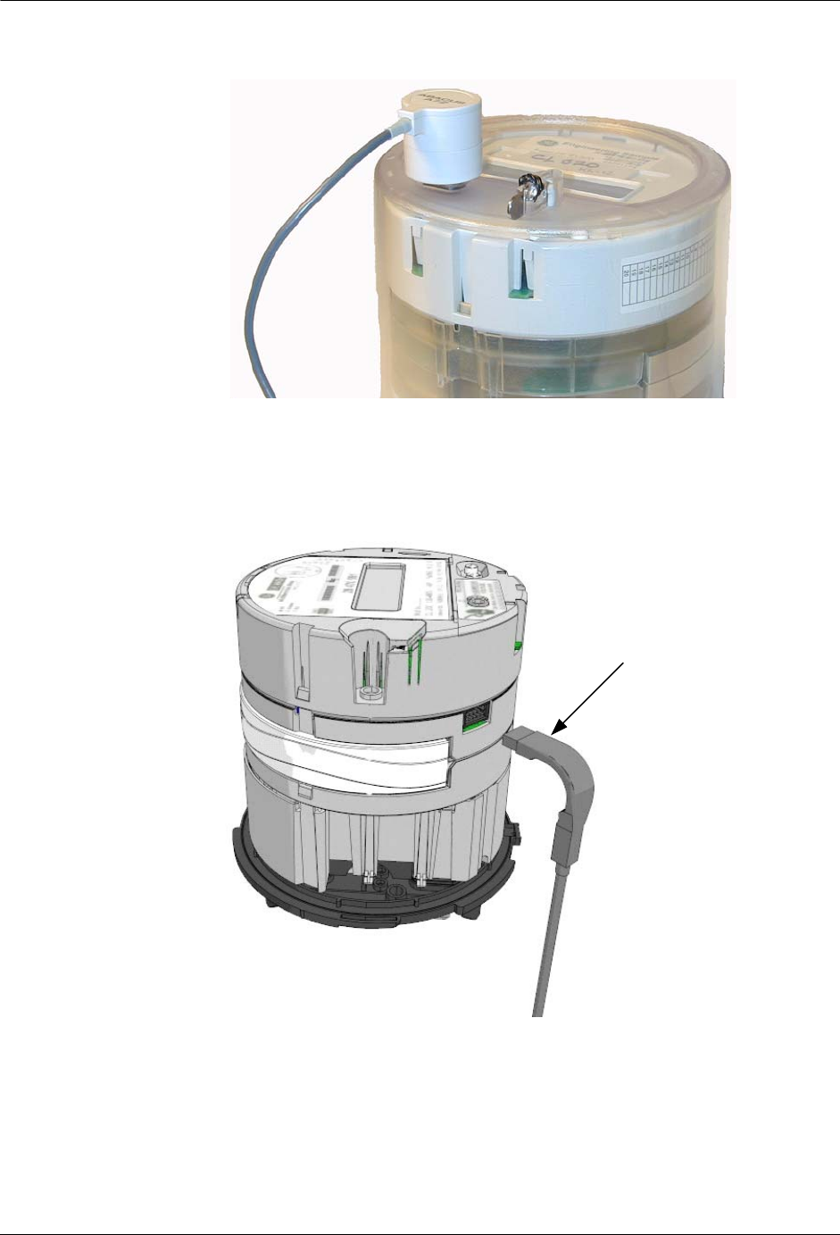
40 Universal Metering Transponder for kV2c™ Meter User Guide
Meter Shop Test System
Figure 3.1
Optical port connection for kV2c meter
N
OTE
To use the Meter Shop Test System serial communication option with a
TWACS-enabled kV2c meter, you must have the correct SIA Cable Assembly (see
Figure 3.2).
Figure 3.2
SIA cable assembly for kV2c meter
SIA Cable Assembly
Y71119-1

Universal Metering Transponder for kV2c™ Meter User Guide 41
CHAPTER
4
S
PECIFICATIONS
This chapter contains electrical, environmental, and physical specifications for the
UMT-C-KV transponder.
Electrical Specifications
Compliance Specifications
N
OTE
ANSI C12.1-2001 is the referring standard for tests listed in tables 3.2, 3.3, and
3.4.
Table 4.1
Electrical ratings
Parameter Rating
Line voltage 120-480 VAC +/- 15%
Line frequency 60 Hz +/- 3.0 Hz
Quiescent power 1.35 Watts not including TWACS or RF
activity
Maximum input surge 25 amps RMS
Internal fusing Yes on AC connection for TWACS
Grounding None
Electronics connection DC energy is provided by the kV2c Meter
Electronics isolation Electronics are not required to be
electrically isolated from the power line.
Table 4.2
Compliance specifications
Test Title Applicable Specification
EMI/RFI Emission
conducted/radiated ANSI C12.1-2001 Test No. 27- “Radio
Frequency Conducted and Radiated Emissions”
per CFR 47 Part 15, Class A and B. (See also
ANSI C63.4)
EMI/RFI Susceptibility ANSI C12.1-2001 Test No. 26- “Effect of Radio
Frequency Interference”
Canada: LMB-EG-07 & PS-E-09-E
AC line surge ANSI C12.1-2001/IEEE C62.41-1991 Test
No. 17- “Effect of High Voltage Line Surges”
Canada: 61000-4-4:2004
Electrical fast transient ANSI C12.1-2001 Test No. 25- “Electrical Fast
Transient/Burst” (Testing at 100 KHz is
required) IEC 61000-4-4: 2004

42 Universal Metering Transponder for kV2c™ Meter User Guide
Environmental Specifications
Environmental Specifications
Surge withstand
capability FT and OSC ANSI/IEEE C.37.90.1 - 2002
High voltage isolation on
meter chassis ANSI C12.1-2001 Test No. 15- “Insulation”.
Canada: LMB-EG-07 & PS-E-09-E
Voltage interruption test ANSI C12.1-2001 Test No. 16- “Voltage
Interruption”.
Electrostatic Discharge ANSI C12.1-2001
Test No. 28 “Effect of electrostatic discharge
(ESD)”.
Variation of Voltage ANSI C12.1-2001
Test No. 5 & 5a “Effect of variation of voltage
on the metering device”.
Variation of Frequency ANSI C12.1-2001
Test No. 6 “Effect of variation of frequency”.
Dielectric Voltage ANSI C12.1 Test for: Withstand, Abnormal
Voltage Operation, and Faults.
Circuit spacing Circuit spacing complies with sound engineering
principles for 480-volt class equipment.
ITIC (CBEMA) IEC 61000-4-11.
Effect of Variation of
Voltage Test No. 5 & 5a, performed at 80% to 115% of
rated voltage, with 5% or smaller steps.
Effect of Variation of
Frequency Test No. 6.
Effect of External
Magnetic Field Test No. 18.
Occupied Bandwidth 200 kHz.
RF Output Power 0 dBm or less. The EMTR-3 KV meets FCC
section 15.249 for field strength of emissions.
Carrier Frequency
Stability Carrier frequency is crystal controlled. Accuracy
is +/- 50 ppm, or about +/- 46 kHz.
Table 4.2
Compliance specifications
Test Title Applicable Specification
Table 4.3
Environmental specifications
Thermal
Effect of operating temperature Per ANSI C12.1-2001 Test No. 30
Humidity
Effect of relative humidity, both
operational and storage Per ANSI C12.1-2001 Test No. 31

Universal Metering Transponder for kV2c™ Meter User Guide 43
Chapter 4 • Specifications
Physical Specifications
Table 4.4
Physical specifications
Parameter Specification
Size, weight, form factor
Integrated dimensions 6.94 in. dia. x 8.2 in. lng. - Refer to General
Electric specifications for kV2c meter
Integrated weight kV2c meter w/ plastic cover 2 lbs.
Integrated kV2c w/plastic cover 3.5 lbs.
Meter forms See Table 2.8, “Model number, class, meter
form, voltage, service type, and energy”.
Installation instructions Installation instructions can be downloaded from
the DCSI Web portal (https://portal.twacs.com).
Meter socket ANSI C12.7-1987
Compliance Testing Specifications
Mechanical tests
• Mechanical Shock
• Mechanical Vibration
• Transportation Drop Test
• Transportation Vibration
Per relevant sections of ANSI C12.1 - 2001
described below:
• Test #32, per IEC 60068 part 2-27
• Test #34, per IEC 60068 part 2-6
• Test #33, per ISTA Test Procedure 1A
• Test #35, per ISTA Test Procedure 1A
Labeling Requirements, Faceplate and
Serial Number
All models
Labeling per ANSI C12.10-1987 and/or
customer specifications for:
•TWACS logo
• Model number
• Model number barcode
• TWACS serial number
• TWACS serial number barcode
The TWACS Serial Number is embedded
in the utility's meter number. It must be a
distinguishable field of the meter number,
or may be duplicated elsewhere on the
faceplate. The serialized electronics and
faceplate must be kept together.
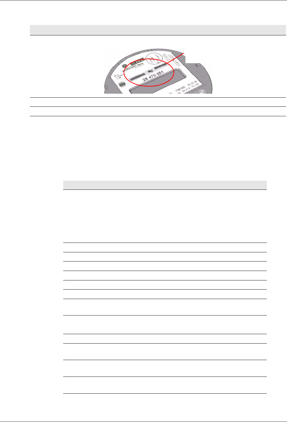
44 Universal Metering Transponder for kV2c™ Meter User Guide
Additional Regulatory Data
Additional Regulatory Data
The following is a tabulation of regulatory data found elsewhere in this manual and
is required by the regulatory agencies of some countries.
Physical Tamper Protection
Meter seal Supported
Table 4.4
Physical specifications
Parameter Specification
TWACS
Serial
Number
Parameter Specification
Disclaimer noting that
operation of the device is
subject to conditions and that
the device may not cause
harmful interference and device
must accept any interference
received.
Regulatory Data note on page 28.
Principles of device operation All of Chapter 2.
Block diagram Page 27.
Operating frequency 902-928 MHz, page 27, paragraph 1.
Channeling Page 27, paragraph 1.
Mode of transmission Page 27, paragraph 1.
Internal/External data source Page 27, paragraph 1.
Type(s) of modulation Frequency Shift Keying, page 27,
paragraph 1.
Is a subcarrier used to modulate
carrier? No. Page 27, paragraph 1.
Type of information transmitted Digital data, page 27, paragraph 1.
Occupied bandwidth 200 kHz, page 42, third-to-last item in
table.
RF output power FCC 15.249 compliant, page 42,
second-to-last item in table.
Carrier frequency stability +/- 50 ppm or +/- 46 kHz, page 42, last
item in table.

Universal Metering Transponder for kV2c™ Meter User Guide 45
AC Alternating Current
ADLC Asynchronous Data Link Communication
AMR Automatic Meter Reading
ANSI American National Standards Institution
ASCII American National Standard Code for Information Exchange
CIS Customer Information System
DC Direct Current
DCSI Distribution Control Systems, Inc.
IEEE Institute of Electrical and Electronics Engineers
kWh Kilowatt Hours
LCD Liquid Crystal Display
MC Master Controller
MS Master Station
MSTT Meter Shop Test Tool
NS Register Not Supported
PRTU Portable RCE Test Unit
RCE Remote Communications Equipment
RMA Return Material Notice
RTC Real Time Clock
SCE Substation Communications Equipment
TCT Test Communication Tool
TNS TWACS Net Server
TWACS Two-Way Automatic Communication System
TWACS® NG TWACS® Network Gateway
UMT Universal Metering Transponder
Acronyms

46 Universal Metering Transponder for kV2c™ Meter User Guide
Acronyms

Universal Metering Transponder for kV2c™ Meter User Guide 47
address
An assigned unique, fixed number to a memory location in order to retrieve or store data.
Automatic Meter Reading (AMR)
Electronic accumulation and transport of meter data. The process of reading a meter from a
remote location at scheduled times or on demand.
bins
A register to store the read data.
bus
An electrical common connection through which power is distributed.
bus identification
Identifies the substation bus to which DCSI equipment is connected.
Central Control Equipment (CCE)
The top level of the TWACS hierarchy, also referred to as the master station. The CCE
typically resides at the utility home office, providing system control and data storage for
TWACS.
Customer Information System (CIS)
A computer database that utilities use to keep track of their customer information (name,
address, phone, meter serial number). Often includes bill printing functionality.
energized meter
A meter that is electrically charged
feeder identification
Identifies which feeders are connected to which bus(es).
hourly interval
A statistical count of hourly usage.
integration
The installation of the transponder into the meter.
Master Controller (MC) or Master Station (MS)
The equipment at the utility's home office that provides system control, data storage, and user
interface functions for the system.
Glossary

48 Universal Metering Transponder for kV2c™ Meter User Guide
Glossary
Meter Shop Test Tool (MSTT)
A software product developed by DCSI that performs troubleshooting and testing of meters.
non-volatile data
Data that is preserved even when the electrical power is off.
phase
The current supply conductors, other than the neutral conductor of a polyphase circuit, that
usually carry the designation phase A, phase B, or phase C.
Portable RCE Test Unit (PRTU)
Portable unit for testing a TWACS-enabled device at a customer site. The PRTU, used in
conjunction with a laptop running Meter Shop Test Tool software, generates and decodes
TWACS signals for communication with a TWACS-enabled device.
pulse accumulation
A device that accepts and stores pulses
registers
Devices, such as transponders, located at a consumer's premises that collect and transmit
register data through TWACS.
Remote Communications Equipment (RCE)
The base of the TWACS hierarchy. RCEs consist of the DCSI family of transponder products.
RCEs are located at customer sites and interface TWACS communication with various end
devices such as meters, water heaters, and air conditioning units to enable automatic meter
reading (AMR), load management, or other functions.
rollover
An event, when the meter reading changes from its maximum value to zero.
Substation Communications Equipment (SCE)
The middle tier of the TWACS hierarchy, consisting of all TWACS substation equipment
(CRU, OMU, IPU, and MTU). The SCE transmits and receives data between the Master
Station and RCE.
synchronization
A means of ensuring that both transmitting and receiving units are operating together.
tampering
To alter improperly

Universal Metering Transponder for kV2c™ Meter User Guide 49
Glossary
Total Consumption (TC)
The total electrical usage (in kWh) for the specified type of meter read.
transponders
Two-way field devices that can receive and send messages to and from the substation.
TWACS Next Generation (TNG) or TWACS Net Server (TNS)
Chief component of the entire Two-Way Automatic Communication System. Manages all
collected metering and interval data as well as the connection between the utility and the
consumer’s premises.
Two-Way Automatic Communication System (TWACS)
A patented technology that allows the utility to send and retrieve information to and from
meters and other devices using the utility’s power lines as a communication network.
Universal Metering Transponder (UMT)
An electronic assembly integrated into an electric meter to add TWACS communications
capability to the meter.
volatile data
Data that is lost when the electrical power is off.

50 Universal Metering Transponder for kV2c™ Meter User Guide
Glossary

Universal Metering Transponder for kV2c™ Meter User Guide 51
Numerics
480 volt applications 29
A
AC input voltage 25
addressing modes 15
TWACS-10 15
TWACS-20 15
Altimus Command Configuration 33
AMR 33
ANSI 12
B
bus identification 33
C
calibration testing 29
care@twacs.com 3
compliance specifications 41
consumption 17
Customer Care 3
D
daily shift 12
data retrieval 13
daylight saving time 10
demand reset 23
E
electrical specifications 41
EMTR-3 26
energy 17
energy and demand measurement 22
environmental specifications 42
F
faceplate 43
feeder identification 33
functional description 9, 11
H
historical data 29
hourly reads 12
I
inbound generation circuitry 12
interval data 17
L
labeling requirements 43
M
maintenance 40
Master Station 6
Meter 39
meter data registers 26
meter map registers 26
meter shop testing 39
meter socket 12
microprocessor 12
N
nonvolatile memory 12
O
On Request Read 33
outage duration 19
outage monitoring 28
outbound detection circuitry 12
P
phase 33
physical specifications 43
polyphase 20
polyphase commercial meter 10
portal 3
power loss detection 12
R
Remote Communications Equipment 6
response modes
TWACS-10 16
TWACS-20 16
return procedures 40
S
sequence delay 34
serial communication port 13
serial date 9
serial number 33
serial number address 13
serial port 12
serial time 9
serial time units 9
Set Date/Time command 9
specifications
compliance 41
electrical 41
environmental 42
physical 43
STU
Index

52 Universal Metering Transponder for kV2c™ Meter User Guide
Index
See Serial Time Unit 9
substation 33
Substation Communications Equipment 6
support 3
T
Technical Support 3
temperature monitoring 29
theory of operation 9, 10
time synchronization 17, 25
time-of-use 18
TNS 6, 33
primary functions 6
TNS Operational Process Guide 4
transformer 25
troubleshooting
field 38
TWACS
three levels of components 6
TWACS-10 Communication Protocol 14
TWACS-20 Communication Protocol 14
two-way address 13
Two-Way Automatic Communication System
inbound generation circuitry 12
outbound detection circuitry 12
V
voltage transformer 25
W
Write RCE Register command 14