Aclara Technologies 2013001 LLB2013001 TRANSCEIVER MODULE User Manual
Aclara Technologies LLC LLB2013001 TRANSCEIVER MODULE Users Manual
Contents
- 1. Users Manual
- 2. Field Manual
Users Manual

www.Aclara.com
STAR
ZoneScan
Technical Manual
Y20284-TUM
Rev. C
®

STAR ZoneScan Technical Manual (Y20284-TUM Rev C)
Proprietary Notice
The information contained in this document is private to Aclara Technologies LLC an Ohio
liability company (Aclara). This information may not be published, reproduced, or otherwise
disseminated without the express written authorization of Aclara.
Any software or firmware described in this document is furnished under license and may be used
or copied only in accordance with the terms of such license.
Disclaimer
The information in this document is subject to change without notice and should not be construed
as a commitment by Aclara. Aclara assumes no responsibility for any errors that may appear in
this document.
No responsibility is assumed for the use or reliability of any software on equipment that is not
supplied by Aclara.
TWACS and STAR are registered trademarks of Aclara Technologies LLC. All other registered
trademarks are property of their respective owners.
A product of
Aclara Technologies LLC
Confidential and Proprietary
Copyright 2010-2013. All Rights Reserved.

STAR ZoneScan Technical Manual iii
STAR ZoneScan Installation
Purpose & Scope . . . . . . . . . . . . . . . . . . . . . . . . . . . . . . . . . . . 1
What You’ll Learn . . . . . . . . . . . . . . . . . . . . . . . . . . . . . . . . . . 1
Acoustic Leak Detection Overview . . . . . . . . . . . . . . . . . . . . . . . . . . . 2
Sources of Noise . . . . . . . . . . . . . . . . . . . . . . . . . . . . . . . . . . 2
STAR ZoneScan Leak Identification Process . . . . . . . . . . . . . . . . . . . . . . . 3
STAR ZoneScan Leak Detection System Components . . . . . . . . . . . . . . . . . . . 4
STAR ZoneScan MTU Installation Procedure . . . . . . . . . . . . . . . . . . . . . . . 5
Accessories. . . . . . . . . . . . . . . . . . . . . . . . . . . . . . . . . . . . . 5
Recommended Tools. . . . . . . . . . . . . . . . . . . . . . . . . . . . . . . . . 5
Installation/Activation Procedure. . . . . . . . . . . . . . . . . . . . . . . . . . . 6
Deactivation/Redeployment Procedure . . . . . . . . . . . . . . . . . . . . . . . 17
STAR Sync Application Configuration . . . . . . . . . . . . . . . . . . . . . . . . . 21
Uploading Activity Logs to the NCC . . . . . . . . . . . . . . . . . . . . . . . . . 23
STAR ZoneScan Operation
Purpose & Scope . . . . . . . . . . . . . . . . . . . . . . . . . . . . . . . . . . 27
What You’ll Learn . . . . . . . . . . . . . . . . . . . . . . . . . . . . . . . . . 27
STAR ZoneScan System Operation . . . . . . . . . . . . . . . . . . . . . . . . . . 28
Recording Data . . . . . . . . . . . . . . . . . . . . . . . . . . . . . . . . . . 29
Viewing STAR ZoneScan Data . . . . . . . . . . . . . . . . . . . . . . . . . . . . 29
Connecting to Gutermann ZoneScan net website. . . . . . . . . . . . . . . . . . . 33
Table of Contents

iv STAR ZoneScan Technical Manual
Table of Contents
STAR ZoneScan Technical Manual 1
CHAPTER
1
STAR Z
ONE
S
CAN
I
NSTALLATION
Purpose & Scope
This instruction outlines general practices and procedures for the installation of
STAR ZoneScan leak detection MTUs.
What You’ll Learn
Topics covered in this chapter include:
• fundamentals of acoustic leak detection
• system components required for leak detection
• installation/activation of STAR ZoneScan MTUs
• deactivation/redeployment of STAR ZoneScan MTUs
• upload procedure for Activity Logs

2STAR ZoneScan Technical Manual
Acoustic Leak Detection Overview
Acoustic Leak Detection Overview
Management of water leakage consists of four key activities which include:
• measuring water loss
• locating leaks
• monitoring leakage
• repairing leaks
In order to understand leak noise, it is important to know the various sources of
constant noise. Acoustic leak detection equipment collects and evaluates this noise
to identify the probability of a leak.
Sources of Noise
The sources of constant noise in the water pipes include:
• leakage
• partial obstruction of pipe bore
• consumption (flow & meters)
• pressure reducing valves (PRVs)
• partially closed valves (throttled or passing)
• close proximity of main to sewer pipe
• changes in pipe diameter
• water pumping - swimming pool pumps
• electrical hum
• pipe lining
• air conditioning
STAR ZoneScan Installation
STAR ZoneScan Technical Manual 3
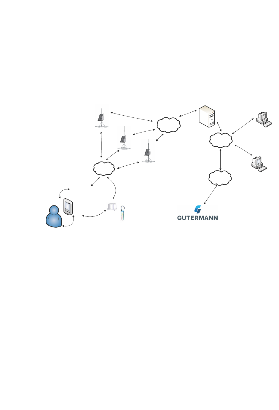
STAR ZoneScan Leak Identification Process
Data loggers are devices that continuously monitor and analyze leak noise in a
water distribution system. They are attached to valve stems on water mains
throughout the pipeline network. Each data logger is cable-connected to an Aclara
STAR ZoneScan MTU that mounts on the underside of a non-metallic valve
cover.Acoustic data collected by the logger is transmitted by the STAR ZoneScan
MTU to Data Collector Units (DCUs) and on to the Network Control Computer
(NCC). In addition to displaying system operational data, the NCC makes the
acoustical data available to the Gutermann application software.
'&8,,
078
+DQGKHOG
1&&
2SHUDWLRQV
±
0+]5)
,;577
%LOOLQJ
67$5=RQH6FDQ
078
/$1
=RQH6FDQ$SSOLFDWLRQ
6RIWZDUH
:::

4STAR ZoneScan Technical Manual
STAR ZoneScan Leak Detection System Components
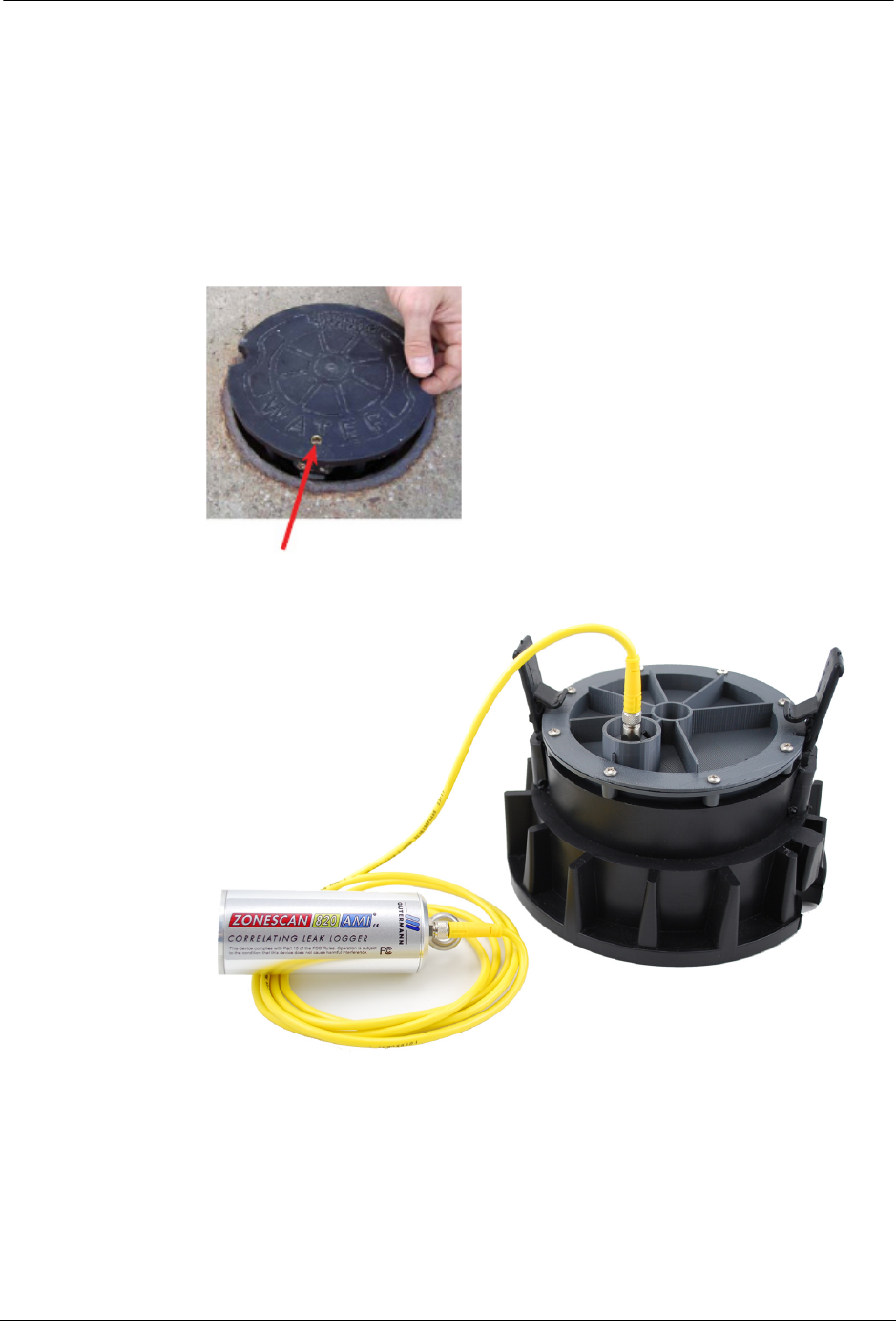
STAR ZoneScan Leak Detection System Components
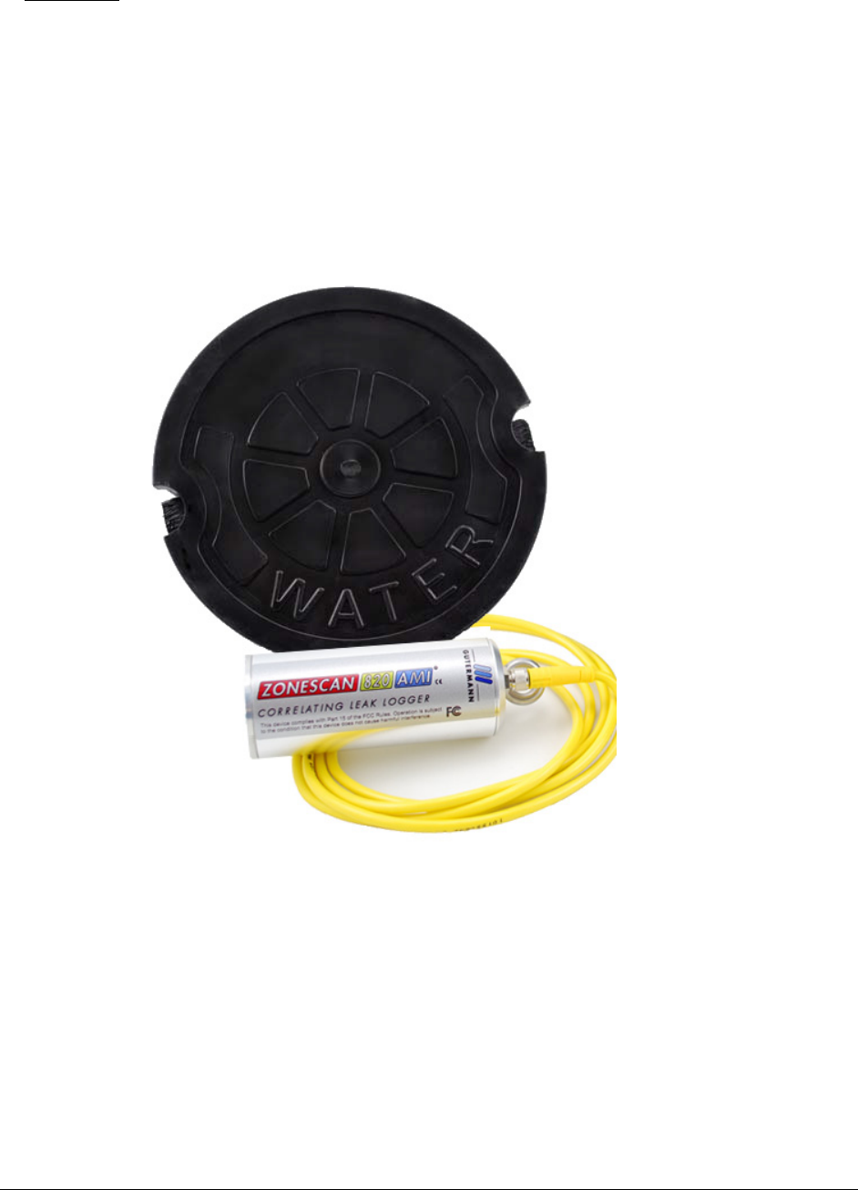
Each STAR ZoneScan unit (Product #4381-506-Z) includes the following
components:
• Gutermann Model 820 data logger with watertight connector cable
• STAR ZoneScan MTU with connector cable
• Circular 7-1/4" diameter non-metallic valve cover
• Web-based application software
The following hardware and software is required to support STAR ZoneScan leak
detection:
• NCC Software Version 7.3.4.3 or higher (7.4.1 or higher recommended) with
ZoneScan software option
• Windows-based field programmer with probe
• DCUIIs with J-boards and STAR ZoneScan firmware
• STAR Programmer Software Version 2.0.6.19 or higher (2.1.1 or higher
recommended)
For new systems, the Network Control Computer (NCC) and Data Collector Units
(DCUs) noted above must be installed and operational prior to installing
STAR ZoneScan MTUs. For existing systems, NCC and DCU upgrades must be
completed and operational prior to installing STAR ZoneScan MTUs. Please
contact your Aclara representative to schedule the necessary DCU and/or NCC
upgrades.

STAR ZoneScan Installation
STAR ZoneScan Technical Manual 5
STAR ZoneScan MTU Installation Procedure
Accessories
We recommend the following supplies. Quantities depend on the number of MTUs
to be installed and the conditions that will be encountered at each location.
• 6-foot extension cable (Aclara PN 070-2009-002F)
• 1/4” rope (nylon or polyproplene)
Recommended Tools
• Safety goggles
• #1 Phillips screwdriver
• 3/16” Allen wrench
• Pry bar
• Wire brush
• Flashlight
• Field Programmer with cable, programming coil and STAR Programming
Software
• Portable GPS device (if Field Programmer does not have GPS capability)
6STAR ZoneScan Technical Manual
STAR ZoneScan MTU Installation Procedure
Installation/Activation Procedure
Perform the following steps to properly install and activate a STAR ZoneScan
MTU.
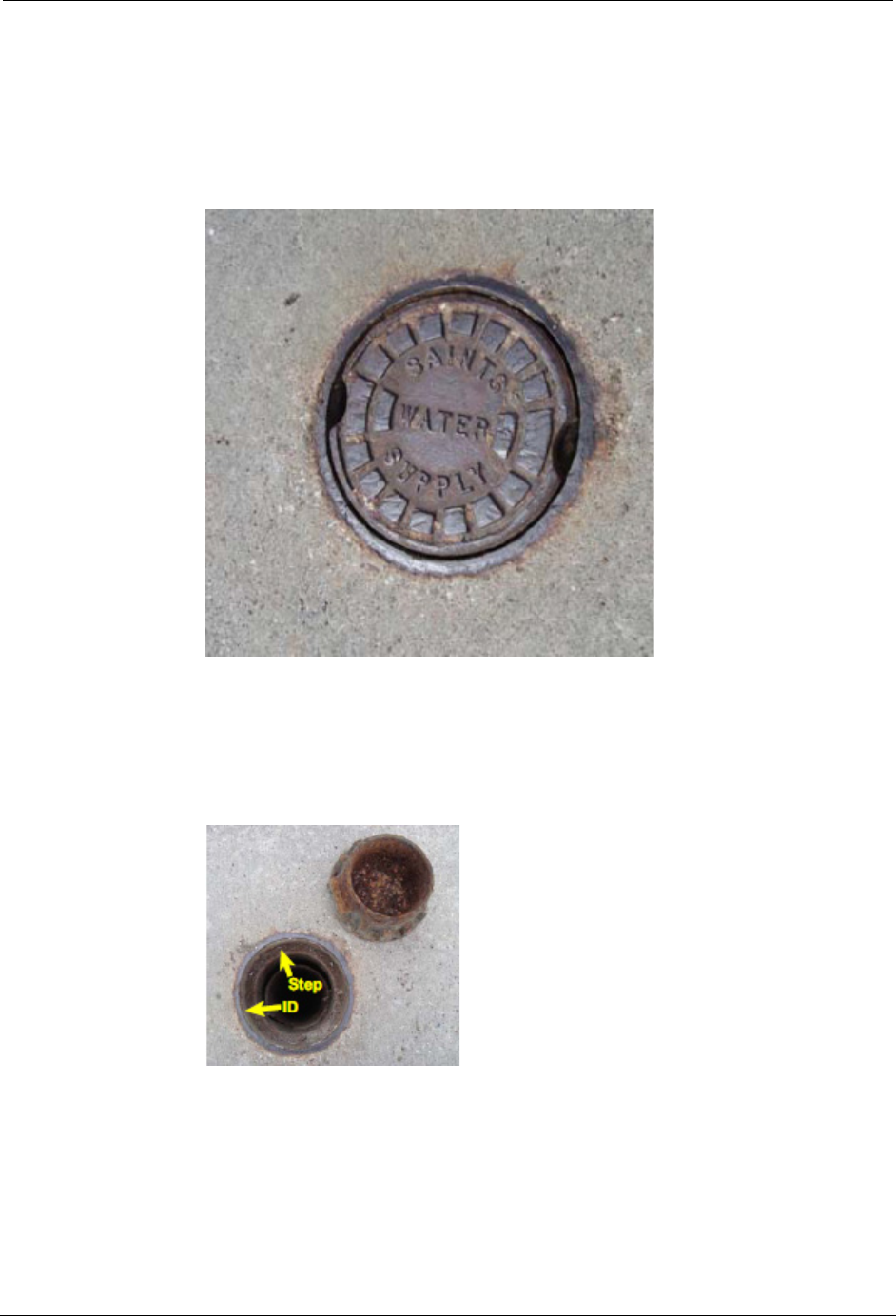
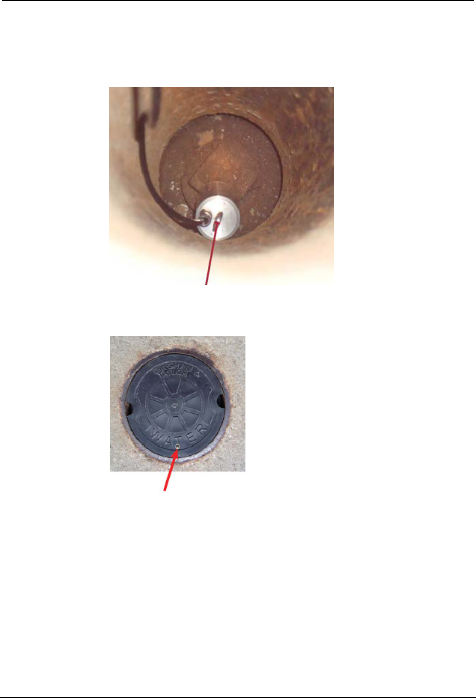
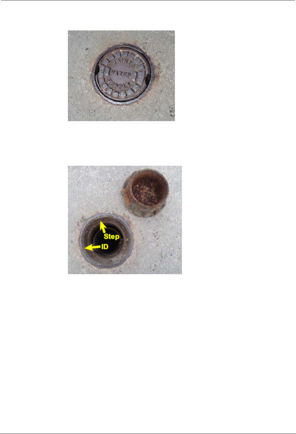
1. Locate valve cover.
2. Remove existing valve cover and set it aside. Clean the entire ID and step
surface areas with a steel wire brush to remove any obstructions that would
prevent the top of the new cover from laying even with the top surface of
the opening.
STAR ZoneScan Installation
STAR ZoneScan Technical Manual 7
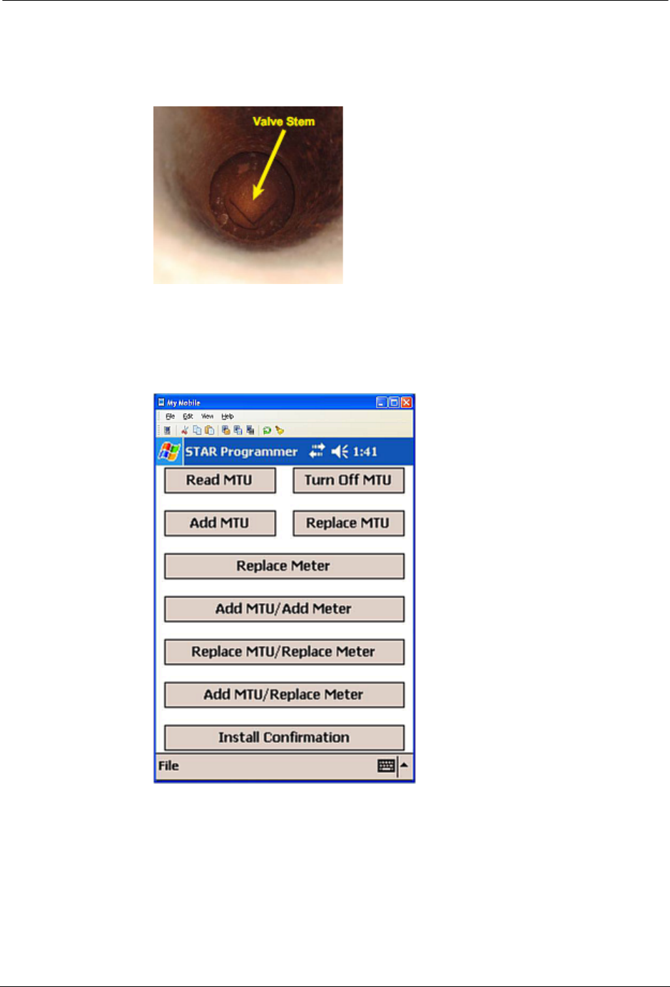
3. Use flashlight to inspect valve stem at bottom of valve chamber. Brush off
any debris. Ensure valve stem is clean to provide a good connection with
the data logger.
4. Verify that the date and time on the Field Programmer are correct.
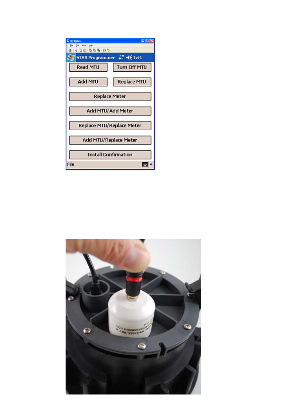
5. Navigate to the STAR Programmer software on the Field Programmer and
log on with your assigned username and password. This menu screen will
appear after successfully logging on.
8STAR ZoneScan Technical Manual
STAR ZoneScan MTU Installation Procedure
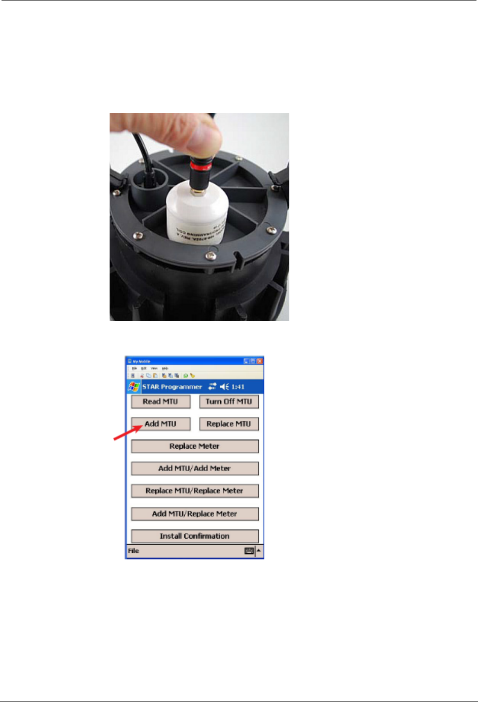
6. Place programming coil in the largest radial slot on MTU casing as shown
below.
N
OTE
There is only one radial slot large enough to seat the entire programming coil.
7. Tap Add MTU.
STAR ZoneScan Installation
STAR ZoneScan Technical Manual 9
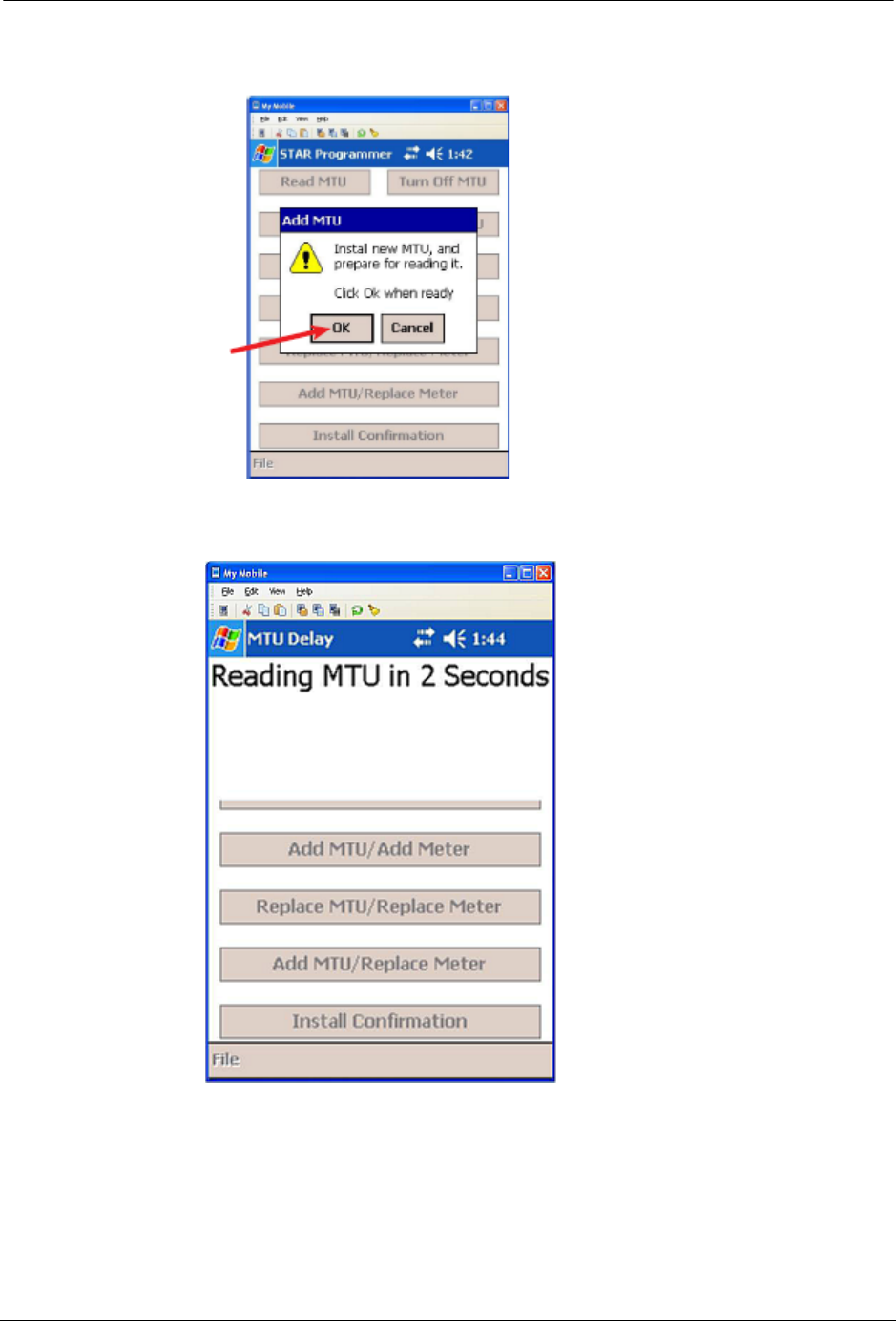
8. Tap OK in the Add MTU window.
9. Wait while the software reads the MTU within three (3) seconds.
10 STAR ZoneScan Technical Manual
STAR ZoneScan MTU Installation Procedure
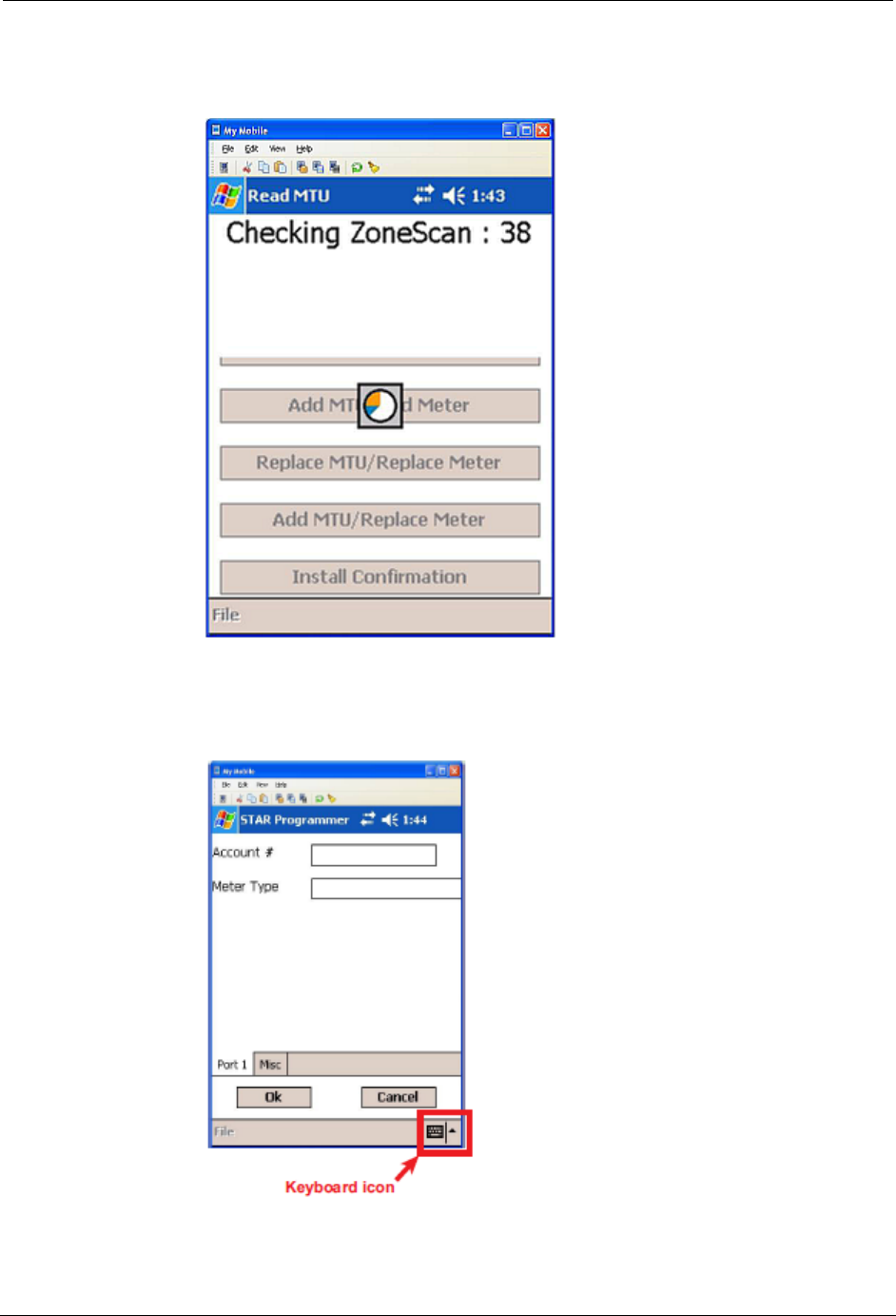
10. Wait while the software checks the STAR ZoneScan unit. This could take
up to 40 seconds.
11. When the software successfully reads the STAR ZoneScan MTU, the
following screen will appear.
STAR ZoneScan Installation
STAR ZoneScan Technical Manual 11
N
OTE
The icon for the on-screen keyboard appears only on user input screens. Tap
the icon in the lower right corner of the touch screen to open the on-screen
keyboard.
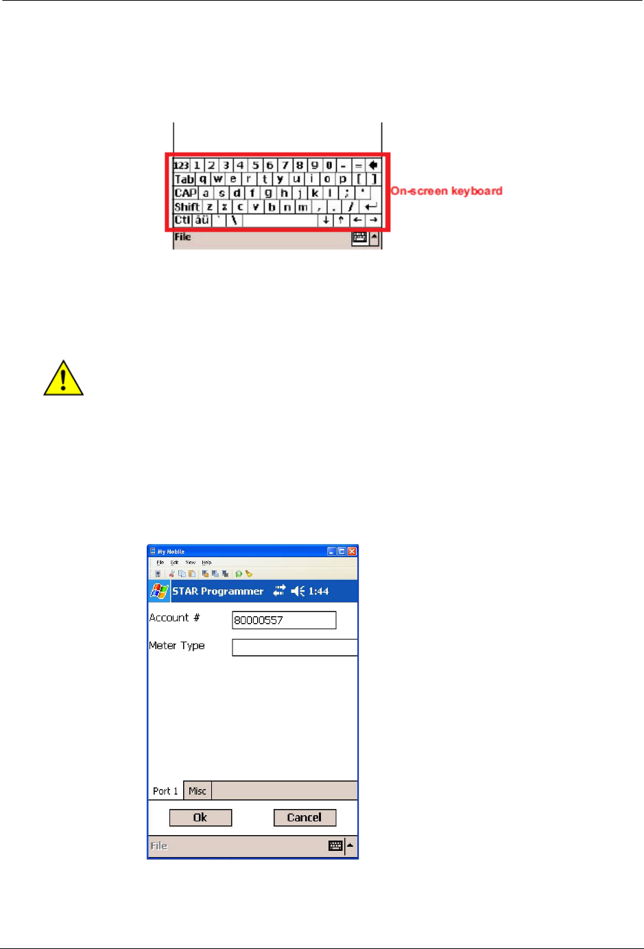
When working with an on-screen keyboard, select a specific key by tapping it with
a stylus. Tap keyboard icon again to remove on-screen keyboard from the display.
C
AUTION
Do not use anything other than an approved stylus because you may damage
the touch screen with items such as a pen, screwdriver, etc.
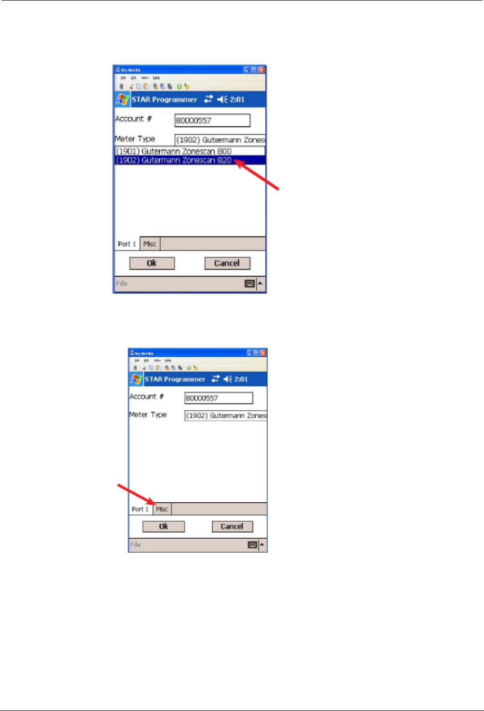
12. Enter an account number with up to 12 alpha, numeric or alphanumeric
characters in the Account # field.
N
OTE
A unique account number is not necessary for each STAR ZoneScan MTU.
Create an account number that will identify all STAR ZoneScan MTUs in the
system.
12 STAR ZoneScan Technical Manual
STAR ZoneScan MTU Installation Procedure
13. Select (1902) Gutermann ZoneScan 820 from the Meter Type pull-down
menu.
14. Tap the Misc tab.
STAR ZoneScan Installation
STAR ZoneScan Technical Manual 13
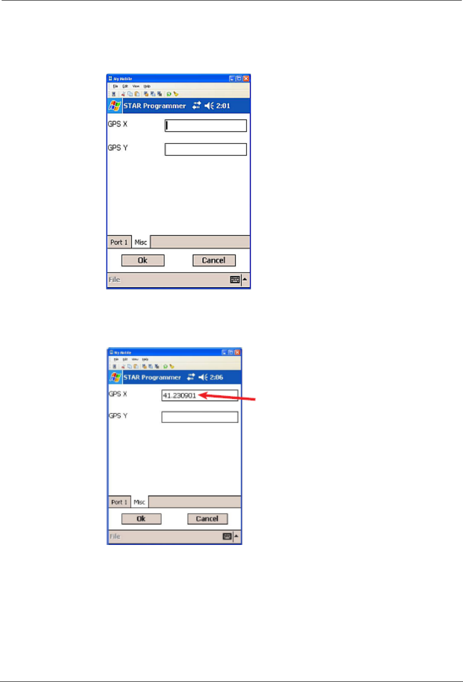
15. The Misc tab is displayed with the GPS coordinate fields. Position Field
Programmer (if GPS capable) or portable GPS device directly over valve
pipe.
16. Enter the GPS X (latitude) coordinate to six (6) decimal places into the
Field Programmer.
N
OTE
If the specific field programmer has GPS capability, the two GPS X and Y fields
may fill automatically. In this case, no manual entry of coordinates is needed.
14 STAR ZoneScan Technical Manual
STAR ZoneScan MTU Installation Procedure
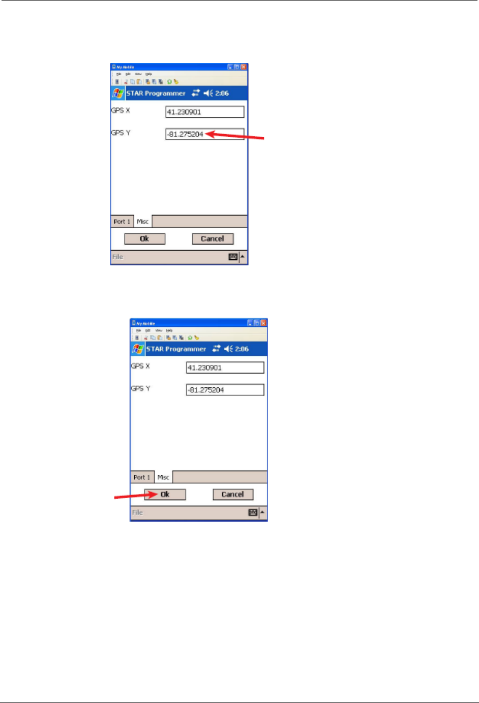
17. Enter the GPS Y (longitude) coordinate to six (6) decimal places into the
Field Programmer.
18. Tap Ok to complete STAR ZoneScan programming.
STAR ZoneScan Installation
STAR ZoneScan Technical Manual 15
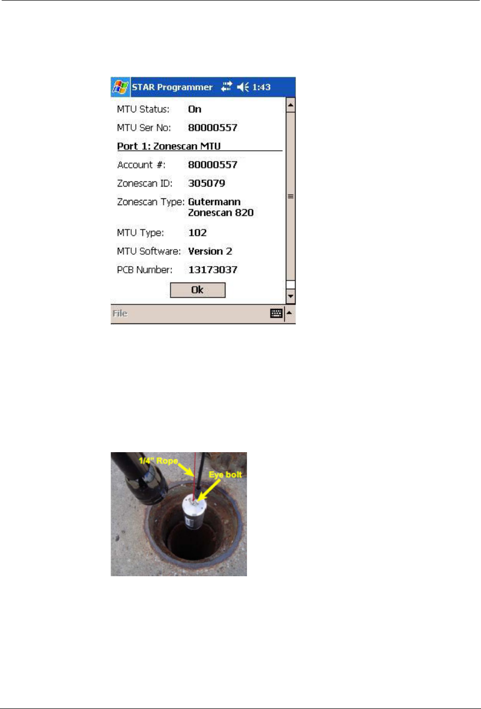
19. When the STAR ZoneScan programming is completed, the following
screen will appear with information displayed related to the specific
installation.
20. Verify that the account number is correct and the MTU Status is On. If the
information is correct, complete programming by clicking the OK button.
The system will then return to the main STAR menu.
21. Attach a 1/4" rope (nylon or polypropylene) to the eye bolt on the ZoneScan
logger. Slowly lower the data logger down the valve chamber by only the
1/4" rope and not the cable.
16 STAR ZoneScan Technical Manual
STAR ZoneScan MTU Installation Procedure
22. Make sure magnet on bottom of data logger comes into contact with valve
stem and ensure they are securely coupled. Securely tie the other end of the
rope to the pit lid by providing additional rope length as slack when
removing valve cover.
23. Place a non-metallic valve cover onto chamber and tighten screw with 3/16"
hex key wrench.
STAR ZoneScan Installation
STAR ZoneScan Technical Manual 17
Deactivation/Redeployment Procedure
STAR ZoneScan MTUs can be deactivated and redeployed in a different location
to check for potential leaks in another part of the service area. When redeploying
STAR ZoneScan MTUs, you must first deactivate the MTU before moving it to its
new location. Follow these instructions when redeploying a STAR ZoneScan
MTU.
1. Loosen set screw and remove valve cover/MTU assembly from pipe.
2. Set valve cover/MTU assembly aside.
18 STAR ZoneScan Technical Manual
STAR ZoneScan MTU Installation Procedure
3. Navigate to the STAR Programmer software on the Field Programmer and
log on with your assigned username and password.
4. Place programming coil in the largest radial slot on MTU casing as shown
below.
N
OTE
There is only one radial slot large enough to seat the entire programming coil.
STAR ZoneScan Installation
STAR ZoneScan Technical Manual 19
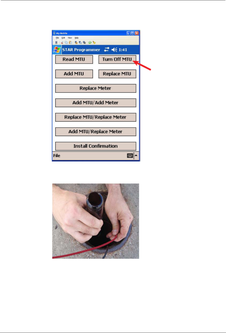
5. Tap Turn Off MTU. Wait for confirmation message that the “MTU has been
successfully turned Off.”
6. Gently pull data logger out of valve chamber by the 1/4" rope (nylon
polypropylene).
20 STAR ZoneScan Technical Manual
STAR ZoneScan MTU Installation Procedure
7. Replace metal valve cover on chamber.
8. Travel to new deployment location and remove existing valve cover from
chamber and set aside. Clean the entire ID and step surface areas with a
steel wire brush to remove any obstructions that would prevent the top of
the new cover from laying even with the top surface of the opening.
9. Proceed to Step 3 of the Installation/Activation Procedure on page 7 and
continue through the remaining steps of the Installation/Activation
Procedure.
STAR ZoneScan Installation
STAR ZoneScan Technical Manual 21
STAR Sync Application Configuration
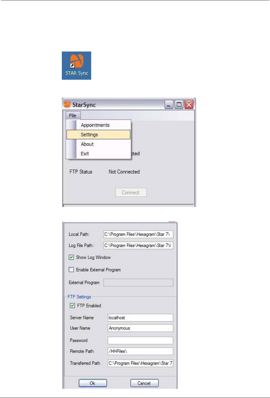
1. Select the STARSync Software on the Start menu or double-clicking on the
STARSync icon on the desktop.
2. Click File and then Settings.
The STARSync Settings window will appear.

22 STAR ZoneScan Technical Manual
STAR Sync Application Configuration
3. Carefully verify the following fields:
•Local Path – C:\Program Files\Hexagram\Star 7\Data\HHfiles\
•Log File Path – C:\Program Files\Hexagram\Star 7\Logs
•Show Log Window check box is selected
•Enable External Program check box is cleared
•FTP Enabled check box is selected
•Server Name – This should be the IP of the NCC server you are
attempting to transfer the files to
•User Name – Anonymous
•Password – This field should be left blank (no password)
•Remote Path – /HHFiles\
•Transferred Path – C:\Program Files\Hexagram\Star 7\Data\
Transferred HHFiles\
4. After verifying these fields click the OK button and then close the
STARSync window
5. Select File and then Exit.
STAR ZoneScan Installation
STAR ZoneScan Technical Manual 23
Uploading Activity Logs to the NCC
The handheld programmer logs information such as account number, meter type,
GPS coordinates, and MTU ID during the original activation of the
STAR ZoneScan MTU and during later reprogramming or reading of the
STAR ZoneScan MTU.
After deploying or redeploying STAR ZoneScan units, it is very important that the
field technician uploads all Activity Logs from the field programmer to the NCC
on the same day that the installation and programming are performed. The upload
process uses the STARSync Software that is installed on a personal computer
configured as a Meter-Shop PC. (See the current version of the STAR Field
Programmer and Software User’s Manual, 471-1001 for details).
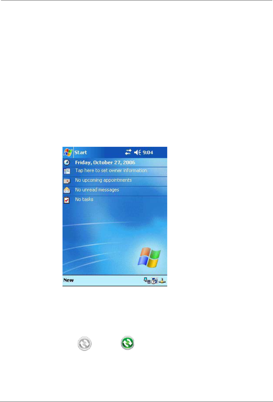
1. Before connecting the field programmer for the activity log upload, make
certain that you have exited the STAR Programmer Software and that the
field programmer is at the Windows handheld Start screen.
2. Connect the field programmer to the designated Meter-Shop PC using a
cable and/or docking station depending on the specific field programmer
configuration you are using.
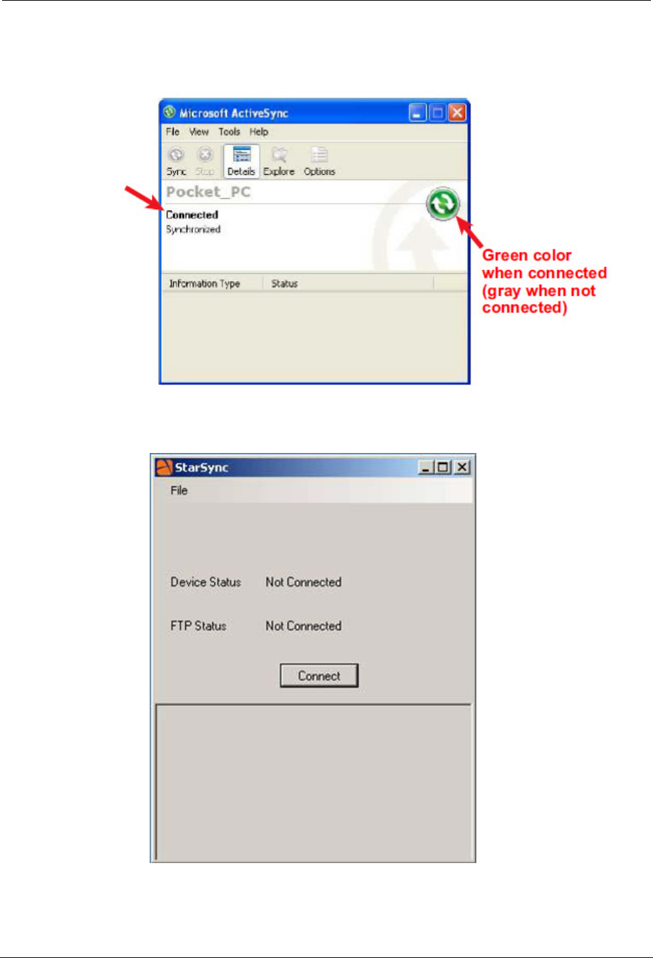
3. Verify that the field programmer is recognized by the PC by checking that
the ActiveSync icon in the system tray has changed from
gray to green . This indicates that the field programmer is
properly connected and recognized by ActiveSync.
24 STAR ZoneScan Technical Manual
Uploading Activity Logs to the NCC
The ActiveSync interface will also open and indicate when the field programmer is
connected.
4. Double-click on the STARSync icon on the Meter-Shop PC desktop to open
the STARSync application.
STAR ZoneScan Installation
STAR ZoneScan Technical Manual 25
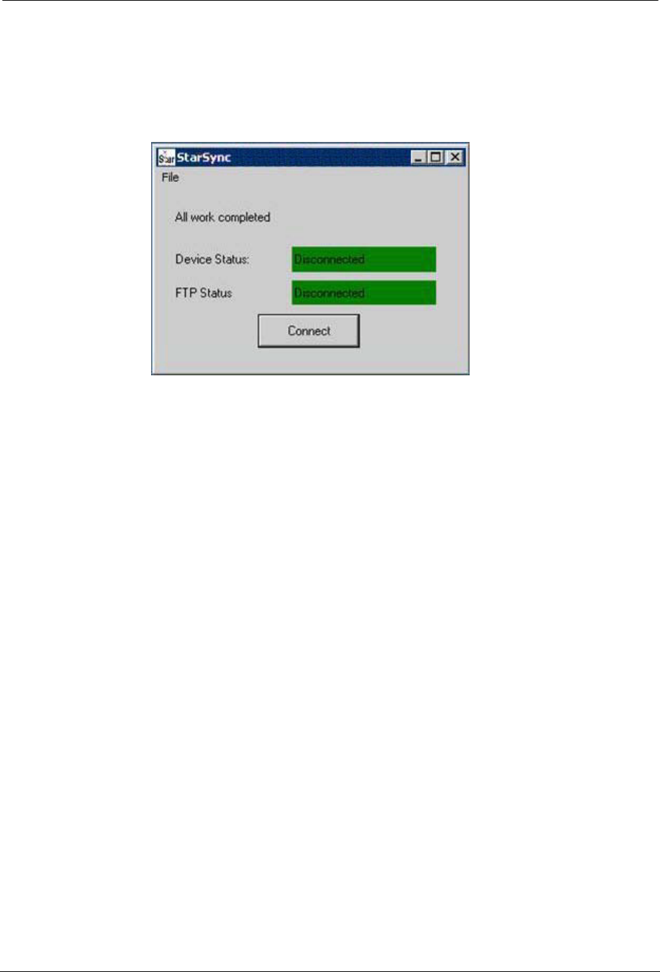
5. Click on the Connect button and the field programmer will upload all
Activity Logs to the remote PC for transfer to the NCC. When the upload
transfer is complete, the message All work completed, Device Status:
Disconnected, and FTP Status Disconnected will be shown. The next field
programmer can be docked and the process can be repeated as necessary.
N
OTE
If any changes or updates have been made to the field programmer XML
configuration files on the NCC, these changes will be downloaded to the field
programmer at this time.

26 STAR ZoneScan Technical Manual
Uploading Activity Logs to the NCC
STAR ZoneScan Technical Manual 27
CHAPTER
2
STAR Z
ONE
S
CAN
O
PERATION
Purpose & Scope
This instruction will describe the procedures for the operation of STAR ZoneScan
leak detection MTUs.
What You’ll Learn
Tasks covered in this chapter include how to:
• Monitor STAR ZoneScan data collection
• Change Trigger DCU
• Connect to Gutermann ZoneScan net website to identify potential leak
locations
28 STAR ZoneScan Technical Manual
STAR ZoneScan System Operation
STAR ZoneScan System Operation
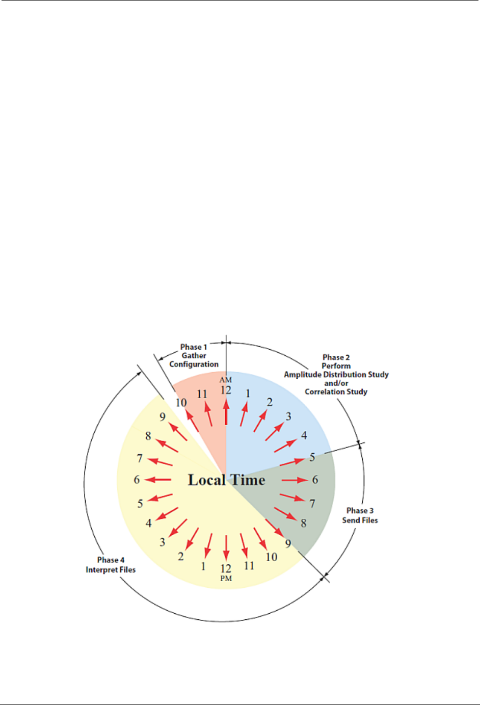
The STAR ZoneScan leak detection system operates in a 24-hour cycle according
to four distinct phases.
The four phases are:
1. MTU gathers new configuration parameters for the ZoneScan data loggers.
2. Performs recordings (always perform an Amplitude Distribution Study and
possibly a Correlation Study. Please see Recording Data on page 29)
3. Sends files from ZoneScan data loggers to NCC.
4. User interprets data and may modify configuration parameters.
In order for the STAR ZoneScan leak detection system to work properly, each of
the four phases must be performed in order according to a 24-hour cycle. The time
when the phases begin and end may vary, however, they must all be completed
within a period of 24 hours.
N
OTES
Phase 1 always begins at 10:00 p.m. and ends at 12:00 midnight local time.
Phase 2 must end by 8:00 a.m. local time.
STAR ZoneScan Operation
STAR ZoneScan Technical Manual 29
Recording Data
All Gutermann Model 820 data loggers perform a nightly Amplitude Distribution
study consisting of a decibel reading every 10 seconds over a two-hour window..
Amplitude Distribution Study
An Amplitude Distribution Study is a two-hour recording performed each day
by all Gutermann Model 820 data loggers.
Correlation Study
A Correlation Study is a time-synchronized 12 second recording performed by
selected data loggers to pinpoint suspected leaks.
Viewing STAR ZoneScan Data
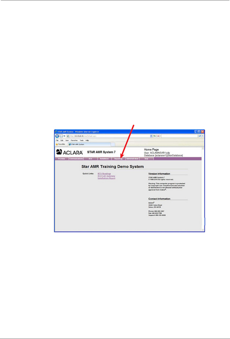
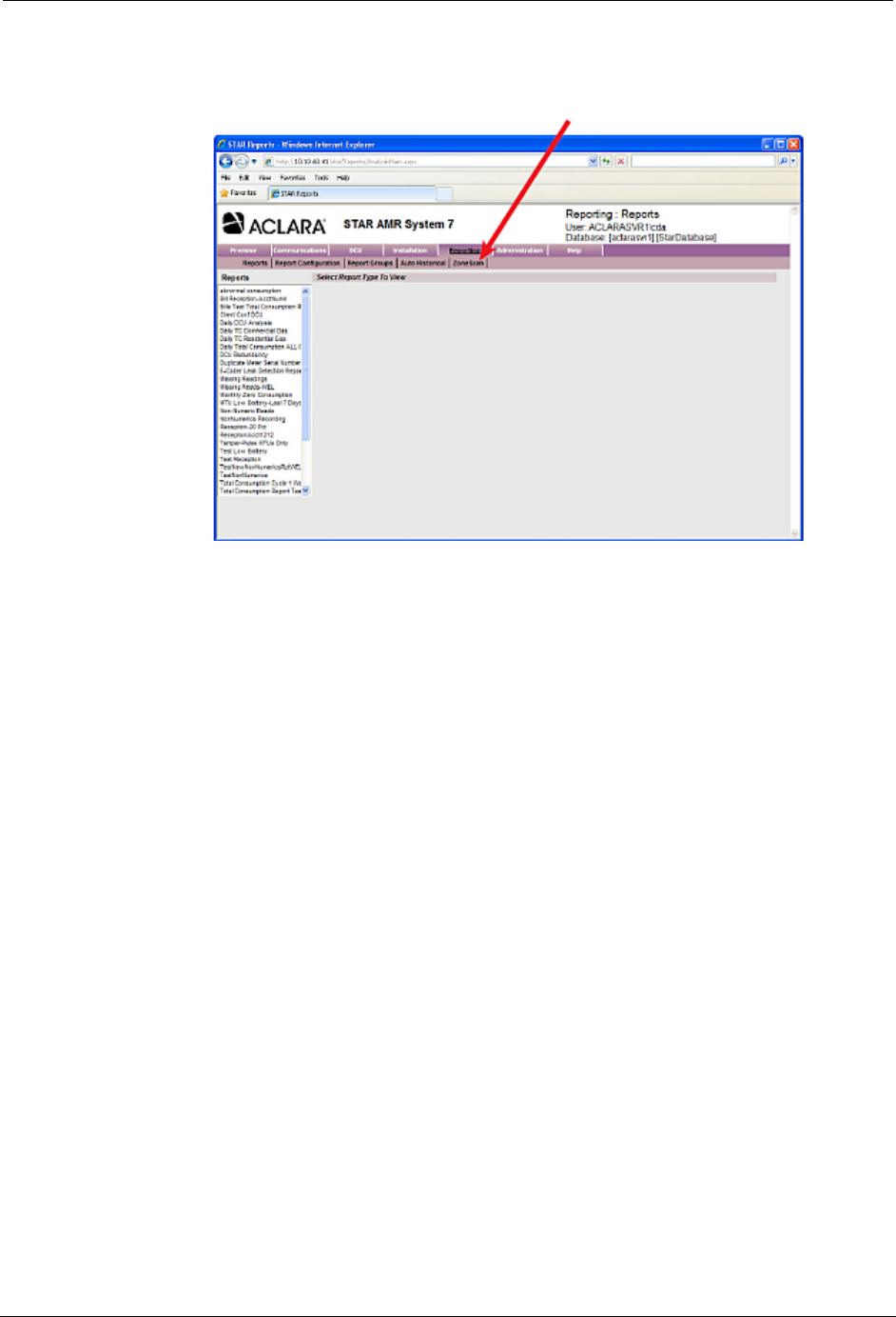
1. Click the Reporting tab, from the NCC STAR Home Page.
30 STAR ZoneScan Technical Manual
STAR ZoneScan System Operation
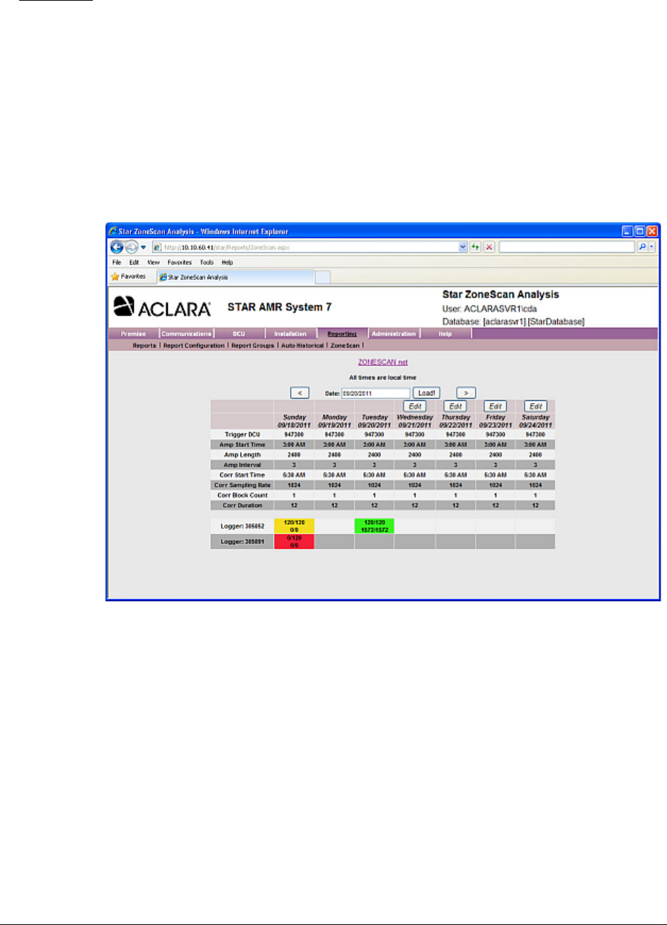
2. Click ZoneScan, from the Reporting menu. The ZoneScan screen will
display data for the current week.
.
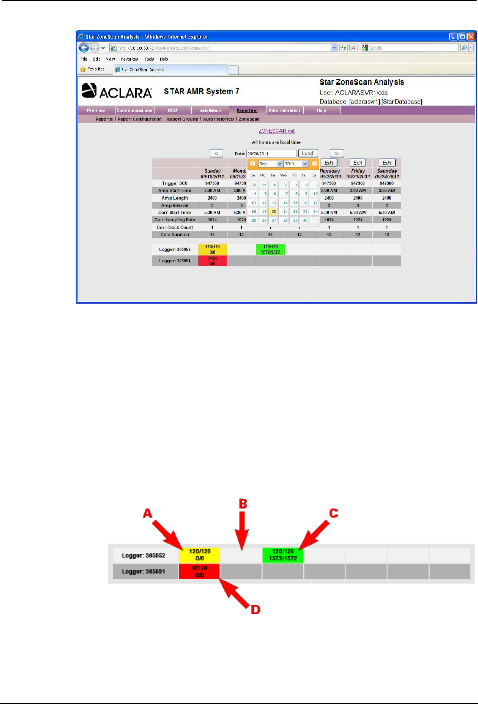
3. Click inside the Date field to select the desired date and then click the
Load! button.
N
OTE
Use the < button to go back one week, or the > sign to go forward one week.
STAR ZoneScan Operation
STAR ZoneScan Technical Manual 31
4. Data results will be displayed in four different colors :
AYellow = Amplitude data was successfully received with no
Correlation data.
BBlank = No recordings exist for this logger on this day.
CGreen = Both the Amplitude and Correlation data were successfully
received
DRed = Either the Amplitude data or Correlation data is missing
critical packets.
N
OTE
STAR ZoneScan study parameters are automatically preset each day. Except
for the Trigger DCU, there is no need to change any of these parameters under
normal operating conditions.
32 STAR ZoneScan Technical Manual
STAR ZoneScan System Operation
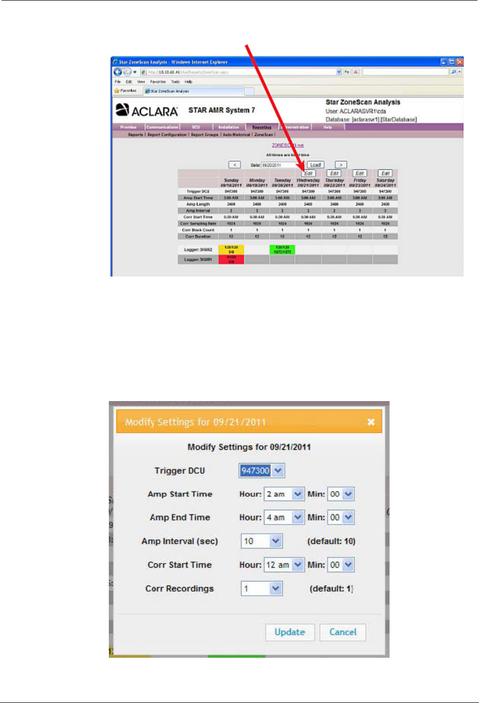
5. Click the Edit button to access the Modify Settings window.
The Trigger DCU is defined as that DCU which sends out a start recording
signal to initiate correlation recordings. Only STAR ZoneScan MTUs that
receive the signal will perform the correlation recording. The Trigger DCU
will automatically rotate among all designated DCUs in the system. No
operator action is required.
6. To select a specific Trigger DCU, On the Modify Settings window, use the
Trigger DCU drop-down menu to select the desired Trigger DCU. Leave
all the remaining settings at their default values.
7. Click the Update button.
STAR ZoneScan Operation
STAR ZoneScan Technical Manual 33
Connecting to Gutermann ZoneScan net website
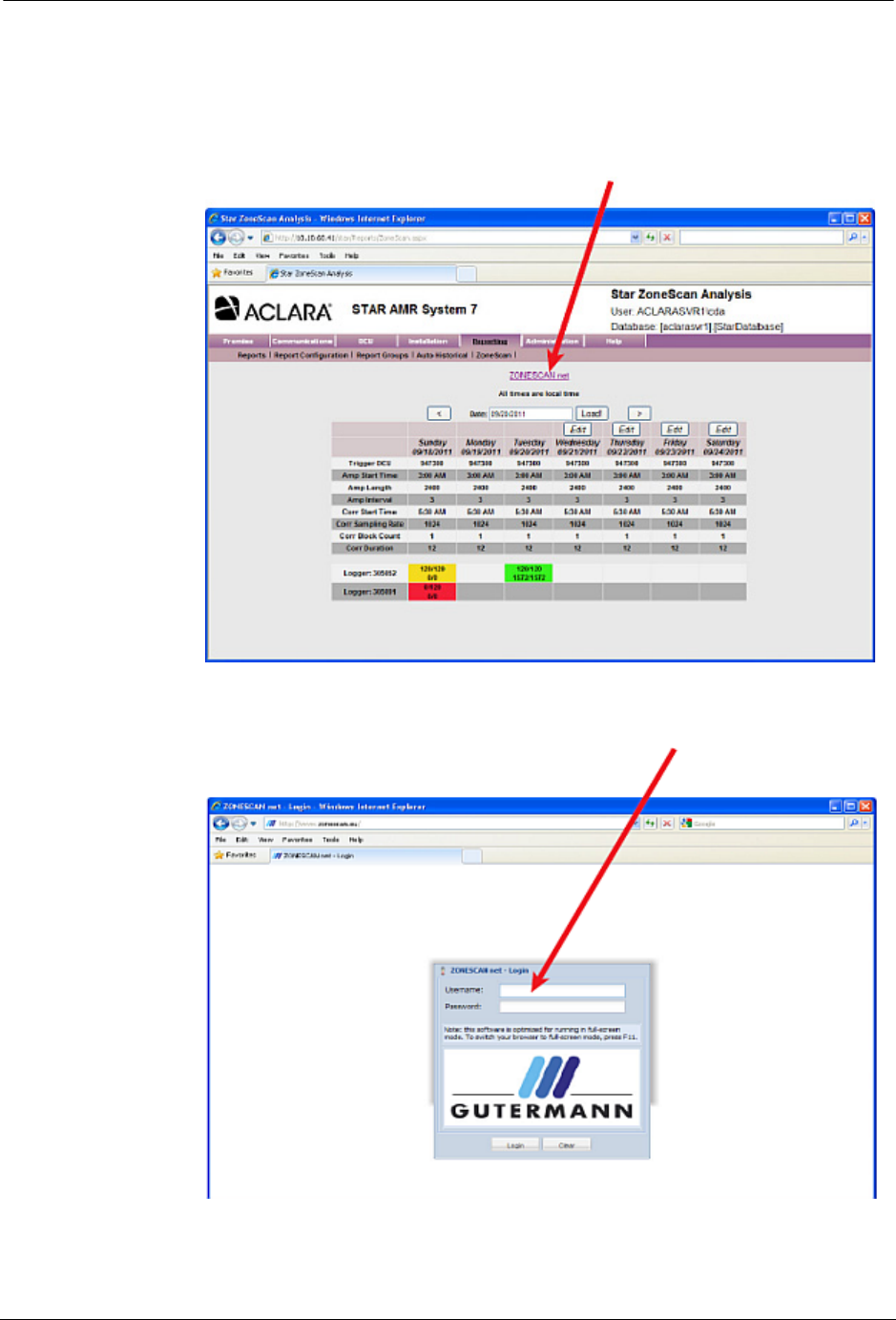
1. Select Reporting>ZoneScan.
2. Click the ZONESCAN net link.
3. The ZONESCAN net - Login page appears in a new browser window. Enter
your credentials in the Username and Password fields.
4. Click in the Login button.
34 STAR ZoneScan Technical Manual
STAR ZoneScan System Operation
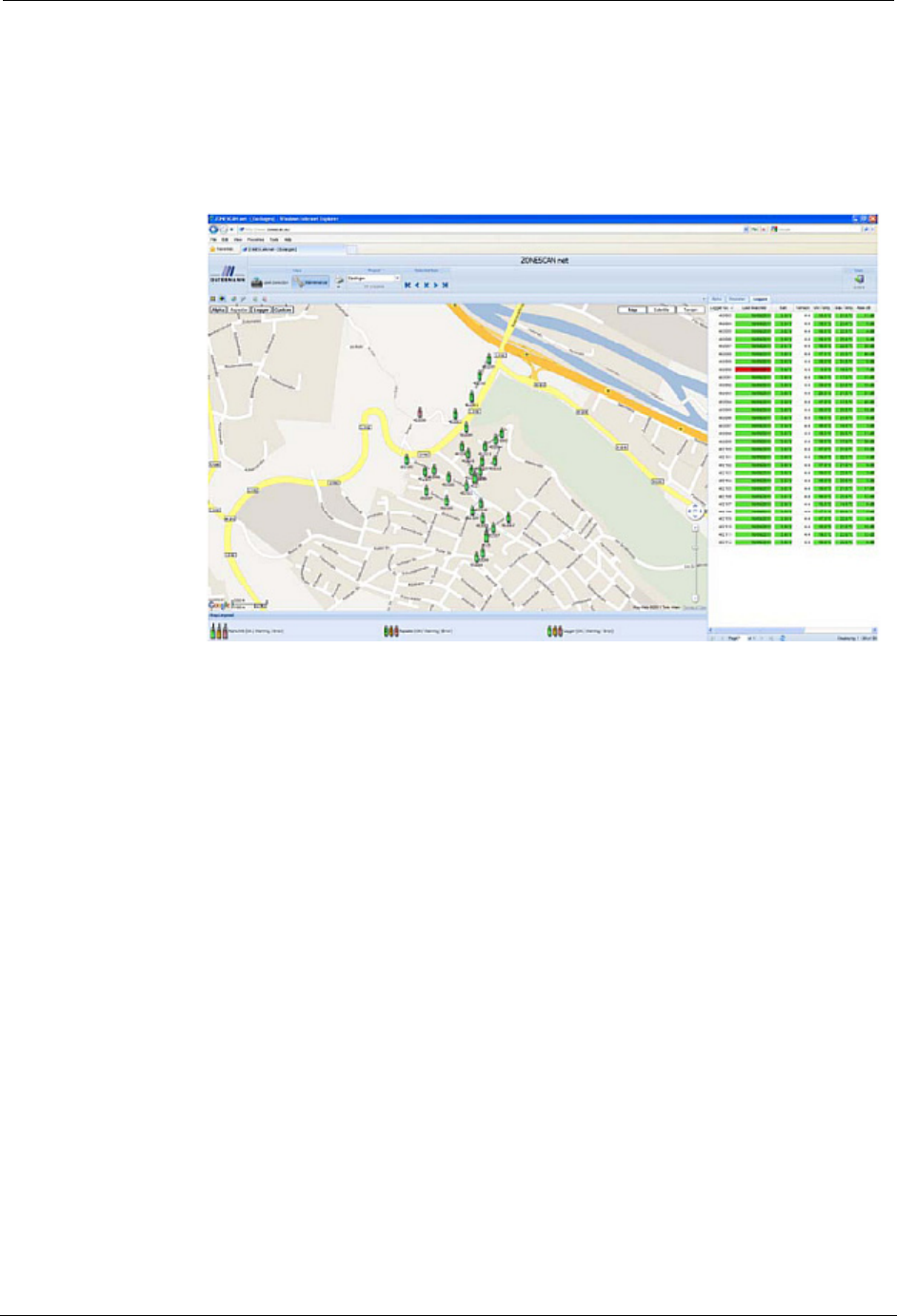
5. The Gutermann ZONESCAN net page appears in the browser. Select your
project from the Project drop-down window.
N
OTE
A new project must be created when STAR ZoneScan MTUs are redeployed.
6. Refer to the Gutermann ZoneScan net Operation Manual, Version 1.4, for
data entry and interpretation beginning in Section 1.3.