Aclara Technologies 2017017 ZoneScan II-Meter Transmitting Unit User Manual
Aclara Technologies LLC ZoneScan II-Meter Transmitting Unit
User Manual


ZoneScan II Field Installation Instructions
2 | P a g e
Proprietary Notice
This document contains information that is private to Aclara Technologies LLC, an Ohio limited
liability company, and/or that is private to Aclara Meters LLC, a Delaware limited liability
company (individually or collectively “Aclara”). This information may not be published,
reproduced, or otherwise disseminated without the express written authorization of Aclara.
Any software or firmware described in this document is furnished under a license and may be
used or copied only in accordance with the terms of such license.
Disclaimer
The information in this document is subject to change without notice and should not be
construed as a commitment by Aclara. Aclara assumes no responsibility for any errors that may
appear in this document.
No responsibility is assumed for the use or reliability of software on equipment that is not
supplied by Aclara.
Metrum Cellular, STAR, Synergize, and TWACS are registered trademarks of Aclara
Technologies LLC.
Aclara Technologies LLC
Confidential and Proprietary
Copyright 2018. All Rights Reserved.
ZoneScan II Field Installation Instructions
3 | P a g e
STAR ZoneScan II Assembly
Configuration and Installation Instructions (Y63158-TUM-Rev A)
______________________________________________________________________________
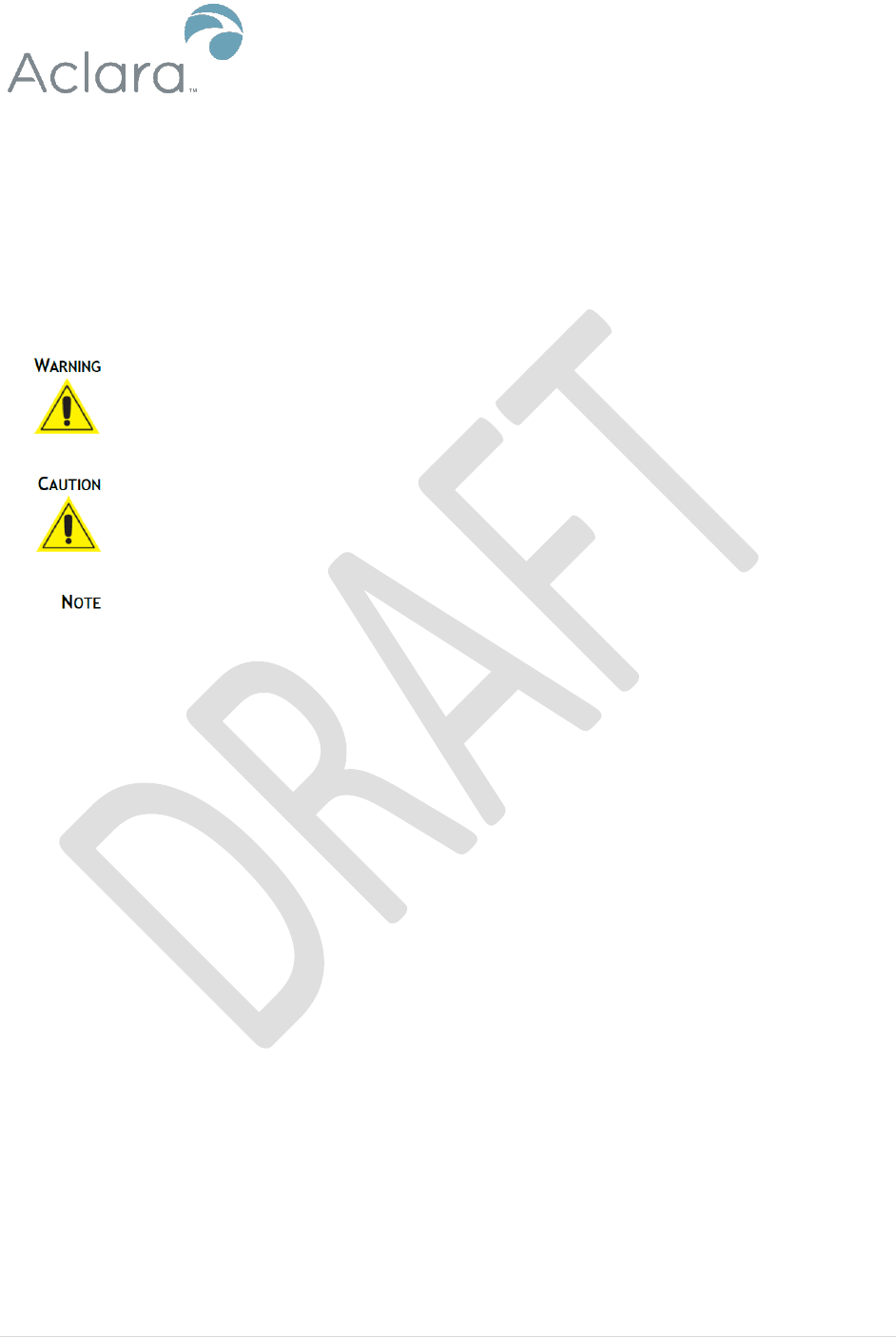
Warnings, Cautions and Notes
Always consult and adhere to all local and national safety codes, regulations, and standards.
WARNING, CAUTION and Note statements are used throughout this manual to emphasize
important and critical information to help you ensure safety and prevent product damage. These
statements are defined below.
Indicates a potentially hazardous situation which, if not avoided, could result in
death or serious physical injury.
Indicates a situation, which, if not avoided, could result in damage to equipment,
damage to software, loss of data or invalid results.
Indicates important supplemental information.
FCC/IC Compliance
This equipment has been tested and found to comply with the limits for a Class B digital device,
pursuant to part 15 of the FCC Rules. These limits are designed to provide reasonable protection
against harmful interference in a residential installation. This equipment generates, uses and can
radiate radio frequency energy and, if not installed and used in accordance with the instructions,
may cause harmful interference to radio communications. However, there is no guarantee that
interference will not occur in a particular installation. If this equipment does cause harmful
interference to radio or television reception, which can be determined by turning the equipment
off and on, the user is encouraged to try to correct the interference by one or more of the
following measures:
• Reorient or relocate the receiving antenna.
• Increase the separation between the equipment and receiver.
• Connect the equipment into an outlet on a circuit different from that to which the receiver
is connected.
• Consult the dealer or an experienced radio/TV technician for help.
Any changes or modification made to this device without the expressed, written approval of
Aclara Technologies LLC may void the user's authority to operate this device.

ZoneScan II Field Installation Instructions
4 | P a g e
Antennas
Only the antenna provided with this meter is authorized to be used without approval from Aclara,
the FCC, and ISED.
FCC/IC RF Exposure Guide
Aclara Technologies LLC low power RF devices and their antennas must be fixed-mounted on
indoor or outdoor permanent structure(s) providing a separation distance of at least 20 cm from
all persons during normal operation. This device is not designed to operate in conjunction with
any other antennas or transmitters. No other operating instructions for satisfying RF exposure
compliance are needed.
Field Calibration Procedure
Aclara Technologies LLC low power RF devices have passed through extensive testing and
calibration procedures while in the factory. Therefore, no additional calibration or adjustment is
required in the field.
ZoneScan II Field Installation Instructions
5 | P a g e
Avertissements, mises en garde et remarques
Toujours consulter et respecter les codes, règlements et normes de sécurité locaux et nationaux.
Des AVERTISSEMENTS, MISES EN GARDE et remarques sont utilisés tout au long de ce
guide pour souligner l'information importante et critique qui vous aidera à assurer la sécurité et à
prévenir les dommages au produit. Ces énoncés sont définis ci-dessous.
Indique une situation potentiellement dangereuse qui, si elle n'était pas évitée,
pourrait entraîner la mort ou des blessures graves.
Indique une situation qui, si elle n'était pas évitée, pourrait entraîner des
dommages à l'équipement, des dommages au logiciel, des pertes de données ou
des résultats invalides.
Indique des informations supplémentaires importantes.
Conformité FCC/IC
Cet équipement a été testé et il est conforme aux limites pour un appareil numérique de Classe B,
en vertu de l'article 15 des règlements de la FCC. Ces limites sont conçues pour offrir une
protection raisonnable contre l'interférence nuisible dans une installation résidentielle. Cet
équipement génère, utilise et peut émettre de l'énergie de fréquences radio et, s'il n'est pas installé
ou utilise conformément aux instructions, il peut causer une interférence nuisible aux
communications radio. Il n'existe toutefois aucune garantie que de tels interférences ne se
produiront pas dans une installation particulière. Si cet appareil cause des interférences nuisibles
à la réception des signaux de radio ou de télévision, ce qui peut être détecté en mettant l'appareil
sous et hors tension, l'utilisateur peut tenter de neutraliser l'interférence de l'une ou l'autre des
façons suivantes :
• Réorienter ou repositionner l'antenne de réception.
• Augmenter la distance séparant l'équipement du récepteur.
• Brancher l'appareil dans une prise sur un circuit électrique différent de celui sur lequel le
récepteur est branché.
• Consulter le fournisseur ou un technicien radio ou télévision expérimenté.
Tout changement ou toute modification à cet appareil sans l'approbation écrite expresse d'Aclara
Technologies LLC peut annuler l'autorisation de l'utilisateur d'utiliser cet appareil.

ZoneScan II Field Installation Instructions
6 | P a g e
Antennes
L'antenne fournie avec ce compteur est la seule qui puisse être utilisé sans l'approbation
d’Aclara, the FCC et l’ISED.
Guide d'exposition aux RF FCC/IC
Les appareils RF à faible puissance Aclara Technologies LLC ainsi que leurs antennes doivent
être montés de manière fixe sur des structures intérieures ou extérieures permanentes qui se
trouvent à au moins 20 cm des personnes pendant le fonctionnement normal. Cet appareil n'est
pas conçu (et il n'a aucun branchement externe) pour être utilisé en association avec toute autre
antenne ou tout transmetteur. Aucune autre instruction d'utilisation n'est requise pour assurer la
conformité aux règles d'exposition aux RF.
Procédure de calibration sur place
Les appareils RF à faible puissance Aclara Technologies LLC ont été soumis à des tests étendus
et multi-tâches et à des procédures de calibration complexes en usine. Par conséquent, ils ne
requièrent pas de calibration ni d'ajustement supplémentaire sur place. Les appareils RF à faible
puissance Aclara Technologies LLC sont expédiés au client dans des boîtiers scellés. Aucun
ajustement ne peut donc être effectué sur place sans briser le boîtier scellé en usine.
ZoneScan II Field Installation Instructions
7 | P a g e
Introduction
Use these instructions to install a ZoneScan II Assembly. For more information on ZoneScan
leak detection, please refer to the following documents:
MTU Installation Requirements (Y20355-TEB) This technical brief provides
information about RF signal transmission as well as approved practices for TU
installations.
ZoneScan Technical Manual (Y20284-TUM) The technical manual provides
information about acoustic leak detection and monitoring ZoneScan data.
Commissioning Document (obtain document from Ralph W.)
If, at any time, you would like to speak with a Aclara representative about any product or
service, please contact Support at support@aclara.com or by calling 1-800-892-9008.
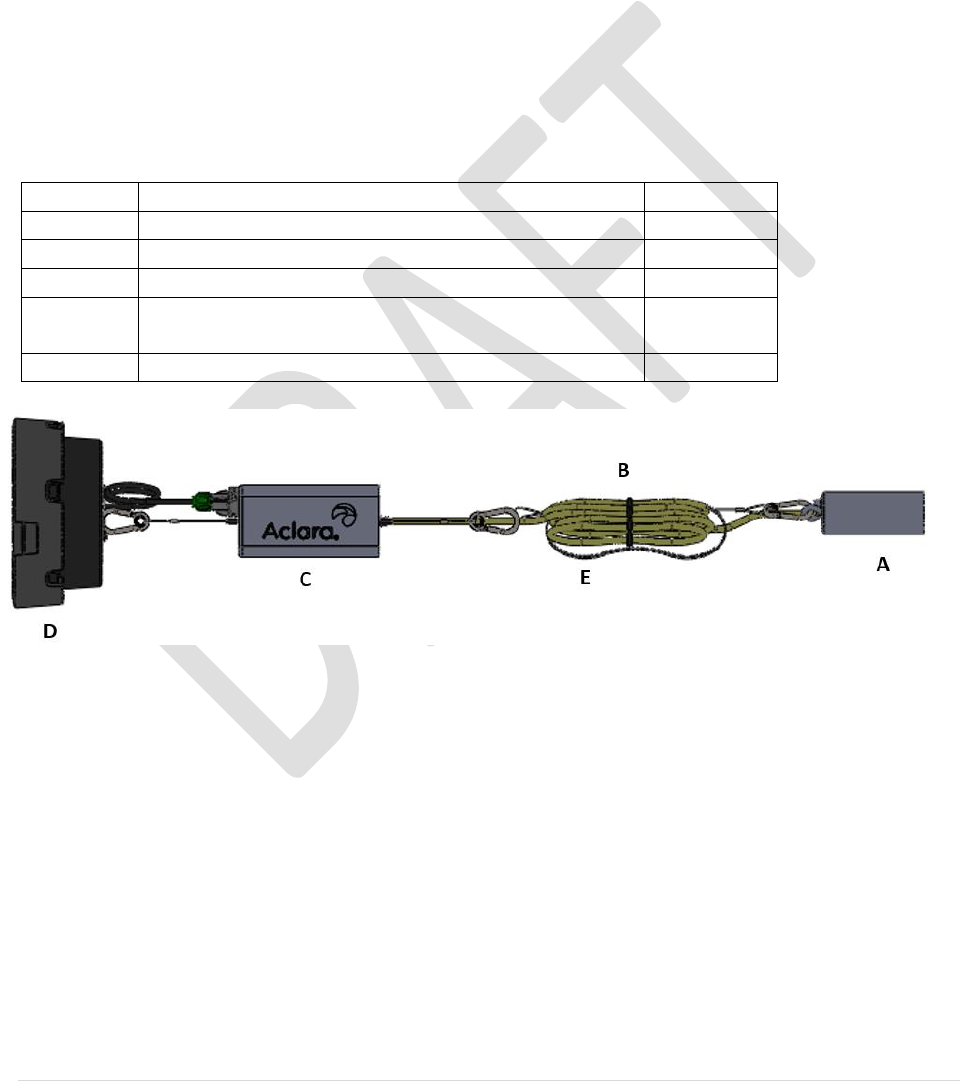
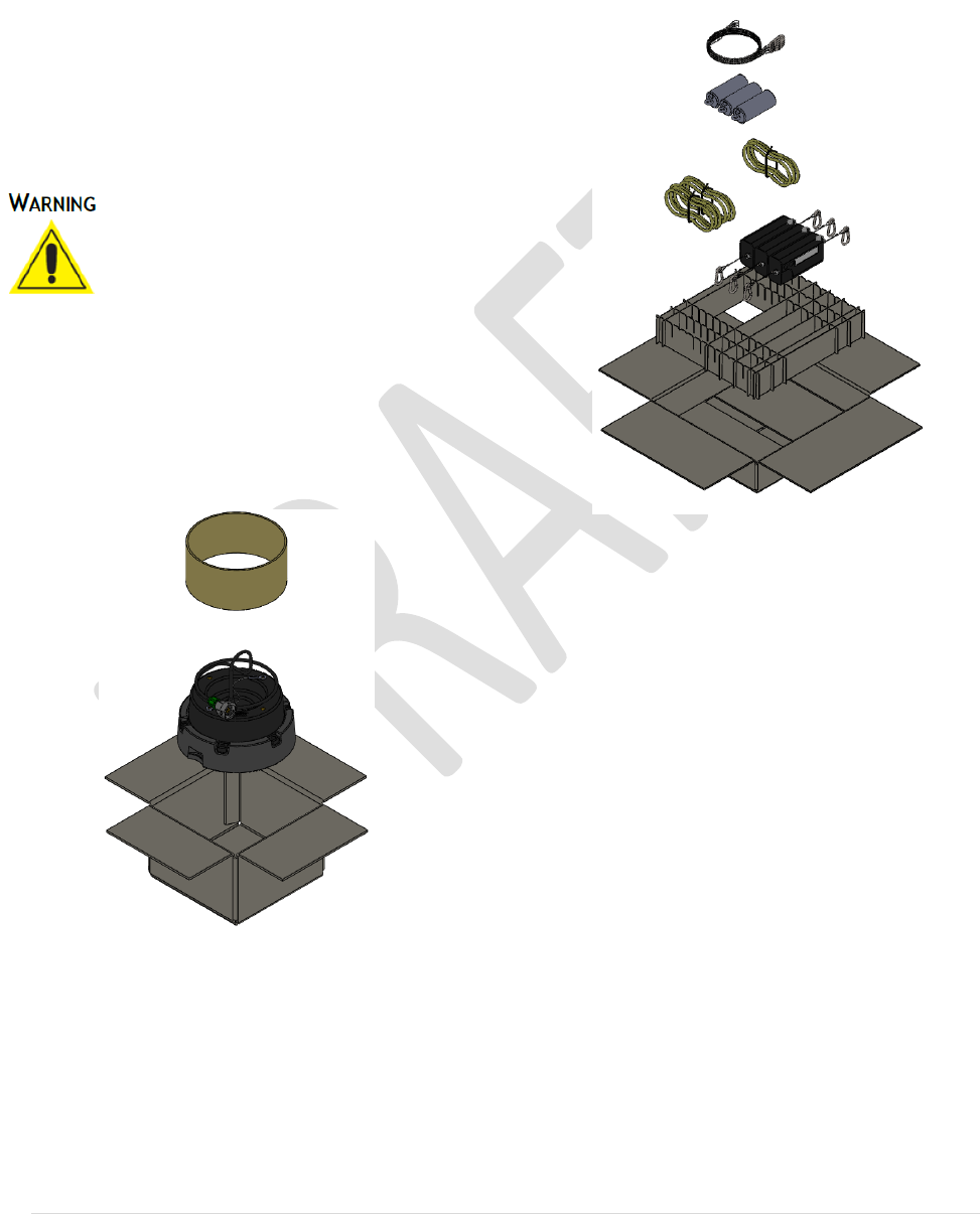
ZoneScan II Assembly Kit
Item
Description
Quantity
A
ZoneScan 820 Sensor
1
B
Communication Cable
1
C
Transmission Unit
1
D
7 ¼” Non-Metallic Valve Lid / Antenna
Assembly
1
E
6-foot Lanyard
1
ZoneScan II Field Installation Instructions
8 | P a g e
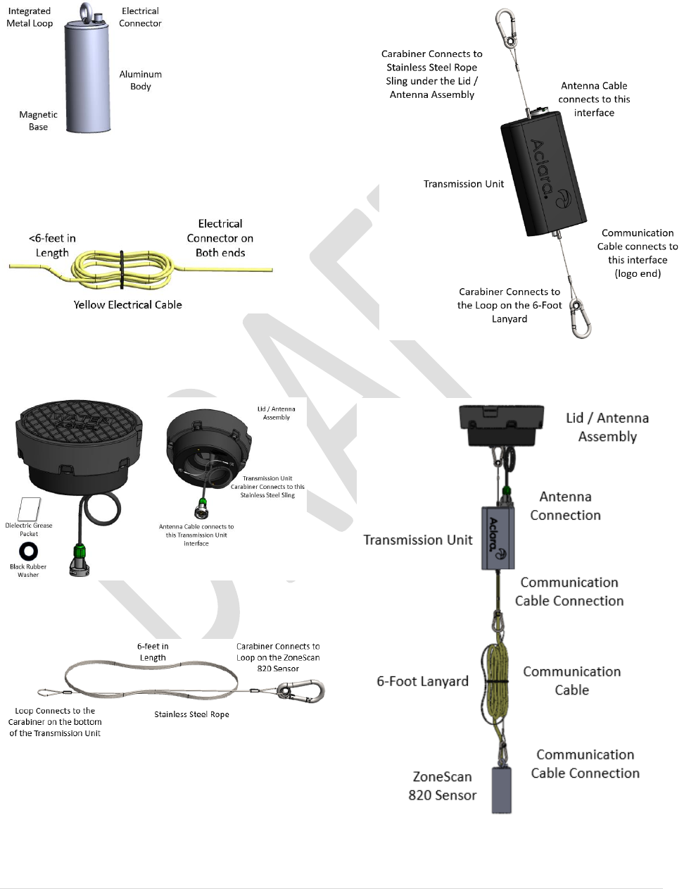
Identification
ZoneScan 820 Sensor
Communication Cable
7 ¼” Non-Metallic Valve Lid /
Antenna Assembly
6-foot Lanyard
Transmission Unit
Completed Assembly
ZoneScan II Field Installation Instructions
9 | P a g e
Tools/Equipment Required
Magnet
Torque Wrench (break over at 5-inch
pounds)
Measuring Tape (10-feet minimum)
Flashlight
Appropriate personal protective
equipment (PPE)
Deployment of the ZoneScan II
System is typically performed in the
road. Great care must be taken to
protect the worksite and the workers.
Installation Instructions
A. The unit should be assembled as close as
possible to the deployment location (best
to not assemble in the meter shop).
B. Unpack the Valve Lid/Antenna
Assembly
C. Unpack ZoneScan II Transmission Unit
and ZoneScan Sensor, Communication
Cable and 6’ Lanyard
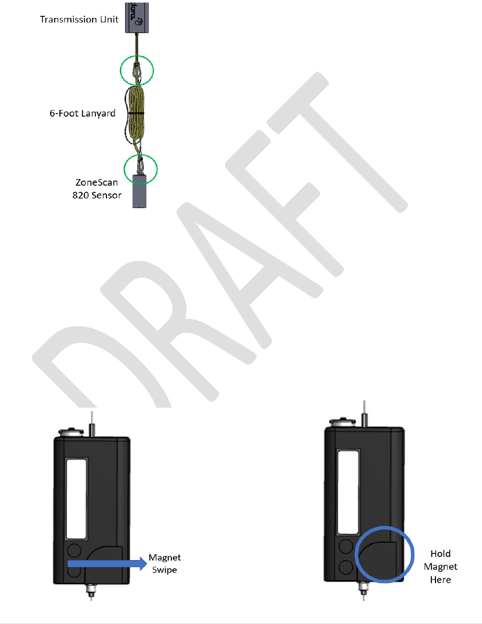
D. Connect the top lanyard (away from the
logo) on MTU to stainless steel sling
under the lid
E. Place the provided dielectric grease into
female connector
F. Place the rubber washer in antenna
connector boot
G. Connect antenna cable to MTU (torque
to 5 inch-pounds). Wipe or clean excess
grease.
H. Tighten boot hand-tight on antenna
connector. Tighten sealing nut to boot
ensuring rubber piece is seated.
I. Measure the distance from the road or
ground surface to the top of valve nut
and determine if extension needed. An
extension will be needed if the distance
is greater than 7-feet.
ZoneScan II Field Installation Instructions
10 | P a g e
J. Connect 6-foot Lanyard to bottom
carabiner of Transmission Unit (with
extension if necessary) to the loop on the
ZoneScan 820 Sensor.
K. Connect Communication Cable to
ZoneScan 820 Sensor and the
Transmission Unit (add another
Communication Cable if required from
Step I)
L. Orient the Lid / Antenna Assembly
facing toward the sky (Aclara logo
facing up)
M. Swipe the magnet once, wait for LEDs
to light and swipe magnet a second time
within 15 seconds to begin
commissioning. The green light will
come on and stay on for 15 seconds to
confirm commissioning was successful.
N. Carry the fully assembled ZoneScan II
Unit to the valve stack
O. Place the ZoneScan 820 Sensor into the
valve stack first making sure it connects
to valve nut and continue to lower the
Unit into the valve stack until the Unit is
in place with the Lid / Antenna
Assembly in the place of the original
metal lid.
IMPORTANT! The 7 ¼” Non-Metallic
Valve Lid / Antenna Assembly is designed
to accommodate RF transmissions. DO NOT
paint or otherwise alter the Non-Metallic
Valve Lid.
Decommissioning
The ZoneScan II System should be
decommissioned prior to removal from the
site or redeployment. To decommission the
Unit:
1. Remove the ZoneScan II unit from
the from the valve stack and move to
a safe location.
2. Replace the cast iron valve lid
3. Hold the magnet over the area shown
below for a couple of seconds to

ZoneScan II Field Installation Instructions
11 | P a g e
return to ship mode (a slow flashing
red light on LEDs).
To redeploy the ZoneScan II Unit, proceed
to Step M above.
Repackaging
To repackage the unit:
I. Disconnect yellow Gutermann
cable from logger and MTU.
II. Disconnect carabiner from 6-foot
lanyard.
III. Disconnect 6-foot lanyard from
top of logger.
IV. Disconnect carabiner from
stainless steel sling under the lid
assembly.
V. Disconnect boot from MTU by
loosening the sealing nut and
boot. Remove rubber washer.
VI. Disconnect SMA antenna
connector from MTU.
VII. Clean dielectric grease from
antenna cable and connector on
MTU.