Aclara Technologies 2017023 American Commercial Gas MTU User Manual Y20969 TUM
Aclara Technologies LLC American Commercial Gas MTU Y20969 TUM
User Manual

1
Elster / AMCO Gas Meter MTU Installation Instructions
Elster / AMCO Gas Meter
MTU Installation Instructions (Y20969-TUM Rev A)
FCC/ISED Compliance
This product/device has been tested and certified to be in compliance with all appropriate requirements
of both the FCC and ISED.
Any changes or modification to this product/device, or the use of any antenna other than the one
provided by or authorized with expressed written approval by Aclara Technologies LLC may void the
user's authority to operate this product/device.
This product/device and/or its antenna must be fixed-mounted on indoor or outdoor permanent
structure(s) providing a separation distance of at least 20 cm from all persons during normal operation.
This device is not designed (and it has no external connection) to operate in conjunction with any other
antennas or transmitters. No other operating instructions for satisfying RF exposure compliance are
needed.
This product/device has been tested and calibrated at the factory. It has no user adjustable controls and
can only be adjusted by authorized, trained personnel.
French translation
Conformité FCC/ISDE
Cet équipement a été testé et il est conforme à toutes les exigences appropriées de la FCC et de l'ISDE.
Tout changement ou toute modification à cet appareil, ou l'emploi de n'importe quelle antenne autre
que celle fournie par ou autorisée sous l'accord exprès donné par écrit d'Aclara Technologies LLC peut
annuler l'autorisation d'utiliser de cet appareil.
Cet appareil ainsi que son antenne doivent être montés de manière fixe sur des structures intérieures ou
extérieures permanentes en conférant une distance d'au moins 20 cm des personnes pendant le
fonctionnement normal. Cet appareil n'est pas conçu (et il n'a aucun branchement externe) pour être
utilisé en association avec toute autre antenne ou tout émetteur. Aucune autre instruction d'utilisation
n'est requise pour assurer la conformité aux règles d'exposition aux RF.
Cet appareil a été soumis à des tests et calibré en usine. Il n'a pas de contrôle d'ajustement et ne peut
être ajusté que par un personnel autorisé et qualifié.
This document contains information that is private to Aclara Technologies LLC, an Ohio limited liability company, and/or that is private to
Aclara Meters LLC, a Delaware limited liability company (individually or collectively “Aclara”). This information may not be published,
reproduced, or otherwise disseminated without the express written authorization of Aclara. Any software or firmware described in this document
is furnished under a license and may be used or copied only in accordance with the terms of such license. The information in this document is
subject to change without notice and should not be construed as a commitment by Aclara. Aclara assumes no responsibility for any errors that
may appear in this document. No responsibility is assumed for the use or reliability of software on equipment that is not supplied by Aclara.
Metrum Cellular, STAR, Synergize, and TWACS are registered trademarks of Aclara. 2011-2017. All Rights Reserved. Confidential and
proprietary.
2
Elster / AMCO Gas Meter MTU Installation Instructions
Purpose & Scope
This instruction provides a procedure for installing an Aclara STAR MTU on Elster/American
Commercial Models: 60B, 80B, AL-800, AL-1000, AL-1400, AL-2300, and AL-5000 Industrial &
Commercial Turbine Rotary Gas Meters. This installation instruction covers the Aclara Catalog
number 3571-015-RBS2 and 3571-015-RBS2W for these gas meters. (The images in this document are for
reference only.)
Parts Required
N
OTE
The mounting kit contains the exact quantity of hardware required for a single installation. Keep
extra hardware on hand.
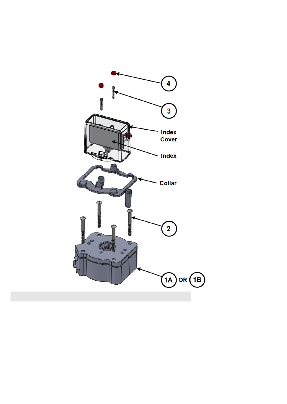
#Item Qty
1 MTU, GAS, OD2, DIR, AMCOM, STDRNG 1
OR
1 MTU, GAS, OD2, DIR, AMCOM, EXTRNG 1
2 #18-18 X 3 1/8" Screw, SS 4
3 #10-32 X 1" Screw, SS 2
4 Gas MTU security seal 2
3
Elster / AMCO Gas Meter MTU Installation Instructions
NOTE
No repair or maintenance of MTU is required. Defective MTU will be replaced.
NOTE
MTU may be wiped with damp cloth to prevent electrostatic charge hazard.
Tools Required
To connect the MTU to these meters, you will need the following tools and equipment:
• #2 Phillips screwdriver
• 1/4" Slotted screwdriver
• Torque-limiting screwdriver
• Safety glasses
Remove Index and Baseplate
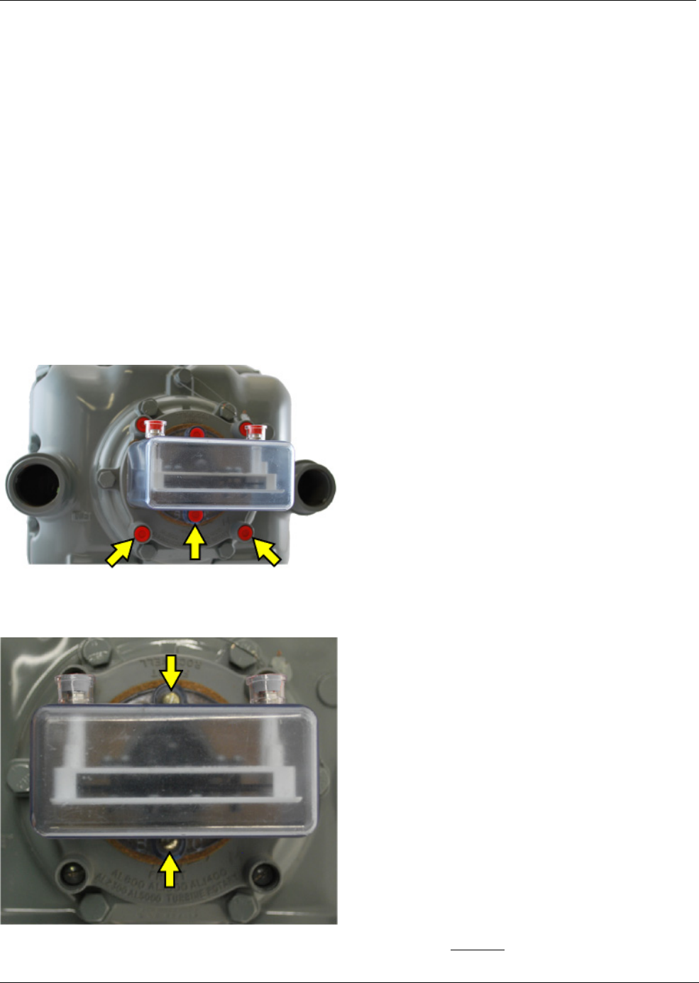
1. Remove the anti-tamper, safety, and security hardware from the screws attaching the index cover
and baseplate to the meter.
2. Remove the index cover and index by removing the two screws securing it to the meter. Discard the
screws.
NOTE: If any of the screws are broken, or break during removal, DO NOT install the MTU.
4
Elster / AMCO Gas Meter MTU Installation Instructions
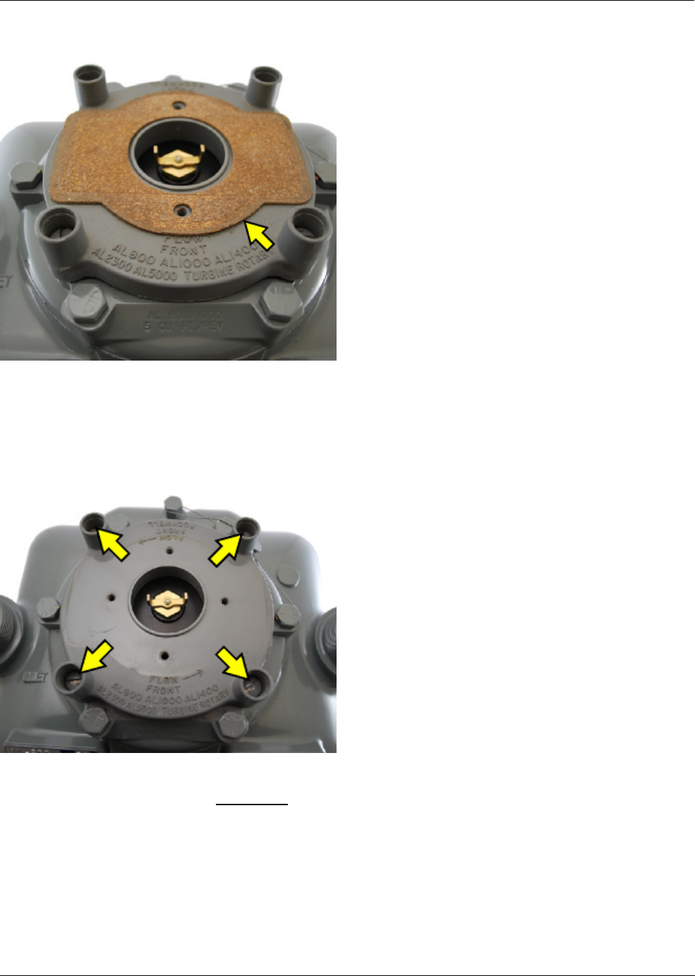
3. Remove and retain the gasket..
NOTE: In addition to the gasket shown, some index covers use a silicone gasket. In this case, ensure
that the silicone gasket remains attached to the index cover and is not damaged.
4. Remove the four screws securing the baseplate to the meter. Discard the base plate.
NOTE: If more than two screws are broken, or if two screws are broken and they are not on opposite
diagonal sides, the MTU should not be installed.
5
Elster / AMCO Gas Meter MTU Installation Instructions
Mount MTU to Meter
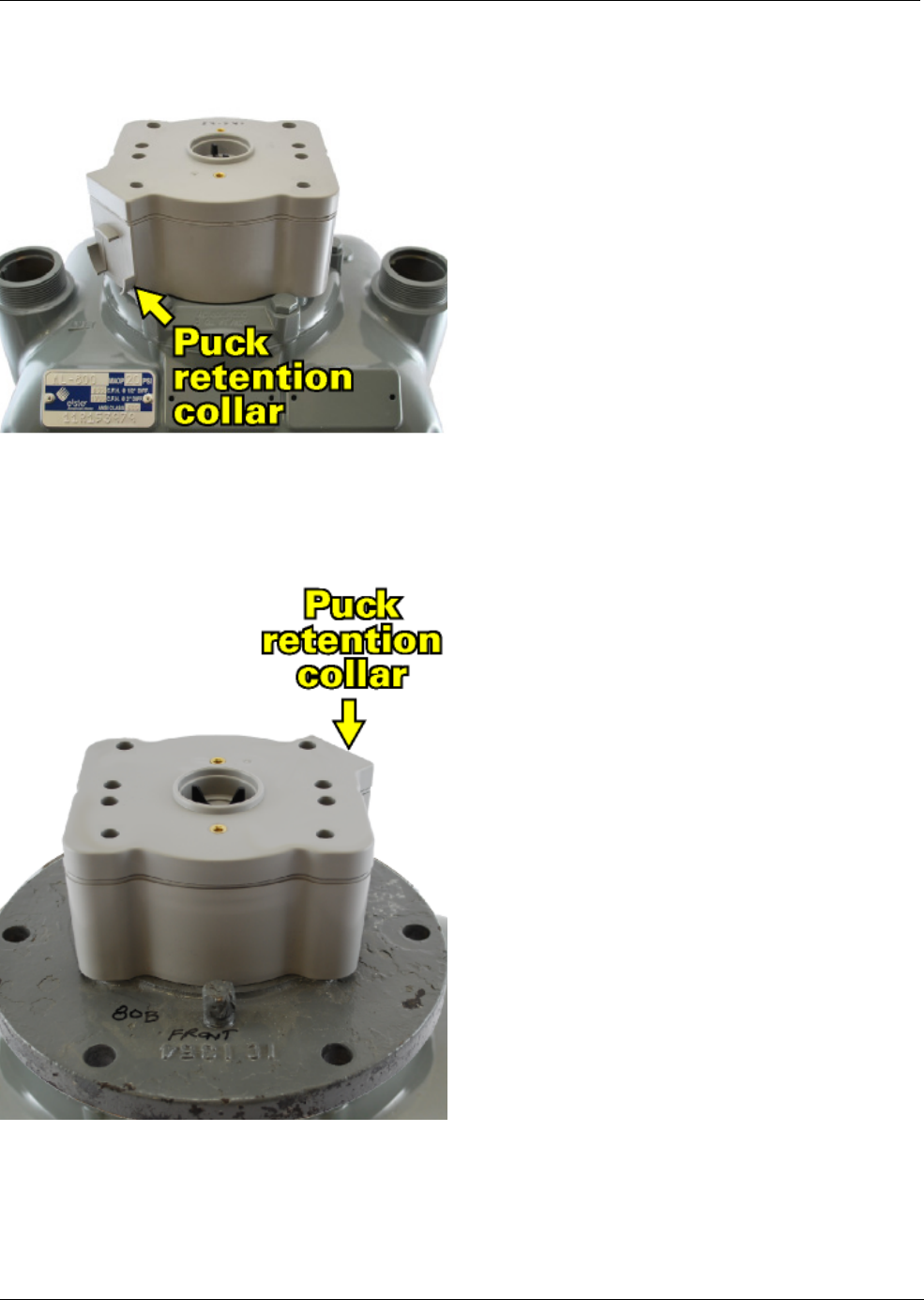
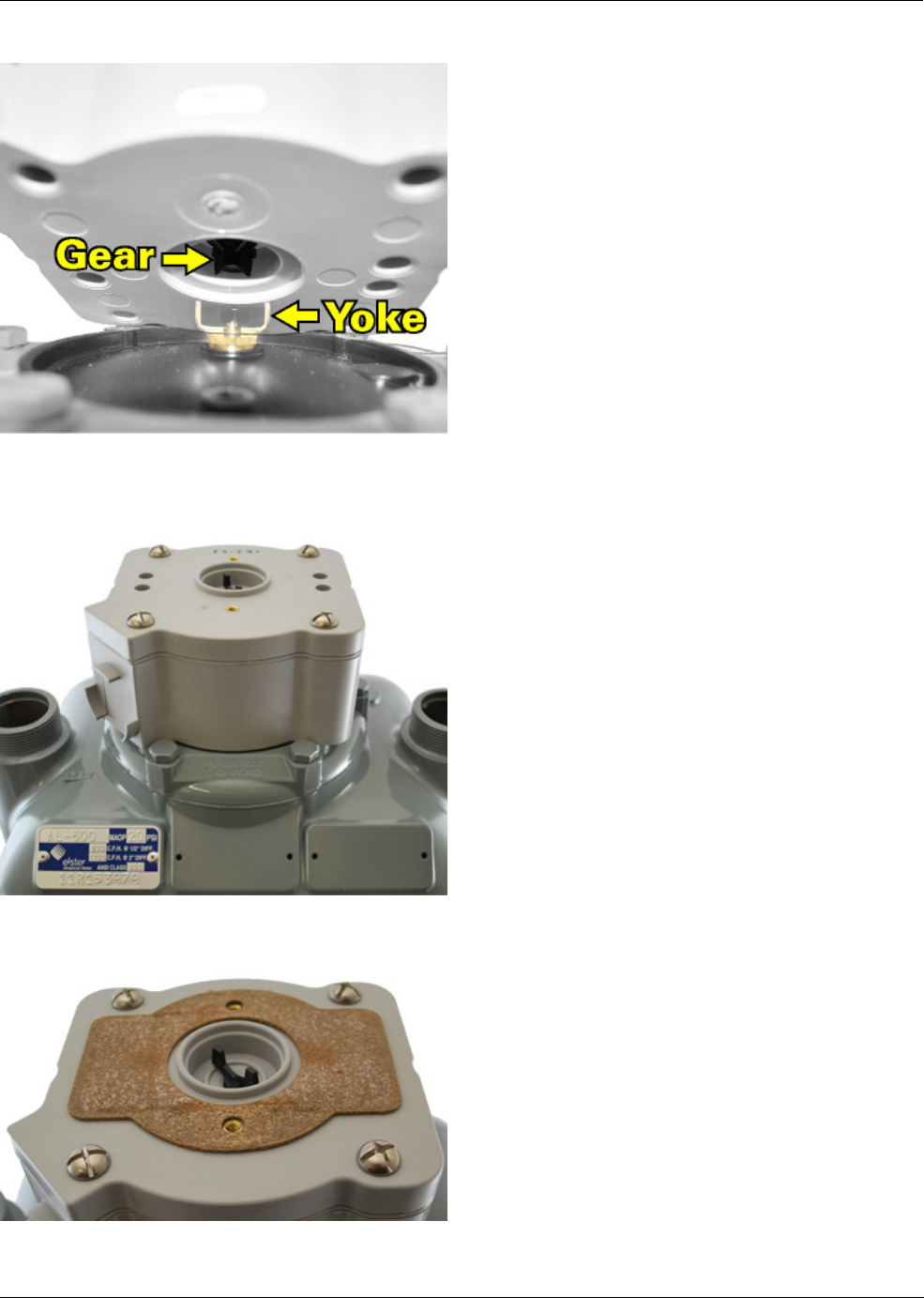
1. Orient the MTU so that the puck retention collar faces the front, left corner of the meter.
NOTE: On some older meters, like the 60B and 80B, the index and MTU are installed 180° so that the
puck retention collar faces the right rear corner of the meter as shown below.
6
Elster / AMCO Gas Meter MTU Installation Instructions
2. Align the gear on the bottom of the MTU with the yoke on the meter.
3. Secure the MTU to the meter using the four #18-18 X 3 1/8" screws. Tighten screws to 12-13 inch-
pounds.
4. Install the gasket on top of the MTU.
Mount Index to MTU
7
Elster / AMCO Gas Meter MTU Installation Instructions
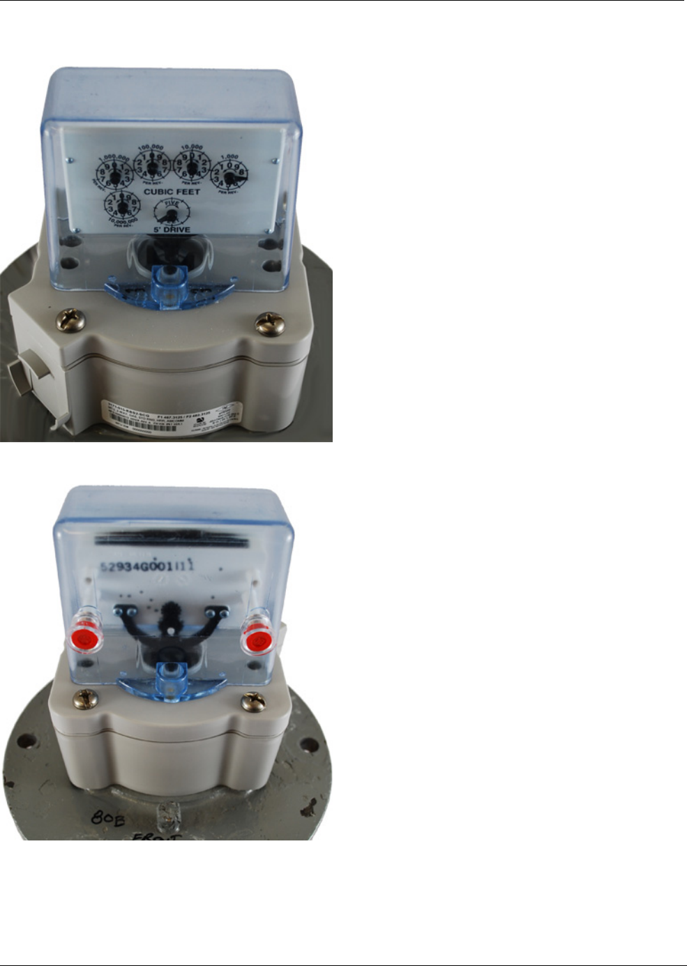
1. Orient the index so that the dials face towards the puck retention collar. On most meters, the dials
should face towards the front of the meter.
NOTE: On some older meters, like the 60B and 80B, the index and MTU must be installed so that the
dials and puck retention collar face the rear of the meter, as shown.
8
Elster / AMCO Gas Meter MTU Installation Instructions
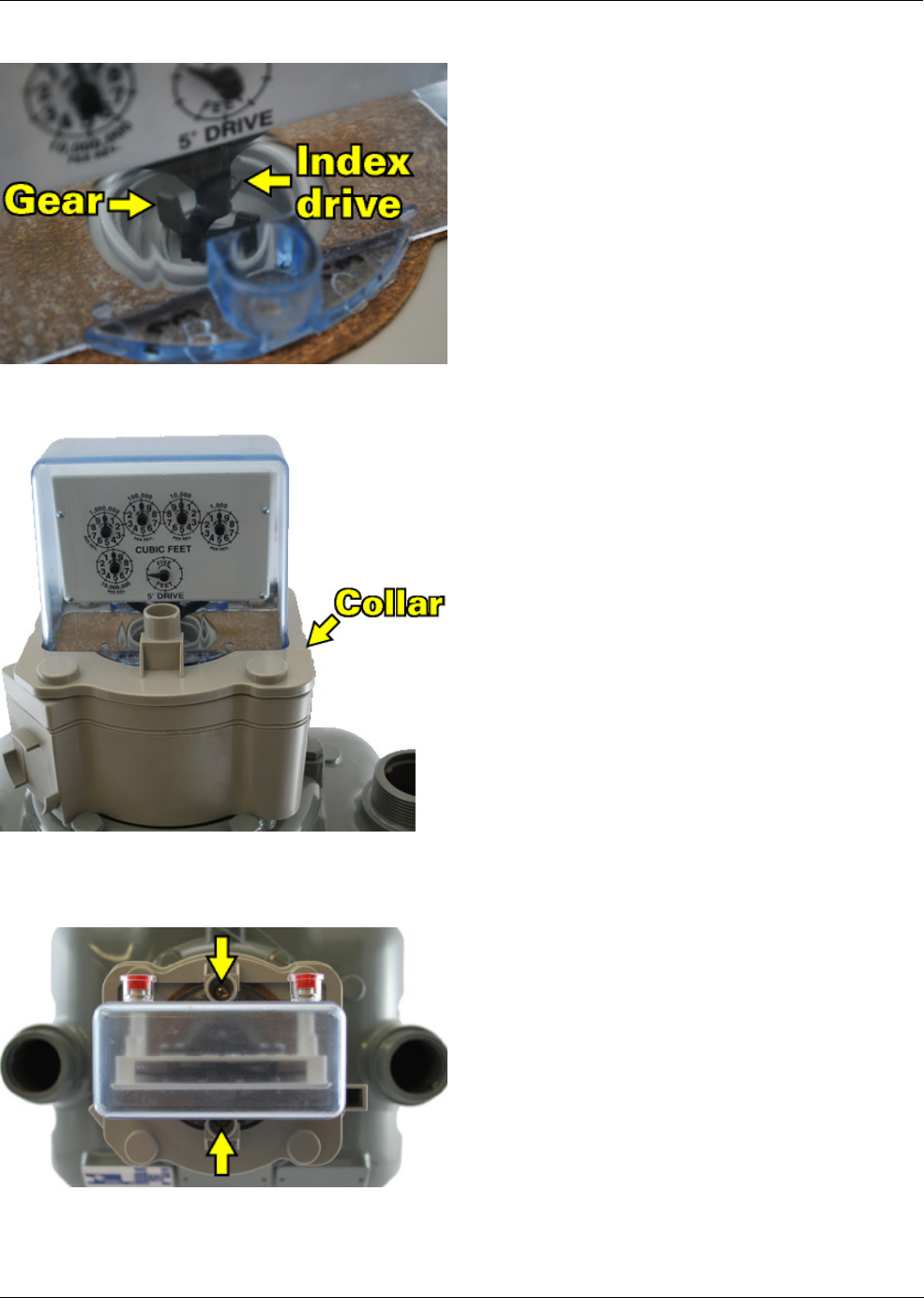
2. Align the index drive with the MTU gear.
3. Position the collar over the index as shown.
4. Secure the index and collar to the MTU using the #10-32 X 1" screws. Tighten both screws to 2-3
inch-pounds.
CAUTION: Excessive torque may damage the MTU enclosure.
9
Elster / AMCO Gas Meter MTU Installation Instructions
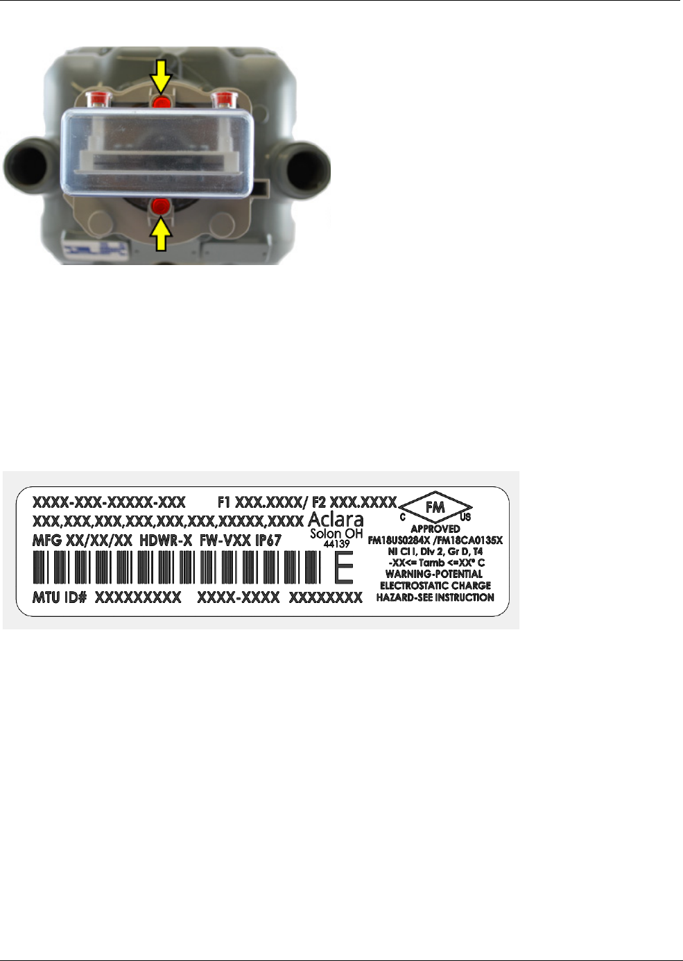
5. Install two anti-tamper plugs in the index cover screw towers as shown.
Putting the Device into Service
Program the MTU using the MTU Programmer software and the Field Programmer.
To take the device out of service, follow the instructions for putting the device into service in reverse
order.
MTU ID Label Examples
N
OTE
Specific Conditions of use in hazardous locations indicated on label.
List of Standards
1. ANSI/ISA 12.12.01
2. CSA 22.2
N
OTE
Training can be provided by Aclara or Aclara can train and certify third party installers. Installers
may be anyone certified by Aclara.

10
Elster / AMCO Gas Meter MTU Installation Instructions