User Manual
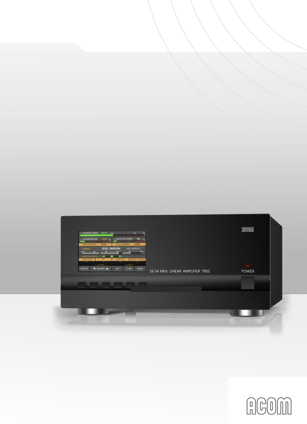
ACOM700S
Outstanding HF Power Products
HF + 6 m LINEAR AMPLIFIER
OPERATING MANUAL
1
TABLE OF CONTENTS
1. GENERAL INFORMATION .........................................................................................................................3
1-1. Inroduction and description .......................................................................................................3
1-2. Owner assistance .....................................................................................................................3
1-3. Equipment supplied and options ...............................................................................................3
1-4. Features .................................................................................................................................... 4
1-5. Safety considerations, explicit denitions .................................................................................4
2. INSTALLATION ...........................................................................................................................................5
2-1. Unpacking and Initial Inspection ...............................................................................................5
2-2. Amplier operating location selection; cooling. ......................................................................... 6
2-3. Connecting the amplier within the shack ................................................................................6
2-4. Installing options and connecting to external devices, computer, etc. ......................................9
3. POWERING AND OPERATION ................................................................................................................10
3-1. Low energy stand-by mode of the power supply ....................................................................10
3-2. Front panel - controls and indication .......................................................................................10
3-3. Initial turning on ...................................................................................................................... 11
3-4. Basic screen ........................................................................................................................... 11
3-5. Control system – buttons and menus .....................................................................................13
3-6. Test transmission ....................................................................................................................13
4. AMPLIFIER OPERATION .........................................................................................................................16
4-1. Change of modes, RX / TX and Operate / Stand-by; option AUTO OPERATE ......................16
4-2. Band change, standard and expanded frequency coverage ..................................................17
4-3. Operation with an external antenna tuner ...............................................................................18
4-4. Automatic protection system ................................................................................................... 18
5. MENUS – SETTINGS AND OPTIONS .....................................................................................................19
5-1. Menu “Measurements in the amplier” – AMP MEASURE .....................................................20
5-2. Menu “Service functions in the amplier” – AMP SERVICE. ..................................................21
5-3. Menu CAT/AUX SETTINGS....................................................................................................21
5-4. Menu “USER PREFERENCES” .............................................................................................23
5-5. FAULTS LOG ..........................................................................................................................24
5-6. RESTORE DEFAULT SETTINGS ........................................................................................... 24
6. REMOTE CONTROL ................................................................................................................................25
6-1. General information ................................................................................................................25
7. MAINTENANCE ........................................................................................................................................ 25
7-1. Periodic maintenance; general checks and cleaning ..............................................................25
7-2. Replacement of fuses .............................................................................................................27
7-3. Using the fault codes (signatures) for diagnostics ..................................................................27
7-4. FIRMWARE UPDATES ...........................................................................................................28
8. SPECIFICATIONS ....................................................................................................................................28
8-1. Parameters .............................................................................................................................28
8-2. Functions ................................................................................................................................29
8-3. Storage and shipment ............................................................................................................. 29
9. DISCLAIMER ............................................................................................................................................30
22
1.
GENERAL INFORMATION
1-1.
Inroduction and description
This
manual
describes
the
installation,
operation,
and
maintenance
of
the
HF+6m
solid-state
linear
power
amplier
ACOM
700S.
ACOM
700S is
a
state-of-the art linear
amplier, covering the
amateur
bands
from
1.8
to
54MHz
with
700W output power
(PEP
or continuous carrier)
with less than 40W of drive. The amplifier operating
information is shown on a multi-functional, high resolution color display. ACOM 700S may by controlled
either by the six front panel buttons or remotely
–
via an
RS232
port.
NOTE
ACOM 700S
is
designed
to
work
with the ACOM 04AT Remote
Automatic
Antenna
Tuner.
The
connection
of
ACOM04AT
will
make
accessible
the
features
that
are
inactive
onthe
amplier
display
when
ACOM
700S operates without
ACOM 04AT. The operation of ACOM 700S with ACOM 04AT
is described in the ACOM 04AT Operation Manual.
1-2.
Owner assistance
If
technical
or
operating
assistance
is
needed,
please
contact
your
local
dealer
rst.
In
the
unlikely
case of you needing further information, you may get in touch with ACOM via:
fax
(+ 359 2 920 96 56),
telephone
(+359
2
9209780),
e-mail
(acom@acom-bg.com,
acom@mail.orbitel.bg)
or
by
post
(blvd.
Nikola Mushanov 151, 1330 Soa, Bulgaria).
Website: www.acom-bg.com.
1-3.
Equipment supplied and options
The amplier is supplied in a single box including:
-
amplier ACOM 700S;
-
power cord;
-
this manual with a CE declaration of compliance;
-
four pieces of spare fuses
1-4.
Features
•
5“ high resolution color display (108x65mm), 800x480
pixels, and
24-bit color.
•
The nal
PA
stage uses
a
rugged
LDMOS transistor -
BLF188XR.
•
Compatible
with
all
transceiver
models
available
on
the
market
-
does
not
need
any
special
signals:
„ground on transmit“
and less than
40W
of RF drive power is sufcient.
•
Broadband input circuit, providing a perfect transceiver load with SWR below
1.2:1
(typically
1.1:1),
without retuning throughout the whole frequency range from
1.8
to
54MHz.
•
The overall operation of ACOM 700S is extremely simplied
:
the screen menus are intuitive
and
easy
to
follow,
no
special
skill
is
required
from
the
operator
when
changing
frequency
bands.
3

44
•
Automatic
control
–
when connected
to a transceiver with CAT capability, the amplier will track
the operating frequency, and will change bands accordingly.
•
Even
if
not
CAT connected,
the amplier monitors the input signal frequency through the built-in
frequency counter and automatically switches bands.
•
Remotely controlled by
RS232
port.
•
Takes
care
of
itself
during
operation
via continuously
working
protection
circuits
in
all
modes.
•
The operator
can
monitor
more
than
10 parameters of the amplier in operation.
•
Easy
maintenance
–
detailed
data
(55
parameters)
about each of the last 28 hard-fault protection
trips is stored in
the
amplier’s
memory.
•
Convenient for expeditions and eld operation due to the extremely compact and lightweight
construction and the built-in switching-mode power supply (SMPS) that operates with extended
mains voltage range of 93-265VAC,
with
no
internal switch
over.
The
consumed
current
is
purely
sinusoidal,
Power
Factor
Corrected
(PFC)
andinrush limited. This makes the operation
from unstable mains and generators easy and troublefree.
•
Perfect electromagnetic compatibility (EMC) with both highly sensitive devices and the powerful
devices
in
the
radio
station
(receivers,
computers,
other
ampliers)
exceeding
the
standard
EMC requirements due to the used PFC and built-in radio-frequency lters.
1-5.
Safety considerations, explicit denitions
The ACOM 700S linear amplier is a Class I apparatus regarding protection against electric shock, i.e.
the third grounding lead of its mains cord (colored yellow with two green stripes) and the grounding stud
on the rear panel, marked GND (Fig. 2-1), must be connected to the grounding system of the shack for
safe operation.
The ACOM 700S amplier is designed to meet international safety standards and complies with the CE
electromagnetic compatibility requirements, as well as the FCC regulations.
This
operating
manual
contains
precautions,
cautions,
and
warnings
that
MUST
BE
CОMPLIED
TO
by the user to ensure safe operation and maintaining of the ACOM 700S amplier in a safe working
condition.
PRECAUTIONS:
The EXPLICIT DEFINITIONS described below apply to this operating manual:
W A R N I N G
notes call attention to a procedure which, if not correctly performed,
could result in personal injury or re hazard by electric shock or lightning.
C A U T I O N
notes call attention to a procedure which, if not correctly performed, could result
in equipment damage, not only in the ACOM 700S amplier.
N O T E
notes call attention to a procedure which, if not correctly performed, could result in
inconvenience.

5
W A R N I N G
HIGH VOLTAGE!
Both the mains
voltage
and the
high DC voltage up to 500V
inside
the ACOM 700S amplifier are LETHAL! For your
safety,
disconnect
the
power
plug
from the
mains and WAIT
AT LEAST
three
minutes
EACH TIME,
BEFORE
removing
the
cover of the amplier.
W A R N I N G
HIGH VOLTAGE!
NEVER ALLOW, ESPECIALLY CHILDREN, to insert
anything
into
holes
in
the
case
-
this
may
cause
ELECTRIC
SHOCK!Never
touch
an
antenna
or
antenna
isolators
duringtransmission
or
tuning - this
may result in an electric shockor
burn.
Never
expose
the
amplier
to
rain,
snow
or
anyliquids.
Avoid
placing
the
amplier
in
excessively
dustyenvironments
or
in
direct
sunlight.
DO
NOT
OBSTRUCTCOOLING ducts or vents.
W A R N I N G
Do not undertake repairs or changes in hardware or rmware
of your ACOM 700S
amplier. Doing so will endanger your
or
others‘
health
or
life,
or
damage
the
amplier
and
the
equipment
connected
to
it.
Such
repairs
or
changes
are
not
covered
by the
warranty
and
may
void
the
warranty.
The
manufacturer is not liable for any such
repairs or changes.
Any
such
repairs
or
changes
are
sole
responsibility
of
the
person or persons engaging
in them.
C A U T I O N
To avoid damage
(not covered by the warranty)
please read
the
INSTALLATION
-
Section
2
of
this
operating
manual
carefully.
If
you
have
any
doubts
or
questions
regarding
the
installation,
operation or safety of the ACOM 700S amplifier, please consult
your dealer
immediately.
2.
INSTALLATION
2-1.
Unpacking and Initial Inspection
C A U T I O N
Before
you
commence
installing the ACOM 700S amplifier,
please
read
this
manual
thoroughly.
Carefully
inspect
the
shipping carton and
its contents as described below for
missing
items
(S.
1-3) or mechanical damages. If anything is missing or
is
damaged
(scratched,
bent,
crushed
or
something
is
rattling
inside
or
moving
freely
when
turning
the
amplier
over,
notify
your dealer immediately!
Delaying this notication
may
infringe
the warranty conditions of the
carrier.

66
N O T E
Keep the original packing for possible future transportation.
Unpack and inspect carefully the contents of the cardboard carton for possible transportation damages.
On the amplier, check-up the chassis, front panel, display, buttons, rear panel connectors, main power
switch and fuses.
2-2. Amplier operating location selection; cooling.
Locate the amplier close to the place where will be used. You will need an easy access to the rear panel
for connecting cables, and of course, to the buttons and screen on the front panel.
The ACOM 700S is forced air cooled. Locate the amplier so that there are no objects or other devices
closer than 10cm (4”). The exhaust air can reach 65ºC (150ºF) and if the surrounding devices are
sensitive to heating from outside or use forced air cooling themselves, increase the distances accordingly.
C A U T I O N
Do not leave free paper, cloth or other light materials around
and under the amplier. They may be drawn in by the cooling
air stream and block the vents. This will lead to overheating and
accelerated material aging, not covered by the warranty.
2-3. Connecting the amplier in the shack
W A R N I N G
Before you connect the amplier to external grounding,
you should advise with a licensed electrician and conrm
such kind of connection is allowed by your national and
local electrical code, safety rules, and regulations in force.
Simultaneous connection to the earth grounding and
protective earth may be inadmissible or may fall under
special requirements in some countries!
W A R N I N G
Never use the gas installation pipes for grounding. This can
cause an EXPLOSION!
W A R N I N G
Do not use the steam-heating or water-supply network pipes
for grounding! You may expose to dangerous voltage not only
yourself but also other people using the same installation.
C A U T I O N
Bear in mind that the grounding installation may have to withstand
emergency currents over 15A with minimal voltage drop on it.
Therefore it may be necessary to improve its conductivity using
heavier leads and lower-resistance grounding path.The grounding
lead should be at least 4mm2 (AWG 11 or SWG 13).
For details and recommendations on the grounding and RF counterpoise system concerning the
electromagnetic compatibility see also S. 3-6(f).
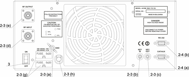
a) GND stud - First connect the grounding stud of the amplier (located on the rear panel and
marked GND – Fig. 2-1) to the grounding system of the shack.
7
b)
KEY-IN jack - amplier input for receive/transmit control from the transceiver.
The transceiver switches the amplier from receive mode into transmit mode (RX/TX) by grounding of
the KEY-IN input.
Run a shielded cable from the output of your transceiver, providing “ground on transmit”, to the KEY-IN
input on the amplier rear panel (RCA PHONO jack – Fig. 2-1). Use a standard RCA PHONO plug for
connection to the amplier.
Transceiver manufacturers give different names to this output, for example: TX-GND, SEND, T/R LINE,
RELAY, and others. In some transceivers “ground on transmit” output should be activated by a menu
or via changing a switch on the rear panel or inside the transceiver. See instructions in your transceiver
manual.
N O T E
Voltage on the KEY-IN jack does not exceed 12V and the
current
is below 6mA.
See also S. 8-2(a).
N O T E
Your amplier will not work if the KEY-IN input is not connected
correctly. If you experience any difculty consult your dealer.
Fig. 2-1 Rear panel connections
c) KEY-OUT jack - transmit-enabling control output from amplier to the transceiver.
The KEY-OUT jack on the rear panel provides an extra control signal from the amplier to the transceiver.
This can be used for improving the receive/transmit (RX/TX) switching safety.
C A U T I O N
KEY-OUT is a low-powered open-collector output, make sure
that the signal voltage coming from the respective transceiver
connection does not exceed 50VDC (open circuit) and the closed-
circuit current is below 20mA.
If your transceiver has a suitable input, that disables transmission unless grounded externally, we
recommend this to be connected to the KEY-OUT jack of the amplier. Use shielded cable terminated
with а standard RCA PHONO plug.
88
The
transceiver
manufacturers
give
different
names
to
this
input,
for
example:
TX-INHIBIT,
MUTE,
LINEAR, and others. Check the manual of your transceiver. Approach your dealer for details. If your
transceiver
has
no
such
input,
do
not
worry
–
ACOM 700S
will
operate
normally
with
KEY-OUT
unconnected.
d)
RF
INPUT
-
Connect
a
coaxial
cable
with
a
PL-259
plug
from
the
transceiver
output
(antenna jack) to the amplier RF INPUT jack.
C A U T I O N
In order to avoid at damage, turn off your transceiver’s internal antenna tuner.
e)
RF OUTPUT - Connect a suitable coaxial cable with a PL-259 plug from the RF OUTPUT
on
the
rear
amplier
panel
to
the
antenna
switch,
tuner
or
antenna
intended
for
the
respective frequency band.
C A U T I O N
If you use
an
amplier for the rst time in your
shack, pay serious
attention
to
the
size
of
coaxial
cable
from
your
amplier
output
to
the
antenna.
The
cable
must
be
capable
of
handling
the
increased power safely, particularly on the 10m and 6m bands.
This
warning
applies
equally
for
the
antenna
switch,
tuner,
and
the whole antenna system,
especially when using
multi-band
trap
antennas.
We recommend using RG213 or better. Consult your local coax cable supplier.
f)
Preparation of the mains outlet for the amplier, requirements for the installation and
the mains voltage.
C A U T I O N
Before
connecting
your
amplier
to
the
power
grid,
be
sure
that the
outlet
is correctly wired and is capable of providing the
required current
i.e.
(up to
10A from 200/240VAC mains and up to
16A from 100/120VAC mains). Also make sure that the grounding
lead is connected properly in the outlet,
intended for the amplier.
If
subsequently
you
connect
the
amplier
to
a
different
outlet,
check
it as well.
It is preferable to use the mains outlet closest to the source. Make sure that the respective fuses and
voltage, of your power mains match the ACOM 700S amplier’s specications (see S. 8-1(g)).
g)
Main fuses.
C A U T I O N
Make sure you check whether the main fuses installed in
your amplier correspond to your local mains nominal voltage
and if necessary replace them as described in Section 7-2!
h)
Power
cord
inlet.
Due
to
different
mains
standards
in
different
countries,
the
ACOM 700S is delivered without a power plug for the mains cable. You dealer might
be able to provide the correct Safety Class I plug. The ground lead of the power cable
is colored yellow with two green stripes. If you have any doubts about the correct way
to connect these wires, consult your dealer.

9
2-4. Installing options and connecting to external devices (transceiver,
computer, etc.)
a) CAT/AUX interface – used for connecting and operating with various transceiver models (see
table 2-1 below and the respective menu in S. 5-3, table 5-1 and Fig. 5-3).
Most of the modern transceivers can be connected by CAT to the ACOM 700S. This will allow the
amplier to track the transceiver frequency without any transmission and change the bands automatically
when in Operate mode. The cable can be supplied optionally, ordered separately or home brewed
according to table 2-1 and the transceiver’s manual.
The CAT connection requires a cable made especially for the ACOM 700S and your transceiver. Wiring
diagrams of such cables can be found at www.acom-bg.com.
Note that some of the connections - to the transceiver’s BCD band data outputs and Band Voltage
outputs do not provide an exact frequency data, but only band data. Those connections cannot be
used when ACOM 700S works together with ACOM 04AT because the tuner needs to know the exact
frequency, not the band.
Table 2-1 shows the signals and the pin out of the CAT/AUX connector - rear panel of the amplier.
Table 2-1
CAT/AUX
interface
PIN
NO. PIN NAME DESCRIPTION SPECIFICATIONS
Rear panel
view
1 RxD Received Data TTL input
2 RxD Received Data RS232 input
3 TxD Transmitted Data RS232 output
4 TxD Transmitted Data TTL output
5 GND Ground 0 Volt
6 BAND voltage Analogue input 0 to +8V
7 Band data 0 Bit 0 TTL input
8 Band data 1 Bit 1 TTL input
9 Band data 2 Bit 2 TTL input
10 Band data 3 Bit 3 TTL input
11 ON RMT Remote Pwr On +4.5 to + 15V / 3mA max
12 Debug mode CPU only Pwr Input +8 to + 15V / 0.4A
13 KEY-IN Tx Request Less than +12V / 6mA
14 KEY-OUT Tx Ready O.C. output, up to
+50V / 20mA
15 GND Ground 0 Volt
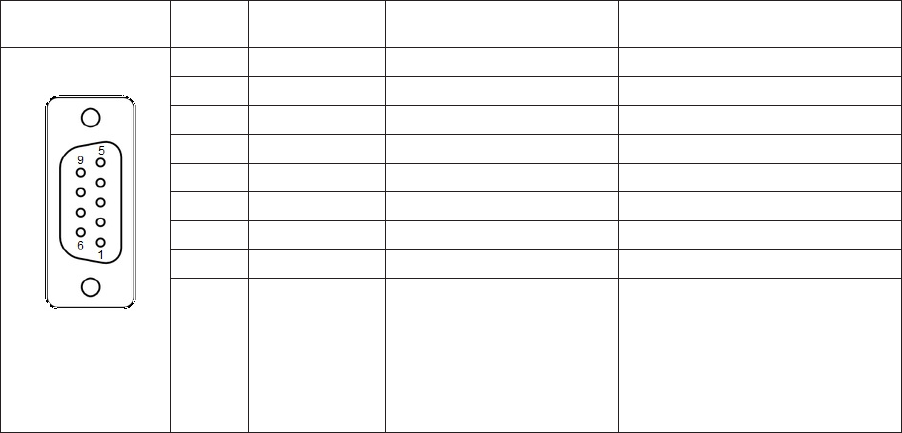
b) RS232 port. Table 2-2 shows signals and pinout of the RS232 port on the amplier’s rear panel.
This connector may remain unused until you decide to control the amplier remotely.
1010
Table 2-2
RS 232
interface
PIN
NO. PIN NAME DESCRIPTION SPECIFICATIONS
Rear panel
view
1 - Not connected -
2 TxD Transmitted Data RS232 level output
3 RxD Received Data RS232 level input
4 - Not connected -
5 GND Ground 0 Volt
6 DSR Remote Power On RS232 level input
7 - Not connected -
8 CTS Remote Power On RS232 level input
9 - Not connected -
3. INITIAL POWER ON AND OPERATION
C A U T I O N
Do not turn the amplier on at least two hours after unpacking it
and installing in its nal operating position. Pay special attention
whenever the amplier is moved from a very cold place to a very
warm one because condensation may develop on the inside
resulting in damage to the high voltage circuits of the amplier.
Under these circumstances, do not turn the amplier on for at least
4 hours. A similar effect could occur following a rapid warming of
the room, such as winter usage of a powerful electric heater.
After following all instructions in Section 2 INSTALLATION, check whether the rear panel mains switch
is turned off. Then plug the amplier in the mains outlet.
3-1. Low energy standby mode of the power supply
Now you can turn on the mains switch on the rear panel. This will activate only the low-energy stand-by
mode of the amplier power supply and will light up the red LED above POWER button, while the main
power supply is still off and the display is dark.
3-2. Front panel - controls and readouts
a) POWER button. When the rear panel mains switch is turned on, push and hold 1-2 seconds to
start the amplier up. When the amplier is turned on, push to turn it off (back to standby mode).
b) LED indicator above the POWER button. When lit red and the screen is dark, the amplier is in
standby mode and may be turned on by pushing the POWER button.