AcoustMax MNREMIX REMIX User Manual Remix speaker UI
ACOUSTMAX INTERNATIONAL CO., LTD REMIX Remix speaker UI
Users manual
User Interface Specificaon
Page 1 o 9
User Interface Specification
for MONSTER Remix SPEAKER
A. Change History:
No. Version Change Summary Owner Date of Changes
1
2
3
4
B. Introduction
1) Purpose
This document defines the user interface requirement of MONSTER Remix Speaker, The purpose of this document is to guide the development
team to implement the user interface software.
2) Scope
This document covers the user scenarios, UI control flows and the display contents of the product.
Part Descriptions
BASS TREBLE
LIGHTING
MODEL
HORN
HEADPHONES
HEADPHONES
MODE
PARTY FX DJ FX
FX LEVER
User Interface Specificaon
Page 2 o 9
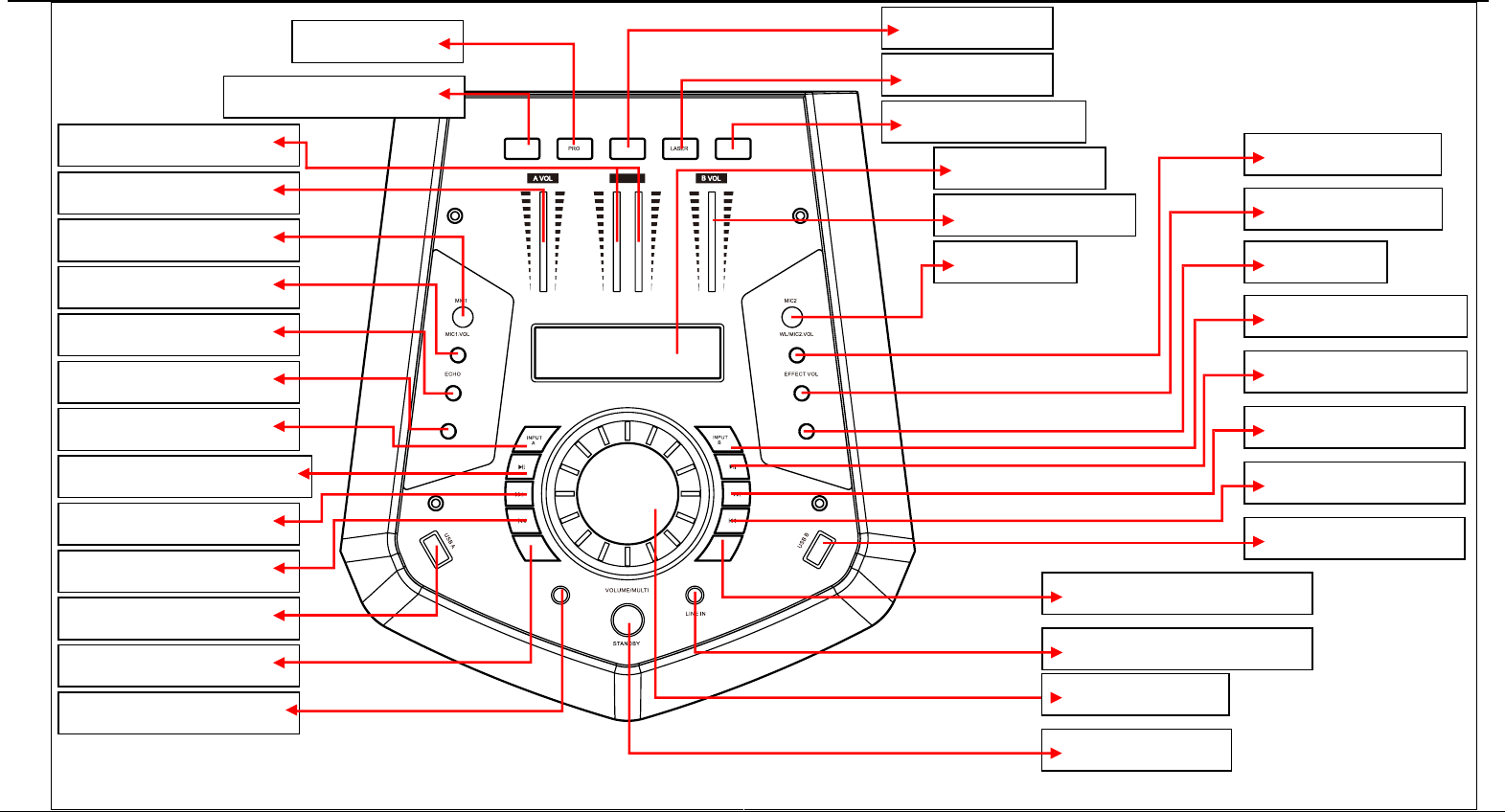
1. PARTY EFFECT button
2. PRO button 3. HORN button
4. LASER button
5. DJ EFFECT button
6. LED DISPLAY
7. INPUT B VOLUME
8. MIC2 jack
9. WL/MIC2 VOLUME
10. EFFECT VOLUME
12. TREBLE
11. INPUT B MODE button
13. INPUT B PLAY/PAUSE
14. INPUT B NEXT button
16. INPUT B PREV button
15. USB B input jack
17. HEADPHONES MODE button
18. LlNE IN AUDIO INPUT JACK
20. VOLUME/MULTI
19. STANDBY button
33. EFFECT LEVER
32. INPUT A VOLUM
31. MICROPHONE 1 jack
30. MIC1 VOLUME
29. ECHO
27. BASS
28. INPUT A MODE button
26. INPUT A PLAY/PAUSE button
25. INPUT A NEXT button
23. INPUT A PREV button
24. USB A input jack
22. LIGHTING MODEL button
21. HEADPHONES INPUT JACK
FRONT PANEL
29.0 mm
User Interface Specificaon
Page 3 o 9
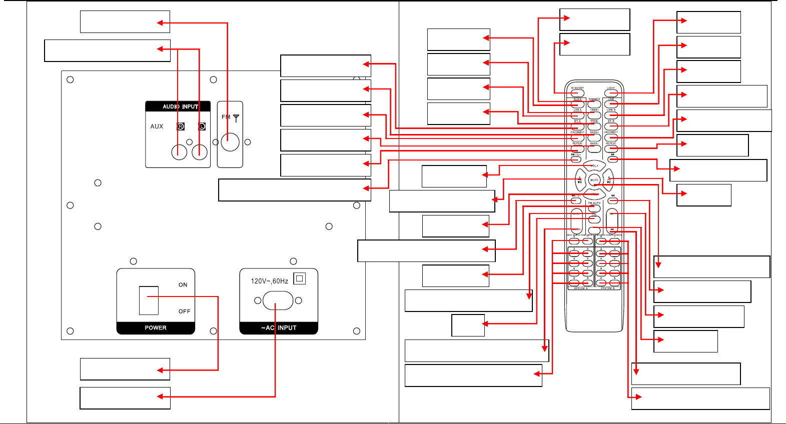
b. AUX AUDIO INPUT JACK
a. FM ANTENNA
d. AC INPUT
c. POWER
PRESET
3. AUX A
4. TREBLE+
5. USB A
7. BLUETOOTH A
9. DISCONNECT A
11. REPEAT A
13. VOLUME+
17. FM.AUTO
6. TREBLE-
8. BASS+
10. BASS-
12. INPUT B F.WARD/FM.TUNING+
14. INPUT A PLAY/PAUSE
20. INPUT A PREVIOUS/CHANNEL-
21. INPUT A NUMBER BUTTON
35. LIGHT
34. LINE IN
33. USB B
31. DISCONNECT B
29. INPUT B F.WARD
27. INPUT B PLAY/PAUSE
25. INPUT B NEXT
23. INPUT B PREVIOUS
32. BLUETOOTH B
30. REPAET B
28. MUTE
26. INPUT B B.WARD
24. PRESET
22. INPUT B NUMBER BUTTON
2. DIMMER
1. STANDBY
15. VOLUME-
16. INPUT A B.WARD/FM.TUNING-
19. FM
18. INPUT A NEXT/CHANNEL+
REAR PANEL & REMOTE CONTROL

User Interface Specificaon
FRONT PANEL
1. PARTY EFFECT mode
Press this key to choose different PARTY effect, POWER UP,SIREN,VECTOR,
FIREWORK,RAINING
2. PRO
3. HORN
4. LASER
5. DJ EFFECT mode
Short press this key to choose different DJ effect SCRATCH,REVERB,BEAT
BOX,YEAH 1,BRING IN,YEAH 2,COME ON.
6. LED DISPLAY
Display System parameter information, a half of the left side display the INPUT
A status, another half of left side display the INPUT B status
7. INPUT B VOLUME
This is used to adjust the volume with INPUT B
8. MIC2 jack
9. WL/MIC2 VOLUME
Adjust the volume of the Wireless microphone and microphone2 input
10. EFFECT VOLUME
Adjust the volume of the EFFECT input
11. INPUT B MODE
Press this key to choose different INPUT B mode, LINE,USB B,BT-B
12. TREBLE
13. INPUT B PLAY/PAUSE
Press this key to choose play/pause music with INPUT B
14. INPUT B NEXT
Press this key to choose next music with INPUT B
15. USB B input jack
16. INPUT B PREV
Press this key to choose previous music with USB B
17. PHONES MODE
Press this key to choose different EARPHONES
18. LlNE IN AUDIO INPUT JACK
Connect to LINE IN signal input jack.
19. STANDBY
20. VOLUME/MULTI
Rotate the knob to adjust the main volume , phones volume,treble, bass.
21. EARPHONES INPUT JACK
22. LIGHTING MODEL
23. INPUT A PREV
Press this key to choose previous music with USB A
24. USB A input jack
25. INPUT A NEXT
Press this key to choose next music with INPUT A
26. INPUT A PLAY/PAUSE
Press this key to choose play/pause music with INPUT A
27. BASS
28. INPUT A MODE
Press this key to choose different INPUT A mode,USB A, AUX,BT-A,FM.
29. ECHO
Adjust the ECHO depth of the MIC input.
30. MIC1 VOLUME
Adjust the volume of the MICROPHONE 1 input.
31. MICROPHONE 1 jack
32. INPUT A VOLUME
This is used to adjust the volume with INPUT A
33. EFFECT LEVER
Slide the lever to create a party atmosphere
Page 4 o 9
User Interface Specificaon
REAR PANEL & REMOTE CONTROL
a. FM ANTENNA
AUX AUDIO INPUT JACKb.
Connect to AUX signal input jack.
c. POWER
Press this switch to turn the unit on or off.
d. AC INPUT
AC 120V~,60Hz
1. STANDBY
2. DIMMER
3. AUX A
4. TREBLE+
5. USB A
6. TREBLE-
7. BLUETOOTH A
8. BASS+
9. DISCONNECT A
10. BASS-
11. REPEAT A
12. INPUT B F.WARD /FM.TUNING+
13. VOLUME+
14. INPUT A PLAY/PAUSE
15. VOLUME-
16. INPUT A B.WARD /FM.TUNING-
17. FM.AUTO
18. INPUT A NEXT /CHANNEL+
19. FM
20. INPUT A PREVIOUS /CHANNEL-
21. INPUT A NUMBER BUTTON
22. INPUT B NUMBER BUTTON
23. INPUT B PREVIOUS
24. PRESET
25. INPUT B NEXT
26. INPUT B B.WARD
27. INPUT B PLAY/PAUSE
28. MUTE
29. INPUT B F.WARD
30. REPAET B
31. DISCONNECT B
32. BLUETOOTH B
33. USB B
34. LINE IN
35. LIGHT
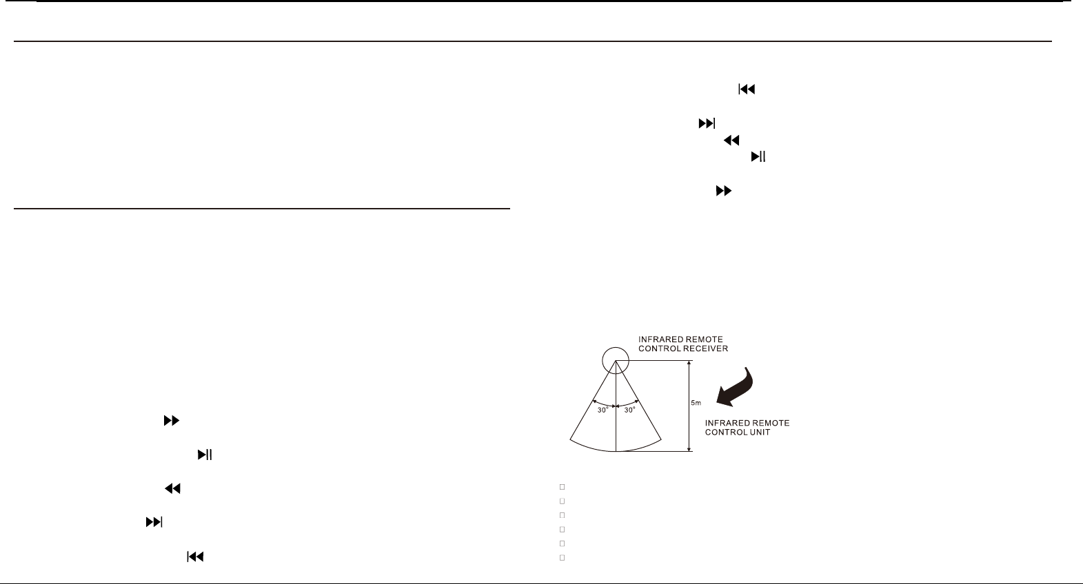
If the remote control with other devices,the operation will be affected.conflicts
Do not simultaneously press buttons on the unit and the remote control.
Avoid using two remote controls at the same time as this wiII cause a malfunction.
Use only UM-4 ``AAA`` size batteries. Do not mix old batteries with new ones.
If the batteries Ieak, clean thoroughly before replacing with new ones.
Do not short two terminals of the batteries. Dispose of old batteries in a suitable place.
REMOTE CONTROL OPERATION:
Page 5 o 9

User Interface Specificaon
NORMAL FUNCTION
1. Be sure to switch off the power and to connect to corresponding input jacks.
2. Turn on the power and wait 3-4 seconds until the speaker functions are connected.
3. Select an audio source by pressing the INPUT A key on the front panel to display AUX A, BT-A, USB A. Press the INPUT B key on the front panel to
display LINE,USB B,BT-B.
4. Adjust the VOLUME/MULTIknob on the front panel or the VOL+/- key on the remote control to adjust the setting of the main volume, . Then turn treble, bass
the left push shot to adjust the volume of INPUT A, turn the right push shot to change the volume of the INPUT B.
5. Press the MENU key on the front panel to display BASS, TREBLE,AUTO, MAIN then adjust the VOLUME knob to change music treble,bass,light mode
and sound effect.
6. PHONES OUTPUT selection. Press the PHONES MODEL button on the front panel to display INPUT A, INPUT B, or INPUT AB. PHONES VOLUME
adjustment. Press the PHONES MODEL button on the front panel to display INPUT A or INPUT B or INPUT AB, then rotate the VOLUME/MULTI knob to
adjust the PHONES VOLUME of INPUT A or INPUT B or INPUT AB
7. Press the LIGHT button on the remote control or press the MENU button on the front panel to display light mode,then press the VOLUME/MULTI knob to
change the OFF,R,G,B,RG,RB,GB,RGB, AUTO,DEMO light mode.
8. Press the MUTE key to mute, press it again to reset.
SOUND EFFECT
1. DJ EFFECT
Press DJ FX on the front panel can select DJ effect, SCRATCH,REVERB,BEAT BOX,YEAH 1,BRING IN,YEAH 2,COME ON.
2. MUSIC EFFECT
Press LASER,HORN,PRO on the front panel to choose music effect.
3. PARTY EFFECT
Press “PARTY FX” on the front panel can select PARTY effect, POWER UP,SIREN,VECTOR,FIREWORK,RAINING. Push the PARTY EFFECT rod,
can get the corresponding PARTY EFFECT, when rod arrive the MAX position, can get the corresponding special PARTY EFFECT, When pull the rod back to
OFF, PARTY EFFECT turn off. The complete process is OFF--->PARTY EFFECT---> PARTYMAX
LIGHT COLOR CONTROL FUNCTION
To control the light mode coming from the speaker panels by "Speaker" menu or "light model" button on remote control
• R = red lights flash
• G = green lights flash
• B = blue lights flash
• RG = red and green lights flash
• RB = red and blue lights flash
Page 6 o 9

User Interface Specificaon
• GB = green and blue lights flash
• RGB = red, green, and blue lights flash
• Auto = the various color combinations cycle through and flash.
• Demo = lights flash and change color as if they were responding to the beat of the music.
TUNER APPLICATIONS
1. Before using the radio functions, you must attach the supplied antenna. Adjust the antenna to obtain optimum reception. Press the INPUT A key on the
front panel(amplifier)or the FM key on the remote control,to select FM function.
2. Press the CH+/CH- key on the remote control to find radio bands that you have previously saved .
3. Press or hold the TU+/TU- key on the remote control to adjust the radio frequency manually.
4. Press the AUTO key on the remote control, the machine will scan radio channels from low-frequency to high-frequency by itself and memorize the
channels one by one.
KARAOKE FUNCTION
1. Please turn off the microphone volume and adjust the volume gradually after inserting the microphone.
2. to change the microphone VOLUME. Adjust the MIC.VOL knob on the front panel
3. A to change the microphone ECHO.djust the ECHO knob on the front panel
Note: Do not touch the top of the microphone when singing in order to avoid howling effect. Adjust the microphone volume gradually to avoid howling effect.
Function of NFC
For the smartphone with NFC (Near Field Communication) function, you can easily perform the pairing operation just by touching the NFC mark on this
unit with your smartphone (you need to turn on the power of this unit and turn on the NFC function of the connecting device beforehand).
1.Press the (power) button to turn on the power of this unit.
2.Perform the pairing operation on the connectong device (for details, referto the owner s manual of the connecting device).
If the connection fails, move the smartphone slowly on the NFC mark. If the smartphone is equipped with a case, remove the case.
What is NFC?
Near Field Communication (NFC) is a standards-based connectivity technology that makes it more convenient to make transactions, exchange digital
content and connect devices.
Using NFC you can transfer information between your phone and other NFC devices, such as phones and other mobile devices, payment devices and
home audio and video devices.
For example, you can share web addresses, contacts, phone numbers, music tracks, videos or photos.
NFC is activated by bringing two NFC devices together. The maximum reading distance is about one centimeter,which helps prevent unauthorized
communications.
Page 7 o 9

User Interface Specificaon
BLUETOOTH PAIR AND CONNECT
• Turn off any Bluetooth devices previously paired (linked) with this unit.
• Turn on the Bluetooth features on your phone or music player.
• Turn on and set this unit to Bluetooth mode. The flashing blue light BT on LED display indicates it is
in pairing mode.
• Set your phone or music player to search for Bluetooth devices.
• Select MONSTER REMIX A or MONSTER REMIX B from search results on your phone or music player.
• Select OK or YES to pair this unit with your phone or music player.
• If protected, enter 0000 for passkey steady blue light indicates successful connection.
• Press the DISCONNECT key on the remote to disconnect the bluetooth.
FUNCTION OF USB READER
USB A interface
This unit has two USB jacks. Press the INPUT A key to select USB A,then you can insert a USB to play music. Press the INPUT B key to select USB B,then
you can insert the another USB to play music.
Important: The USB port is intended only for data transfer only, other devices cannot be used with this USB connection. The use of USB extension cords is
not recommended.
Page 8 o 9

User Interface Specificaon
SPECIFICATION
Frequency Response:
BASS-------------------------------------------------------------------------------------------------------------------------------------------------------------- 20Hz-3KHz
TREBLE----------------------------------------------------------------------------------------------------------------------------------------------------------3KHz-20KHz
Power Source------------------------------------------------------------------------------------------------------------------------------------------------------- 120V~,60Hz
Power Consumption ------------------------------------------------------------------------------------------------------------------------------------------------------150W
ACCESSORIES
Remote control with battery------------------------------------------------------------------------------------------------------------------------------------------------1 pc
Manual -----------------------------------------------------------------------------------------------------------------------------------------------------------1 pcInstruction
FM antenna--------------------------------------------------------------------------------------------------------------------------------------------------------------------1 set
Wireless microphone with battery----------------------------------------------------------------------------------------------------------------------------------------1 pc
Aux in cable--------------------------------------------------------------------------------------------------------------------------------------------------------------------1 set
US Power cord-----------------------------------------------------------------------------------------------------------------------------------------------------------------1 set
Page 9 o 9
The specification presents only as a reference. The value of weight and size are approximation.
Our product is improved ceaselessly and the specification and function may be changed without prior notice
THIS DEVICE COMPLIES WITH PART 15 OF THE FCC RULES. OPERATION IS SUBJECT TO THE FOLLOWING TWO CONDITIONS: (1) THIS DEVICE MAY NOT CAUSE HARMFUL INTERFERENCE, AND (2)
THIS DEVICE MUST ACCEPT ANY INTERFERENCE RECEIVED, INCLUDING INTERFERENCE THAT MAY CAUSE UNDESIRED OPERATION. SHIELDED CABLES MUST BE USED WITH THIS UNIT TO
ENSURE COMPLIANCE WITH THE CLASS B FCC LIMITS
FCC Statement
This equipment has been tested and found to comply with the limits for a Class
B digital device, pursuant to part 15 of the FCC rules. These limits are
designed to provide reasonable protection against harmful interference in a
residential installation. This equipment generates, uses and can radiate radio
frequency energy and, if not installed and used in accordance with the
instructions, may cause harmful interference to radio communications.
However, there is no guarantee that interference will not occur in a particular
installation. If this equipment does cause harmful interference to radio or
television reception, which can be determined by turning the equipment off and
on, the user is encouraged to try to correct the interference by one or more of
the following measures:
-Reorient or relocate the receiving antenna.
-Increase the separation between the equipment and receiver.
-Connect the equipment into an outlet on a circuit different from that to which
the receiver is connected.
-Consult the dealer or an experienced radio/TV technician for help.
To assure continued compliance, any changes or modifications not expressly
approved by the party.
Responsible for compliance could void the user’s authority to operate this
equipment. (Example- use only shielded interface cables when connecting to
computer or peripheral devices).
This equipment complies with Part 15 of the FCC Rules. Operation is subject
to the following two conditions:
(1) This device may not cause harmful interference, and
(2) This device must accept any interference received, including interference
that may cause undesired operation.
FCC Radiation Exposure Statement:
The equipment complies with FCC Radiation exposure limits set forth for
uncontrolled enviroment. This equipment should be installed and operated with
minimum distance 20cm between the radiator and your body.
.