Acroprint Time Recorder 1011 ENTRY CONTROL BADGE READER User Manual Micro computer Electronic Time Clock
Acroprint Time Recorder Company ENTRY CONTROL BADGE READER Micro computer Electronic Time Clock
Contents
- 1. USERS MANUAL 1 OF 4
- 2. USERS MANUAL 2 OF 4
- 3. USERS MANUAL 3 OF 4
- 4. USERS MANUAL 4 OF 4
USERS MANUAL 1 OF 4
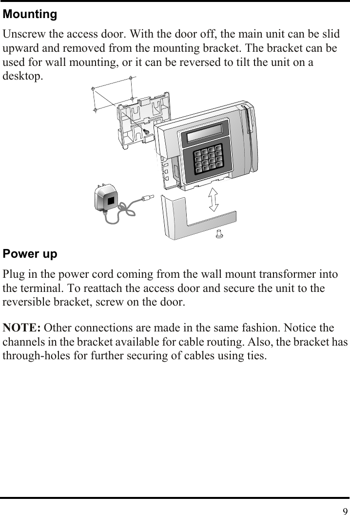
![2. Setup Site requirements The terminal can be installed in any normal office or controlled factory environment. However, do not use the terminal under the following conditions: • extremely high or low temperature [operating temperature range: 0° to 50° C (32° to 122° F)] [storage temperature range: -20° to 60° C (-4° to 140° F)] • extremely high or low humidity [operating humidity range : 10 to 90% RH non-condensing] • areas of high dust concentration • areas with chemical fume concentration • areas with extreme vibration or when placed on an unstable or unleveled surface Unpacking and Inspection Opene the shipping carton and carefully remove the contents. Inspect the terminal and accessories for damage. Report damage or shortages to the company from which the unit was purchased. Complete the registration card with all of the information. (1) Terminal(4) Mounting Screws(1) Power Supply(1) Manual 8](https://usermanual.wiki/Acroprint-Time-Recorder/1011.USERS-MANUAL-1-OF-4/User-Guide-604720-Page-8.png)