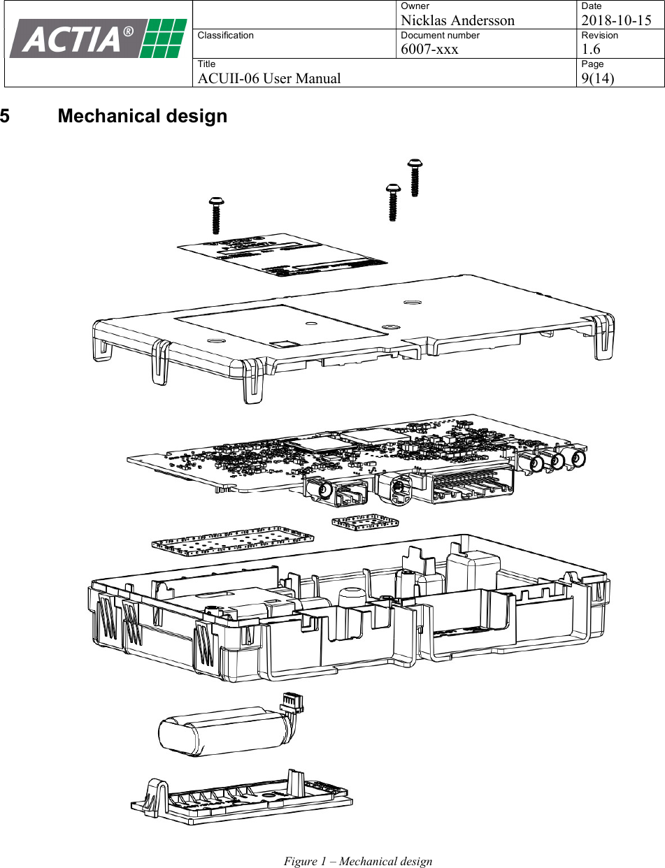
Actia Nordic ACUII-06H2 ACUII-06 User Manual
ACTIA Nordic AB ACUII-06
UserManual.wiki
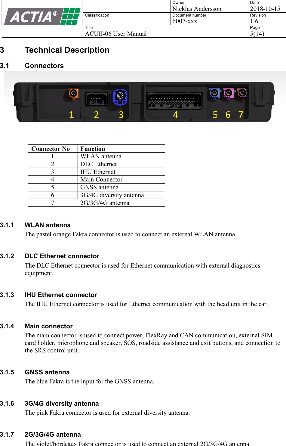
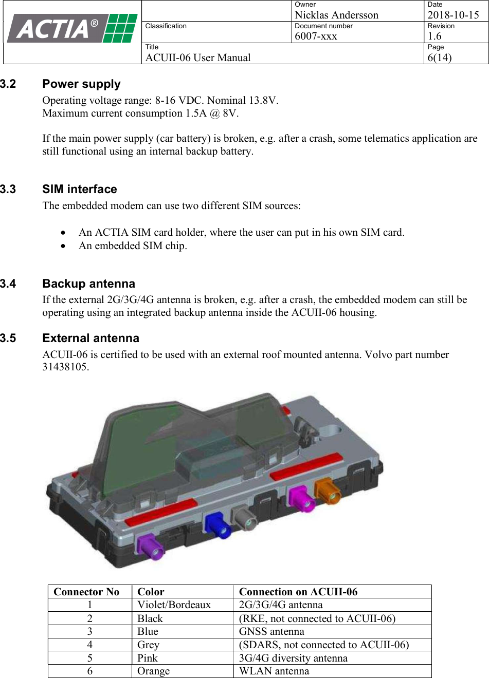
>
Actia Nordic
>
ACUII-06H2 User Manual
>
User Manual
Contents
1.
User Manual
2.
Users Manual
User Manual
Navigation menu
Upload a User Manual
Namespaces
Wiki Guide
HTML
PDF
Info
Views
User Manual
Discussion / Help
Navigation