Action Electronics 9R3HRD00701 7" DIGITAL AUDIO VIDEO PLAYER User Manual HRD00701 IB R4
Action Electronics Co.,Ltd. 7" DIGITAL AUDIO VIDEO PLAYER HRD00701 IB R4
ATI9R3HRD00701_User manual_rev1
AVXMTGHR1D
7“ LCD Monitor
with DVD Player Build
In for Rear Entertaiment
Owner’s Manual / Installation Guide

CONTENTS
1
CONTROLS AND INDICATORS DIAGRAM 9-------------
IMPORTANT NOTICE 2----------------------------------
MATERIAL TO USE IN THIS PACKAGE 3------------------
HEADREST COVER REPLACEMENT 4-------------------
VEHICLE PREPARATION 5
----------------------------
Wireless FM Modulator 6
------------------------------
AVXMTGHR1D WIRING DIAGRAM 7
---------------------
FEATURES 8------------------------------------------
SPECIFICATIONS 8
------------------------------------
REMOTE CONTROL OPERATION 10--------------------
MENU ADJUSTMENT 11--------------------------------
SETTINGS AND ADJUSTMENTS 12----------------------
Selecting Folders and Songs 13
--------------------------
TROUBLESHOOTING 14-------------------------------
Installation of headrest products require careful planning and preparation. Be
extremely careful of seats that have airbags built into them. Keep wiring away from
any air bag wiring (usually identified by yellow connectors and yellow wire jackets).
Damage to air bag wiring can result in personal injury to vehicle occupants. If you
have any questions regarding wire routing or installation in a vehicle, please contact
Audiovox Technical Support at 1-800-225-6074.
When connecting power and ground in a mobile video installation, insure that the
ACC wire is fused at the point where it is connected to the vehicleACC wiring.
Failure to do so can result in damage to the vehicle if a short circuit develops between
the vehicle connection point and the mobile video product.
IMPORTANT NOTICE
An LCD panel and/or video monitor may be installed in a motor vehicle and visible to
the driver if the LCD panel or video monitor is used for vehicle information, system
control, rear or side observation or navigation. If the LCD panel or video monitor is used
for television reception, video or DVD play, the LCD panel or video monitor must be
installed so that these features will only function when the vehicle is in “park” or when
the vehicle’s parking brake is applied.
An LCD panel or video monitor used for television reception, video or DVD play that
operates when the vehicle is in gear or when the parking is not applied must be
installed to the rear of the driver’s seat where it will not be visible, directly or indirectly, to
be operator of the motor vehicle.
Licensed under one or more of the following patents:
Patent NOS. 7,245,274 , 6,899,365 and 6,678,892
2
CAUTION: TO REDUCE THE RISK OF ELECTRIC SHOCK, DO NOT
REMOVE COVER (OR BACK). NO USER-SERVICEABLE PARTS
INSIDE. REFER SERVICING TO QUALIFIED SERVICE PERSONNEL.
RISK OF ELECTRONIC SHOCK
DO NOT OPEN
CAUTION
Any changes or modifications not expressly approved by the party responsible for
compliance could void the user’s authority to operate the equipment.
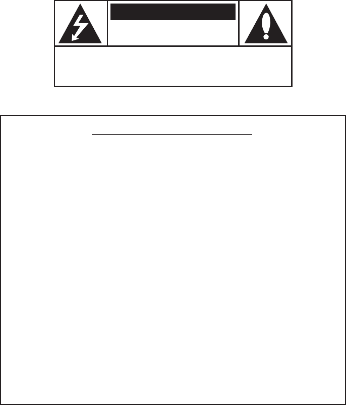
MATERIAL TO USE IN THIS PACKAGE:
Note:
Monitor include headrest cable.
1) System Monitor ( )
Monitor with DVD Player
AVXMTGHR1D AVXMTGHR1D
Note: The AVXMTGHR1D monitor has been designed to
be interchangeable from one headrest to the other. The
headrests will still have the Green and Blue DIN cables on
them and should be connected to their respective
connectors.
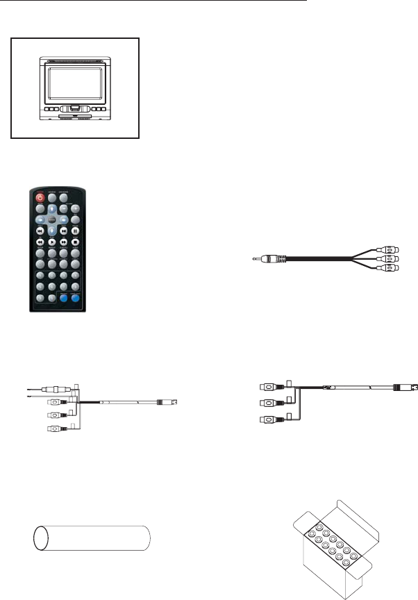
1) Remote Control
(P/N 42-2S-39000G)
-(1pcs)
3) 8PINS (M) DIN CABLE_RED
WITH RCA CABLE
(P/N )-(1pcs)45-2Z-08200G
4) 8PIN (Male) AV OUT to RCA
(P/N )-(1pcs)45-2S-08230G
2) AUX PIGTAIL
(P/N )-(1pcs)112B3227
6)
(P/N )-(1box)
Plastic Pole
83 2S 0002--
5)
(P/N )-(2pcs)
Heat Shrink Tube
31 02 10700G--
3
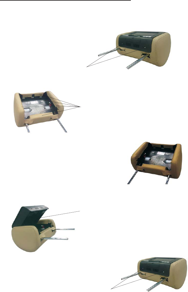
HEADREST COVER REPLACEMENT:
1.Unscrew the two screws,and removed the screen.
Unscrew
Remove
2.Remove the .Hearest cover
3.replace the leather with the matching color cover.
Push
4.connected the cable,lock the monitor's buttons
into position and push it in place to lock.
4
Tighten screws
5.Tighten screws

VEHICLE PREPARATION
1) Read the manuals and get familiar with the electrical requirements and
connections.
2) Prepare the vehicle by removing any interior trim necessary to gain access to the
vehicle's wiring as well as all areas where interconnecting wire harnesses will be
located. (Refer to the Installation Procedure). The mounting method, and the
location will vary from vehicle to vehicle, so this manual will only focus for the
installation of the Monitors in the supplied configuration:
3) Locate an accessory power source (+12VDC present when the ignition key is in
the accessory and run positions. 0VDC should be present when the ignition key
is in the OFF position), and a good ground. Generally, these wires can be
located at the ignition switch or fusebox.
( Ensure that the switched power is fused at the source. Failure to do so
may result in vehicle wiring damage.)
4) Run the wiring harnesses throughout the vehicle as necessary. (Refer to the
Wiring Diagrams on page 7, as well as the wiring instructions for the individual
components and accessory options being installed). Be sure, that all the wiring
is protected from sharp edges and is routed in such a manner that it will not be
pinched, when it is fully installed. Be sure to leave enough slack in the wiring at
each component to allow sufficient working room. Be sure to leave enough
slack in the monitor cables to allow the headrest to move up or down, and the
seat to move backward and forward.
5) Remove all the components from their packaging and then place them in the
vehicle at their respective locations.
6) Install the Headrests:
a. Remove vehicle's original Headrests.
b. Hold the Headrest above the seat and insert the two cables into the headrest
support tube holes. Make sure that the headrest is in the correct position
(Display facing the rear).
c. Route the cables through the seat back and out the bottom of the seat.
d. Place the Headrest support tubes into the support tube holes while pulling
the cables to remove the slack. Be sure to leave enough slack in the monitor
cables to allow the headrest to move up or down.
NOTE:
5

7) Connect all the components together (electrically) and verify proper operation of
all the system functions.
.
8) After verifying the proper operation of the system mount each component.
9) When all the components are mounted, recheck the entire system to be sure it is
functioning correctly. Make sure that no wiring was pinched, or connected
improperly during the final installation.
Wireless FM Modulator
The AVXMTGHR1D is equipped with a built-in wireless FM Modulator*, that allows
you to listen to the DVD audio signal by tuning your vehicle’s radio to the selected
frequency,(,88.5 ). This
feature is accessed by using the FM transmitter buttons on the remote (FMM
ON/OFF, Channel Select).
Whenever the FM Modulator is on, broadcast reception on the vehicles radio will
be poor Switching off the FM Modulator will allow normal radio reception.
MHz,88.9MHz,106.7MHz,107.1MHz,107.5MHz,107.9MHz
*Note: In certain areas where there are a large number of FM radio stations (e.g. large
cities, urban areas), the reception of the FM signal may not be satisfactory, resulting in
static, distorted sound or signal bleed thru from strong local radio stations. This is not a
defect in the product, but the result of a stronger local radio station overpowering the
wireless FM transmitter in your Headrest monifor.
6
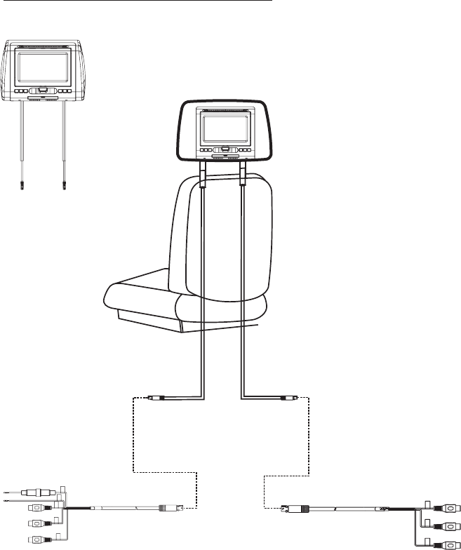
AVXMTGHR1D WIRING DIAGRAM
Headrest Monitor
7
GREEN
RED
(P/N.: 45-2S-08230G)
Note: The headrests will still have the Red and Green DIN cables on them and should
be connected to their respective connectors.
Headrest Monitor
(P/N )45-2Z-08200G
8
FEATURES
• 7” Digital TFT (Thin Film Transistor) Active Matrix LCD
(Liquid Crystal Display) Monitor
• DVD Player
• OSD (On Screen Display) for control of picture quality and
functions
• Three i
•p m
• Screen mode selection (4:3, 16:9)
• Full function remote control
•d
• USB 2.0 port / SD Card Reader
•h
Built-in
Audio / Video Source nputs (DVD/USB/SD CARD, AV
and AUX).
Last osition emory for DVD
Playing DVD, CD and MP3 isc
IR eadphone (optional)
SPECIFICATIONS
Specifications subject to change without notice.
Resolution
Pixels
Operation Temperature
Storage Temperature
Backlit life
Video Display System
Headphone Audio Output
Video Output
Power Source
Dimension (L x W x H)
480x234
336,960
32 ~113º F (0 ~ 45º C)
-4 ~ 149º F (-20 ~ 65º C)
20,000 Hours
NTSC / PAL
0.03W @ 32 ohms
1.0Vp-p @ 75 ohms
10V~16V DC
147mm x 275mm x 200mm
Type TFT Active Martix LCD
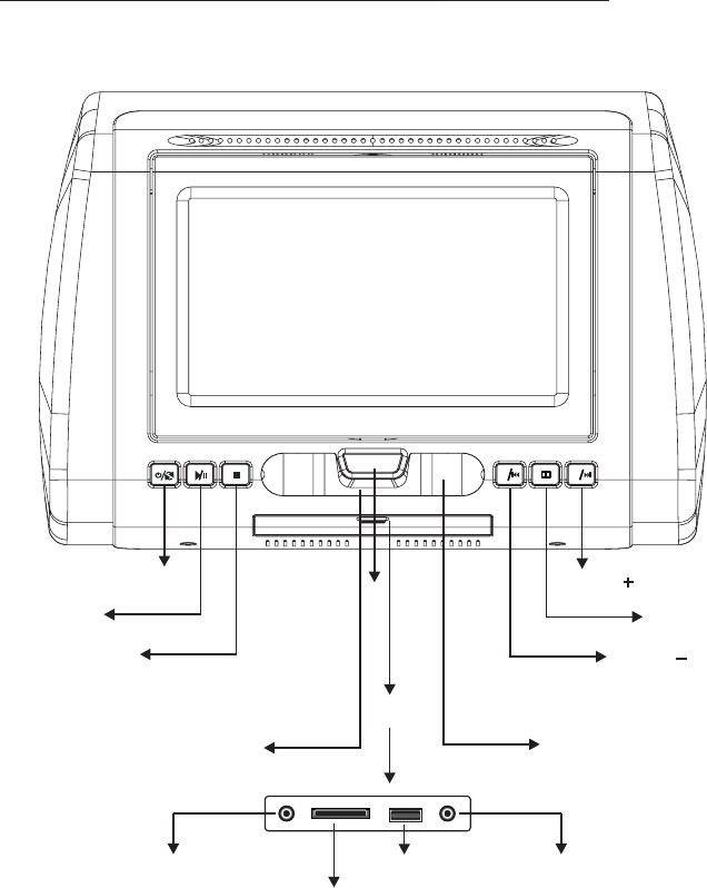
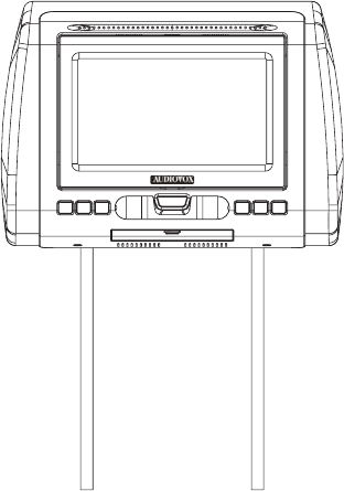
CONTROLS AND INDICATORS DIAGRAM (FRONT VIEW)
9
PUSH
open
-
+
POWER/SOURCE
PLAY/PAUSE
STOP VOLUME PREVIOUS/
MENU
VOLUME /NEXT
PUSH
COVER
IR SENSOR IR HEADPHONE
TRANSMITTER LENS
AUX IN
SD Card Reader
HEADPHONE JACK
USB PORT
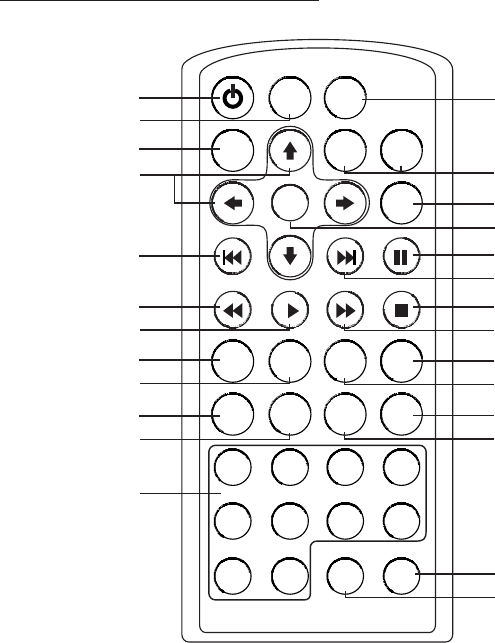
REMOTE CONTROL OPERATION
POWER SOURCE
VOLUME
-+
MUTE
ENTER
PIX
PREV NEXT PAUSE
STOPFFPLAYFR
AUDIOSUBTITLEREPEATSETUP
ZOOM
DVD SOURCE
DISC MENU
DISPLAY
1 2 3 4
5 6 7 8
9 0
FMM ON/OFF CHANNEL SELECT
SYSTEM MENU
1
2
3
4
5
6
7
8
9
10
11
12
13
14
15
16
17
18
19
20
21
22
23
24
25
26
1. POWER
2. SOURCE
3. MUTE
PREVIOUS
7. PLAY
8. SETUP
9. REPEAT
10. ZOOM
11. SYSTEM MENU
12. NUMBERS
13. FMM ON/OFF
4. CURSOR ( )
5.
6. FR
pqtu
14. FMM CHANNEL SELECT
15. DISC MENU
16. DISPLAY
17. SUBTITLE
18. AUDIO
19. FF
20. STOP
21. NEXT
22. PAUSE
23. ENTER
24. PIX ( Picture Select )
25. VOLUME DOWN (-) or UP (+)
26. ZDVD Source
10
11
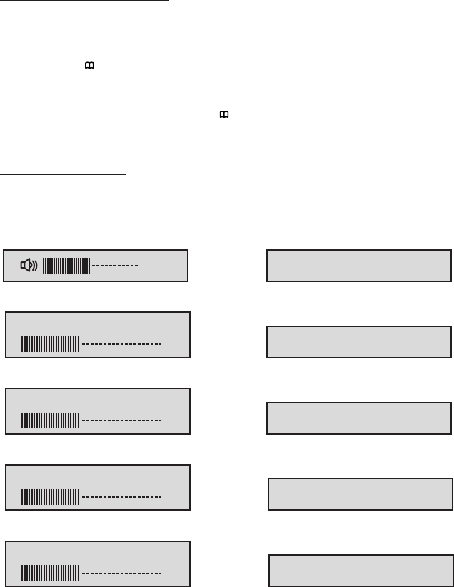
MENU ADJUSTMENT
MENU DISPLAY
The System Menu Contains features and options that let you customize your system to
change the screen mode display and OSD language.
1) Press the “ ” button on unit or the SYSTEM MENU button on the remote control,
the main page of the system menu will appear on screen.
2) Use the buttons to change the setting .
3) To Select to next menu press the “ ” button or the SYSTEM MENU.
“”“”+-
OSD LANGUAGE ENGLISH
16
BRIGHT 16
CONTRAST 16
COLOR 16
TINT 0
SRCEEN MODE 16:9
IRT A
FMM OFF
RESET
12
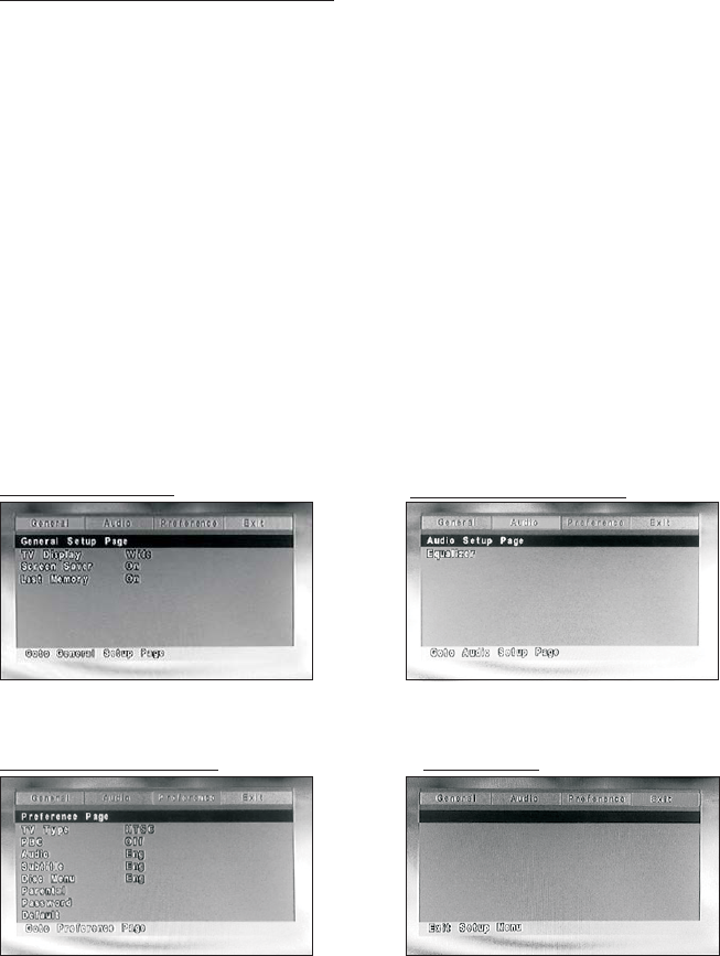
SETTINGS AND ADJUSTMENTS
GENERAL PAGE
The Setup Menu contains features and options that let you customize your DVD
player. For example, you can set a language for the on-screen display or prevent
DVD playback for children.
1. Press the SETUP button on the remote. The Setup Menu appears on the screen as
shown per diagram. There are 5 option on the top part of theSetup Menu. Each
option represents a page.
2. To set the desired option, move the highlight Into the setup area using the cursor
button .
3. After entering the setup area, highlight the desired option using the cursor button
or .
4. Press to open the sub menu that contains the different options available. Press
or to highlight the desired option, and press ENTER to confirm the selection.
5. Repeat steps 3~4 to set the options that reside on the same Setup Page.
6. To change to another Setup page, press to position the highlight back on the icon
side of the setup page. Then, repeat steps 2~5.
Using the Setup Menu
u
p
q
u
pq
t
AUDIO SETUP PAGE
EXIT PAGEPREFERENCE PAGE
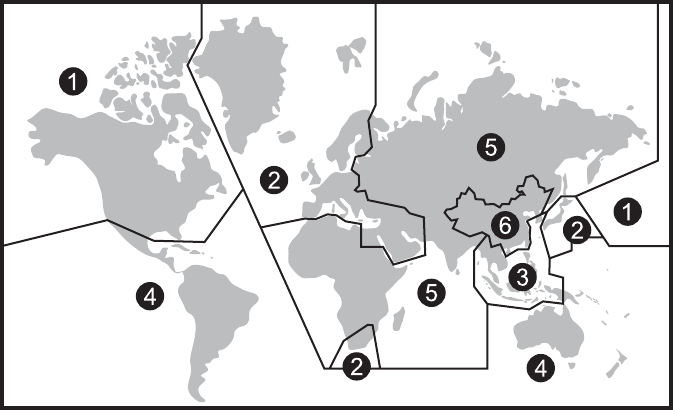
13
Region 1- USA, Canada
Region 2- Japan, Europe, South Africa, Middle East, Greenland
Region 3- S. Korea, Taiwan, Hong Kong, Parts of South East Asia
Region 4- Australia, New Zealand, Latin America (including Mexico)
Region 5- Eastern Europe, Russia, India, Africa
Region 6- China
Selecting Folders and Songs
Selecting a Play Mode
When an MP3 is loaded in the player, the navigation menu appears automatically.
1. Press or to move the highlight to the desired folder and press ENTER to
display the songs in the folder.
2. Press or to move the highlight to the desired folder and press ENTER to
begin playback of the highlighted song.
You can choose what order the songs will play on a disc temporarily. The default
play mode is FOLDER. Press REPEAT consecutively to choose the desired play
mode. The play mode options are :
• Repeat One Repeat the song that is playing.
• Repeat All Repeat the disc that is playing.
• Repeat Off Turn off repeat function.
pq
pq

TROUBLESHOOTING
PROBLEM SOLUTION
IR remote inoperative ?
?
Verify that the batteries in the remote are fresh.
Verify that the remote sensor eye is not obstructed.
Disc won't play ?
?
?
Insert a disc with the label side facing upwards.
Check the type of disc you put into disc tray. This
DVD only plays DVD, audio CD and Mp3.
Both the unit and the disc are coded by region. If the
regional codes don’t match, the disc can’t be played.
Play starts, but then stops
immediately
?
?
The disc is dirty. Clean it.
Condensation has formed. Allow player to dry out.
No sound or distorted
sound
?
?
?
Make sure your DVD is connected properly. Make
sure all cables are securely inserted into the
appropriate jacks.
If you are using the 2-channel IR headphones, make
sure you turn on the IR headphone power, make sure
the correct channel (A-B) is selected.
Make sure the Modulator is ON and the proper
Frequency has been selected. Make sure that unit is
set to M1 when using Single Channel Headphones.
Can’t advance through a
movie
?It can’t advance through the opening credits and
warning information that appear at the beginning of
movies because the disc is programmed to prohibit
that action.
Not allowed at the
moment
?The feature or action cannot be completed at this
time because:
1. The disc’s software restricts it.
2. The disc’s software doesn’t support the feature
(e.g., angles)
3. The feature is not available at the moment.
4. 4 requested a title or chapter number that is out of
range.
Picture is distorted ?
?
The disc might be damaged. Try another disc.
It is normal for some distortion to appear during
forward or reverse scan.
No forward or reverse scan ?
?
Some discs have sections that prohibit rapid
scanning or title and chapter skip.
If you try to skip through the warning information and
credits at the beginning of a movie, you won’t be able
to. This part of the movie is often programmed to
prohibit skipping through it.
14
© 2010 Audiovox Electronic Corp., Hauppauge, Ny11788 XXX-XXXX
15