Action Electronics AVD60001 FM Transmitter User Manual
Action Electronics Co.,Ltd. FM Transmitter
User manual
CUSTOM VEHICLE HEADRESTS
with 7” or 8” Slim Style LED LCD Monitors
with Built-in DVD Player for Rear Seat Entertainment
With FM Transmitter
Installation Guide
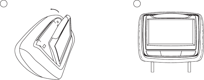
7” Slim Style
LED LCD Monitor
8” Slim Style
LED LCD Monitor
FM Transmtter
IMPORTANT NOTICE
Installation of headrest products require careful planning and preparation. Be
extremely careful of seats that have airbags built into them. Keep wiring away from
any airbag wiring (usually identied by yellow connectors and yellow wire jackets).
Damage to airbag wiring can result in personal injury to vehicle occupants. If
you have any questions regarding wire routing or installation in a vehicle, please
contact VOXX Technical Support at 1-800-225-6074.
When connecting power and ground in a mobile video installation, ensure that the
ACC wire is fused at the point where it is connected to the vehicle ACC wiring.
Failure to do so may result in damage to the vehicle if a short circuit develops
between the vehicle connection point and the mobile video product.
An LCD panel and/or video monitor may be installed in a motor vehicle and visible
to the driver if the LCD panel or video monitor is used for vehicle information,
system control, rear or side observation or navigation. If the LCD panel or video
monitor is used for television reception, video or DVD play, the LCD panel or video
monitor must be installed so that these features will only function when the vehicle
is in “park” or when the vehicle’s parking brake is applied.
An LCD panel or video monitor used for television reception, video or DVD play
that operates when the vehicle is in gear or when the parking brake is not applied
must be installed to the rear of the driver’s seat where it will not be visible, directly
or indirectly, by the operator of the motor vehicle.
Patented, refer to www.voxxintl.com/company/patents.
2
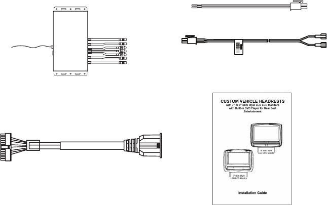
MATERIALS INCLUDED IN THIS PACKAGE:
Installation Package (P/N XXXX) (1pc)
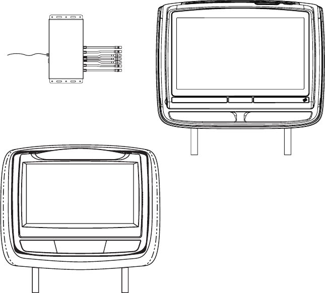
The wireless FM Interface Box automatically determines which headrest
is M1 and which headrest is M2 and sets each headrest to its own
function (IR transmitter channel and IR receiver remote control codes).
The M1 Monitor has Pink/Green DIN connectors and the M2 Monitor has Blue/
Yellow DIN connectors and should be connected to their respective connectors.
3
d) Installation Guide
b) 2 Pin DC Power Cable
(P/N 112-3667) - (1pc)
c) HDMI Cable
(P/N 112-XXXX) - (1pc)
a) Wireless FM Interface Box
(P/N 136-XXXX) - (1pc)
- or -
(P/N 112-4327) - (1pc)

VEHICLE PREPARATION:
1) Read the installation guide and get familiar with the electrical requirements
and connections.
2) Prepare the vehicle by removing any interior trim necessary to gain access to
the vehicle’s wiring as well as all areas where interconnecting wire harnesses
will be located.
a) Monitors: Vehicle-specic Headrest
NOTE:
- The M1 monitor has the pink/green connectors.
- The M2 monitor has the blue/yellow connectors.
b) Wireless FMM Interface Box: Located under either seat where monitors
are located or in the center console.
3) Locate an accessory power source (+12 VDC should be present when the
ignition key is in the accessory and run positions. 0 VDC should be present
when the ignition key is in the OFF position) and a good ground. Generally,
these wires can be located at the ignition switch or fusebox.
NOTE: Ensure that the switched power is fused at the source. Failure to
do so may result in vehicle and wiring damage.
4) Run the power harness from the power source to the wireless FMM Interface
Box. Refer to the Headrest System Wiring Diagram on Page 6. Be sure that
all the wiring is protected from sharp edges and is routed in such a manner
that it will not be pinched when it is fully installed. Be sure to leave enough
slack in the wiring at each component to allow sufcient working room. Be
sure to leave enough slack in the monitor cables to allow the headrest to
move up or down, and the seat to move backward and forward.
NOTE: Do not interfere with airbags or airbag wiring.
5) Install the Headrests:
a) Remove the vehicle’s original headrests.
b) Hold the headrest monitor above the seat and insert the two cables into
the headrest support tube holes. Make sure that the headrest is in the
correct position (Display facing the rear of the vehicle).
c) Route the cables through the seat back and out the bottom of the seat.
d) Place the headrest support tubes into the support tube holes while pulling
the cables to remove the slack. Be sure to leave enough slack in the
monitor cables to allow the headrest monitor to move up or down.
e) Keep monitor cables away from seat tracks to avoid wire damage when
seats are moved.
4
VEHICLE PREPARATION (continued):
6) Connect all the components together (electrically) and verify proper operation
of all the system functions. (Refer to the Headrest System Wiring Diagram on
page 6)
a) Connect the headrest DIN cables to the FMM Interface Box DIN cables
which are color coded. Connect each headrest cable to the correct color
cable on the Wireless FMM Interface Box.
b) Locate an accessory power source (+12 VDC should be present when the
ignition key is in the accessory and run positions. 0 VDC should be present
when the ignition key is in the OFF position) and a good ground. Generally,
these wires can be located at the ignition switch or fusebox..
c) Extend the wireless FM antenna to its full length and orient for best reception.
Do not place it on the Wireless FMM Interface Box or near metal.
NOTE: In certain areas where there are a large number of FM radio stations
(e.g. large cities, urban areas), the reception of the FM signal may
not be satisfactory, resulting in static, distorted sound or signal
bleed thru from strong local radio stations. This is not a defect in the
product, but the result of a stronger local radio station overpowering
the wireless FM transmitter in your headrest system.
If wireless reception is unsatisfactory, an optional wired relay box (Audiovox P/N
FMDIRB) can be installed which will improve audio quality.
7) After verifying the proper operation of the system, mount each component.
8) When all the components are mounted, recheck the entire system to be sure
it is functioning correctly. Make sure that no wiring was pinched or connected
improperly during the nal installation. Refer to the Owner’s Manual for system
operation.
199 CHANNEL WIRELESS FM MODULATOR:
The system is equipped with a 199 channel built-in wireless FM Modulator,
that allows you to listen to the DVD audio signal by tuning your vehicle’s radio to
one of the selected frequencies.
This feature is accessed by using the FM transmitter buttons on the remote control
(FMM ON/OFF). Whenever the FM Modulator is on, broadcast reception on the
vehicle’s radio will be poor. Switching the FM Modulator off will allow normal radio
reception.
5
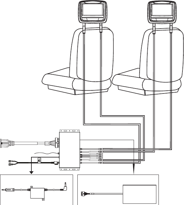
HEADREST SYSTEM WIRING DIAGRAM
Master Monitor Satellite Monitor
OPTIONAL FM DIRECT CONNECTION
HDMI &USB CABLE
FM ANTENNA
INTERFACE
Relay Box for wireless FM Modulator
FMDIRB
AV Output
See the instructions supplied with the FMDIRB for installation.
GAME MODULE
OPTIONAL MVGP1 (GAME PACKAGE)
112-4289
HRM2
GREEN
112-4288
HRM1
PINK
112-4291
HRS2
BLUE
112-4290
HRS1
YELLOW
MVGP1
*
* Use the supplied double sided tape to secure
the game module to the interface box.
FM
BOX
2 PIN DC POWER CABLE
**
DC
IN
** NOTE: Power cable must be fused at the power source to avoid
wiring and vehicle damage in the event of a short circuit.
6
7
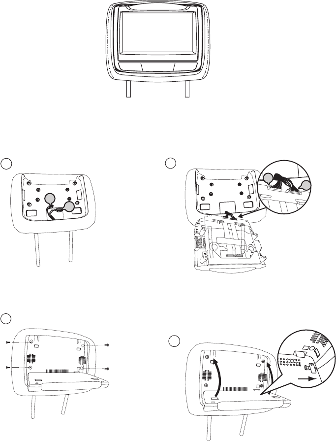
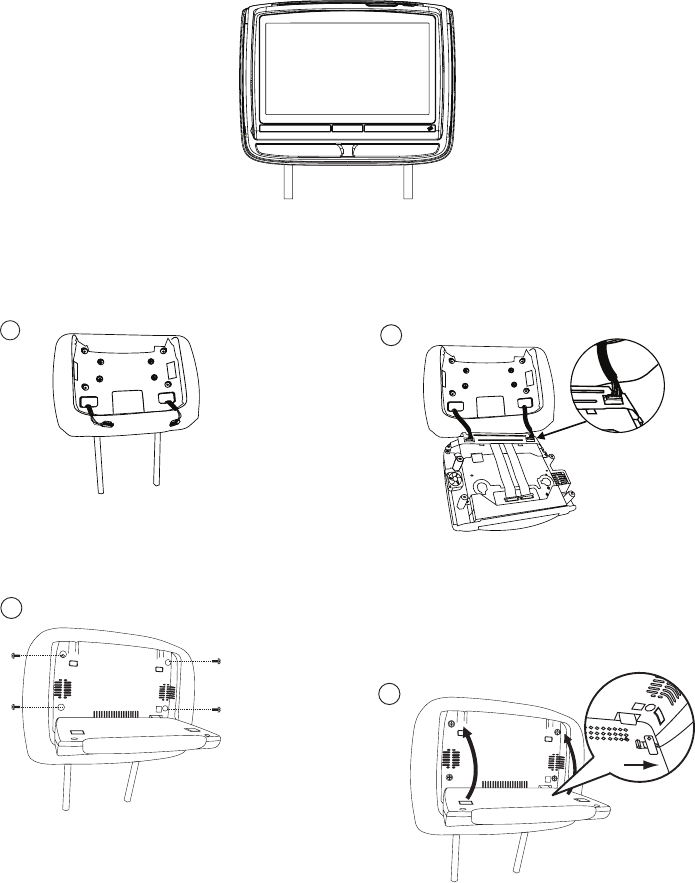
7” ELECTRONICS INSTALLATION/REPLACEMENT GUIDE
2
a)
M1 BLUE headrest connector
b)
Connect
HRM2/HRS2 WHITE cable connector to
M2 WHITE headrest connector
Connect
HRM1/HRS1 BLUE cable connector to
a
b
4
Rotate the screen up and move the locking tab
to the right to lock the monitor into the headrest
tray.
Installation
Install Monitor Unit To Headrest
NOTE: Switch off the ACC power during cable and unit installation. Failure to do
so may damage the unit.
1
a) Master/Satellite monitor headrest
cable (HRM1/HRS1) 8 Pin connector (BLUE)
b) Master/Satellite monitor headrest
cable (HRM2/HRS2) 9 Pin connector (WHITE)
a
b
3
a) Master/Satelite monitor headrest cable
(HRM1/HRS1) 8 Pin connector (BLUE)
b) Master/Satelite monitor headrest cable
(HRM2/HRS2) 9 Pin connector (WHITE)
e) Insert the monitor into the monitor tray.
Make sure that the cables are not trapped
between the monitor and the monitor tray
f) Install Screws (x4)
CAUTION: Do not use a power driver. HAND
TIGHTEN ONLY!
c) Connect HRM1/HRS1 BLUE cable
connector to M1 BLUE headrest connector.
d) Connect HRM2/HRS2 WHITE cable
connector to M2 WHITE headrest connector.
g) Rotate the screen UP and move the locking
tab to the right to lock the monitor into the
headrest tray.
6
Reverse the procedure for removing the electronics.
8
7” ELECTRONICS INSTALLATION/REPLACEMENT GUIDE
(continued)
5
9
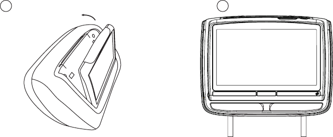
8” ELECTRONICS INSTALLATION/REPLACEMENT GUIDE
2
a)
M1 BLUE headrest connector
b)
Connect
HRM2/HRS2 WHITE cable connector to
M2 WHITE headrest connector
Connect
HRM1/HRS1 BLUE cable connector to
a
b
4
Rotate the screen up and move the locking tab
to the right to lock the monitor into the headrest
tray.
Installation
Install Monitor Unit To Headrest
NOTE: Switch off the ACC power during cable and unit installation. Failure to do
so may damage the unit.
1
a) Master/Satellite monitor headrest
cable (HRM1/HRS1) 8 Pin connector (BLUE)
b) Master/Satellite monitor headrest
cable (HRM2/HRS2) 9 Pin connector (WHITE)
a
b
3
a) Master/Satelite monitor headrest cable
(HRM1/HRS1) 8 Pin connector (BLUE)
b) Master/Satelite monitor headrest cable
(HRM2/HRS2) 9 Pin connector (WHITE)
e) Insert the monitor into the monitor tray.
Make sure that the cables are not trapped
between the monitor and the monitor tray
f) Install Screws (x4)
CAUTION: Do not use a power driver. HAND
TIGHTEN ONLY!
c) Connect HRM1/HRS1 BLUE cable
connector to M1 BLUE headrest connector.
d) Connect HRM2/HRS2 WHITE cable
connector to M2 WHITE headrest connector.
g) Rotate the screen UP and move the locking
tab to the right to lock the monitor into the
headrest tray.
(A) (B)
(B)
(A)
56
Reverse the procedure for removing the electronics.
10
8” ELECTRONICS INSTALLATION/REPLACEMENT GUIDE
(continued)
11
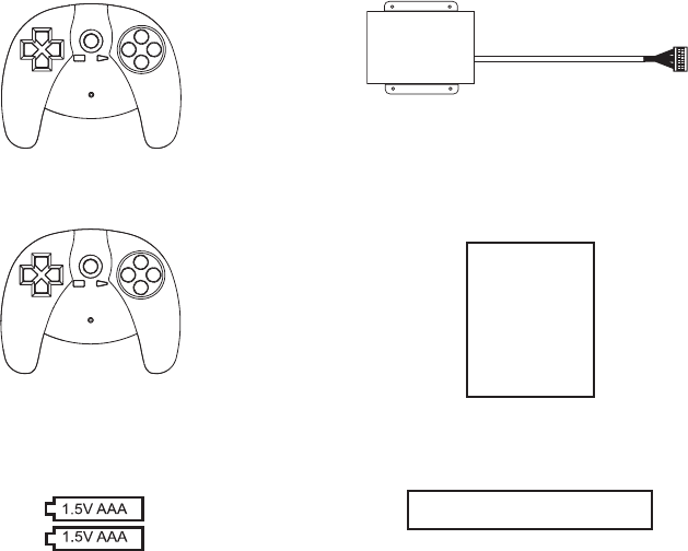
OPTIONAL:
The MVGP1 Game Package is the optional accessory package that allows adding
a wireless game source feature.
MVGP1 Game Module Package (P/N MVGP1)
The Game Module Package contains the following items:
P1
a) Game Controller P1
(P/N 136-5320) - (1pc)
b) Game Controller P2
(P/N 136-5321) - (1pc)
P2
c) Game Module
(P/N 136-5319) - (1pc)
d) Game Module Manual
(P/N 128-9188) - (1pc)
MVGP1 FEATURES:
When the optional Game Pack is installed, either monitor can
be designated as “Player 1”. Selection is based on a “rst come,
rst serve” basis. The second monitor will automatically become
“Player 2.”
Refer to the MVGP1 Instruction Manual for additional installation
instructions.
e) Battery 2 Pack
(P/N 156-2227) - (3pcs)
f) Double Sided Tape
(P/N 138-1507) - (1pc)
TROUBLESHOOTING GUIDE
AUDIO RELATED ISSUES
No audio on wireless headphones while playing a DVD
1. Check that the batteries in wireless headphones are good and that they are
installed properly.
2. Check that the headphones are set to the proper channel: Channel A (1) for the
M1 monitor, Channel B (2) for the M2 monitor.
3. Check that the monitor is not in MUTE mode.
4. Check that the IR transmitter is set to ON.
No audio from Wireless FM modulator
1. Using the remote control, press M1, the TV button and then the DISPLAY
button, check that the OSD indicates that the FM modulator is turned on. If
the FM modulator is OFF, press the FMM power button on the remote control.
2. Is the radio tuned to the same station as the FM modulator?
3. Check to see if there is audio on the RCA output connectors of the FMM
interface box (the FM modulator uses the same audio for the AV output of the
FMM Interface Box).
4. Check the PINK DIN cable for proper connections (audio to and from the M1
monitor travels on the PINK DIN cable).
5. Remove the four screws from the M1 monitor and check the BLUE 8-pin
connector to make sure it is plugged in.
6. If audio is not working, unplug the PINK and YELLOW connectors at the FMM
Interface Box. Plug the YELLOW connector from the M2 monitor into the PINK
connector on the FMM Interface Box. Play a DVD on the M2 monitor, the audio
from the M2 monitor should be heard on the radio.
If audio is heard on the radio most likely there is a problem with the PINK DIN
cable.
If no audio is heard on the radio most likely there is a problem with the GREEN
cable. The GREEN cable controls the FM Modulator.
TROUBLESHOOTING GUIDE (CONTINUED)
No audio on the M2 monitor when playing a DVD on the M1 monitor.
1. Check to see if there is audio on the RCA output connectors of the FMM
interface box (the FM modulator uses the same audio for the AV output of the
FMM Interface Box).
2. If there is audio on the FM Modulator or the RCA output connectors, check the
YELLOW DIN cable for proper connections (audio to and from the M2 monitor
travels on the YELLOW DIN cable).
3. Remove the four screws from the M2 monitor and check the BLUE 8-pin
connector to make sure it is plugged in.
Note: On headrest monitors that have an AUX input on the front, use an RCA
cable to connect from the AV Out of the FMM interface box to the input on the
headrest monitor to check harness wiring.
VIDEO RELATED ISSUES
No video on M2 monitor while playing a DVD on the M1 monitor.
1. Make sure the M2 monitor is set to M1 mode. Press the M2 button on the
remote control and press the SOURCE button until M1 is displayed on the
screen.
2. Check for video out on the YELLOW RCA at the FMM Interface Box.
3. If there is no video in step 2 (above), check the GREEN DIN connector at the
FMM Interface Box and the WHITE connector on the back of the M1 monitor
for proper connections.
4. If steps 2 and 3 check out OK, check the YELLOW DIN connector at the FMM
Interface Box and the BLUE connector on the back of the M2 monitor.
Note: On headrest monitors that have an AUX input on the front, use an RCA
cable to connect from the AV Out of the FMM interface box to the input on the
headrest monitor to check harness wiring.
TROUBLESHOOTING GUIDE (CONTINUED)
IR Remote Control
Remote control does not work on either monitor.
1. Check that the battery is good.
2. Check that the battery is installed properly.
3. To control the M1 monitor, make sure M1 is pressed and the DVD button is
pressed for DVD controls. For system controls, press the M1 button and the
TV button.
4. Test the remote control with a cell phone. Turn on the cell phone camera.
Press and hold a button on the remote control while pointing the remote control
at the cell phone’s camera. If the remote control is working, a blue ickering
light will appear on the screen.
5. Unplug the BLUE DIN cable from the FMM Interface Box and retest the remote
control on the M1 monitor. If the remote control works, there is a problem with
the M2 monitor. Plug the BLUE DIN cable back into the FMM Interface Box.
6. To control the M2 monitor, make sure M2 is pressed and the DVD button is
pressed for DVD controls. For system controls, press the M2 button and the
TV button.
7. Unplug the GREEN DIN cable from the FMM Interface Box and retest the remote
control on the M2 monitor. If the remote control works, there is a problem with
the M1 monitor. Plug the GREEN DIN cable back into the FMM Interface Box.
TROUBLESHOOTING GUIDE (CONTINUED)
M1 DIN cables and M2 DIN cables can be swapped for troubleshooting:
Plug the M2 - Blue connector to M1 - Green connector on the box
Plug the M2 - Yellow connector to M1 - Pink connector on the box
Plug the M1 - Green connector to M2 - Blue connector on the box
Plug the M2 - Pink connector to M2 - Yellow connector on the box
This changes the M1 monitor to the M2 monitor and the M2 monitor to the M1
monitor. The (new) M1 monitor can be used to control the wireless FM modulator.
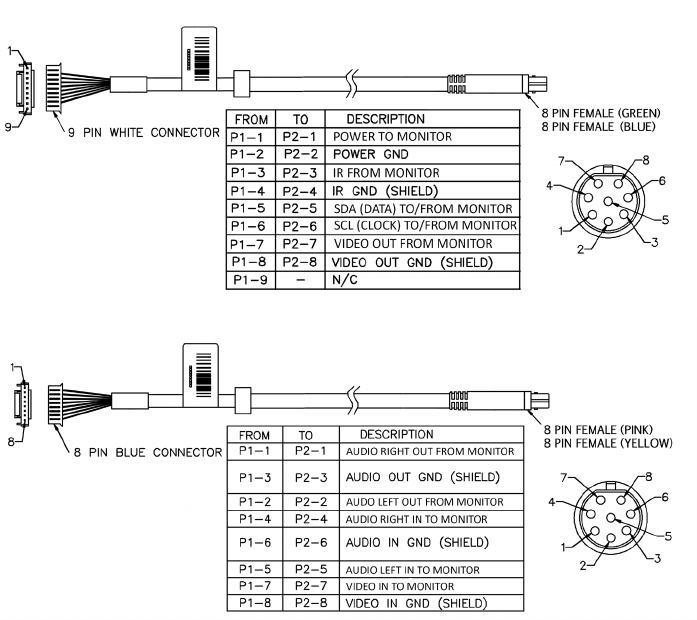
DIN CABLE WIRING FOR M1 and M2 MONITORS

© 2016 VOXX Electronics Corp., Hauppauge, NY 128-XXXX
If you have any questions regarding this product or require technical assistance
please call 1-800-225-6074.
www.voxxelectronics.com
This device complies with part 15 of the FCC Rules. Operation is subject to the following
two conditions: (1) This device may not cause harmful interference, and (2) this device
must accept any interference received, including interference that may cause undesired
operation.
FCC Note
NOTE: This equipment has been tested and found to comply with the limits for a Class B
digital device, pursuant to Part 15 of the FCC Rules. These limits are designed to provide
reasonable protection against harmful interference in a residential installation. This
equipment generates, uses and can radiate radio frequency energy and, if not installed
and used in accordance with the instructions, may cause harmful interference to radio
communications. However, there is no guarantee that interference will not occur in a
particular installation. If this equipment does cause harmful interference to radio or
television reception, which can be determined by turning the equipment off and on, the
user is encouraged to try to correct the interference by one or more of the following
measures:
-- Reorient or relocate the receiving antenna.
-- Increase the separation between the equipment and receiver.
-- Connect the equipment into an outlet on a circuit different from that to which the
receiver is connected.
-- Consult the dealer or an experienced radio/TV technician for help.
Changes or modifications not expressly approved by the party responsible for compliance
could void the user's authority to operate the equipment.