Actiontec Electronics 802AA Wireless Access Point User Manual
Actiontec Electronics Inc Wireless Access Point
Manual

Actiontec Electronics, Inc.
802AA
User Guide

PRELIMINARY
Actiontec Electronics, Inc. COMPANY CONFIDENTIAL
Contents
Preface ...............................................................vii
About this Document..................................................................................vii
Audience ...................................................................................................viii
Additional Resources.................................................................................viii
Regulatory Compliance Information............................................................ix
Radio Frequency Interference Requirements..........................................ix
FCC Warning.........................................................................................ix
RF Exposure Requirements.....................................................................x
1. Introduction..................................................................1-1
Package Contents.......................................................................................1-1
System Requirements.................................................................................1-2
2. Access Point Physical Description...............................1-1
Top Panel...................................................................................................1-1
Rear Panel..................................................................................................1-3
1. AP Web Server.......................................................... A-2-2
Accessing the AP Web Server.................................................................A-2-2
Configuration Windows.........................................................................A-2-4
Working With Configuration Windows...........................................A-2-4
General Configuration Window.............................................................A-2-5

PRELIMINARY
Actiontec Electronics, Inc. COMPANY CONFIDENTIAL
General Advanced Configuration Window............................................A-2-8
Shared Key Configuration......................................................................A-2-8
Per Station Privacy Configuration Window..........................................A-2-10
Script Configuration Window..............................................................A-2-12
Firmware Update Configuration Windows..........................................A-2-14
Statistics Windows...............................................................................A-2-15
AP Statistics...................................................................................A-2-16
Station Statistics.............................................................................A-2-18

PRELIMINARY
Actiontec Electronics, Inc. COMPANY CONFIDENTIAL

PRELIMINARY
Actiontec Electronics, Inc. COMPANY CONFIDENTIAL
Preface
The intent of this document is to familiarize you with the Actiontec Access Point
(AP) Reference Design, its physical characteristics, setup, configuration, and
usage. AP hardware developers should refer to the AP Reference Design Functional
Specification, AP Hardware Design Guide, AP Reference Design Board Layouts, AP
Reference Design Schematics, and AP Reference Design Bill of Materials. AP
software developers should refer to the AP Programmer’s Guide. Both the AR5110
Data Sheet and the AR5210 Data Sheet will provide valuable AR5000 chipset
reference for both hardware and software developers.
After reading this user’s guide, you should be able to install, configure, control,
and maintain the Actiontec AP Reference Design provided as part of an Actiontec
Evaluation or Developer’s Kit.
a. About this Document
This document consists of the following chapters and appendixes:
Chapter 1 Introduction—Describes the Access Point package
contents and system requirements.
Chapter Error!
Reference
source not
found.
2. Access Point Physical Description—Provides a
physical description of the Access Point.
Chapter 2 AP Network Attachment and Configuration—
Describes the Access Point network connections
and initial software configuration.
Appendix A AP Web Server—Describes the use of the web
server to configure the Access Point.

PRELIMINARY
Actiontec Electronics, Inc. COMPANY CONFIDENTIAL
b. Audience
The intended audience for this user’s guide is evaluators and developers of AP
products. The reader is assumed to have conceptual and practical knowledge
about AP concepts, features, and functions. This guide relies on the reader’s
familiarity with APs in general, while discussing the specific characteristics of the
Actiontec AP Reference Design.
c. Additional Resources
Actiontec Reference Design hardware, software, and documentation contain
proprietary information of Actiontec Electronics, Inc., and are provided under a
license agreement containing restrictions on use and disclosure, and are also
protected by copyright law. Reverse engineering of this hardware, software, or
documentation is prohibited.
If you are working with an Actiontec Developers Kit, the following
resources should be referenced regarding topics that are not addressed in this
document:
1. AR5110 Radio-on-a-Chip for 5-GHz Wireless LANs data sheet
2. AR5210 MAC/Baseband Processor for IEEE 802.11a 5-GHz Wireless LAN
data sheet
3. AP Reference Design Functional Specification
4. AP Hardware Design Guide
5. AP Reference Design Bill of Materials
6. AP Reference Design Board Layouts
7. AP Reference Design Schematics
8. CLI Quick Reference
9. AP Programmer’s Guide
10. STA User’s Guide

PRELIMINARY
Actiontec Electronics, Inc. COMPANY CONFIDENTIAL
If you are using an Actiontec Evaluation Kit, you may receive a subset of these
documents.
d. Regulatory Compliance Information
This section contains Regulatory Compliance Information for the AP.
i. Radio Frequency Interference Requirements
This device is restricted to indoor use due to its operation in the 5.15 to 5.25 GHz
frequency range. FCC regulations require this product to be used indoors to
reduce the potential for harmful interference.
High power radars are allocated as primary users of the 5.25 to 5.35 GHz and 5.65
to 5.85 GHz bands. These radar stations can cause interference with and/or
damage to this device.
ii. FCC Warning
This equipment has been tested and found to comply with the limits for a Class B
digital device, pursuant to Part 15 of the FCC Rules., as well as ICES 003 B/ NMB
003 B. Operation is subject to the following two conditions: (1) this device may
not cause harmful interference, and (2) this device must accept any interference
received, including interference that may cause undesirable operation.
If this equipment does cause harmful interference to radio or television reception,
which can be determined by turning the equipment off and on, the user is
encouraged to try to correct the interference by one or more of the following
measures:
11. Reorient or relocate the radio/TV receiving antenna.
12. Increase the separation between the equipment and the radio/TV receiver.
13. Connect the equipment into an outlet on a circuit different from that which
the radio/TV receiver is connected.
14. Consult the dealer or an experienced radio/TV technician for help.
Modifications made to the product, unless expressly approved by Actiontec
Electronics, Inc., could void the user’s authority to operate the equipment.

PRELIMINARY
Actiontec Electronics, Inc. COMPANY CONFIDENTIAL
iii. RF Exposure Requirements
While this device is in operation, a separation distance of at least 20 centimeters
must be maintained between the radiating antenna and the body of all persons
exposed to the transmitter in order to meet the FCC RF exposure guidelines..
Installers and end-users must follow the installation instructions provided in this
user guide.

PRELIMINARY
Actiontec Electronics, Inc. COMPANY CONFIDENTIAL
1.
Introduction
Actiontec AP Reference Design implements an IEEE 802.11a wireless LAN
(WLAN) AP or data-oriented Residential Gateway (RG) on a single PCB.
This Reference Design is intended to provide high-level information to designers
who want to develop a manufacturing-ready product, or architect a new product
based on the Actiontec AR5000 802.11a wireless LAN chipset and the Motorola
MPC8245 Power PC processor.
Detailed information regarding the Actiontec AR5110 and AR5210, Motorola
MPC8245 processor, National Semiconductor DP83185 Ethernet controller, Micron
SDRAM, and Intel Flash memory devices can be found in the appropriate vendor
datasheets or by contacting the appropriate company.
The Actiontec AP Reference Design hardware together with AP Reference Design
software provide an IEEE 802.11a Access Point supporting up to 128 IEEE 802.11a
station associations including the AP itself. Rates of 6 to 54 Mbps are supported in
standard IEEE 802.11a mode, and 12 to 72 Mbps in Actiontec turbo mode. All
transmission rates are supported across the 5.15 to 5.35 GHz spectrum.
e. Package Contents
The Actiontec AP Reference Design is provided in a completely enclosed plastic
housing with two antennas (180° swivel motion), a power supply, and a serial
cable for use in AP software configuration. The AP Reference Design contains a
single 10/100 Ethernet port. Use an RJ-45 cable Ethernet cable (not provided by
Actiontec) to connect the AP to a wired Ethernet LAN. Refer to

PRELIMINARY Chapter 1
Actiontec Electronics, Inc. COMPANY CONFIDENTIAL
AP Network Connections in Chapter 3 for information on connecting the AP to
your LAN.
f. System Requirements
The AP contains a small boot executive that allows the main operating system
software to be downloaded using the Ethernet port over an FTP connection. The
Operating system software can also reside in the Flash memory of the AP, which
allows booting without the need to download the operating system from the host
PC over an FTP connection. A configuration file is created in Flash memory to
store user configurable parameters such as WEP keys. A terminal or PC with an
Ethernet connection is required to perform the initial Operating system software
loading operation, as well as AP configuration. A freeware FTP server (“a-
ftp.exe”) is included on the Actiontec distribution CD in the \utils directory.
Actiontec Electronics provides an FTP site you can use to evaluate the firmware
update capabilities of the AP for test purposes only. By default, Actiontec
Electronicswill set to NULL the default address of the FTP connection. Contact
Actiontec Electronics for the location of the FTP site containing test firmware.
Use the updateparam command to enter parameters for your image and FTP site.
Refer to the AP Programmer’s Guide for information on the updateparam
command.
WARNING: You must confirm that your End User License Agreement (EULA)
covers upgrades to the firmware. The Reference Design upgrade code permits
direct upgrades of the AP from the configuration screen. As a precaution, you
should also use the EULA as your FTP startup text in the event some of your
users log in manually.
You can also use the AP Web Server for firmware updates. Refer to Appendix A,
Firmware Update Configuration Windows for information on the web server.

PRELIMINARY
Actiontec Electronics, Inc. COMPANY CONFIDENTIAL
2. Access Point Physical
Description
This section provides an overview of the physical characteristics of the Actiontec
Reference Design Access Point (AP).
G. Top Panel
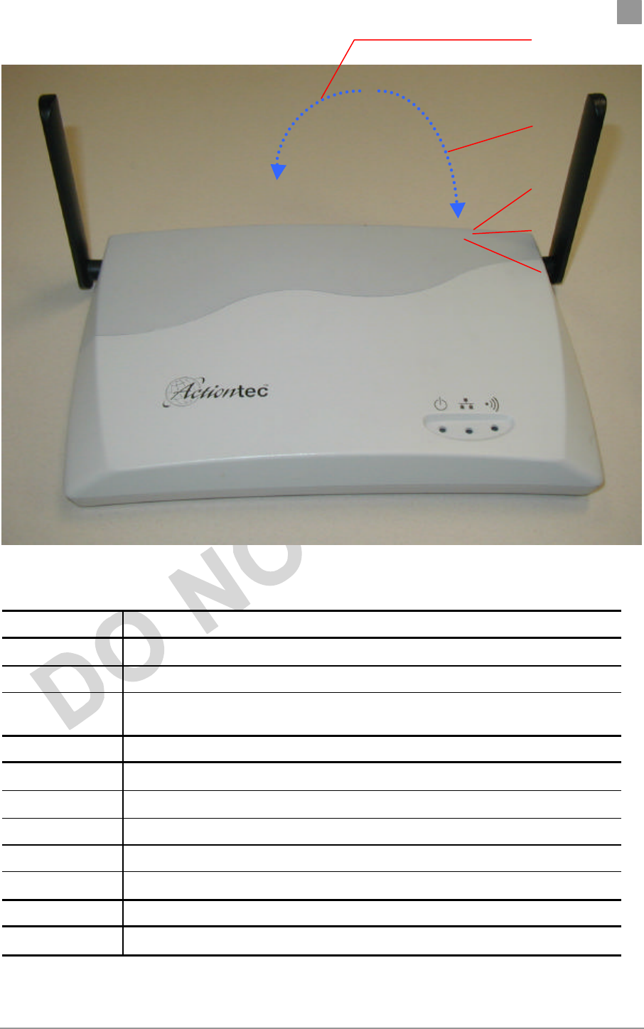
The top panel of the AP provides 3 LEDs for status indication, and a pair of side-
mounted antennas that rotate 180° for alternative reception positioning and
compact packaging.
WARNING: To ensure compliance with FCC FR exposure requirements,
position the AP so that its antenna is separated by at least 20 centimeters (cm)
from all persons.
Refer to Table 1-1 for a description of the functionality of each LED.
PRELIMINARY Chapter 1
Actiontec Electronics, Inc. COMPANY CONFIDENTIAL
Figure 1-1. Access Point Top Panel
Table 1-1. LED Functionality
LED 1 Description
Off No Power
On Power On and Ready for Operation
Blink Power On but Not Ready for Operation—at initial power on or reset, this indicates
self-test or software loading; at other times, this indicates a system fault
LED 2 Description
Off No Ethernet Link Detected
Green On 100 Mbps Link Detected but No Activity
Green Blink 100 Mbps Link Activity—blink rate is proportional to activity
Amber On 10 Mbps Link Detected but No Activity
Amber Blink 10 Mbps Link Activity—blink rate is proportional to activity
LED 3 Description
Off Wireless Link Disabled
LED 1 (Power Status)
LED 2 (Ethernet Link)
LED 3 (Wireless Link)
Fold this way for storage
and packaging
Fold this way for
wall mount
PRELIMINARY Chapter 1
Actiontec Electronics, Inc. COMPANY CONFIDENTIAL
LED 1 Description
Very Slow Blink Looking for Network Association
Slow Blink Associated with Network but No Activity
Fast Blink Associated with Network—blink rate is proportional to activity
H. Rear Panel
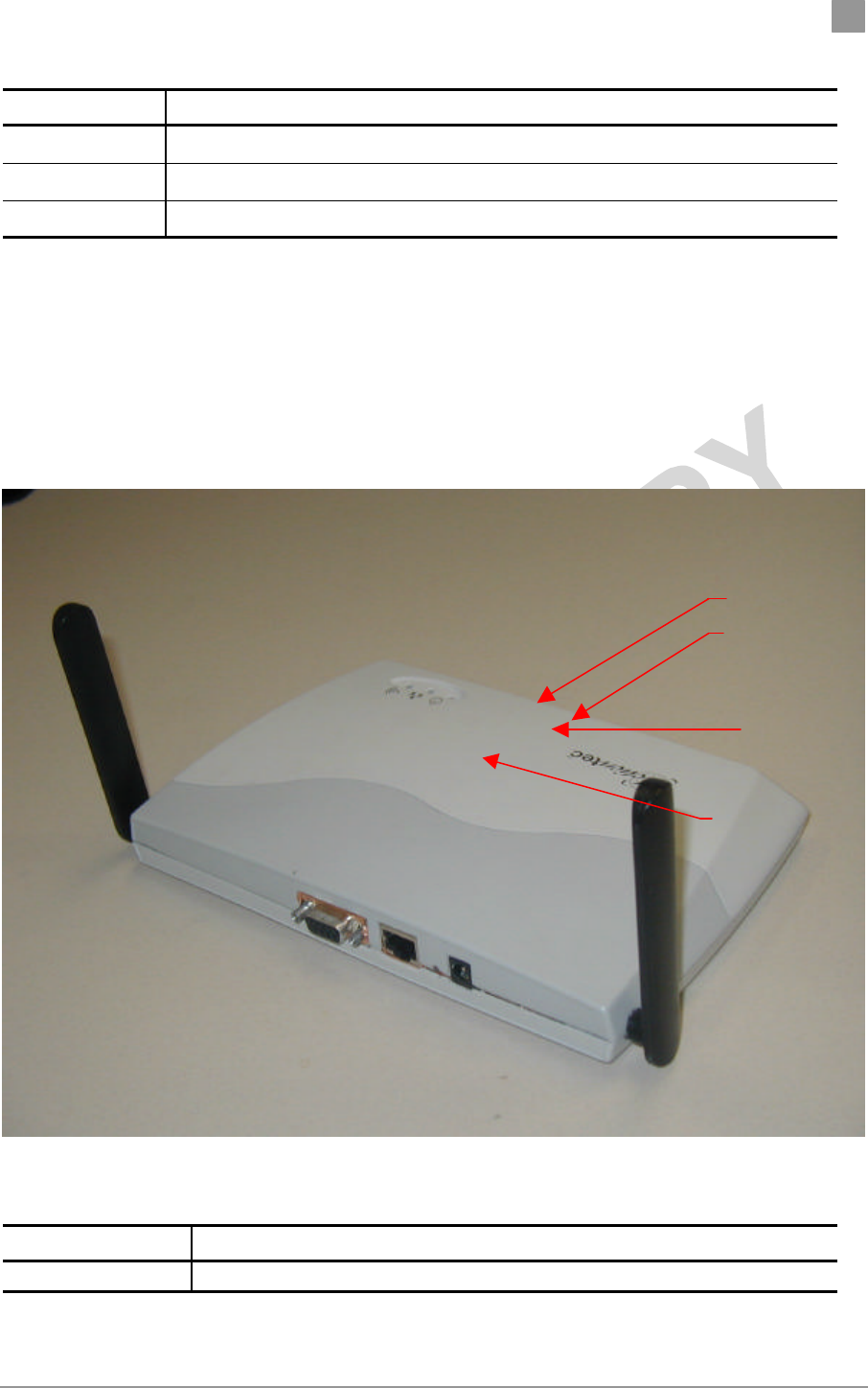
The rear panel of the AP (see Fig ref) provides an RS-232 serial interface, an RJ–45
Ethernet jack, a reset button, and a power supply connector (see Figure 1-2). Table
1-2 describes each connection and its function.
Figure 1-2. Access Point Rear View
Table 1-2. Rear Panel Descriptions
Item Description
RS
-
232 Serial
Interface connector
Provides configuration of
the AP through a terminal or PC (serial cable
provided), and external connectivity to devices such as analog modems.
RS-232 Serial Connector
RJ-45 Ethernet Connector
Reset Button
Power Supply Connector

PRELIMINARY Chapter 1
Actiontec Electronics, Inc. COMPANY CONFIDENTIAL
Item Description
Interface connector provided), and external connectivity to devices such as analog modems.
Selectable serial interface speeds up to 115 Kbps (default is 9600 baud, 8 data
bits, one stop bit, and no parity).
RJ-45 Ethernet
connector Provides 10/100 Mbps connectivity to a wired Ethernet LAN.
Reset button Manual push-button to reset processor, memory, and PCI devices.
Power Supply
connector Connection for the provided 3.3 V power supply.

PRELIMINARY
Actiontec Electronics, Inc. COMPANY CONFIDENTIAL
2.
AP Network Attachment
and Configuration
This section provides procedures for connecting and configuring the AP to a Host
PC (HPC). Configuration can be performed either from a web browser accessing
the built-in web server, or by entering command through the serial port command
line interface (CLI). For detailed information on using the web server, refer to AP
Web Server in Appendix A. For detailed information on using CLI
AP Network Connections
Connect your HPC to the AP using one of the following two methods:
Use an Ethernet crossover cable (not supplied) to connect directly to the Ethernet
port of the HPC.
15. Use standard Ethernet cables (not supplied) to connect through a hub or
Ethernet switch. Follow these steps to establish the network connections:
17. Attach the supplied serial cable from the AP RS-232 serial interface to the HPC serial
COM port.
18. Connect the AP Ethernet port to the HPC Ethernet card through the Ethernet
hub/switch or an Ethernet crossover cable.
19. Plug in the provided 3.3 V power supply to the AP power supply connector.

PRELIMINARY Chapter 2
Actiontec Electronics, Inc. COMPANY CONFIDENTIAL
AP Initial Configuration
When you have completed loading the operating system software, initially
configure the AP for its channel frequency and Service Set Identifier (SSID)
unique to your application. This configuration can be done either through a web
browser with access to the built-in AP web server, or by issuing commands
through the serial port command line interface (CLI).
You can fully configure the AP at any time to tailor the AP for your application
environment. For more information on configuring the AP using the web
browser, refer to Appendix A, AP Web Server. For more information on using the
CLI, refer to Appendix B,
The following description illustrates the use of the web browser. For information
on using the CLI, refer to Command-Line Interface on page 2-4.
i. Web Browser
Follow these steps to configure the channel frequency and SSID using a
web browser:
1. Launch a web browser (Netscape Navigator or Internet Explorer are
examples of commonly used web browsers).
2. From the HPC, enter the IP address that is assigned to the AP as the URL
address, for example http://192.168.1.1.
20. Select the Actiontec Access Point Web Server hotlink.
21. A dialog box will appear that requests login authorization. When prompted, enter the
following information to log in:
Log in: Admin (case sensitive)
Password: ***

PRELIMINARY Chapter 2
Actiontec Electronics, Inc. COMPANY CONFIDENTIAL
Click OK to complete the login process
22. Select the Configuration hotlink from the navigation bar.
23. Enter the SSID (name or address) for the AP in the SSID field. The SSID must be 1
through 32 characters in length.
You can have more than one AP in a single SSID. If you are
configuring more than one AP in a single SSID, you must
specify a unique System Name for each AP within a single
SSID.
24. Specify the radio channel of operation of the AP by selecting the desired value from the
Radio Channel drop-down menu. This value specifies the frequency the stations (STAs)
under the AP are associating with in Infrastructure mode.
Note that the radio channel is specified using the IEEE 802.11a
standard. For example, channel 48 is the equivalent of 5.240
GHz. The formula below shows how the channel number is
derived:
Channel Number = Channel Frequency (in MHz) – 5000
MHz
5 MHz
25. Click Update to commit the changes.
PRELIMINARY Chapter 2
Actiontec Electronics, Inc. COMPANY CONFIDENTIAL
At this time you can also change other settings. Refer to
Appendix A, AP Web Server for more information about each
configuration option.
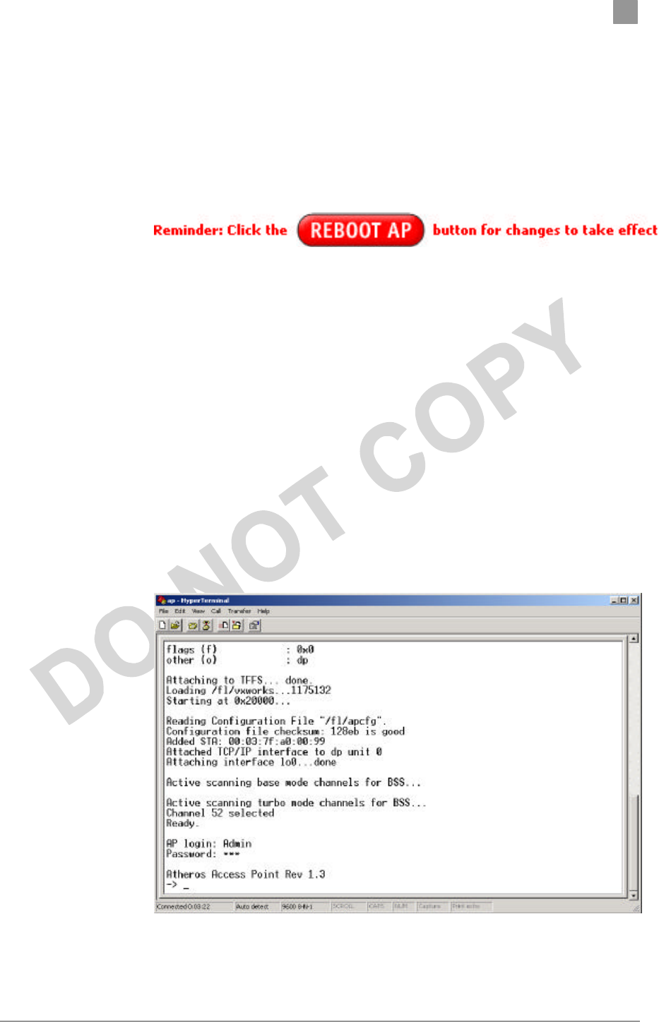
26. You must reboot the AP to enable any configuration change. To reboot the AP, click on
the REBOOT AP button that appears.
Command-Line Interface
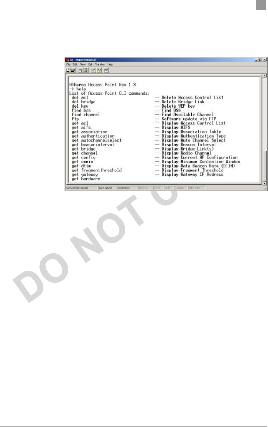
The following procedures show the steps required to configure the AP SSID and
channel frequency using the command-line (CLI) interface and HyperTerminal.
3. After the AP boots and the operating system software loads, press Enter
to invoke the AP login: prompt. When prompted, enter the following
information to log in:
Username: Admin (case sensitive)
Password: ***
27. Press Enter to complete the login process. The Actiontec Access Point Software revision
prompt will appear.

PRELIMINARY Chapter 2
Actiontec Electronics, Inc. COMPANY CONFIDENTIAL
28. Use the set ssid <SSID> command to specify the SSID.
29. Use the set channel <channel> command to change the radio channel.
30. Use the reboot command and then press Enter, which reboots the AP, to enable any
changes.
PRELIMINARY Chapter 2
Actiontec Electronics, Inc. COMPANY CONFIDENTIAL
49. To view CLI command options, use the help command or refer to Appendix B for details
about CLI options.

Preliminary Chapter 2
Actiontec Electronics, Inc. COMPANY CONFIDENTIAL
A
AP Web Server
You can configure the AP through either through a web browser interface to the
AP web server, or using the CLI through a serial interface. The web server resides
in the AP and is accessible from any STA that is connected to the AP
Infrastructure network.
Accessing the AP Web Server
Follow these steps to access the AP Web Server:
2. Launch a web browser (Netscape Navigator or Internet Explorer are
examples of commonly used web browsers).
3. From the HPC, enter the IP address that is assigned to the AP as the URL
address, for example http://192.168.1.1.
Customize the appearance of the Access Point Web Server
homepage by replacing the .GIF files used on the page. For
example, the .GIF file containing the full path filename for a
company logo can be replaced with one of your choice.
4. Select the Actiontec Access Point Web Server hotlink.
5. A dialog box appears that requests login authorization. When prompted,
enter the following information to log in:
Log in: Admin (case sensitive)
Password: ***

Preliminary Chapter 2
Actiontec Electronics, Inc. COMPANY CONFIDENTIAL
6. Click OK to complete the login process.
NOTE: Your browser must support frames and Javascript
must be enabled.
Preliminary Chapter 2
Actiontec Electronics, Inc. COMPANY CONFIDENTIAL
Configuration Windows
The Access Point Configuration windows allow you to view and edit
configuration information for the AP. The AP Web Server provides configuration
windows for:
16. General configuration parameters
17. General advanced configuration parameters
18. Shared keys
19. Per station privacy
20. Configuration scripts
21. Firmware updates
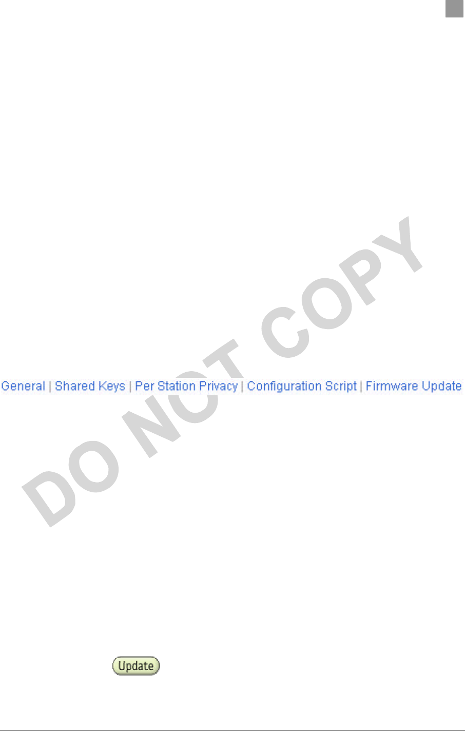
To access any of these AP configuration screens, select the desired hotlink from
the navigation bar on any configuration screen (see Figure A-3.)
Figure A-3. AP Configuration Window Navigation Bar
i. Working With Configuration Windows
The AP Configuration windows provide a user-friendly interface to help you
quickly configure your AP. After you make any additions or changes to any
configuration window, you must update the configuration file to save the
changes. The new configuration is not in effect until you reboot the AP.
Follow these steps to update configuration files:
1. Enter your configuration updates or changes in the appropriate
configuration fields.
2. Click Update

Preliminary Chapter 2
Actiontec Electronics, Inc. COMPANY CONFIDENTIAL
3. Click Reboot AP to make the changes effective.
The web server will lose connectivity with the AP Web Server
as the AP reboots.
To reestablish the connection with the AP Web Server, wait
until the AP has completed rebooting and navigate to the Web
Server to resume communication.
b. General Configuration Window
The General Configuration window allows you to enter general operating
information for the AP. Click on Configuration from any window to access the
General Configuration window.
Preliminary Chapter 2
Actiontec Electronics, Inc. COMPANY CONFIDENTIAL
At this time you can also change other settings.
Table A-1 summarizes the data fields on the AP General Configuration window.
Table A-1. AP General Configuration Window Field Descriptions
General Configuration
Field Description
SSID Identification of the AP. Enter a number or address
between 1 and 32 characters in length that the STAs
are associating with in Infrastructure mode. You can
specify more than one AP in an SSID. Use the
System Name field to uniquely identify each AP.
System Name Specifies a unique name for AP. Enter a unique text
string of up to 32 characters in length.
Radio Channel Select the desired frequency of operation from the
drop-down menu.
The radio frequencies that appear in the Radio
Channel drop
-
down menu are dependent on the
Regulato
ry Domain set specified.

Preliminary Chapter 2
Actiontec Electronics, Inc. COMPANY CONFIDENTIAL
General Configuration
Field Description
Regulatory Domain set specified.
Enable Auto Channel Select Select the checkbox to automatically search through
the frequency list to find an unused channel.
If a radio frequency is specified in the Radio
Channel field and the Auto Channel Select is
enabled, the designated frequency in the Radio
Channel field will be the first frequency auto-
attempted before scanning the remaining list.
Turbo Mode Allows transmission on two channels thereby
improving data rate.
To enable/disable Turbo Mode, click on the
appropriate Turbo button.
Enable Encryption Enables Wired Equivalent Privacy on the AP.
Authentication Type Specifies the authentication type used. “Open”
specifies no authentication. A STA must be
authenticated before it can be associated to an AP.
IP Address Specifies the IP address of the AP.
Subnet Mask Specifies the subnet mask for the AP.
Default Gateway Address Specifies the default gateway for the AP.
User Name Specifies the user name.
Password Specifies the password

Preliminary Chapter 2
Actiontec Electronics, Inc. COMPANY CONFIDENTIAL
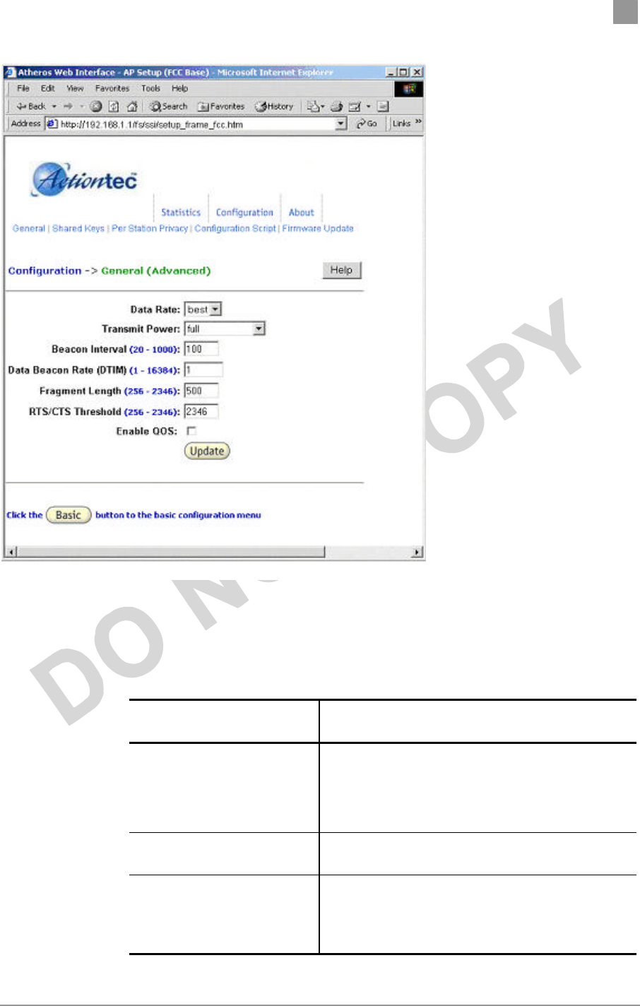
b. General Advanced Configuration Window
The General Advanced Configuration window allows you to enter
advanced, generic operating information for the AP. From
the AP General Configuration window, click on Advanced to
access the General Advanced Configuration window.
Table A-1 summarizes the data fields on the AP General Advanced Configuration
window.
Table A-1. AP General Advanced Configuration Window Field
Descriptions
Advanced Configuration
Field Description
Data Rate Specifies rate of data transmission. Select the
desired rate from the drop-down menu. The
Best selection will adapt the rate to the best
available.
Transmit Power Specifies the level of transmit power. Specify
the value of the transmit power from the drop-
down menu.
Decrease the transmit power if more than one
AP is co-located using the same channel
frequency.
Beacon Interval Specifies the Beacon Interval value. Enter a
value between 20 and 1000.
Data Beacon Rate Specifies the Data Beacon Rate. Enter a value
between 1 and 16384 that specifies the Delivery
Traffic Indication Message (DTIM).
Fragment Length Specifies the fragment length. Enter a value
between 256 and 2346.
RTS/CTS Threshold Specifies the value of the RTS/CTS threshold.
Enter a value between 256 and 2346.
Enable QOS Use the checkbox to allow the AP to participate
in a QOS environment.
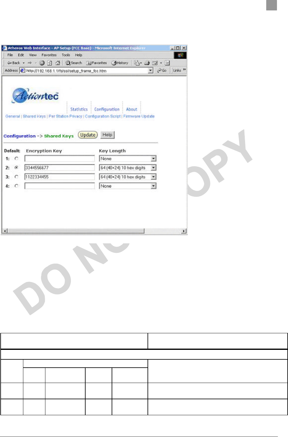
Shared Key Configuration
The Shared Key Configuration window allows you to specify Encryption
Key(s) if you enable encryption for the AP in the general configuration
window.
Preliminary Chapter 2
Actiontec Electronics, Inc. COMPANY CONFIDENTIAL
Use the Shared Key Configuration window to:
22. Select the default shared Encryption Key
23. Specify the key length
24. Specify the shared WEP keys
Refer to Table A-3 for examples of WEP configurations on the AP and
the STA.
Table A-3. Wired Equivalent Privacy Settings
WEP: Disable
WEP is disabled. Any STA can access to the
network
WEP: Enable
ACL
Shared
Key ACL MAC
address Key
Map Permission WEP
No Disable
No No No WEP is disabled. Any STA can access to the network.
Yes Disable
No No No Only STA with matched shared key can access to the
network.

Preliminary Chapter 2
Actiontec Electronics, Inc. COMPANY CONFIDENTIAL
Yes Enable
Yes No Allow 1. STA with matched MAC ID can access to the
network
2. Any STAs with matched shared key are also
allowed to access to the network.
Yes Enable
No Unique
key Allow 1. STA with matched unique key can access to the
network.
2. Any STAs with matched shared key are also
allowed to access to the network.
Yes Enable
Yes Unique
key Allow 1. STA with matched MAC ID and matched unique
key can access to the network.
2. Any STAs with matched shared key are also
allowed to access to the network.
x Enable
Yes No Deny STA with the matched MAC ID is blocked from
accessing the network.
x Enable
No Unique
key Deny STA with the matched unique key is blocked from
accessing the network.
x Enable
Yes Unique
key Deny STA with the matched MAC ID and unique key is
blocked from accessing the network.
Yes Strict x x x 1. Only STA with MAC ID and/or unique key
matched to the setup in ACL can access to the
network.
2. The STAs with only shared key are blocked
from accessing the network.
After entering or modifying the WEP configuration, you must click Update to
save the changes.
To view the configuration of a unique key, use the pull down menu to select the
unique key ID.
Per Station Privacy Configuration Window
Preliminary Chapter 2
Actiontec Electronics, Inc. COMPANY CONFIDENTIAL
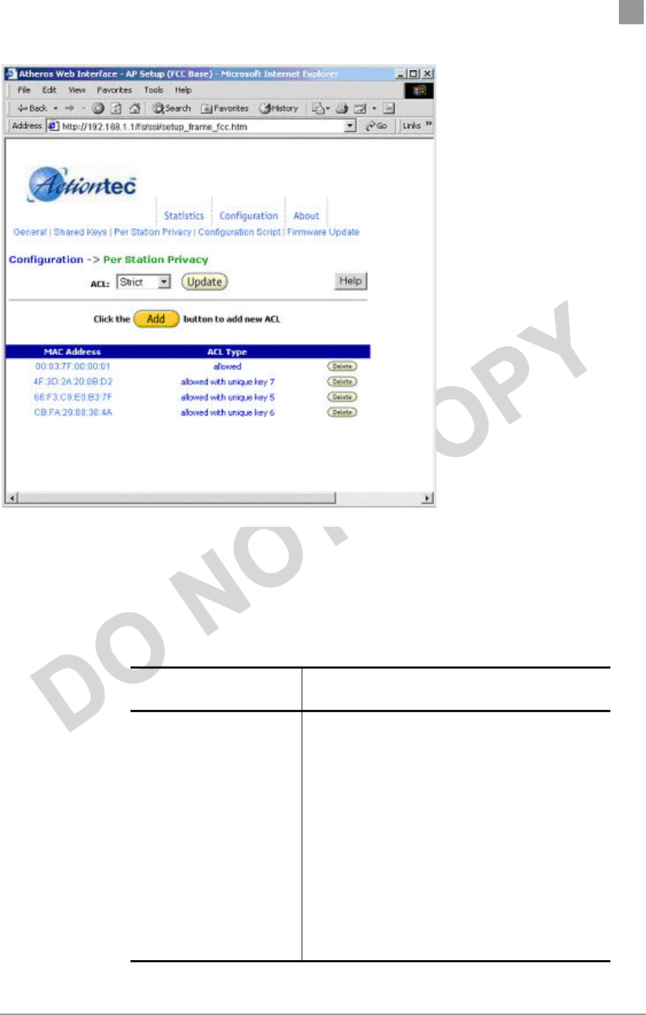
The AP Per Station Privacy Configuration window allows you to configure
access control lists for the AP
Table A-4 summaries the data fields on the Per Station Privacy window.
Table A-4. AP Per Station Privacy Field Descriptions
Per Station Privacy
Field Description
ACL Specifies the state of the Access Control List
(ACL). Use the drop-down menu to specify the
state of ACL, where:
1. Disable—Unrestricted Access—By
default, while checking of the ACL is
enabled, the access control list itself is
empty. This is the same as disabling the
checking on the ACL.
2. Enable—Restricted Access—An ACL
entry must exist if you wish to enable
ACL. While ACL is enabled, stations with
valid shared keys and stations with
matching “allow” entries on the ACL are
authenticated.

Preliminary Chapter 2
Actiontec Electronics, Inc. COMPANY CONFIDENTIAL
Per Station Privacy
Field Description
3. Strict—Restricted (w/ACL match)—
Requires an ACL entry that specifies the
station’s assigned unique key or the
station is denied association. In the strict
mode, stations with valid share keys and
not on the ACL are not authenticated.
The stations must have unique keys
defined and matching “allow” ACL
entries specified, in order to associate
with the AP.
MAC Address Specifies the MAC address for the STA to be
included in the ACL.
ACL Type Specifies the current state of each STA, where:
4. Allowed—Add/Modify MAC address to
the ACL.
5. Denied—Add/Modify MAC address to
the disabled ACL.
Follow these steps to configure privacy for stations:
1. Specify the ACL type from the drop-down menu. The Access Control List (ACL)
allows an administrator to perform security actions based on the client station
MAC address. Use this selection to allow or deny association with the AP and for
unique per station WEP key assignment.
3. Click on Add.
4. Enter the MAC address for the STA to be included on the access list. Click on Delete to
remove any configured STA from the access list.
5. Click Update to save your changes.
C. Script Configuration Window
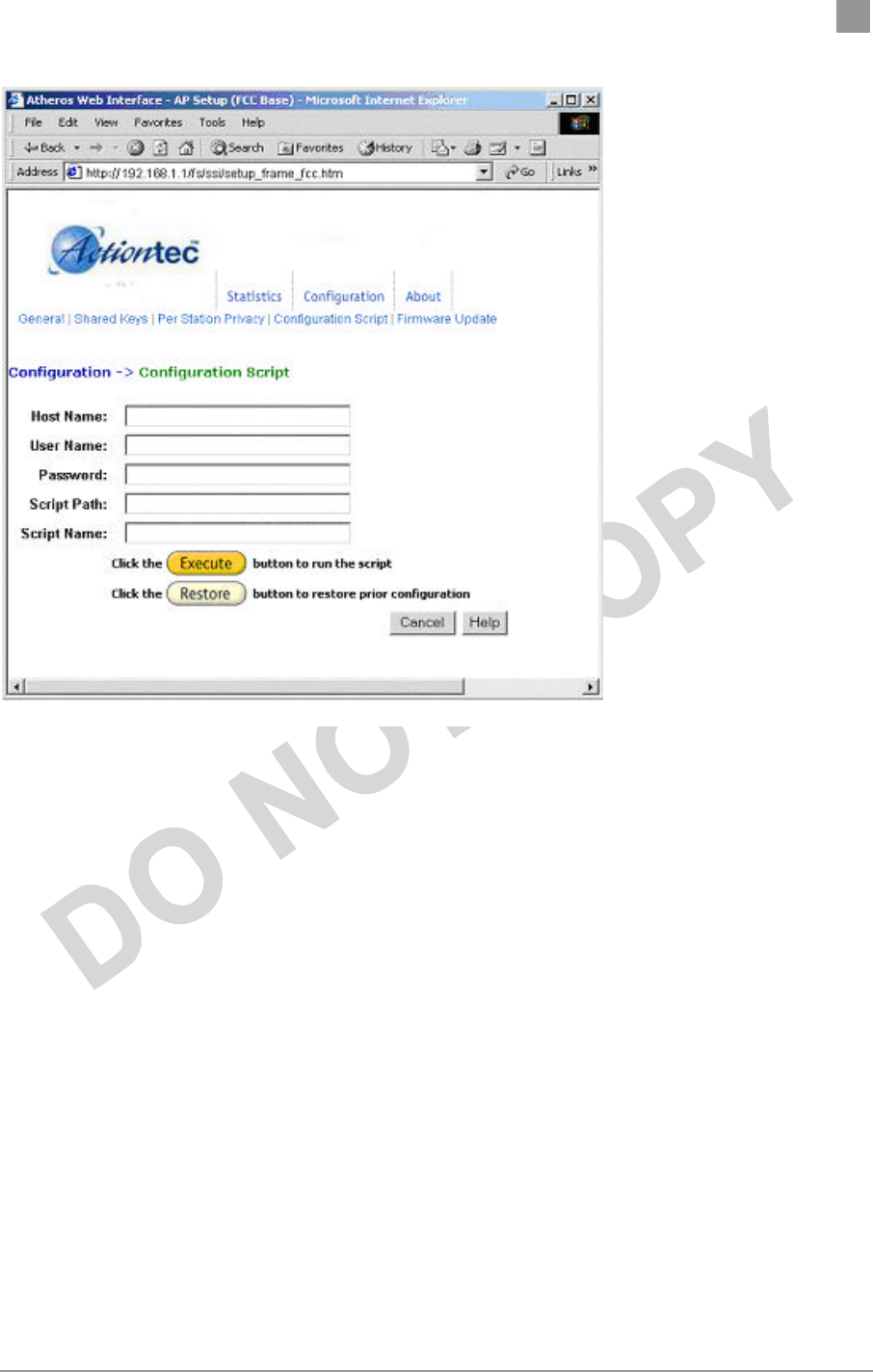
The Script Configuration window allows you to execute text scripts of CLI
commands. For example, you could construct a text script to enter the shared keys
for stations.
Preliminary Chapter 2
Actiontec Electronics, Inc. COMPANY CONFIDENTIAL
Follow these steps to use scripts:
1. Develop the scripts for your application.
2. Enter the host name where the script resides.
3. Enter the user name and password for the host.
4. Specify the script path and the script name in the data entry fields in the
Configuration Script window.
5. Click Execute to run the script.
If you wish to revert to the previous configuration, click
Restore.
Preliminary Chapter 2
Actiontec Electronics, Inc. COMPANY CONFIDENTIAL
Firmware Update Configuration Windows
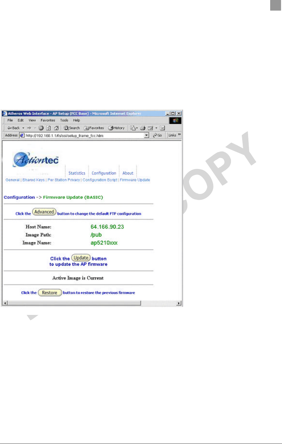
The Firmware Update Basic Configuration window allows you to view the FTP
location of new firmware. The default values for the Host Name, Image Path, and
Image Name appear in the window.
To access the Firmware Update window, click on Firmware Update in the
navigation bar.
Follow these steps to enable firmware updates:
1. From the Firmware Update Basic window, click on Advanced.
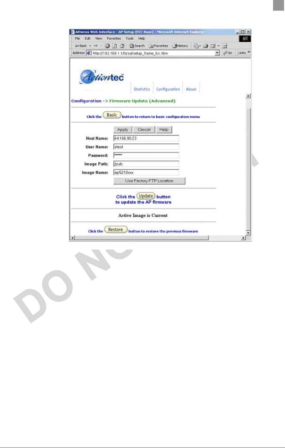
The Firmware Update Advanced Configuration window
allows you to enter new information on the FTP location of
new firmware or filename of the firmware.
Preliminary Chapter 2
Actiontec Electronics, Inc. COMPANY CONFIDENTIAL
2. Enter the Host Name, User Name, Password, Image Path, and Image
Name in the data-entry fields.
If you want to revert to the default-vendor values, click Use
Factory FTP Location.
3. Click Update Firmware to store the new firmware changes.
If you want to restore the previous firmware, click Restore.
Statistics Windows
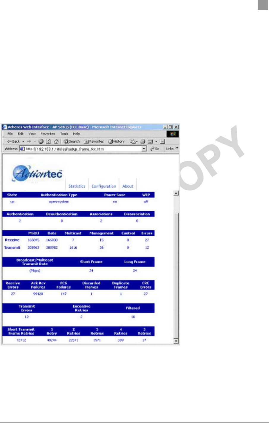
From the AP Web Server, choose the Statistics hyperlink to go to the Access Point
Statistics window. By default, this is the first window that appears once you enter
the AP Web Server.
Preliminary Chapter 2
Actiontec Electronics, Inc. COMPANY CONFIDENTIAL
The AP Statistics window allows you to view the assigned ID, MAC address, and
current state of the AP and all stations currently part of its BBS (Basic Service Set).
The top-level Statistics window automatically updates each minute.
i. AP Statistics
To view statistics on the AP, click on the MAC address hyperlink for the
desired AP in the Statistics window. The BSS Stats window
for the selected AP will appear.

Preliminary Chapter 2
Actiontec Electronics, Inc. COMPANY CONFIDENTIAL
The BSS Stats window for AP is divided into sections that provide the AP
configuration, Access Point SME statistics (station association information), or
Access Point (Transmit and Receive) Statistics. Refer to Table A-5 for a
description of the BSS Statistics for AP window fields.
Table A-5. BSS Stats Fields for AP Descriptions
BSS Stats Field Description
State Current state of the AP.
Authentication Type Specifies open-system or shared key.
Power Save Specifies the enabled state of the power save
option; either yes or no.
WEP Current state of Wired Equivalent Privacy; either
on or off.
Authentication/Deauthentication Number of times a STA attempted authentication
and deauthentication.
Association/Deassociation Number of times a STA attempted associations
and deassociations.
MSDU Maximum Service Data Unit. Specifies the
number of packets sent and received by the AP.
Data/Management/Control Packets can either be data, control, or
management. Specifies the number of packets
sent and received for each.
Multicast Specifies the number of multicast packets both
sent and received.
Errors Specifies the error count for both transmit
and receive.
Broadcast/Multicast Transmit
Rate Specifies the transmit rate of broadcast/multicast
packets.
Short Frame/Long Frame Specifies the number of transmitted short and
long frames. A short frame is less than 500 bytes;
long frames are equal to or greater than 500
bytes.
Receive Errors Specifies the number of receive errors.
Acknowledgement Receive
Failures Specifies the number of acknowledgement
receive errors.
FCS Failures Specifies the number of receive FCS failures.
Discarded Frames Specifies the number of receive
discarded frames.
CRC Errors Specifies the number of receive CRC errors.
Transmit Errors Specifies number of transmit errors.
Discarded Frames Specifies the number of transmit discarded
frames.

Preliminary Chapter 2
Actiontec Electronics, Inc. COMPANY CONFIDENTIAL
BSS Stats Field Description
frames.
Excessive Retries Specifies the number of transmit excessive
retries.
Short Transmit Frame Retries Specifies the number of short transmit frame
retries.
Retries Specifies the state of transmit retries for each
type.
The AP Stats window automatically updates every five seconds.
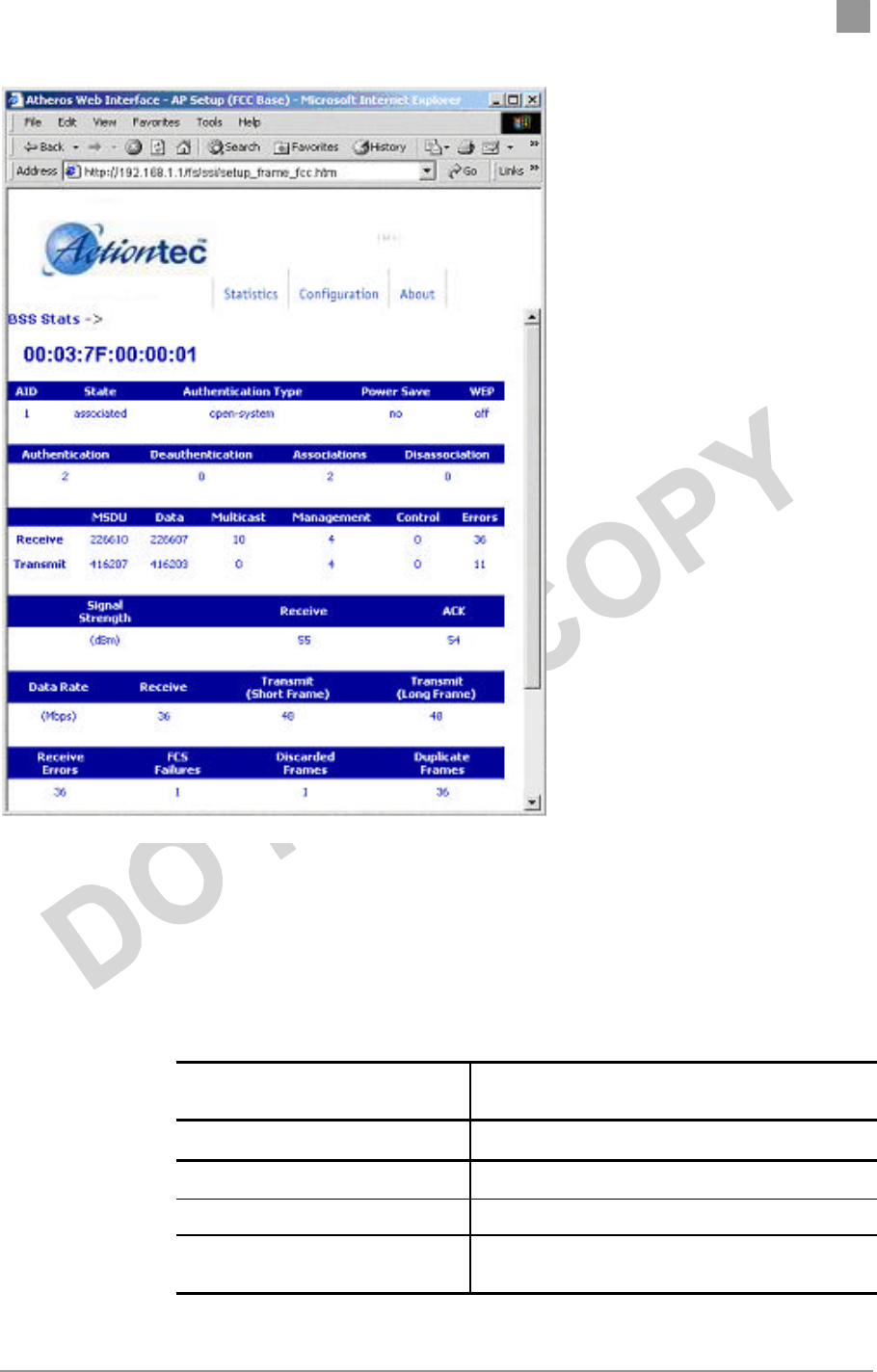
ii. Station Statistics
To view statistics on the any station (STA), click on the MAC address
hyperlink for the desired STA. The BSS Stats window for the
selected STA will appear.
Preliminary Chapter 2
Actiontec Electronics, Inc. COMPANY CONFIDENTIAL
The BSS Stats window for stations provides the station configuration and
statistics for the selected station.
Table A-6 summarizes the information fields on the BSS Stats window for
an STA.
Table A-6. BSS Stats Fields for STA Descriptions
BBS Stats Window for STA
Field Description
AID The ID of the station.
State Current state of the STA.
Authentication Type Specifies open-system or shared key.
Power Save Specifies the enabled state of the power save
option; either yes or no.

Preliminary Chapter 2
Actiontec Electronics, Inc. COMPANY CONFIDENTIAL
BBS Stats Window for STA
Field Description
WEP Current state of Wired Equivalent Privacy; either
on or off.
Authentication/Deauthentication
Number of times a STA attempted
authentication and deauthentication.
Association/Deassociation Number of times a STA attempted associations
and deassociations.
MSDU Maximum Service Data Unit. Specifies the
number of packets sent and received by the STA.
Data/Management/Control Packets can either be data, control, or
management. Specifies the number of frames.
Multicast Specifies the number of multicast frames.
Errors Specifies the error count for both transmit and
receive sides.
Signal Strength Specifies the strength of the signal in dBm.
Receive Specifies the strength of received frames in dBm.
ACK Specifies the strength of transmitted frames in
dBm.
Rate Specifies the data rate in megabits per second
(Mbps).
Receive Specifies the rate of the received data.
Transmit Short Frame/Long Frame
Specifies the rate of transmitted short and long
frames. A short frame is less than 500 bytes; long
frames are equal to or greater than 500 bytes.
Specifies the number of transmit frames of each
type.
Receive Errors Specifies the number of receive errors.
FCS Failures Specifies the number of FCS failures.
Short Transmit Frame Retries Specifies the number of short transmit frame
retries.
Retry 1-15 Specifies the number of retries for each retry
group.