Actiontec Electronics PK5000 ADSL2+ with 4-Port Ethernet Wireless Gateway User Manual
Actiontec Electronics Inc ADSL2+ with 4-Port Ethernet Wireless Gateway
User Manual

Actiontec
PK-5000
Wireless DSL Gateway
User Manual

1
Introduction
Thank you for purchasing the Wireless DSL Gateway. The Gateway is the simplest
way to connect computers to a high-speed broadband connection. This easy-to-use
product is perfect for the home office or small business. If you want to take your
computing to the next level, the Wireless DSL Gateway is sure to be one of the keys
to your success.
Minimum System Requirements
s !CTIVEDSL service
s #OMPUTERWITHAN10 Mbps or 10/100 Mbps Ethernet connection, or USB
connection
s -ICROSOFT7INDOWS98 Second Edition (SE), Millennium Edition (Me), NT 4.0,
2000, XP, Vista
Mac OS 7.1+, 8.0+, 9.0+, OS X+
! Note: USB ,!. port is not supported with Microsoft Windows
NT 4.0, Windows Vista 64-bit, or Mac OS.
s )NTERNET%XPLORER4.0 or higher (5.x+ recommended) or Netscape Navigator
4.0 or higher (4.7+ recommended)
s 4#0)0 network protocol installed on each computer
1

2
Wireless DSL Gateway User Manual
Features
s 0LUGAND0LAYINSTALLATIONSUPPORTFORCOMPUTERSRUNNING7INDOWSOPER-
ating systems (98SE, Me, 2000, XP, and Vista)
s !$3,7!. port (RJ-11)
s &ULLRATE!.3)4 Issue 2, ITU G.992.1(G.dmt) and G.992.2(G.lite)
standard compliance
s !UTOHANDSHAKEFORDIFFERENT!$3,flavors
s USB 1.1 device specification compliance
s 12 Mbps USB data rate (full speed) support
s "RIDGED%THERNETOVER!4-, PPP over !4-, PPP over Ethernet
s 0RECISE!4-traffic shaping
s IP packet routing and transparent bridge
s RIP-1, RIP-2, and static routing protocol support
s "UILTIN.!4, $(#0server
s DNS relay support
s 0!0#(!0 authentication, administrative passwords through Telnet
s 64-, 128-, and 256-bit 7%070! wireless ,!.security
s )%%% Ethernet standard compliance
s 10/100 Base-T Ethernet ports (4)
s &AST%THERNETFLOWCONTROLSUPPORT
s 7EBBASEDCONFIGURATIONSETUP
s &40 firmware upgradeable
s 7EBDOWNLOADSUPPORT
s 802.11b/g support
s WPS support

3
Chapter 1 Introduction
Getting to Know the Gateway
This section contains a quick description of the Gateway’s lights, ports, etc.
The Gateway has several indicator lights (LEDs) and a button on its front panel,
and a series of ports and switches on its rear panel.
Front Panel
The front panel of the Gateway features nine lights: Power, DSL, Internet,
Ethernet (4), USB, and Wireless.
Power Light
The Power light displays the Gateway’s current status. If the Power light glows
steadily green, the Gateway is receiving power and fully operational. When the
Power light is rapidly flashing, the Gateway is initializing. If the Power light is
glows red when the Power cord is plugged in, the Gateway has suffered a critical
error and technical support should be contacted.
DSL Light
The DSL light illuminates when the Gateway is connected to a DSL line.
Internet Light
When the Internet light glows steadily, the Gateway is connected to the DSL
provider. When it flashes, the Gateway’s built-in DSL modem is training for the
DSL service.
Ethernet Lights
The Ethernet lights illuminate when the Gateway is connected to one or more of
its yellow Ethernet ports.

4
Wireless DSL Gateway User Manual
USB Light
The USB light illuminates when the Gateway is connected via its USB port.
Wireless Light
The Wireless light illuminates when the Gateway is connected wirelessly (if the
Gateway’s Wireless feature is turned on).
WPS Button
The WPS button activates WPS7I&I0ROTECTED3ETUPONTHE'ATEWAY3EE
CHAPTERh#ONFIGURING7IRELESS3ETTINGSvFORMOREINFORMATIONABOUTWPS.
Rear Panel
The rear panel of the Gateway contains seven ports (Ethernet [4], Phone, USB, and
Power), as well as Reset and Power switches.
Ethernet Ports
The Ethernet ports are used to connect computers to the Gateway via Ethernet
cable. The Ethernet ports are 10/100 Mbps auto-sensing ports, and either a
straight-through or crossover Ethernet cable can be used when connecting to
the ports.
DSL Port
The DSL port is used to connect the Gateway to a DSL (Digital Subcriber Line)
connection.

5
Chapter 1 Introduction
Reset Switch
Depressing the Reset switch for one second will restore the Gateway’s factory
default settings. To reset the Gateway, depress and hold the Reset switch for
approximately ten seconds. The reset process will start after releasing the switch.
USB Port
The USB port is used to connect a computer to the Gateway via USB cable.
Power Port
The Power port is used to connect the Power cord to the Gateway.
! Warning: Do not unplug the Power cord from the Gateway
during the reset process. Doing so may result in permanent
damage to the Gateway.
Power Switch
The Power switch is used to power the Gateway on and off.

6
Wireless DSL Gateway User Manual
This page left intentionally blank.
7
Performing a
Quick Setup
This chapter is a guide through a quick set up of the Gateway, including how to
connect the Gateway to the ISP.
To complete the quick setup, have the Welcome Letter or ISP Worksheet handy. If
the document is not available, contact the ISP immediately.
Accessing Quick Setup Screens
To access the Quick Setup screens:
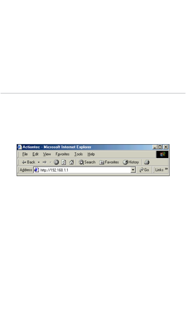
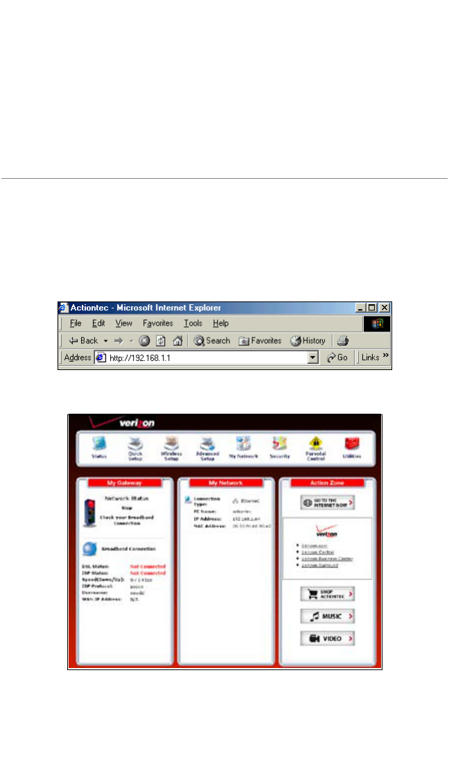
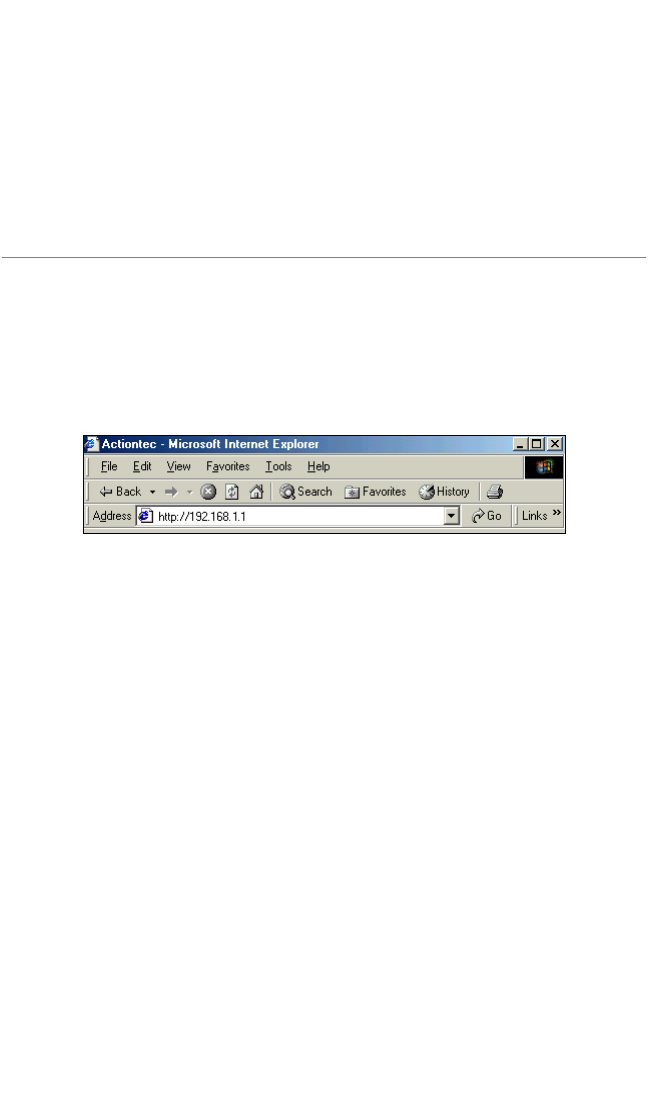
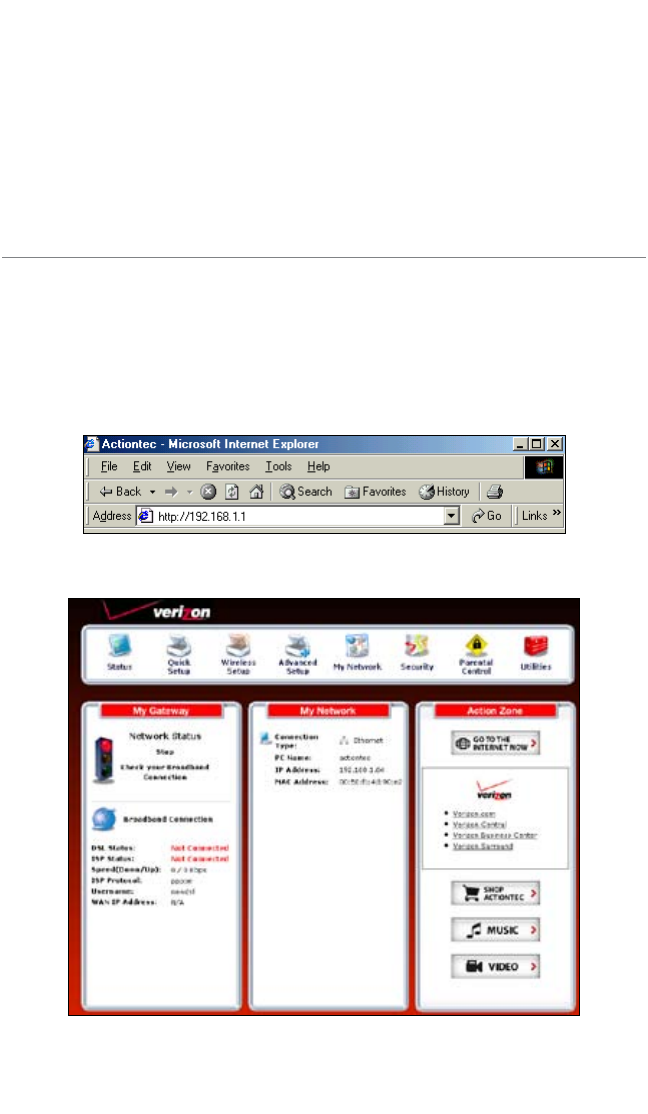
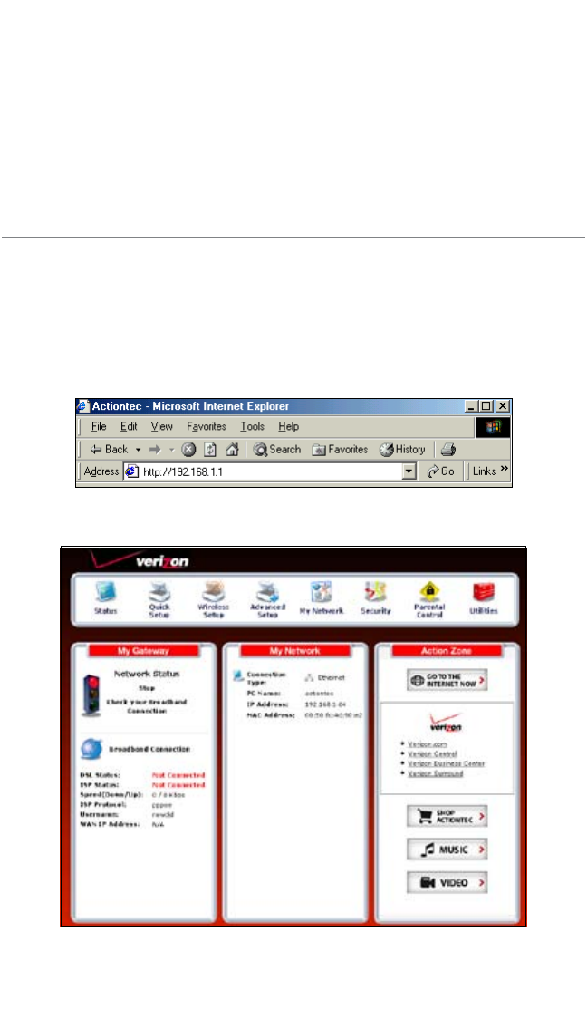
1. /PENA7EBBROWSER)NTHEh!DDRESSvTEXTBOXTYPE
http://192.168.1.1
then press Enter on the keyboard.
2
8
Wireless DSL Gateway User Manual
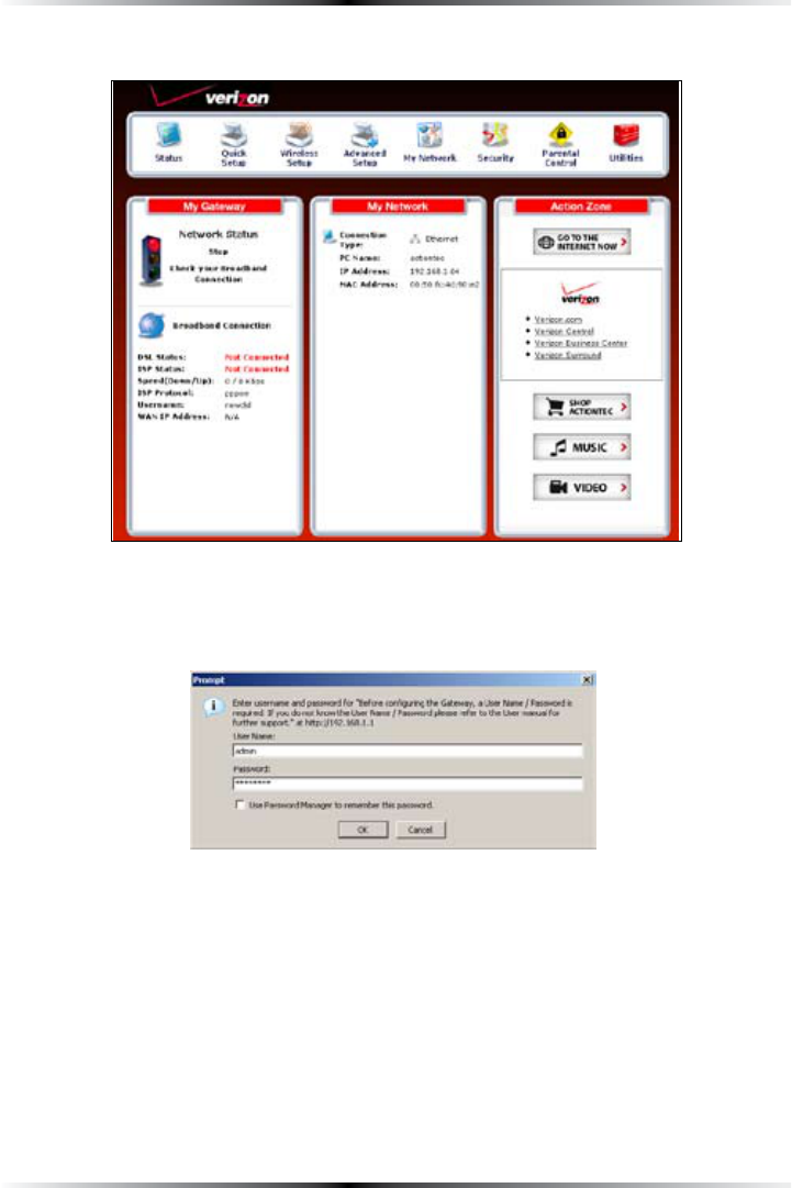
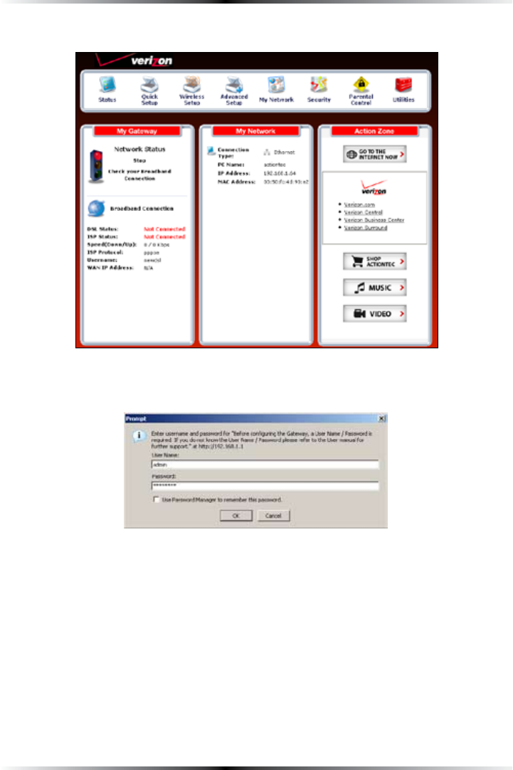
2. 4HEh(OMEvSCREENAPPEARS#LICKQuick Setup.
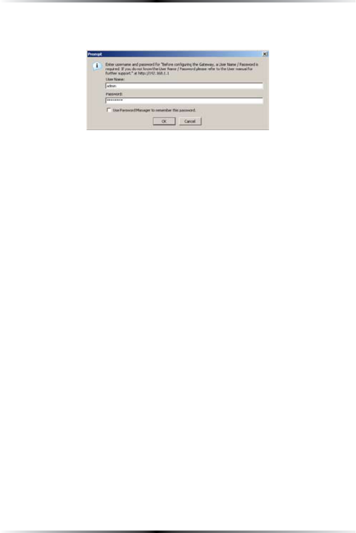
3. !LOGINWINDOWAPPEARS%NTERTHEUSERNAMEANDPASSWORDINTHEAPPROPRI-
ate text boxes, then click OK.
! Note: 4HEDEFAULTUSERNAMEIShADMINv4HEDEFAULTPASSWORDIS
hPASSWORDv
9
Chapter 2 Performing a Quick Setup
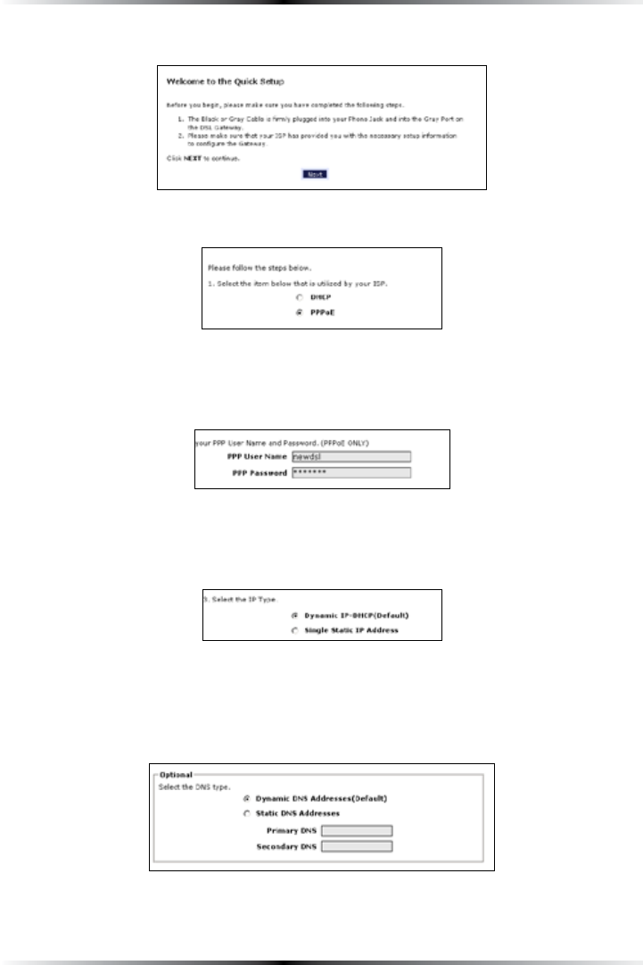
4. &OLLOWTHEINSTRUCTIONSINTHEh7ELCOMETOTHE1UICK3ETUPvSCREENTHENCLICKNext.
5. !TTHETOPOFTHENEXTWINDOWSELECT PPPoE or DHCP.
5a. If PPPoE was selected in step 5, the default user name and password are
entered in the appropriate text boxes.
If “$(#0vWASSELECTEDGOTOSTEP
5b. If PPPoE was selected in step 5, select the IP type (“Dynamic )0$(#0
;$EFAULT=vORh3INGLE3TATICIP !DDRESSv)F3INGLE3TATICIP !DDRESSWASSELECT-
ed, enter the address in the appropriate text box.
6. Optional - Select the DNS type (“Dynamic DNS !DDRESSES;$EFAULT=vOR
“Static DNS !DDRESSESv)F3TATICDNS !DDRESSESWASSELECTEDENTERTHEPRIMA-
ry and secondary DNS addresses in the appropriate text boxes. If unsure what
to enter in this section, contact the ISP.
10
Wireless DSL Gateway User Manual
7. #LICKApply at the bottom of the screen.
8. Read the instructions on the next screen. The Gateway is successfully
configured.
The Power light flashes rapidly while the Gateway restarts, then glows steadily
green when fully operational. The Internet light will also glow steadily green. The
Gateway is now configured and users can start surfing the Internet.
If an error appears, stating the Web browser was unable to connect to the Internet,
check the configuration settings. Ensure all the information required by the ISP is
entered correctly.
Changing the Password
To create or change the password allowing access to the Gateway’s Web
#ONFIGURATIONSCREENSFOLLOWTHESEINSTRUCTIONS
1. &ROMTHEh(OMEvSCREENSELECTSecurity.
2. 4HEh3ECURITYvSCREENAPPEARS3ELECTh!DMIN5SER.AMEAND0ASSWORDv
11
Chapter 2 Performing a Quick Setup
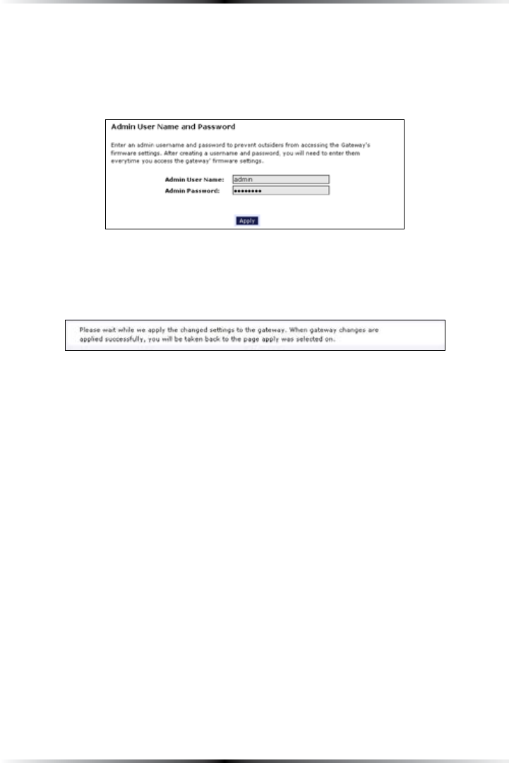
3. 4HEh#HANGE!DMIN5SERNAME0ASSWORDvSCREENAPPEARS%NTERANEW
5SERNAMEINTHEh!DMIN5SER.AMEvTEXTBOXTTHENENTERANEWPASSWORDIN
THEh!DMIN0ASSWORDvTEXTBOX-AKESURETOWRITEDOWNTHEUSERNAMEAND
password and keep it in a secure location. They will be needed to access the
'ATEWAYS7EB#ONFIGURATIONSCREENSINTHEFUTURE
4. #LICKApply at the bottom of the screen.
5. Read the instructions on the next screen. The user name and password are
successfully changed.
Once the Gateway has rebooted, the new user name and password are active. To
ACCESSTHE'ATEWAYS7EB#ONFIGURATIONSCREENSTHENEWUSERNAMEANDPASSWORD
must be entered.

12
Wireless DSL Gateway User Manual
This page left intentionally blank.
13
Viewing the
Gateway’s Status
!FTERCONFIGURINGTHE'ATEWAYTHE'ATEWAYSCONNECTIONANDNETWORKSTATUSCAN
BEVIEWED4HE)NTERNETCONNECTIONSTATUSISVIEWEDINTHEh"ROADBAND#ONNECTION
3TATUSvSCREENWHILETHENETWORKSTATUSISVIEWEDINTHEh-Y.ETWORKvSCREEN
Broadband Connection Status
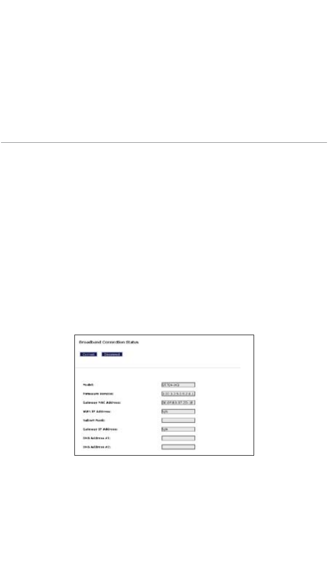
To view the Gateway’s connection statistics, select Status in the Home screen. The
h"ROADBAND#ONNECTION3TATUSvSCREENAPPEARS4HEREARETHREESECTIONSINTHIS
screen: General Statistics, PPP Status, and DSL Status.
!
Note: No settings (other than connecting or disconnecting from
the Internet by clicking on Connect or Disconnect) can be
CHANGEDFROMTHE"ROADBAND#ONNECTION3TATUSSCREEN
General Statistics
4HETOPSECTIONOFTHE"ROADBAND#ONNECTION3TATUSSCREENDISPLAYSGENERALSTATIS-
tics regarding the Gateway, including model number, firmware version, IP address,
and gateway IP address.
3
14
Wireless DSL Gateway User Manual
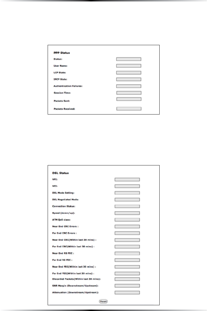
PPP Status
4HEMIDDLESECTIONOFTHE"ROADBAND#ONNECTION3TATUSSCREENDISPLAYSTHESTATUS
of the Gateway’s PPP connection, including user name, authentication failures,
and packets sent and received.
DSL Status
4HEBOTTOMSECTIONOFTHE"ROADBAND#ONNECTION3TATUSSCREENDISPLAYSTHESTATUS
of the Gateway’s DSL connection, including mode settings, connection status, and
NUMBEROFDISCARDEDPACKETS#LICKReset to refresh all statistics on this screen
15
Chapter 3 Viewing the Gateway’s Status
)NTHEMENUONTHELEFTSIDEOFTHE"ROADBAND#ONNECTION3TATUSSCREENTHEREARE
two other options available to view: NAT Table and Routing Table#LICKTOGEN-
erate the option of choice.
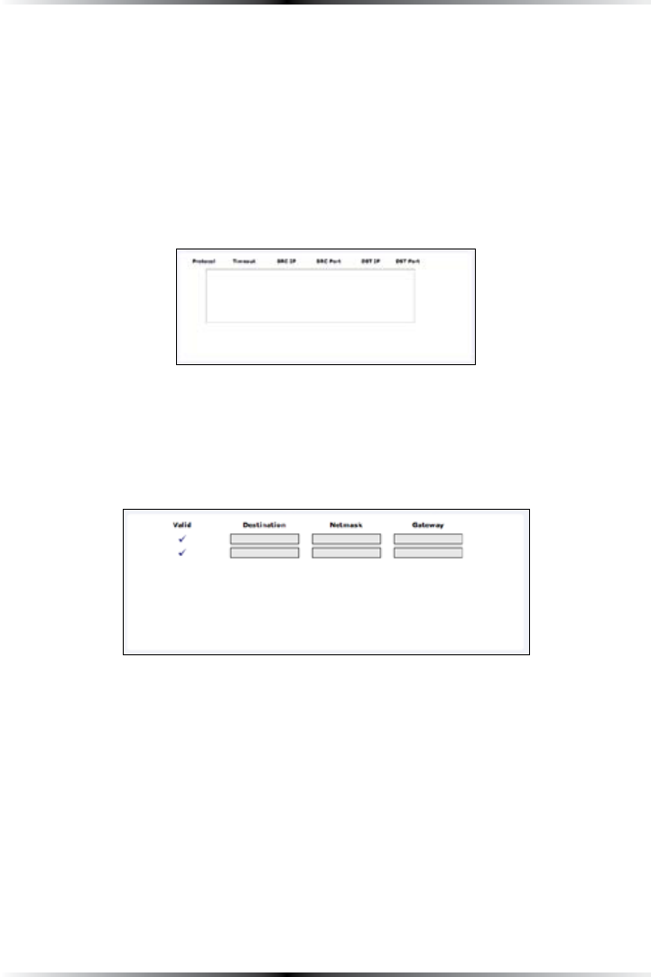
NAT Table
Selecting NAT TableGENERATESTHEh.!44ABLEvSCREEN4HISSCREENDISPLAYSANOVERVIEW
of the current list of open connections through .!4.ETWORK!DDRESS4RANSLATIONTHE
Gateway supports between the networked computers and the Internet.
Routing Table
Selecting Routing TableGENERATESTHEh2OUTING4ABLEvSCREEN4HISSCREENDISPLAYS
the an overview of the Gateway’s network routes.
16
Wireless DSL Gateway User Manual
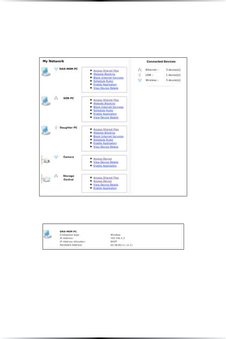
Network Status
To view the Gateway’s network status, select My Network INTHEh(OMEvSCREEN
4HEh-Y.ETWORKvSCREENAPPEARSLISTINGALLDEVICESCONNECTEDTOTHENETWORK
&ROMTHISSCREENVARIOUSSETTINGSCANBEACCESSEDINCLUDING7EBSITEBLOCKING
3CHEDULE2ULESAND%NABLE!PPLICATION
To view the network status of a particular device, click View Device Details for
THEDEVICE!NOVERVIEWOFTHEDEVICESNETWORKSTATUSAPPEARS
17
#
Configuring
Wireless Settings
This chapter explains how to set up the Gateway’s wireless network capabilities,
including setting up wireless security and viewing the wireless connection status.
Accessing Wireless Setup
To access the Wireless Settings configuration screens, follow these instructions:
1. /PENA7EBBROWSER)NTHEh!DDRESSvTEXTBOXTYPE
http://192.168.1.1
then press Enter on the keyboard.
2. 4HEh(OMEvSCREENAPPEARS#LICKWireless Setup.
4
18
Wireless DSL Gateway User Manual
3. !LOGINWINDOWAPPEARS%NTERTHEUSERNAMEANDPASSWORDINTHEAPPROPRI-
ate text boxes, then click OK.
! Note: 4HEDEFAULTUSERNAMEIShADMINv4HEDEFAULTPASSWORDIS
hPASSWORDv
19
Chapter 4 Configuring Wireless Settings
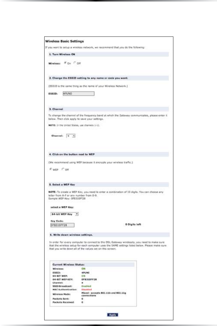
4. 4HEh7IRELESS"ASIC3ETTINGSvSCREENAPPEARS4OMODIFYASPECIFICCONFIGURA-
tion, click on its name in the menu bar on the left, or from the list in the mid-
dle of the screen.
20
Wireless DSL Gateway User Manual
Basic Wireless Setup
To perform a basic setup of a wireless network using the Gateway:
1. )NTHEh7IRELESS"ASIC3ETTINGSvSCREENTURNTHE'ATEWAYSWIRELESSRADIOONBY
selecting On.
2. #REATEANAMEFORTHEWIRELESSNETWORKANDENTERITINTHEhESSIDvTEXTBOX
3. 3ELECTACHANNELFROMTHEh#HANNELvDROPDOWNMENU)NTHEUnited States,
use channels 1-11.
4. !CTIVATEWEP (Wired Equivalent Privacy) to secure the wireless network by
selecting WEP.
5. #REATEABITWEP key by selecting 64-bit WEP Key from the “select a WEP
+EYvDROPDOWNMENUTHENENTERINGADIGITKEYINTHEh+EY#ODEvTEXT
box. The digits can be any letter from !&, and any number from 0-9.
6. Write down the Gateway’s wireless settings. To connect other devices to the
wireless network, the devices’ wireless settings must match the Gateway’s wire-
LESSSETTINGSEXACTLY#HECKTHEh#URRENT7IRELESS3TATUSvBOXAVAILABLEINANY
wireless setting screen) to view the Gateway’s wireless status and settings.
Wireless Advanced Settings
To access the Gateway’s wireless advanced settings screens, select Advanced
SettingsFROMTHEMENUONTHELEFTSIDEOFTHEh7IRELESS"ASIC3ETTINGSvSCREEN
21
Chapter 4 Configuring Wireless Settings
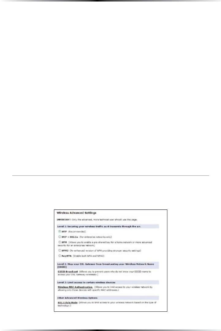
4HISGENERATESTHEh7IRELESS!DVANCED3ETTINGSvSCREEN)NTHISSCREENTHESECURITYOF
the wireless network can be activated and fortified.
Wireless Security
4HEFIRSTSECTIONOFTHE7IRELESS!DVANCED3ETTINGSSCREENINVOLVESWIRELESSSECURITY
(securing wireless traffic as it transmits through the air). The Gateway offers three
TYPESOFWIRELESSSECURITY7%07%0XAND70!
WEP
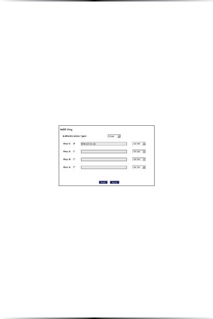
Selecting WEP INTHE7IRELESS!DVANCED3ETTINGSSCREENGENERATESTHEhWEP +EYv
screen. Here, the authentication type, encryption level, and WEP keys are entered
to activate WEP (Wired Equivalent Privacy) security encryption for the wireless
network.
Authentication Type - There are three authentication types: Open, Shared, and
Both. Open authenticaton allows any wireless-enabled device to recognize the
network, even if the WEP key is invalid. Shared allows only wireless-enabled
devices with the correct WEP key to recognize the network.
64-bit WEP - 64-bit WEP requires one or more keys, each key comprising five hexa-
decimal pairs. One key (Key 1) is automatically generated by the Gateway at start-
up, based on the Gateway’s -!#address. This key is also displayed on a sticker on
THEBOTTOMOFTHE'ATEWAY!HEXADECIMALDIGITCONSISTSOFANALPHANUMERICCHAR-
acter ranging from 0-9 or !&!NEXAMPLEOFA64-bit WEP key is: 4%!-D-68-72.
To create a new set of 64-bit WEP keys, activate one or more keys by clicking in the
appropriate circles, then enter five hexadecimal digit pairs in each activated Key
text box (Key 1-, Key 2-, Key 3-, Key 4-!FTERACTIVATING64-bit WEP, a computer
with wireless capability can join the network only if these same keys are entered in
the computer’s wireless encryption scheme.

22
Wireless DSL Gateway User Manual
128-bit WEP - 128-bit WEP requires one or more keys, each key comprising hexa-
DECIMALPAIRS!HEXADECIMALDIGITCONSISTSOFANALPHANUMERICCHARACTERRANGING
from 0-9 or !&!NEXAMPLEOFA128-bit WEP key is: D-44&%6#!1%&2E-
D#4-21-74-5D-B1. To create a 128-bit WEP key, activate Key 1 by clicking in the
appropriate circle, select “128BITvFROMTHEDROPDOWNLISTONTHERIGHTTHENENTER
hexadecimal digit pairs in the KeyTEXTBOX!FTERACTIVATING128-bit WEP, a com-
puter with wireless capability can join the network only if this key is entered in the
computer’s wireless encryption scheme.
256-bit WEP - 256-bit WEP requires one or more keys, each key comprising 29 hexa-
DECIMALPAIRS!HEXADECIMALDIGITCONSISTSOFANALPHANUMERICCHARACTERRANG-
ing from 0-9 or !&. To create a 256-bit WEP key, activate Key 1 by clicking in the
appropriate circle, select “256BITvFROMTHEDROPDOWNLISTONTHERIGHTTHENENTER
29 hexadecimal digit pairs in the KeyTEXTBOX!FTERACTIVATING256-bit WEP, a com-
puter with wireless capability can join the network only if this key is entered in the
computer’s wireless encryption scheme.
! Note: Not all wireless 0##ARDSSUPPORT128- or 256-bit WEP.
Ensure all 0##ARDSINSTALLEDINTHENETWORKEDCOMPUTERSSUP-
port 128- or 256-bit WEP before activating.
When finished with this screen, click Apply to save all changes. To return to the
7IRELESS!DVANCED3ETTINGSSCREENCLICKBack.
WEP+802.1x
!CTIVATINGWEP+802.1xINTHE7IRELESS!DVANCED3ETTINGSSCREENGENERATESTHE
“WEP+802.1xvSCREEN4HISSETTINGISFORENTERPRISENETWORKSONLYANDSHOULDBE
accessed by an experienced information systems specialist.
To set up WEP+802.1x security, enter the IP address of the 2!$)53server in the
“Server IP !DDRESSvTEXTBOXANDTHEh3ECRETvKEYFORCOMMUNICATIONBETWEEN
the 2!$)53SERVERANDTHE'ATEWAYINTHEh3ECRETvTEXTBOX4HEh0ORTvAND
h'ROUP+EY)NTERVALvVALUESSHOULDREMAINTHESAME
23
Chapter 4 Configuring Wireless Settings
When finished with this screen, click Apply to save all changes. To return to the
7IRELESS!DVANCED3ETTINGSSCREENCLICKBack.
WPA, WPA2, AnyWPA
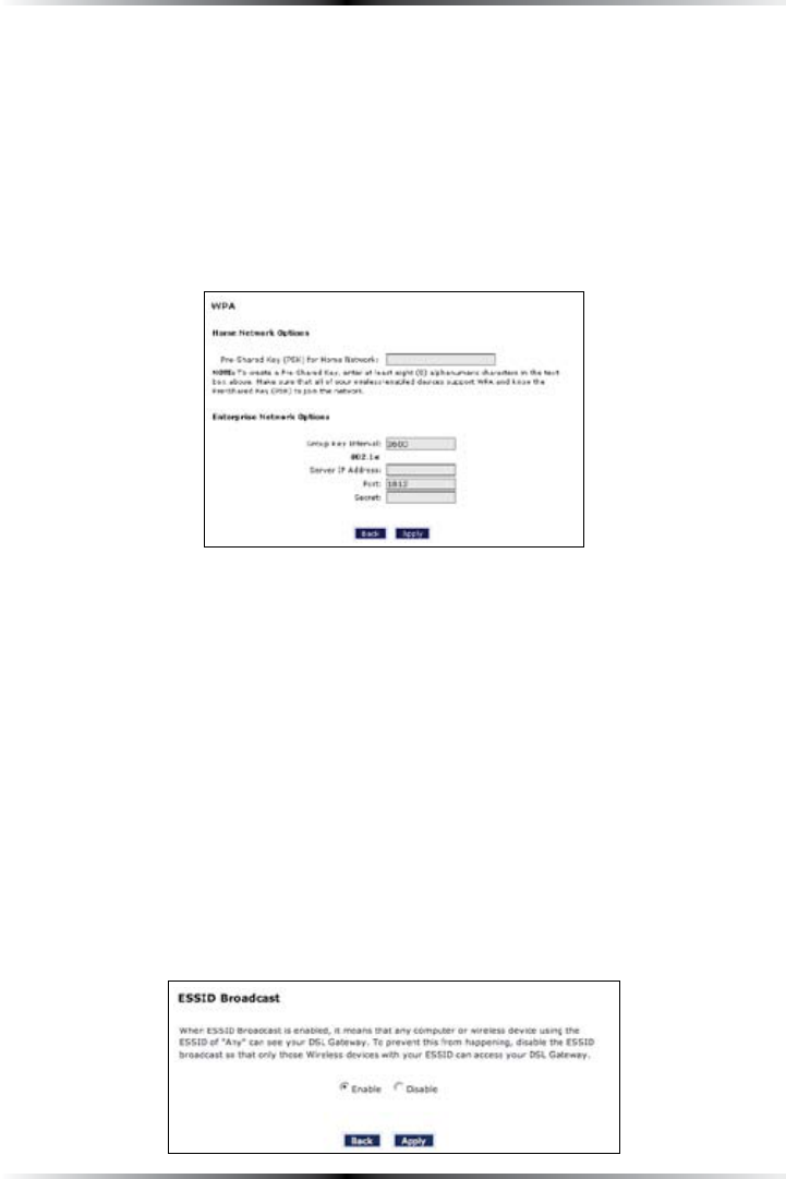
!CTIVATINGANYOFTHETHREEWPA7I&I0ROTECTED!CCESSOPTIONSin the Wireless
!DVANCED3ETTINGSSCREENGENERATESAhWireless 70!SettingsvSCREEN4HETHREE
70! options use identical procedures to activate, although 70! provides stron-
ger security than standard 70!. !NY70! activates both 70! and 70!.
There are two levels of 70!. “Pre-Shared Key (PSK) FOR(OME.ETWORKvISFOR
home network security. To set up a PSK (Pre-Shared Key), enter alphanu-
MERICCHARACTERSINTHETEXTBOX!LLWIRELESSENABLEDDEVICESMUSTSUPPORT70!
and know the PSK to join the network.
4HEh'ROUP+EY)NTERVALvh3ERVERIP !DDRESSvh0ORTvANDh3ECRETvTEXTBOXESARE
enterprise network specific, and should only be accessed by an information sys-
tems professional. See “WEP+802.1XvONTHEPREVIOUSPAGEFORMOREINFORMATION
When finished with this screen, click Apply to save all changes. To return to the
7IRELESS!DVANCED3ETTINGSSCREENCLICKBack.
ESSID Broadcast
Selecting ESSID Broadcast INTHE7IRELESS!DVANCED3ETTINGSSCREENGENERATESTHE
“ESSID BroadcastvSCREEN
24
Wireless DSL Gateway User Manual
To prevent a unwanted computers from joining the Gateway’s wireless network by
using an ESSID OFh!NYvSELECTDisable in the ESSID Broadcast screen. To broad-
cast the wireless network’s ESSID, select Enable.
When finished with this screen, click Apply to save all changes. To return to the
7IRELESS!DVANCED3ETTINGSSCREENCLICKBack.
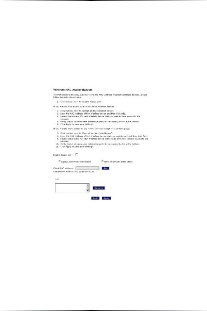
Wireless MAC Authentication
Selecting Wireless MAC AuthenticationINTHE7IRELESS!DVANCED3ETTINGSSCREEN
generates the “Wireless -!#!UTHENTICATIONvSCREEN
This feature allows the user to control the wireless ,!.network by denying or
allowing wireless access by specifying the -!#address of the wireless client(s)
allowed or denied access on the wireless network. To do this, follow the instruction
on-screen.
When finished with this screen, click Apply to save all changes. To return to the
7IRELESS!DVANCED3ETTINGSSCREENCLICKBack.
25
Chapter 4 Configuring Wireless Settings
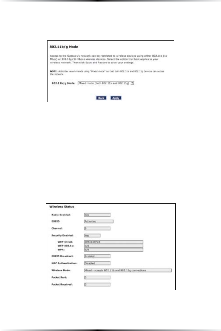
802.11b/g Mode
Selecting 802.11b/g ModeINTHE7IRELESS!DVANCED3ETTINGSSCREENGENERATESTHE
“802.11b/g ModevSCREEN
!CCESSTOTHE'ATEWAYSNETWORKCANBERESTRICTEDTOWIRELESSCLIENTSUSINGEITHER
the 802.11b or 802.11GWIRELESSADAPTERS#LICKONTHEDOWNARROWNEXTTOTHEDROP
down menu and select the desired option. We RECOMMENDUSINGTHEh-IXEDv
mode (the default option), which enables both 802.11b and 802.11g wireless clients
to join the network.
When finished with this screen, click Apply to save all changes.
Wireless Status
To view the Gateway’s wireless status and settings, select Wireless Status from the
MENUONTHELEFTSIDEOFTHEh7IRELESS"ASIC3ETTINGSvSCREEN
4HEh7IRELESS3TATUSvSCREENAPPEARSWHICHDISPLAYSALLOFTHESETTINGSOFTHE'ATEWAYS
wireless network settings.
26
Wireless DSL Gateway User Manual
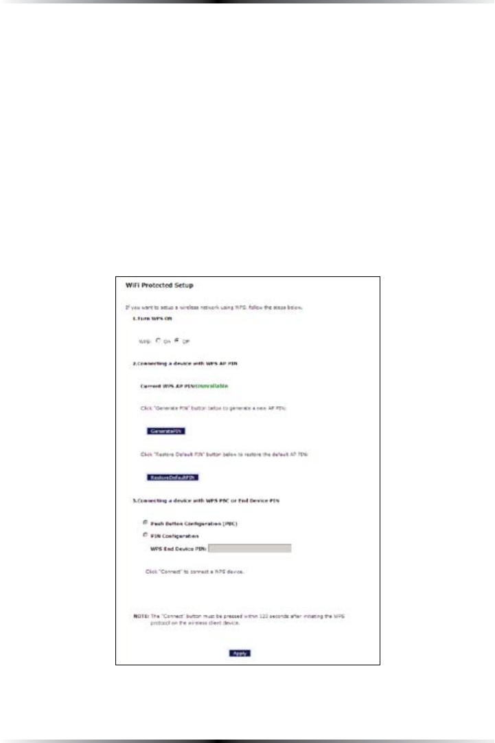
WPS (WiFI Protected Setup)
7I&I0ROTECTED3ETUP703PROVIDESANEASIERWAYTOSETUPAWIRELESSNETWORK
Instead of entering passwords or multiple keys on each wireless client (laptop,
printer, external hard drive, etc.), the Router can create a wireless network that
only requires pressing buttons (one on the Router, and one on the client [either
built-in, or on a compatible wireless card]) to allow wireless clients to join the
Router’s wireless network.
Activating WPS
To activate WPS on the Router:
1. &ROMTHE2OUTERS(OMESCREENCLICKWireless Setup, then select WPS from
THEMENUONTHELEFTSIDE4HEh7I&I0ROTECTED3ETUPvSCREENAPPEARS
2. !CTIVATE703BYCLICKINGTHEh/NvRADIOBUTTONUNDERh4URN703/.v

27
Chapter 4 Configuring Wireless Settings
3. #LICKApply at the bottom of the screen. The Router is now ready to accept
WPS clients on its wireless network.
Joining the WPS Wireless Network
4OJOINTHE703WIRELESSNETWORKPRESSTHEh7I&I0ROTECTED3ETUPvBUTTONONTHE
front panel of the Router, then press the WPS button on the wireless client. The
Router and client will search and locate each other, then auto-configure whatever
WIRELESSSECURITY70!ETCISBEINGUSED)TCANTAKEUPTOMINUTESFORTHE
Router and client to finish the connection procedure. When the connection pro-
ecedure has completed, the client will be on the secure wireless network.
!LTERNATIVELYACLIENTCANJOINTHE2OUTERS703WIRELESSNETWORKBYENTERINGTHE
Router’s WPS PIN number in the client’s wireless network setup GUI. The Router’s
703!00).NUMBERISDISPLAYEDINTHE7I&I0ROTECTED3ETUPSCREEN)FNO0).
appears, click Generate PIN to create one.

28
Wireless DSL Gateway User Manual
This page left intentionally blank.
29
#
Configuring
Advanced Settings
This chapter explains how to configure the Gateway’s advanced settings, such as
remote management, $(#0settings, and Quality of Service (QoS).
Accessing Advanced Setup Screens
4OACCESSTHE!DVANCED3ETUPSCREENSFOLLOWTHESEINSTRUCTIONS
1. /PENA7EBBROWSER)NTHEh!DDRESSvTEXTBOXTYPE
http://192.168.1.1
then press Enter on the keyboard.
5
30
Wireless DSL Gateway User Manual
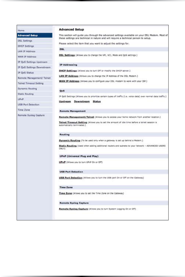
2. 4HEh(OMEvSCREENAPPEARS#LICKAdvanced Setup.
3. !LOGINWINDOWAPPEARS%NTERTHEUSERNAMEANDPASSWORDINTHEAPPROPRI-
ate text boxes, then click OK.
! Note: 4HEDEFAULTUSERNAMEIShADMINv4HEDEFAULTPASSWORDIS
hPASSWORDv
31
Chapter 5 Configuring Advanced Settings
4. 4HEh!DVANCED3ETUPvSCREENAPPEARS4OMODIFYASPECIFICCONFIGURATIONCLICKON
its name in the menu bar on the left, or from the list in the middle of the screen.
32
Wireless DSL Gateway User Manual
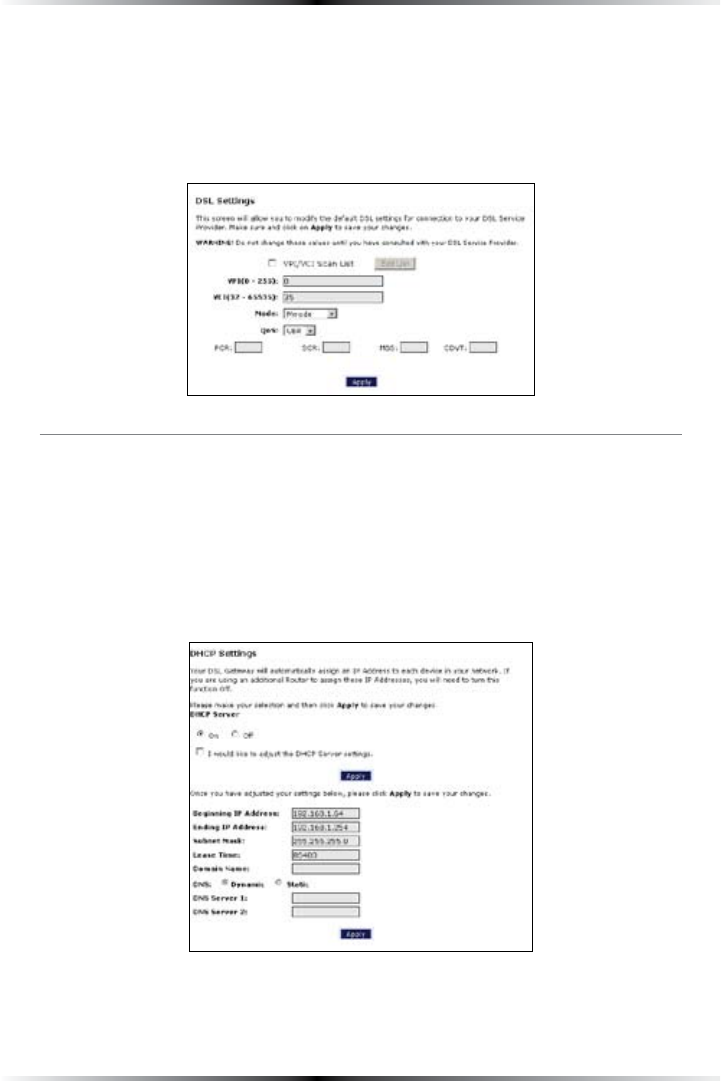
DSL Settings
To access DSL Settings, select DSL SettingsFROMTHEh!DVANCED3ETUPvSCREEN4HE
Gateway’s VPI, 6#), Mode, and QoS (Quality of Service) settings can be changed
from this screen, we recommend not changing these values without first consult-
ing the ISP.
DHCP Settings
Selecting DHCP SettingsINTHEh!DVANCED3ETUPvSCREENGENERATESTHEh$(#0
3ETTINGSvSCREEN4HE'ATEWAYHASABUILTIN$(#0$YNAMIC(OST#ONFIGURATION
Protocol) server that automatically assigns a different IP address to each computer
on the network, eliminating IP address conflicts.
The factory default setting is On. To disable the $(#0 Server, select Off, then
click Apply.

33
Chapter 5 Configuring Advanced Settings
We strongly recommend leaving the $(#0 Server option On. If the $(#0 Server
option is Off, ensure the IP addresses of the networked computers are on the same
subnet as the IPADDRESSOFTHE'ATEWAY&ORMOREINFORMATIONSEEh$(#0 Server
#ONFIGURATIONv
DHCP Server Configuration
#LICKINGINTHECHECKBOXLABELEDh)WOULDLIKETOADJUSTTHE$(#0SERVERSETTINGSv
activates the text boxes at the bottom of the $(#03ETTINGSSCREEN#HANGETHEIP
address range and DNS server information in these text boxes.
Beginning IP Address
This is the IP address at which the $(#0server starts assigning IP addresses. We
recommend keeping the factory default setting (192.168.1.64).
Ending IP Address
This is the IP address at which the $(#0server stops assigning IP addresses. We
recommend keeping the factory default settings (192.168.1.254).
The beginning and ending IP addresses define the IP address range of the
Gateway. If the default values are left intact, the Gateway supplies a unique IP
address between 192.168.1.64 and 192.168.1.254 to each computer on the net-
work. Note that the first three groups of numbers of the addresses are identical;
this means they are on the same subnet. The IP address of the Gateway must
be on the same subnet as the IPADDRESSRANGEITGENERATES&ORINSTANCEIFTHE
Gateway’s IP address is changed to .222.1, set the beginning IP address to
, and the ending IP address to .
Subnet Mask
Enter the IP address of the $(#0server’s subnet mask here.
Lease Time
This value represents the amount of time (in seconds) the $(#0server holds
onto a specific IP address.
34
Wireless DSL Gateway User Manual
Domain Name
This is the domain name provided by Verizon. If Verizon provided domain
name information, enter it here. If not, leave the text box intact.
DNS (Dynamic or Static)
This is the type of DNS server provided by Verizon. If Verizon provided DNS
server information, select the type here. If not, leave as is.
DNS Server 1
This is the primary DNS server provided by Verizon. If Verizon provided DNS
server information, enter it here. If not, leave the text box intact.
DNS Server 2
This is the secondary DNS provided by Verizon. If Verizon provided secondary
DNS server information, enter it here. If not, leave the text box intact.
When finished in this screen, click Apply to activate any changes made.
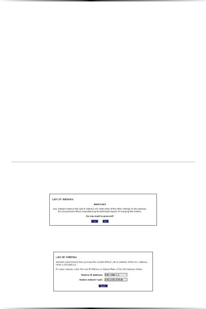
LAN IP Address
Selecting LAN IP AddressINTHEh!DVANCED3ETUPvSCREENCAUSESAWARNINGSCREEN
to appear.
Read the on-screen warning, then click Yes to continue.
The “,!.)0!DDRESSvSCREENAPPEARS
35
Chapter 5 Configuring Advanced Settings
The values in the “Modem IP!DDRESSvANDh-ODEM3UBNET-ASKvTEXTBOXESARE
the IP and subnet mask address of the Gateway as seen on the network. These val-
ues can be modified for your ,!.network, but we recommend keeping the default
factory settings (IP address 192.168.1.1; subnet mask address 255.255.255.0).
! Note: If the Gateway’s ,!.)0!DDRESSISMODIFIEDVERIFYTHE
$(#03ERVERRANGEISWITHINTHESAMESUBNET&ORMOREINFOR-
mation, see “$(#03ERVER#ONFIGURATIONv
When finished in this screen, click Apply to activate any changes made.
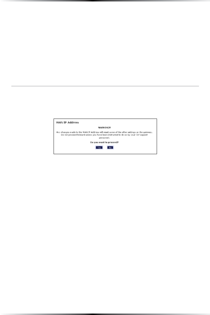
WAN IP Address
Selecting WAN IP AddressINTHEh!DVANCED3ETUPvSCREENCAUSESAWARNING
screen to appear.
Read the on-screen warning, then click Yes to continue.
36
Wireless DSL Gateway User Manual
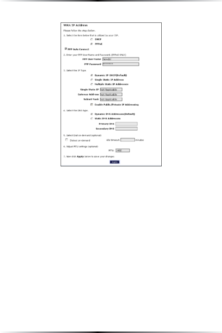
The “7!.)0!DDRESSvSCREENAPPEARS
7!.)0!DDRESSALLOWSMANUALSETUPOFTHEIP address of the Gateway. To do this:
! Note: Some DSL providers use PPPoE to establish communica-
tion with an end user. Other types of broadband Internet con-
nections (such as fixed point wireless) may use either $(#0or
static IP address. If unsure which connection is present, check
with Verizon before continuing.
1. Select “$(#0vORhPPPoEvDEPENDINGONTHETYPEOFCONNECTIONTHEISP uses.
If PPP !UTO#ONNECTISBEINGUSEDCLICKINTHEAPPROPRIATECHECKBOX
2. If using PPPoE was selected in step 1, enter the user name and password in the
appropriate text boxes.
3. Select the IP type. If “Single Static IP !DDRESSvwas selected, enter the IP
address in the “Single Static IPvTEXTBOX)Fh-ULTIPLE3TATICIP !DDRESSESvWAS
selected, enter the designated gateway IP address and subnet mask address in
THEh'ATEWAY!DDRESSvANDh3UBNET-ASKvTEXTBOXESRESPECTIVELY

37
Chapter 5 Configuring Advanced Settings
4. Enable Public/Private IP !DDRESSING4HISFEATUREISUSEDINCONJUNCTIONWITH
-ULTIPLE3TATIC)0!DDRESSES7HENSELECTEDTHE'ATEWAYUSES.!4for private
IP addressing for the ,!., allowing both public and private IP addressing to be
configured to the ,!.simultaneously, while the $(#0server is reserved for
PRIVATE)0ADDRESSING!LLCOMPUTERSUSINGPUBLICIP addresses must have the
public IP addresses statically assigned.
5. Select the DNS type. If static DNS address was selected, enter the primary DNS
address and, optionally, the secondary DNS address in the appropriate text
boxes.
6. Select Dialout on-demand (optional). To have the Gateway automatically
connect to the Internet whenever needed (when a Web browser is opened,
FOREXAMPLEACTIVATEh$IALOUTONDEMANDvBYCLICKINGINTHEAPPROPRIATE
check box. When Dialout on-demand is activated, the user can also set the
Gateway to disconnect from the Internet after a certain amount of idle time
(no Internet activity). To do this, enter the number of idle time minutes
(minimum 2 minutes) before disconnection occurs in the text box before
h-INUTESv
7. !DJUSTMTU settings (optional). Enter the maximum transmission unit (MTU)
value (in bytes) in this text box. This value corresponds to the largest physical
packet size the network is allowed to transmit. Packets larger than this size are
divided into smaller packets. It is recommended to leave this value set at the
default (1492).
When finished in this screen, click Apply to activate any changes made.

38
Wireless DSL Gateway User Manual
QoS Settings Upstream
Selecting QoS Settings UpstreamFROMTHEh!DVANCED3ETUPvSCREENCAUSESTHE
h1O35PSTREAM3ETTINGSvSCREENTOAPPEAR
QoS (Quality of Service) allows the prioritization of certain types of data traf-
fic (such as VoIP traffic) over other types of traffic (such as standard data). Both
upstream (data coming into the network) and downstream (data going out of the
network) traffic can be prioritzed using QoS.
Enable QoS
#LICKINGINTHISCHECKBOXACTIVATESDEACTIVATES1O3
Trusted Mode
)Fh4RUSTED-ODEvISACTIVATEDALLDATATRAFFICSETTOANIP precedence level of 5 will
be recognized as high priority traffic, regardless of IP or -!#address rule settings
(used for VoIP only).

39
Chapter 5 Configuring Advanced Settings
Total Available Bandwidth
Displays the total amount of available bandwidth (in kilobits per second).
High Priority Bandwidth
Enter the amount of high priority bandwidth to be used by the prioritized
traffic type (cannot exceed total available bandwidth).
Priority
!LWAYSSETTOh(IGHvANDCANNOTBECHANGED
Protocol
Select the data type being configured. Options: 4#0, UDP, )#-0.
Source
Identify the source device here, using the device’s IP or -!#address, then enter
appropriate value in text box. If IP is used, enter the netmask address, if applicable.
!PRIORITYPORTRANGECANALSOBEDEFINEDUSINGTHEh0ORT2ANGEvTEXTBOXES
Destination
Identify the destination device here, using the device’s IP address, then enter appro-
PRIATEVALUEINTEXTBOX%NTERTHENETMASKADDRESSIFAPPLICABLE!PRIORITYPORT
RANGECANALSOBEDEFINEDUSINGTHEh0ORT2ANGEvTEXTBOXES
Rule List
!FTERFINISHINGTHECONFIGURATIONOFTHE1O3SETTINGSCLICKAdd to save the settings
in the Rule List menu box. This collection of QoS settings can then be reused at a
future time. If deleting a QoS rule list, highlight it, then click Remove.
When finished in this screen, click Apply to activate any changes made.
40
Wireless DSL Gateway User Manual
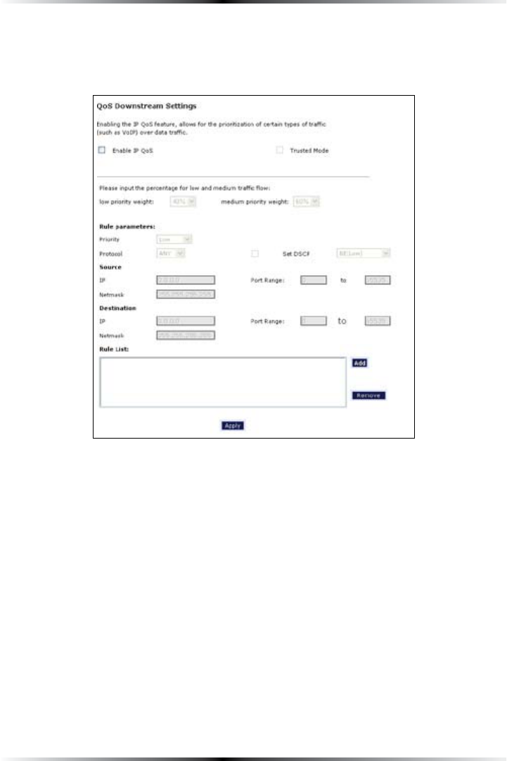
QoS Settings Downstream
Selecting QoS Settings Downstream FROMTHEh!DVANCED3ETUPvSCREENCAUSESTHE
h1O3$OWNSTREAM3ETTINGSvSCREENTOAPPEAR
4HEh1O3$OWNSTREAM3ETTINGSvSCREENISIDENTICALTOTHEh1O35PSTREAM3ETTINGSv
SCREENWITHTHEEXCEPTIONOFTHEh(IGH0RIORITY"ANDWIDTHvOPTION5SETHISSCREEN
to configure QoS for data going out of the network.
When finished in this screen, click Apply to activate any changes made.
41
Chapter 5 Configuring Advanced Settings
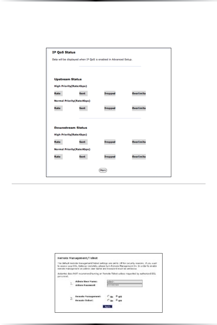
QoS Status
Selecting QoS Status FROMTHEh!DVANCED3ETUPvSCREENCAUSESTHEhIP 1O33TATUSv
screen to appear. This screen displays the status of QoS upstream and downstream
traffic, and differentiates both streams into high priority and normal priority traffic.
Remote Management/Telnet
Selecting Remote ManagementINTHEh!DVANCED3ETUPvSCREENGENERATESTHE
h2EMOTE-ANAGEMENT4ELENTvSCREEN2EMOTEMANAGEMENTALLOWSACCESSTOTHE
Gateway through the Internet via another computer, while Telnet allows access to
the Gateway using a computer running a Telnet program. we recommend leaving
the Remote Management and Telnet Off (the factory default setting). The Gateway
will be vulnerable to other users on the Internet if Remote Management or Telnet
is activated.

42
Wireless DSL Gateway User Manual
Remote Management
To access the Gateway from the Internet, activate Remote Management by select-
ing the appropriate On radio button and writing down the 7!.IP address of the
Gateway (see “7!.)0!DDRESSv/NACOMPUTEROUTSIDEOFTHENETWORKOPENA
Web browser and enter the Gateway’s 7!.)0 address in the address text box. The
Gateway’s Home screen (or a password prompt, if a password has been set) appears
in the browser window.
Telnet
4OACCESSTHE'ATEWAYVIA4ELNETACTIVATE4ELNETBYSELECTINGTHEAPPROPRIATEh/Nv
radio button and writing down the 7!.)0address of the Gateway (see “7!.)0
!DDRESSv/NACOMPUTEROUTSIDETHENETWORKRUNNINGA4ELNETPROGRAMENTERTHE
Gateway’s 7!.)0address to access the Gateway.
! Note: Before remote management or Telnet can be activated, the
administrator password must be set. To do this, go to the Home
screen, click Security, then select Admin User Name and
Password&OLLOWTHEINSTRUCTIONSINTHESUBSEQUENTSCREENS
When finished in this screen, click Apply to activate any changes made.
Telnet Timeout Setting
Selecting Telnet Timeout SettingINTHEh!DVANCED3ETUPvSCREENGENERATESTHE
h4ELNET4IMEOUT3ETTINGvSCREEN3ELECTAPERIODOFTIMEFROMTHECHOICESAVAILABLE
and the Telnet session will automatically terminate at that time. If no automatic
TERMINATIONISNEEDEDSELECTh.OIDLEDISCONNECTTIMEOUTv
When finished in this screen, click Apply to activate any changes made.
43
Chapter 5 Configuring Advanced Settings
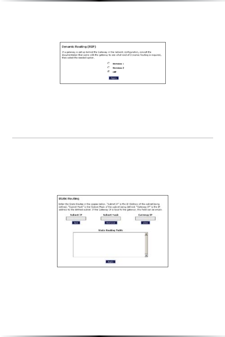
Dynamic Routing
Selecting Dynamic RoutingINTHEh!DVANCED3ETUPvSCREENGENERATESTHE
“Dynamic RoutingvSCREEN
If another gateway or router is set up behind the Gateway in the network configu-
ration, consult the documentation that came with the other gateway to see what
kind of Dynamic Routing is required, then select the needed option.
When finished in this screen, click Apply to activate any changes made.
Static Routing
Selecting Static RoutingINTHEh!DVANCED3ETUPvSCREENGENERATESTHEh3TATIC
2OUTINGvSCREEN%NTERTHESTATICROUTEADDRESSESINTHEIRRESPECTIVETEXTBOXES
then click Add4HEADDRESSWILLAPPEARINTHEh3TATIC2OUTING4ABLEv4OREMOVE
an address, highlight it by clicking on it in the Static Routing Table, then click
Remove.
When finished in this screen, click Apply to activate any changes made.
44
Wireless DSL Gateway User Manual
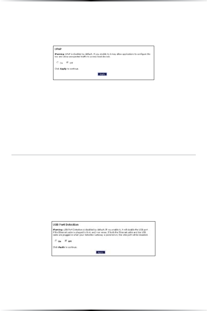
UPnP (Universal Plug and Play)
Selecting UPnPINTHEh!DVANCED3ETUPvSCREENGENERATESTHEhUPnPvSCREEN)N
this screen, the Universal Plug and Play option is turned on or off by activating the
appropriate circle.
Universal Plug and Play is a zero-configuration networking protocol that allows
hardware and software (such as Netmeeting) to operate more efficiently. If
Netmeeting is not running properly, activate UPnP.
! Note!CTIVATINGUPnPPRESENTSASLIGHTSECURITYRISK!FTER
finishing with the hardware or software using UPnP, we recom-
mend deactivating UPnP.
When finished in this screen, click Apply to activate any changes made.
USB Port Detection
Selecting USB Port DetectionINTHEh!DVANCED3ETUPvSCREENGENERATESTHEhUSB
0ORT$ETECTIONvSCREEN)NTHISSCREENTHEUSB port detection option is turned on or
OFFBYACTIVATINGTHEAPPROPRIATECIRCLEDEFAULTISh/FFv)FTHISOPTIONISTURNEDON
the USB port will be disabled if an Ethernet cable is plugged into the Gateway first, or
the Ethernet port will be disabled if the a USB cable is plugged into the Gateway first.
If this option is turned on when both an Ethernet and a USB cable are plugged into
the Gateway, the USB port will be disabled.
When finished in this screen, click Apply to activate any changes made.
45
Chapter 5 Configuring Advanced Settings
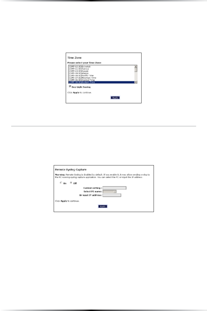
Time Zone
Selecting Time ZoneINTHEh#ONFIGURINGTHE!DVANCED3ETTINGSvSCREENGENERATES
THEh4IME:ONEvSCREEN)NTHISSCREENSELECTTHETIMEZONEINWHICHTHE'ATEWAY
ISBEINGUSED#LICKINTHEh$AY,IGHT3AVINGvCHECKBOXIF$AYLIGHT3AVINGS4IMEIS
currently in effect where the Gateway is being used.
When finished in this screen, click Apply to activate any changes made.
Remote Syslog Capture
Selecting Remote Syslog CaptureINTHEh!DVANCED3ETUPvSCREENGENERATESTHE
h2EMOTE3YSLOG#APTUREvSCREEN)NTHISSCREENTHEUSERCANCONFIGURETHE'ATEWAY
to allow a remote computer to access the Gateway’s system activity logs.
When finished in this screen, click Apply to activate any changes made.

46
Wireless DSL Gateway User Manual
This page left intentionally blank.
47
#
Configuring
Security Settings
This chapter explains how to configure the Gateway’s wired security capabilities,
including firewall settings, DMZ hosting, and network address translation.
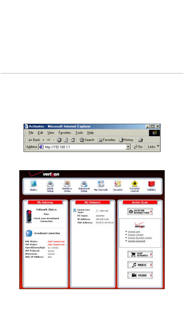
Accessing Wired Security Screens
To access the Wired Security configuration screens, follow these instructions:
1. /PENA7EBBROWSER)NTHEh!DDRESSvTEXTBOXTYPE
http://192.168.1.1
then press Enter on the keyboard.
2. 4HEh(OMEvSCREENAPPEARS#LICKSecurity.
6
48
Wireless DSL Gateway User Manual
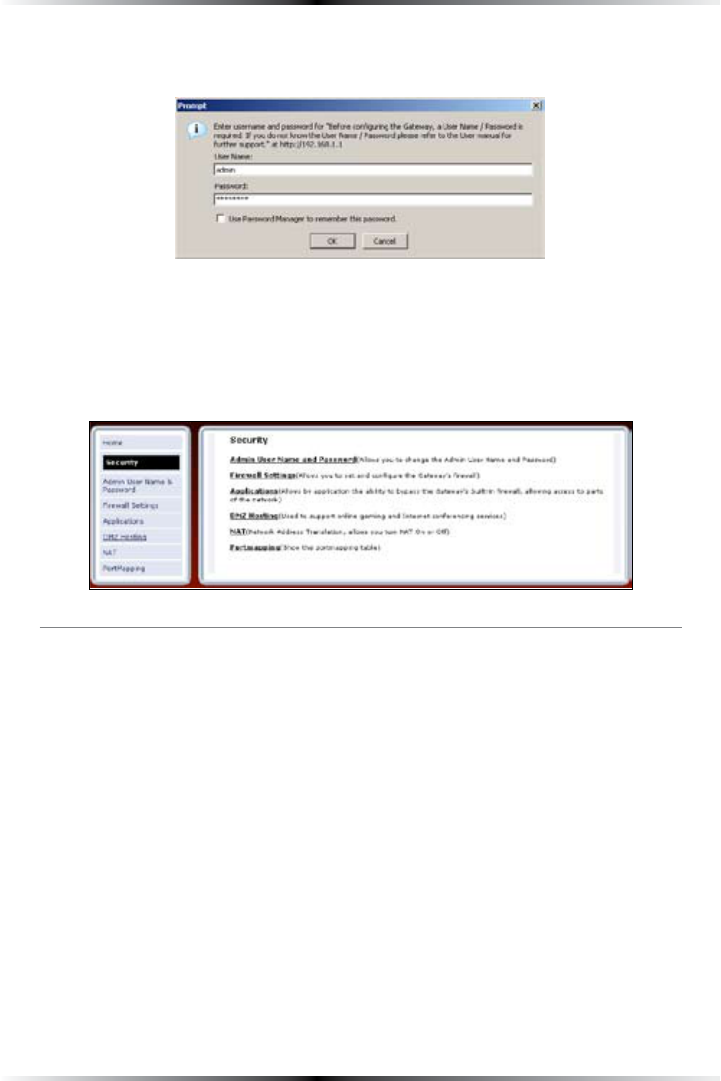
3. !LOGINWINDOWAPPEARS%NTERTHEUSERNAMEANDPASSWORDINTHEAPPROPRI-
ate text boxes, then click OK.
! Note: 4HEDEFAULTUSERNAMEIShADMINv4HEDEFAULTPASSWORDIS
hPASSWORDv
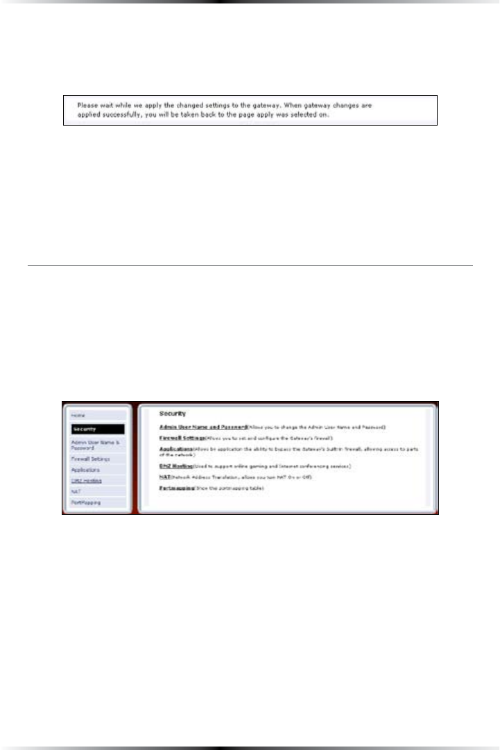
4. 4HEh3ECURITYvSCREENAPPEARS4OMODIFYASPECIFICCONFIGURATIONCLICKONITS
name in the menu bar on the left, or from the list in the middle of the screen.
Admin User Name and Password
3EEh#HANGINGTHE0ASSWORDvONPAGE
49
Chapter 6 Configuring Security Settings
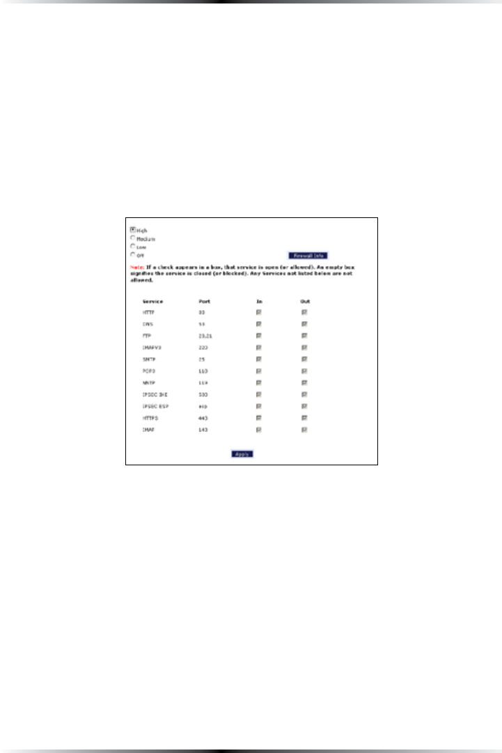
Firewall
Selecting Firewall in the Security screen generates the “&IREWALL3ETTINGSvSCREEN
Select the level of security needed for the network.
High
If High ISSELECTEDINTHEh&IREWALL3ECURITY,EVELvSCREENTHESERVICESLISTEDATTHEBOT-
tom of the screen (HTTP, DNS, &40, )-!0v, SMTP, 0/0, NNTP, )03%#)+%, )03%#
ESP, HTTPS, and )-!0ARETHEONLYONESALLOWEDTOPASSTHROUGHTHEFIREWALL!LL
other services will be blocked. None of these settings can be changed from here.
50
Wireless DSL Gateway User Manual
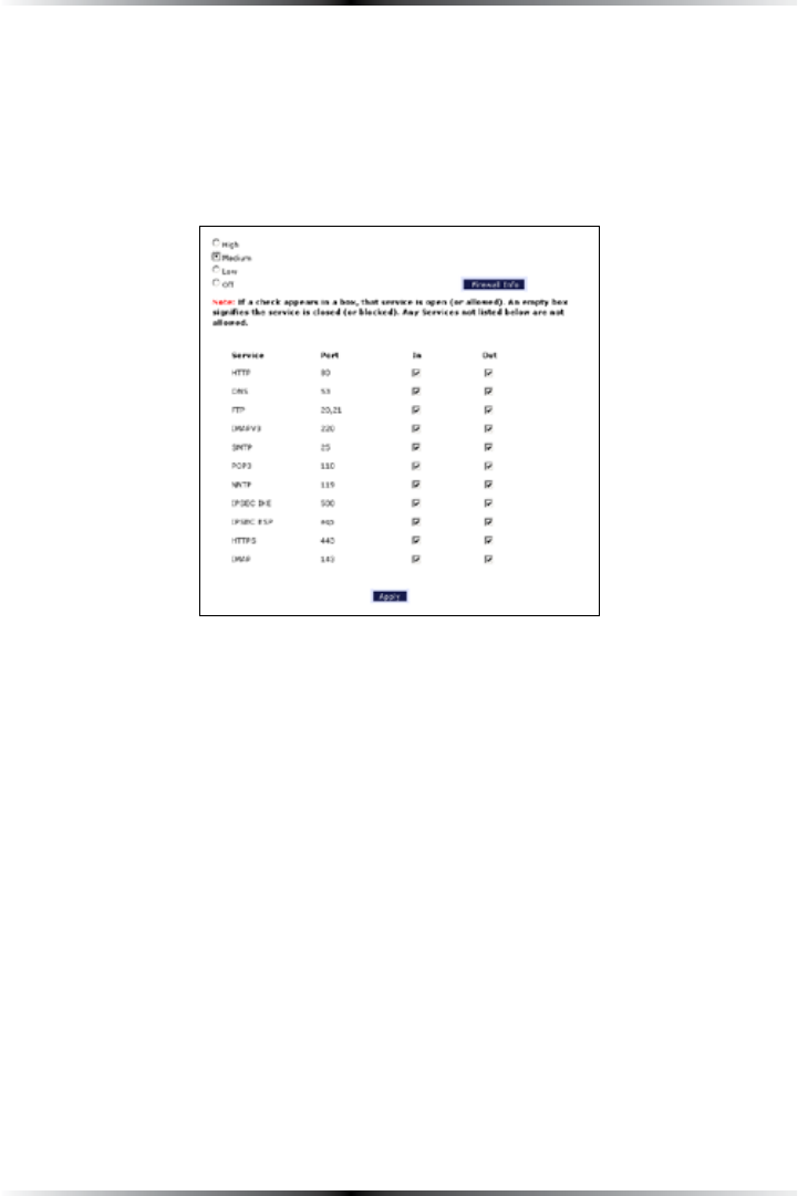
Medium
If Medium ISSELECTEDINTHEh&IREWALL3ECURITY,EVELvSCREENTHESERVICESLISTEDAT
the bottom of the screen (HTTP, DNS, &40, )-!0v, SMTP, 0/0, NNTP, )03%#)+%,
)03%#%30, HTTPS, and )-!0) are the only ones allowed to pass through the firewall.
!LLOTHERSERVICESWILLBEBLOCKED4HESESETTINGSCANBEMODIFIEDTOCUSTOMIZETHE
firewall settings.
When finished with this screen, click Apply to save the changes.
51
Chapter 6 Configuring Security Settings
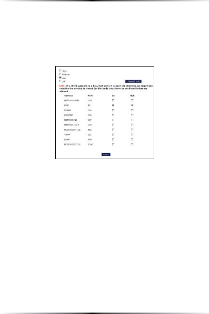
Low
If Low ISSELECTEDINTHEh&IREWALL3ECURITY,EVELvSCREENTHESERVICESLISTEDAT
the bottom of the screen (NETBIOS-SSN, DNS, %0-!0, 02/&),%, NETBIOS-NS,
NETBIOS-DGM, -)#2/3/&4$3, SNMP, ,$!0, and -)#2/3/&4'#,) can be
DENIEDACCESSTHROUGHTHEFIREWALL#LICKINTHEAPPROPRIATECHECKBOXTOALLOWOR
deny access for a particular service (check mark in the check box to deny; blank
CHECKBOXTOALLOW!LLSERVICESNOTLISTEDAREALLOWEDACCESS
Off
If Off ISSELECTEDINTHEh&IREWALL3ECURITY,EVELvSCREENFIREWALLFILTERINGISBASED
solely on the basic .!4 firewall.
! Note3EE!PPENDIX&h3ERVICE!CRONYMSvFORADESCRIPTIONOF
THESERVICESLISTEDINTHE&IREWALL3ECURITY,EVELSCREENS
52
Wireless DSL Gateway User Manual
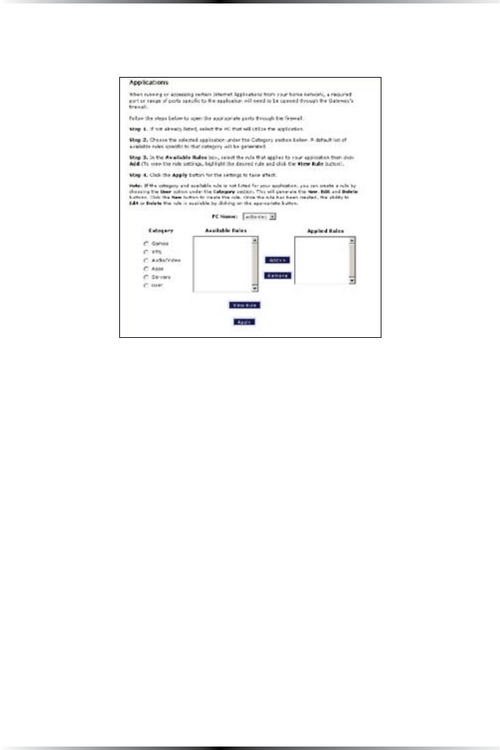
Applications
Selecting Applications in the Security screen generates the “!PPLICATIONSvSCREEN
This screen allows certain programs to bypass the Gateway’s built-in firewall,
allowing access to parts of the network (for hosting a Web or ftp server, for exam-
ple). To use, select the name of a computer on the network from the “0#.AMEv
drop-down list, then click Add.EXTSELECTAh#ATEGORYvBYCLICKINGTHEAPPROPRI-
ATERADIOBUTTON)NTHEh!VAILABLE2ULESvLISTBOXSELECTAGAMEAPPLICATIONSERVER
etc., then click Add>>4HESELECTEDITEMAPPEARSINTHEh!PPLIED2ULESvLISTBOX
Repeat for each item needed
4OREMOVEANITEMFROMTHE!PPLIED2ULESLISTHIGHLIGHTITTHENCLICKRemove.
To view an item’s rules (forwarded ports, etc.), highlight it, then click View Rule.
When finished with this screen, click Apply to save the changes.
53
Chapter 6 Configuring Security Settings
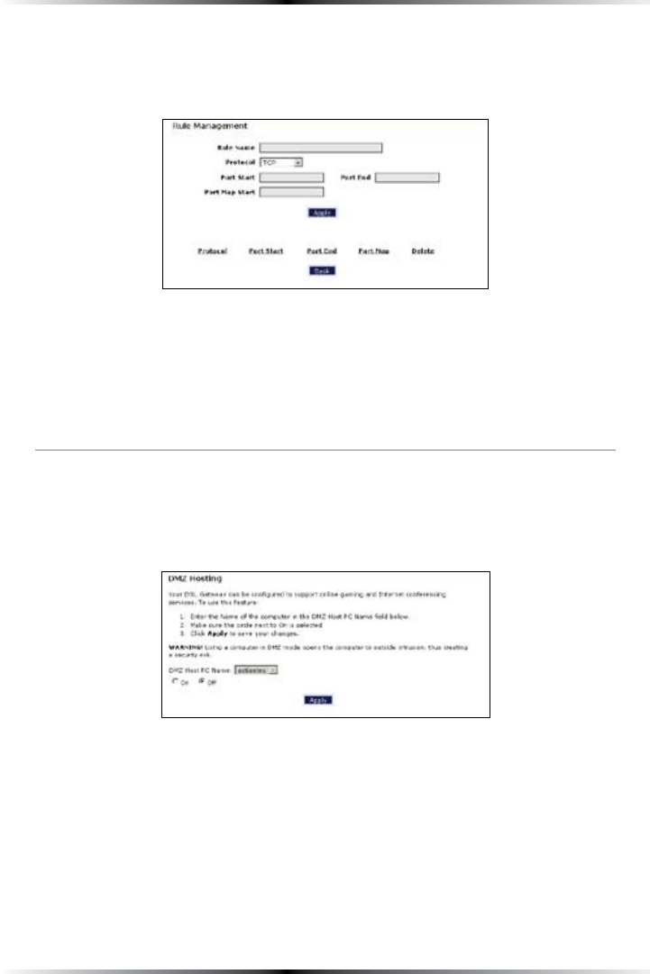
Rule Management
4OCREATEACUSTOMSETOFRULESCLICKTHEh5SERvRADIOBUTTONTHENCLICKNew. The
h2ULE-ANAGEMENTvSCREENAPPEARS
In this screen, the user can create a custom set of rules for a game or application
NOTLISTEDINTHE!PPLICATIONSSCREEN%NTERTHEh2ULE.AMEvh0ROTOCOLvh0ORT
3TARTvh0ORT%NDvANDh0ORT-APvINTHEAPPROPRIATETEXTBOXESTHENCLICKApply.
The rules are summarized at the bottom of the screen, and the rule set will appear
INTHE!PPLICATIONSSCREENAFTERCLICKINGBack.
DMZ Hosting
Selecting DMZ HostingINTHEh3ECURITYvSCREENGENERATESTHEhDMZ(OSTINGv
screen. To use DMZ hosting, select the computer on the network to be used as a
DMZ host in the “DMZ Host 0#.AMEvDROPDOWNMENUTHENCLICKOn.
DMZ hosting is used to support online gaming and Internet conferencing services.
These programs usually require multiple open ports, making the network acces-
sible from the Internet. DMZ hosting symbolically places the DMZ host computer
outside of the Gateway’s network. We recommend activating DMZ hosting only as
long as necessary.
When finished with this screen, click Apply to save the changes.
! Warning: The DMZ Host computer will be vulnerable to com-
puter hackers on the Internet while in DMZ mode.
54
Wireless DSL Gateway User Manual
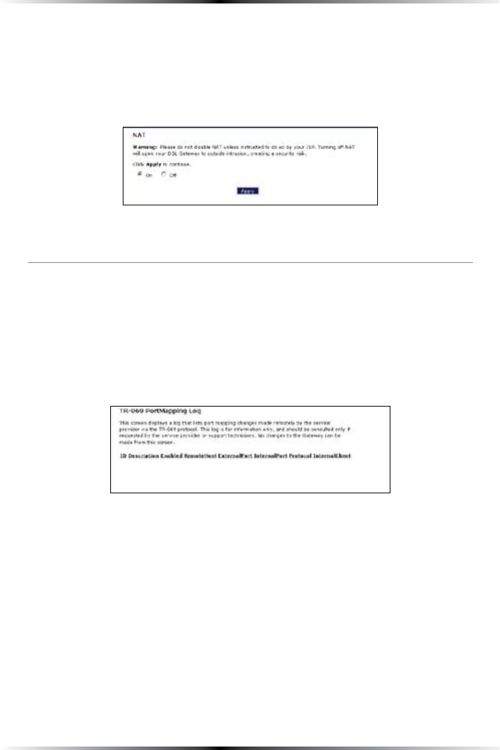
NAT (Network Address Translation)
Selecting NAT INTHEh3ECURITYvSCREENGENERATESTHEh.!4vSCREEN4HE'ATEWAYS
basic firewall security is based on .!4. Disabling .!4allows the computers con-
nected to the Gateway to be accessed by outside parties, and can cause the loss of
Internet connectivity. Do not turn .!4 off unless instructed to do so by Verizon.
When finished with this screen, click Apply to save the changes.
Port Mapping
Selecting Port Mapping INTHEh3ECURITYvSCREENGENERATESTHEh42
PortMapping LogvSCREEN4HISSCREENDISPLAYSALOGTHATLISTSPORTMAPPING
changes made remotely by the service provider via the TR-069 protocol. This log
is for information only, and should be consulted only if requested by the service
provider or support technicians. No changes to the Gateway can be made from
this screen.
55
#
Configuring
Parental Controls
This chapter explains how to configure the parental control capabilities of the
Gateway, such as services blocking, Web site blocking, and schedule rules.
Accessing Parental Control Screens
4OACCESSTHE0ARENTAL#ONTROLCONFIGURATIONSCREENSFOLLOWTHESEINSTRUCTIONS
1. /PENA7EBBROWSER)NTHEh!DDRESSvTEXTBOXTYPE
http://192.168.1.1
then press Enter on the keyboard.
2. 4HEh(OMEvSCREENAPPEARS#LICKParental Control.
7
56
Wireless DSL Gateway User Manual
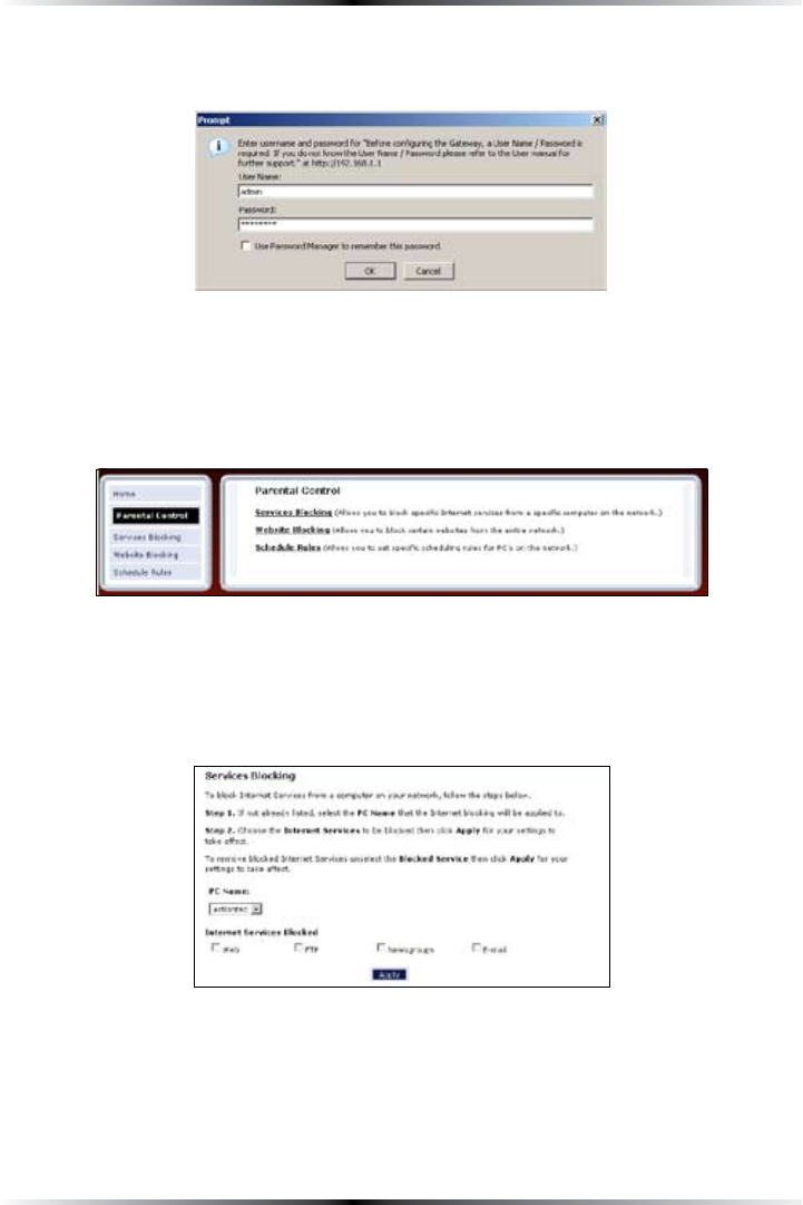
3. !LOGINWINDOWAPPEARS%NTERTHEUSERNAMEANDPASSWORDINTHEAPPROPRI-
ate text boxes, then click OK.
! Note: 4HEDEFAULTUSERNAMEIShADMINv4HEDEFAULTPASSWORDIS
hPASSWORDv
4. 4HEh0ARENTAL#ONTROLvSCREENAPPEARS4OMODIFYASPECIFICSETTINGCLICKONITS
name in the menu bar on the left, or from the list in the middle of the screen.
Services Blocking
Selecting Services BlockingINTHE0ARENTAL#ONTROLSCREENGENERATESTHEh3ERVICES
"LOCKINGvSCREEN
57
Chapter 7 Configuring Parental Controls
To modify Internet privileges (Web, &40, Newsgroups, etc.) for the computers on
the network:
1. 3ELECTTHECOMPUTERSNETWORKNAMEFROMTHEh0#.AMEvDROPDOWNMENU
2. Select the Internet service(s) to be blocked by clicking in the appropriate
check box.
3. #LICKApply to block the selected service from the selected computer.
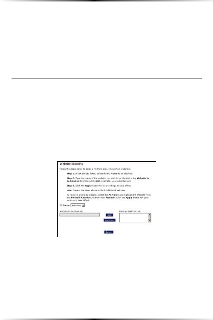
Website Blocking
Selecting Website BlockingINTHE0ARENTAL#ONTROLSCREENGENERATESTHEh7EBSITE
"LOCKINGvSCREEN4HISFEATUREENABLESTHE'ATEWAYTOBLOCK7EBSITESTOANYORALL
computers on the network. To block a Web site, select the computer name from
THEh0#.AMEvDROPDOWNMENU4HENENTERTHEADDRESSOFTHE7EBSITETOBE
blocked in the “7EBSITEv text box and click Add. The blocked Web site address will
BEDISPLAYEDINTHEh"LOCKED7EBSITE,ISTvTEXTBOXANDWILLNOTBEAVAILABLETOTHE
selected computer on the network. To block the Web site from another computer
on the network, repeat the process. To remove a blocked Web site, click on it in the
h"LOCKED7EBSITE,ISTvTHENCLICKRemove. When finished, click Apply.
58
Wireless DSL Gateway User Manual
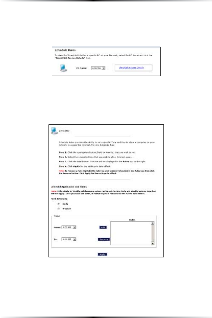
Schedule Rules
Selecting Schedule RulesINTHE0ARENTAL#ONTROLSCREENGENERATESTHEh3CHEDULE
2ULESvSCREEN3CHEDULERULESALLOWCOMPUTERSONTHENETWORKTOACCESSTHE
Internet at scheduled times only.
To set up schedule rules for a computer on the network:
1. 3ELECTTHECOMPUTERSNETWORKNAMEFROMTHEh0#.AMEvDROPDOWNMENU
2. #LICKView/Edit Access Details4HECOMPUTERSh!LLOWED!PPLICATIONAND
4IMESvSCREENAPPEARS
3. 4OSCHEDULE)NTERNETACCESSATTHESAMETIMEEVERYDAYSELECTh$AILYvBYCLICK-
ing the appropriate radio button. If creating different access schedules on a
DAYTODAYBASISSELECTh7EEKLYv
59
Chapter 7 Configuring Parental Controls
4a. )Fh$AILYvWASSELECTEDINSTEPCREATEAPERIODOF)NTERNETACCESSORRULE
BYSELECTINGABEGINNINGTIMEFROMTHEh&ROMvDROPDOWNMENUANDEND-
INGTIMEFROMTHEh4OvDROPDOWNMENU)FALLOWING)NTERNETACCESSTOA
PARTICULARCOMPUTERFROMPMTOPMFOREXAMPLESELECThPMv
FROMTHE&ROMDROPDOWNMENUANDhPMvFROMTHE4ODROPDOWN
MENU#LICKAdd TOADDTHEACCESSPERIODTOTHEh2ULESvLISTBOX!DDITIONAL
access periods can be added by repeating this step (9 a.m. through 12 p.m., for
example), and adding it to the Rules list box. Once the rules are applied in the
Daily screen, Internet access will be granted every day at the times listed in the
Rules list box.
! Note: 7HENUSINGh$AILYvSCHEDULINGANACCESSPERIODCAN-
not include 12 a.m (midnight). To create an access period that
includes midnight, create two access periods, one that ends at 12
a.m., and one that begins at 12 a.m.
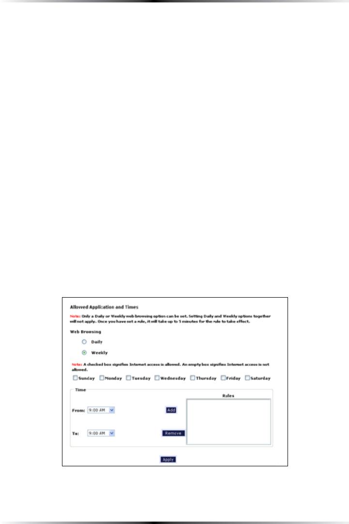
4b. )Fh7EEKLYvWASSELECTEDINSTEPPERIODSOF)NTERNETACCESSCANBESCHEDULED
ATDIFFERENTTIMESONDIFFERENTDAYSPMTOPMON&RIDAYANDPM
to 4 p.m. on Saturday, for example). To do this, select the day of the week by
clicking in the appropriate check box, then create a access period (or rule), as
EXPLAINEDINSTEPA#LICKAdd FOREACHSEPARATETIMEPERIOD!LLACCESSPERI-
ods created will appear in the Rules list box. Once the rules are applied in the
Weekly screen, Internet access will be granted to a particular computer at the
days and times selected on a weekly basis.

60
Wireless DSL Gateway User Manual
! Note: 7HENUSINGh7EEKLYvSCHEDULINGANACCESSPERIODCANNOT
include 12 a.m (midnight). To create an access period that includes
midnight, create two access periods, one that ends at 12 a.m. on
one day, and one that begins at 12 a.m on the following day.
5. When finished with all scheduling, click Apply to save the changes to the
Gateway.
Removing a Schedule Rule
To remove a scheduled rule, select it from the Rules list box, then click Remove.
The schedule rule will disappear from the Rules list box.
61
Configuring the
Gateway’s Utilities
This chapter explains how to use the Gateway’s utilities, including how to restore
default settings, upgrade the Gateway’s firmware, and perform a ping test.
Accessing the Utilities Screens
To access the Utilities configuration screens, follow these instructions:
1. /PENA7EBBROWSER)NTHEh!DDRESSvTEXTBOXTYPE
http://192.168.1.1
then press Enter on the keyboard.
2. 4HEh(OMEvSCREENAPPEARS#LICKUtilities.
8
62
Wireless DSL Gateway User Manual
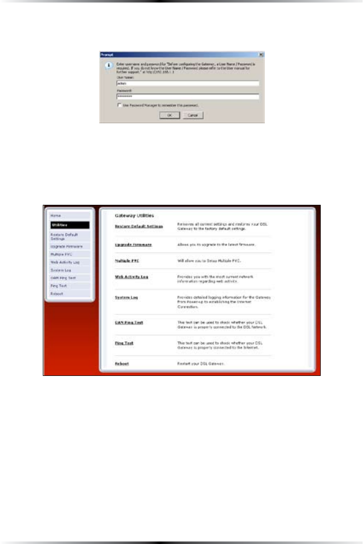
3. !LOGINWINDOWAPPEARS%NTERTHEUSERNAMEANDPASSWORDINTHEAPPROPRI-
ate text boxes, then click OK.
! Note: 4HEDEFAULTUSERNAMEIShADMINv4HEDEFAULTPASSWORDIS
hPASSWORDv
4. 4HEh5TILITIESvSCREENAPPEARS4OMODIFYASPECIFICCONFIGURATIONCLICKONITS
name in the menu bar on the left, or from the list in the middle of the screen.
63
Chapter 8 Configuring the Gateway’s Utilities
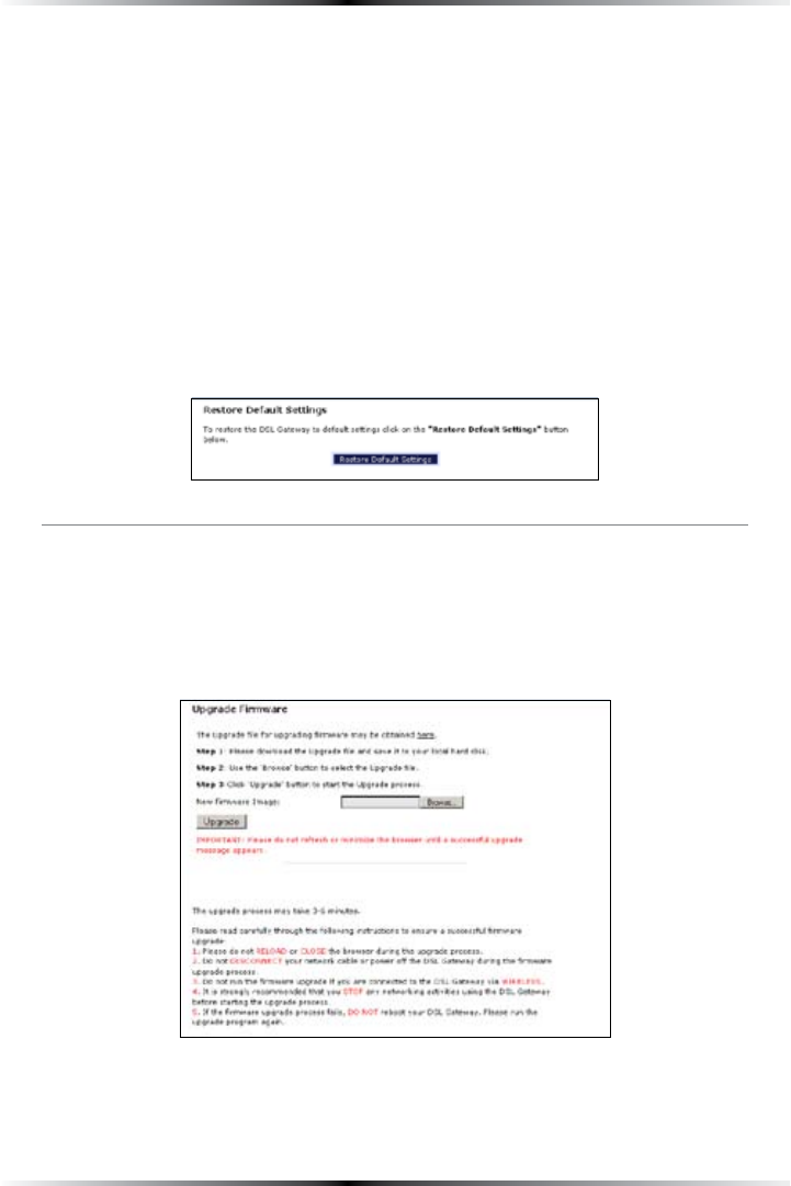
Restore Default Settings
To restore the Gateway to its factory default settings, select Restore Default Settings
FROMTHE5TILITIESSCREEN7HENTHEh2ESTORE$EFAULT3ETTINGSvSCREENAPPEARSCLICK
Restore Default Settings!NYCHANGESMADETOTHE'ATEWAYSSETTINGSWILLBELOST
and the factory default settings restored. During this process, the Gateway’s Power
light flashes and the Gateway is disabled.
" Warning: Do not unplug the Power cord from the Gateway
during the Restore Default Settings process. Doing so may result
in permanent damage to the Gateway.
When the Power Light stops flashing and glows steadily green, the Gateway is fully
operational.
Upgrade Firmware
Selecting Upgrade Firmware in the Utilities screen generates the “Upgrade
&IRMWAREvSCREEN&IRMWAREUPGRADESAREPERIODICALLYRELEASEDTOENHANCETHE
'ATEWAYSCAPABILITIES&OLLOWTHEINSTRUCTIONSONSCREENTOUPGRADETHE'ATEWAYS
firmware.
64
Wireless DSL Gateway User Manual
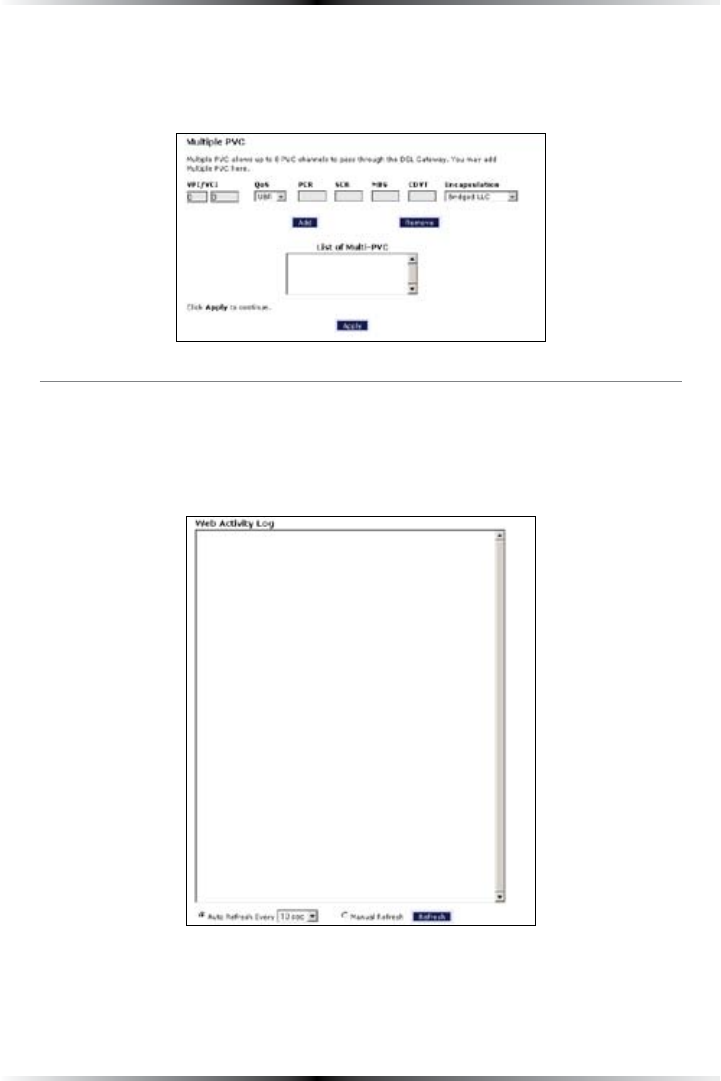
Multiple PVC
Selecting Multiple PVC in the Utilities screen generates the “Multiple 06#vSCREEN
which allows the configuration of multiple 06#s.
Web Activity Log
4HE7EB!CTIVITY,OGPROVIDESINFORMATIONABOUTTHE7EBSITESEACHCOMPUTER
ONTHE'ATEWAYSNETWORKHASVISITED4OACCESSTHE7EB!CTIVITY,OGSELECTWeb
Activity Log from the Utilities screen.
65
Chapter 8 Configuring the Gateway’s Utilities
Auto Refresh
4OSETTHE7EB!CTIVITY,OGSCREENTOAUTOMATICALLYREFRESHATCERTAININTERVALSACTI-
VATETHECIRCLENEXTTOh!UTO2EFRESH%VERYvATTHEBOTTOMOFTHE7EB!CTIVITY,OG
screen, then enter a time value (in seconds) in the text box, or click on the down
ARROWANDSELECTATIMEVALUEFROMTHEMENUTHATAPPEARS4HE7EB!CTIVITY,OG
will refresh at the selected interval.
Manual Refresh
4OSETTHE7EB!CTIVITY,OGSCREENTOMANUALLYREFRESHACTIVATETHECIRCLENEXTTO
h-ANUAL2EFRESHvATTHEBOTTOMOFTHE7EB!CTIVITY,OGSCREEN4OREFRESHTHE7EB
!CTIVITY,OGSCREENCLICKRefresh.
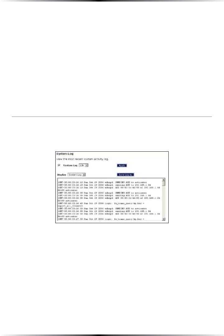
System Log
The System Log provides information about the Gateway’s activity. To access the
System Log, select System Log from the Utilities screen.
System Log (Size)
Select the size of the system log displayed here. The smaller the size, the shorter the
length of the system log saved.
Display
View other saved logs by selecting a log from this drop-down list.
66
Wireless DSL Gateway User Manual
Apply
Pressing this button saves any changes to the System Log screen and causes the
Save and Restart screen to appear.
Save Log As
Pressing this button allows the user to save a log as a file.
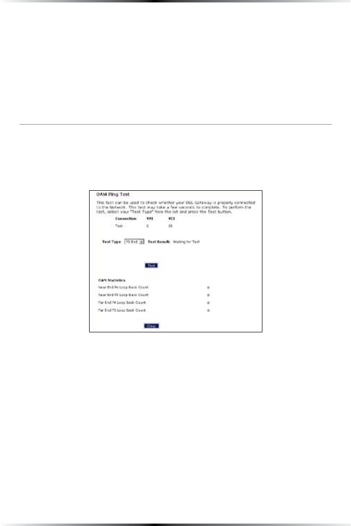
OAM Ping Test
Selecting OAM Ping Test from the Utilities screen generates the “/!-0ING4ESTv
screen, which is used to check whether the Gateway is properly connected to the
NETWORK&OLLOWTHEONSCREENINSTRUCTIONSTOPERFORMTHETEST
67
Chapter 8 Configuring the Gateway’s Utilities
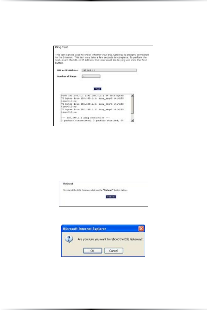
Ping Test
Selecting Ping TestFROMTHE5TILITIESSCREENGENERATESTHEh0ING4ESTvSCREENWHICH
ISUSEDTOCHECKWHETHERTHE'ATEWAYISPROPERLYCONNECTEDTOTHE)NTERNET&OLLOW
the on-screen instructions to perform the test.
Reboot
Selecting RebootFROMTHE5TILITIESSCREENGENERATESTHEh2EBOOTvSCREEN&ROMTHIS
screen, the Gateway can be rebooted. To do this:
1. &ROMTHEFIRST2EBOOTSCREENCLICKReboot.
2. !CONFIRMATIONWINDOWAPPEARS#LICKOK.

68
Wireless DSL Gateway User Manual
3. The Gateway reboots. Read the onscreen information in the screen that
appears.
When the Gateway’s Power light stops flashing, the Gateway has rebooted.

69
Specifications
General
Model Number
GT704-WG (Wireless DSL Gateway)
Standards
IEEE (10BaseT)
)%%%u (100BaseTX)
IEEE 802.11g (Wireless)
G.dmt
G.lite
t
2&#, , 2516
Protocol
LAN - #3-!/#$
WAN - PPP, $(#0, Static IP
WAN
&ULLRATE!$3,Interface
LAN
10/100 RJ-45 switched port
USB port
Speed
LAN Ethernet: 10/100 Mbps auto-sensing
Wireless: 802.11g 54 -BPSOPTIMALSEEh7IRELESS/PERATING2ANGEvFORDETAILS
Cabling Type
Ethernet 10BaseT: UTP/STP #ATEGORYor 5
Ethernet100BaseTX: UTP/STP #ATEGORY5
USB

70
Wireless DSL Gateway User Manual
Wireless Operating Range
Indoors
Up to 91M (300 ft.) @ 54 Mbps
Outdoors
Up to 457M (1500 ft.) @ 54Mbps
Topology
Star (Ethernet)
LED Indicators
Power, DSL, Internet, Ethernet (4), USB, Wireless
Environmental
Power
External, 12V DC, 1A
Certifications
FCC Class B, FCC Class C (part 15, 68), CE Mark Commercial, UL
Operating Temperature
0º C to 40º C (32ºF to 104ºF)
Storage Temperature
-20ºC to 70ºC (-4ºF to 158ºF)
Operating Humidity
10% to 85% non-condensing
Storage Humidity
5% to 90% non-condensing

71
Regulatory and
Compliance Notices
Important Safety Instructions
When using telephone equipment, basic safety precautions should always be fol-
lowed to reduce the risk of fire, electrical shock, and personal injury, including
the following:
s $ONOTUSETHISPRODUCTNEARWATERnFOREXAMPLENEARABATHTUBKITCHEN
sink, laundry tub, or swimming pool, or in a wet basement;
s !VOIDUSINGATELEPHONEOTHERTHANACORDLESSTYPEDURINGANELECTRICAL
storm, as there may be a remote risk of electrical shock due to lightning;
s $ONOTUSETHETELEPHONETOREPORTAGASLEAKINTHEVICINITYOFTHELEAK
s 5SEONLYTHEPOWERCORDANDBATTERIESINDICATEDINTHISMANUAL
s $ONOTDISPOSEOFBATTERIESINFIREASTHEYMAYEXPLODEnCHECKWITHLOCAL
codes for possible special disposal instructions.
Telephone Line Cord Caution
To reduce the risk of fire, use only No. 26 !7'ORLARGEREG!7'5,,ISTED
or #3!#ERTIFIED4ELECOMMUNICATION,INE#ORD
Class B Equipment
This equipment has been tested and found to comply with the limits for a Class B
DIGITALDEVICEPURSUANTTO0ARTOFTHEFCC Rules. These limits are designed to
PROVIDEREASONABLEPROTECTIONAGAINSTHARMFULINTERFERENCEINARESIDENTIALINSTALLA-
tion. This equipment generates, uses, and can radiate radio frequency energy and,
if not installed and used in accordance with the instructions, may cause harmful
INTERFERENCETORADIOCOMMUNICATIONS(OWEVERTHEREISNOGUARANTEETHATINTER-
ference will not occur in a particular installation. If this equipment does cause
HARMFULINTERFERENCETORADIOORTELEVISIONRECEPTIONWHICHCANBEDETERMINED
by turning the equipment off and on, the user is encouraged to try to correct the
interference by implementing one or more of the following measures:

72
Wireless DSL Gateway User Manual
s 2EORIENTORRELOCATETHERECEIVINGANTENNA
s )NCREASETHESEPARATIONBETWEENTHEEQUIPMENTANDRECEIVER
s #ONNECTTHEEQUIPMENTTOANOUTLETONACIRCUITDIFFERENTFROMTHATTO
WHICHTHERECEIVERISCONNECTED
s #ONSULTTHEDEALERORANEXPERIENCEDRADIOORTELEVISIONTECHNICIANFORHELP
Modifications
The FCC requires the user to be notified that any changes or modifications made
TOTHISDEVICETHATARENOTEXPRESSLYAPPROVEDBY!CTIONTECElectronics, Inc., may
VOIDTHEUSERSAUTHORITYTOOPERATETHEEQUIPMENT
$ECLARATIONOFCONFORMITYFORPRODUCTSMARKEDWITHTHEFCC LOGOn
5NITED3TATESONLY
4HISDEVICECOMPLIESWITH0ARTOFTHEFCC Rules. Operation is subject to the
following two conditions:
1 4HISDEVICEMAYNOTCAUSEHARMFULINTERFERENCE
2. 4HISDEVICEMUSTACCEPTANYINTERFERENCERECEIVEDINCLUDINGINTERFERENCETHAT
may cause unwanted operation.
Important Note
This equipment complies with FCC radiation EXPOSURELIMITSSETFORTHFORAN
UNCONTROLLEDENVIRONMENT4HISEQUIPMENTSHOULDBEINSTALLEDANDOPERATEDWITH
minimum distance 20 cm between the radiotor and your body.
The tramsmitter must not be co-located or operating in conjunction with any
other antenna or transmitter.
For questions regarding your product or the FCC declaration, contact:
!CTIONTECElectronics, Inc.
.ORTH-ARY!VE
3UNNYVALE#!
5NITED3TATES
4EL
&AX