Actiontec Electronics WCB5000 11ac Wireless Ethernet Bridge User Manual wcb5000 ncs um
Actiontec Electronics Inc 11ac Wireless Ethernet Bridge wcb5000 ncs um
Manual

802.11ac
MoCA 2.0
User Guide
Wireless
Ethernet Bridge
Model # WCB5000
0535-00xx-000 rev. 1

Table of Contents
Table of Contents 1
Introduction 3
Features 4
Getting to Know the Extender 5
Front Panel 5
Back Panel 6
Installing the Extender 7
Syncing Wi-Fi 7
Connecting the Extender 8
Accessing the Extender’s GUI 10
Status 13
Wireless Setup 14
Advanced Setup 20
1

WCB5000 Wireless Network Extender
Specications 23
Notices 25
Warranty 25
Important Safety Instructions 26
FCC Class B Equipment 27
Important Note on WiFi 28
2
Introduction
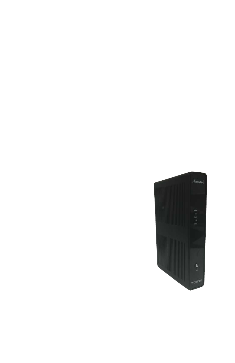
e Actiontec WCB5000 is a wireless network extender with dual
concurrent radios supporting both 2.4GHz and 5GHz operation in
802.11 a/b/g/n, and also 5GHz in 802.11ac. is allows the Extender to
connect to everything from legacy wireless laptops, computers, and
gaming platforms, up to the most current (and future) Apple and
Android tablets, laptops, media platforms, and smartphones.
e Extender works by being placed in a central location of the home, or
in a location where the existing wireless signal is weak, and then being
physically connected directly to your gateway/modem. is
physical connection not only extends the signal, but
allows the Extender to import and automatically
congure itself with the same network ID/SSID
and password currently in use and congured
on the existing gateway/modem. is means
that wherever you are in your house, your WiFi
tablet, laptop, phone, or wireless device will
automatically connect to Internet without
anyone having to nd a new network name or
enter security keys.
For users with newer mobile devices, tablets, and
laptops, connections through the 5GHz radio
can markedly increase the performance and
speed of your WiFi connection, while freeing up
the 2.4GHz band for legacy or older devices.
!
!
3

WCB5000 Wireless Network Extender
Features
• 2.4GHz and 5GHz dual concurrent 802.11 a/b/g/n WiFi radios
• 5GHz 802.11ac WiFi radio
• Four Gigabit Ethernet ports
• One coaxial port (MoCA 2.0)
• Integrated wireless networking with 2x2 802.11n and 2x2 802.11ac
access point
• Multiple security oerings, including, MAC address ltering, and
WPA
• Other options including WMM, IP address management, carrier
remote support and management, and upgradable rmware.
!
4
Getting to Know the Extender
is chapter describes the location and uses of the Extender’s LEDs,
ports, and buttons.
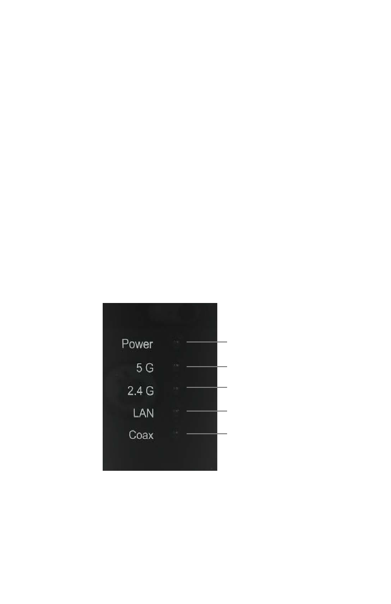
Front Panel
e front panel features LEDs that illuminate green when power, available
ports, and/or wireless bands are functioning and in use.
!
5
Power
2.4GHz radio
LAN
Coax
5GHz radio

WCB5000 Wireless Network Extender
Back Panel
•Power port: used to connect the power adapter (external, 12V DC,
1.5A, made by Ktec, model #KSASB0241200150HU) to the Extender.
•Reset button: restores the Extender back to the original factory default
settings when held down for at least 10 seconds.
•Coax port: used for connecting the Extender to a coaxial network.
•Four-port Gigabit Ethernet switch: used for directly connecting the
Extender to the gateway/modem or other Ethernet devices.
•Labels: indicate the factory default GUI access username and
password, network SSID names, and security keys.
!
!
6

Installing the Extender
ere are two parts to installing an Extender: syncing the Wi-Fi settings,
and placing and connecting the Extender.
Syncing Wi-Fi
To sync the Extender with the gateway/modem’s Wi-Fi settings:
1. Place the Extender next to the gateway/modem.
2. Plug the Extender’s power adapter into the Power port of the
Extender, and the other end into an electrical wall outlet.
3. Press the WPS button on both the Extender and the gateway/modem
simultaneously for ten seconds.
4. Make sure the WPS button on the Extender is glowing green. If the
WPS button glows red, try syncing the Wi-Fi settings again. e
Extender can also be manually congured to connect with the
gateway/modem’s wireless network (see “Wireless Setup” on !
page 14).
e Extender is now synced with the gateway/modem’s Wi-Fi settings.
Unplug the Extender and its power cable and continue on to the next
section of this chapter, “Connecting the Extender.”"
7
WCB5000 Wireless Network Extender
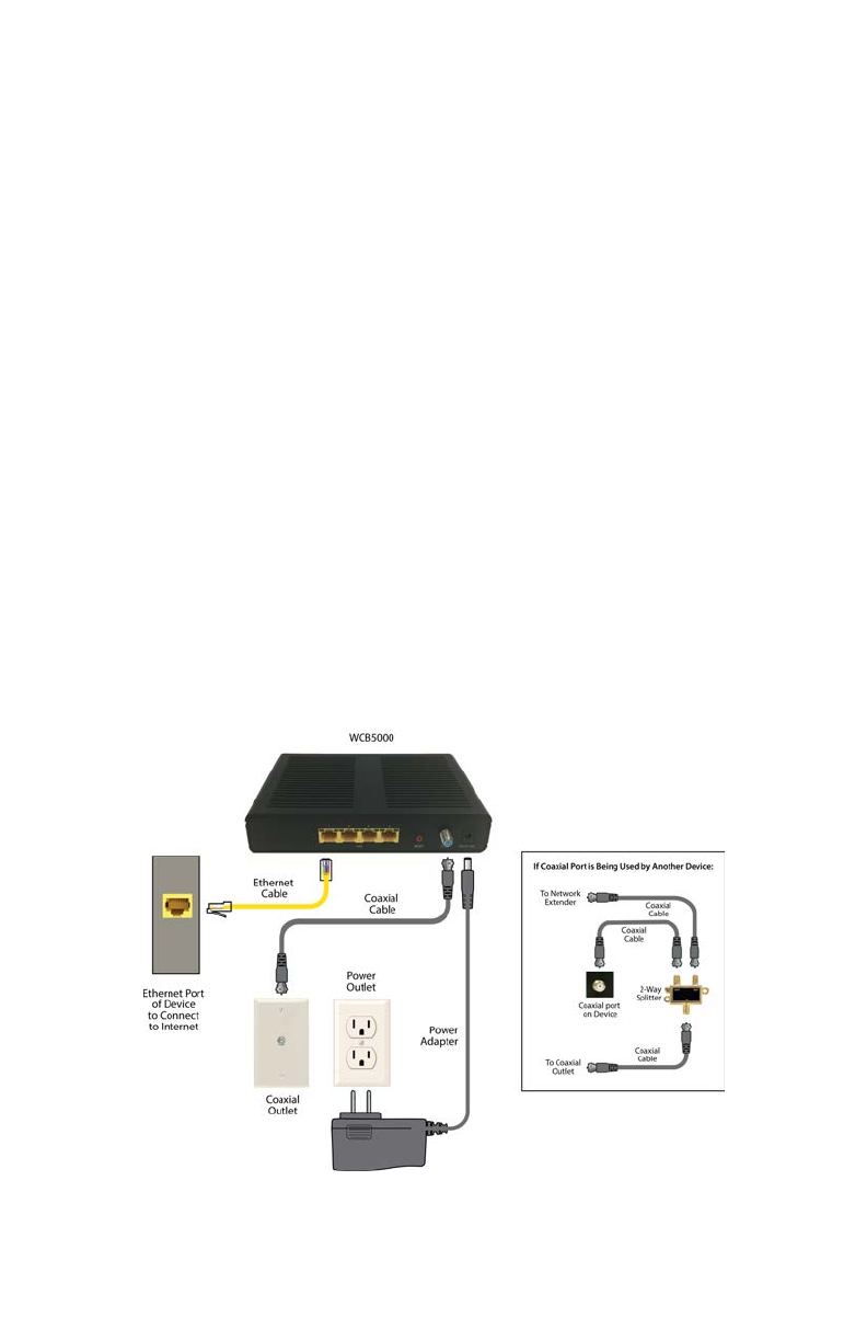
Connecting the Extender
Now that the Extender is synced with the gateway/modem’s wireless
network, it can be connected to the gateway/modem’s MoCA network
and placed in another area or room of the home/oce. To do this:
1. Place the Extender in an area where the Wi-Fi signal is weak or
spotty. A coaxial outlet must be available nearby.
2. Connect the included coaxial cable into the Coax port on the rear
panel of the Extender.
3. Connect the other end of the coaxial cable into the nearby coaxial
outlet.
4. Plug the Extender’s power adapter into the Power port of the
Extender, and the other end into an electrical wall outlet.
5. If applicable, connect an Ethernet cable between one of the Extender’s
LAN ports and the Ethernet port of a non-wireless device (wireless
devices will connect via the wireless network). e conguration
should look similar to the gure, below:
!
8

Installing the Extender
6. Wait until the Coax and Wireless LEDs on the front panel of the
Extender glow green. is may take a few minutes.
e Extender is now synced, installed, and extending the gateway/
modem’s wireless network in a previously weak area.
Using a Coaxial Splitter
If another device is using the coaxial outlet needed from step 3 in the
previous procedure, perform the following steps:
1. Disconnect the coaxial cable from the coaxial outlet.
2. Connect a coaxial cable between the coaxial outlet and the single port
on a two-way coaxial splitter.
3. Connect the coaxial cable disconnected in step 1of this procedure to
one of the dual ports on the splitter.
4. Connect a coaxial cable between the Coax port of the Extender and
the other dual port on the splitter.
e nal conguration should be similar to the inset in the gure on the
previous page.
!
9

Accessing the Extender’s GUI
e Extender features an onboard graphical user interface (GUI) that
includes user-congurable settings. Some of these settings should be
accessed by experienced network technicians only.
To congure the network settings of the Extender:
1. Ensure that the Extender is connected to a gateway/modem’s MoCA
coaxial network, and that both devices are powered on.
2. On a computer connected to the same network as the gateway/
modem and Extender, log in to the gateway/modem’s GUI. e IP
address for this log in will vary between dierent gateway/modems.
3. e gateway/modem’s GUI appears. Find the Extender by its MAC
ID from the list of connected devices or status screen. e MAC ID of
the Extender is provided on a sticker located on the rear panel of the
Extender.
4. Write down the IP address of the Extender.
5. Enter the IP address written down in step 4 in the address box of the
web browser."
10

Accessing the Extender’s GUI
!
6. e Extender’s Status screen appears. Enter the Extender’s Username
and Password (found on the label located on the back panel of the
Extender), in the User Name and Password text boxes in the upper
right corner of the Status screen.
!
11
WCB5000 Wireless Network Extender
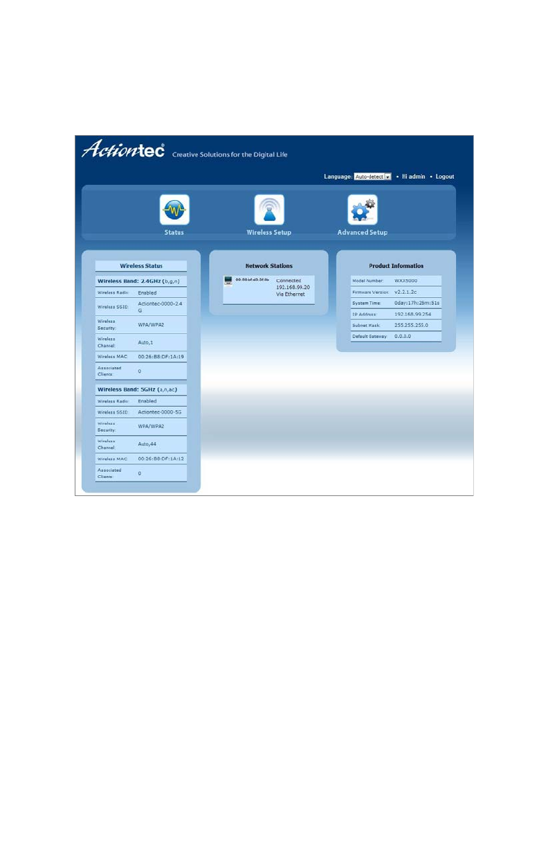
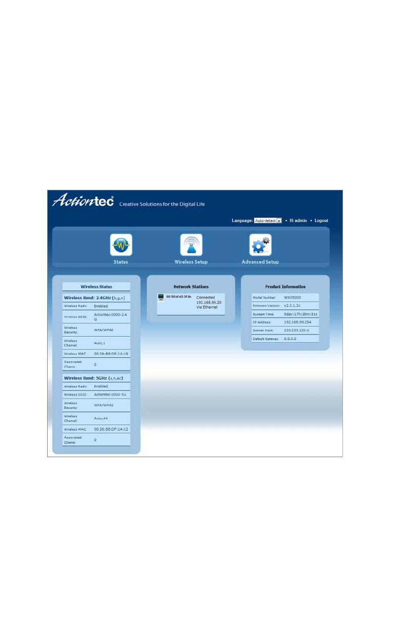
e Extender’s GUI’s Status screen appears, as shown below:
!
12
Accessing the Extender’s GUI
Status
e rst GUI screen that appears is the Status screen, which can also be
generated by clicking the Status icon in the menu bar. is screen
contains basic information about the Extender’s wireless status, network
stations, and product information about the Extender. ere are no
congurable settings available in this screen.
!
13
WCB5000 Wireless Network Extender
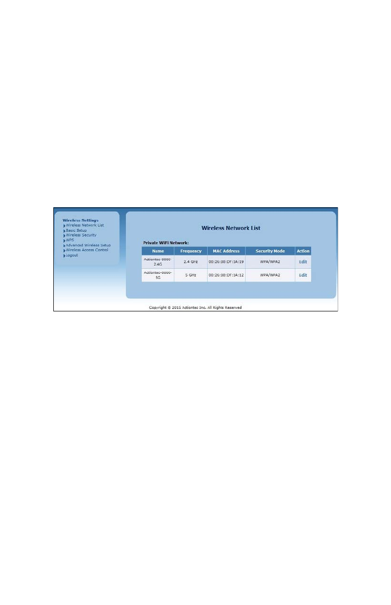
Wireless Setup
Clicking the Wireless Setup icon from the menu bar of any of the
Extender’s GUI screens generates the Wireless Network List screen.
Additional wireless settings can be accessed from the menu on the le
side. ese settings congure various aspects of the Extender’s wireless
network, and the majority of them should be adjusted by an experienced
network technician only. e exceptions are the settings contained in the
Basic Setup screen.
!
Wireless Network List
Selecting Wireless Network List generates the Wireless Network List
screen (above). is screen displays various characteristics of the
Extender’s wireless networks. !
14
Accessing the Extender’s GUI
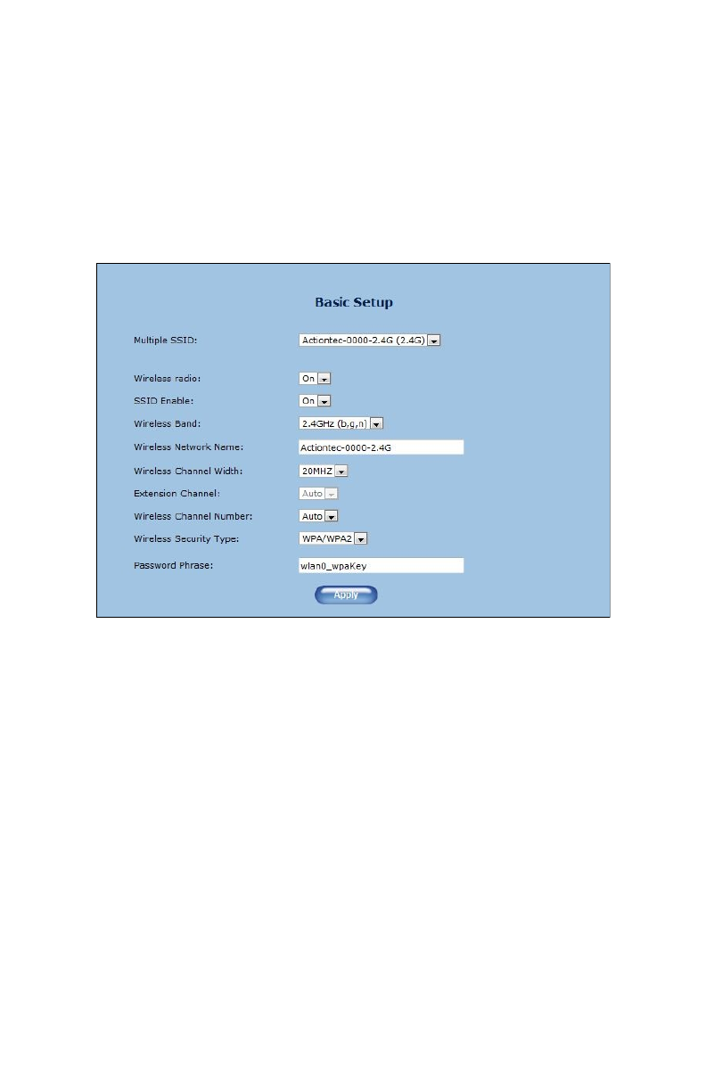
Basic Setup
e Basic Setup wireless network screen contains various settings
regarding the Extender’s wireless network. When nished adjusting the
settings in this screen, click Apply.
!
Multiple SSID
is option allows the user to setup dierent SSIDs (wireless
networks) with dierent parameters. Select the option desired from
the Multiple SSID drop-down menu.
Wireless Radio
is option turns the Extender’s wireless radio on and o.
SSID Enable
is option controls whether or not the name of the network is
broadcast to other wireless devices (usually, in the device’s available
15

WCB5000 Wireless Network Extender
wireless network list). Select Enable or Disable by clicking in the
appropriate radio button.
Wireless Band
is option allows the user to select the bandwidth at which the
Extender’s wireless radio will operate.
Wireless Network Name
Enter the name of the wireless network in this text box.
Wireless Channel Width
is option allows the user to select the channel width at which the
Extender’s wireless radio will operate. We recommend using the
default setting.
Extension Channel
is option allows the user to select the extension channel for the
Extender’s wireless radio. We recommend using the default setting.
Wireless Channel Number
is option allows the user to select the channel number at which the
Extender’s wireless radio will operate. We recommend leaving the
channel number as is. e Extender and gateway automatically scan
for the best channel at every boot up
Wireless Security Type
is option allows the user to select the type of security applied to the
Extender’s wireless network.
Password Phrase
is option allows the user to enter a custom password phrase or
value.
!
16
Accessing the Extender’s GUI
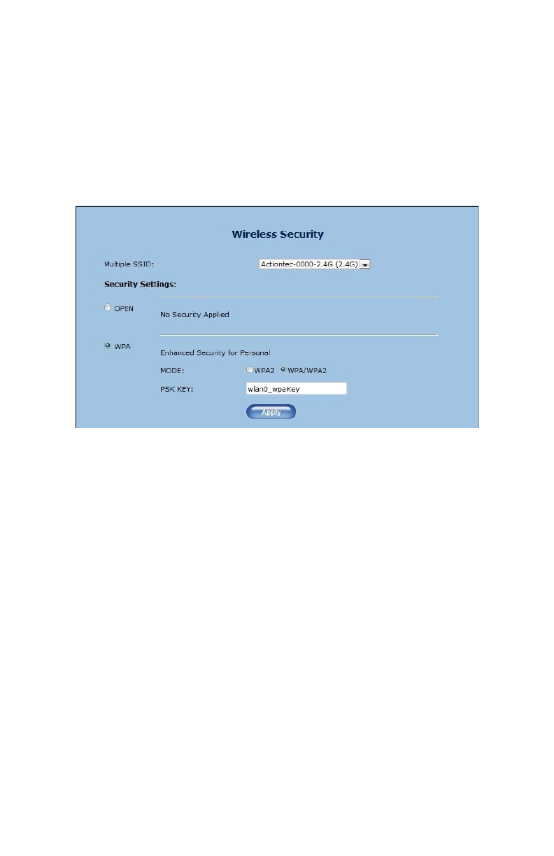
Wireless Security
e Wireless Security screen allows the user to apply wireless security to
the Extender’s wireless network. is screen should be accessed by
experienced network technicians only.
!
17
WCB5000 Wireless Network Extender
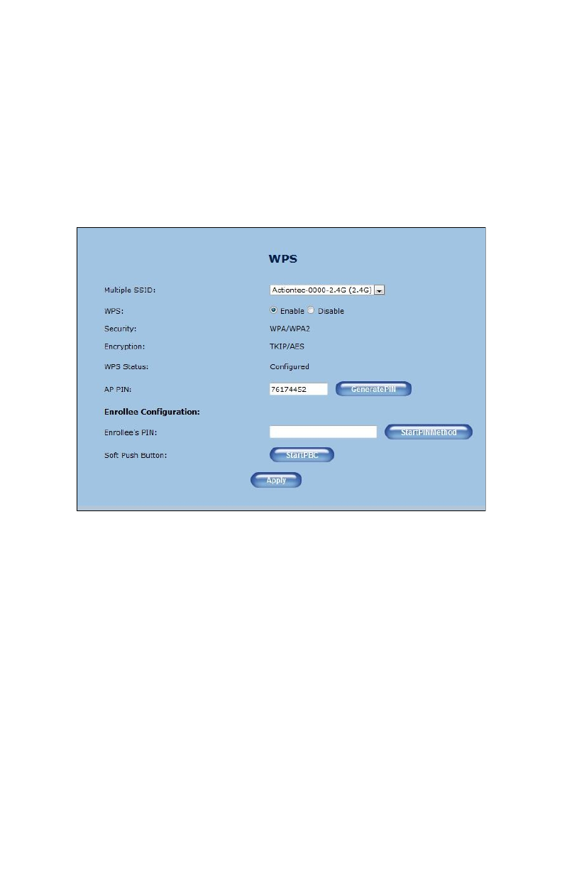
WPS
e WPS screen allows the Extender to accept wireless clients via Wi-Fi
Protected Setup (WPS), an automatic wireless network connection
protocol. Only experienced network technicians should congure the
settings in this screen.
!
18
Accessing the Extender’s GUI
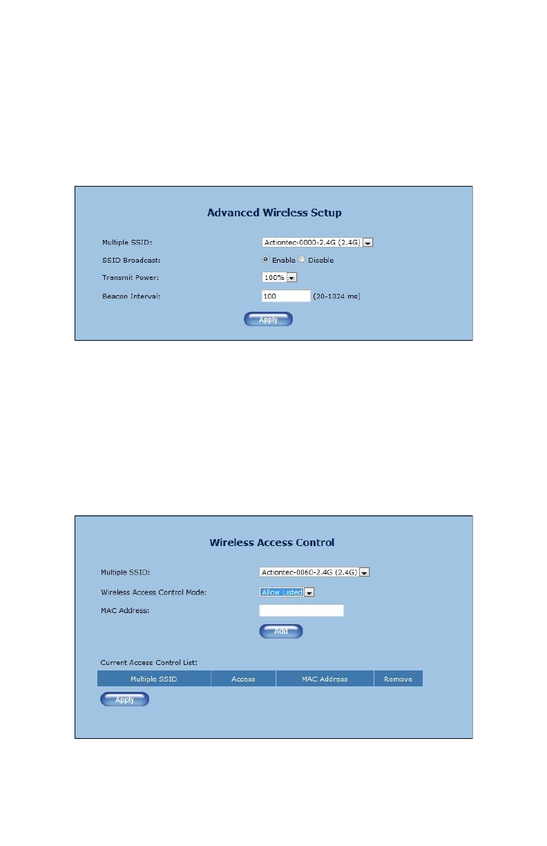
Advanced Wireless Setup
e Advanced Wireless Setup screen allows the Extender to be congured
with multiple SSIDs.
!
Wireless Access Control
e Wireless Access Control screen contains a number of advanced
settings regarding the Extender’s wireless network. Only experienced
network technicians should congure these settings.
!
19
WCB5000 Wireless Network Extender
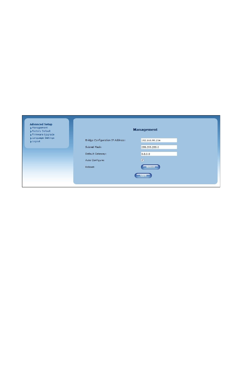
Advanced Setup
Clicking the Advanced Setup icon from any of the Extender’s GUI screens
generates the Management screen, along with other advanced settings
accessed through the menu on the le side. ese settings congure
various administrative aspects of the Extender and its GUI. ey should
be adjusted by an experienced network technicians only.
!
Management
e Management screen (above) allows the Extender’s IP address settings
to be modied. Only experienced network technicians should change
these settings. !
20
Accessing the Extender’s GUI
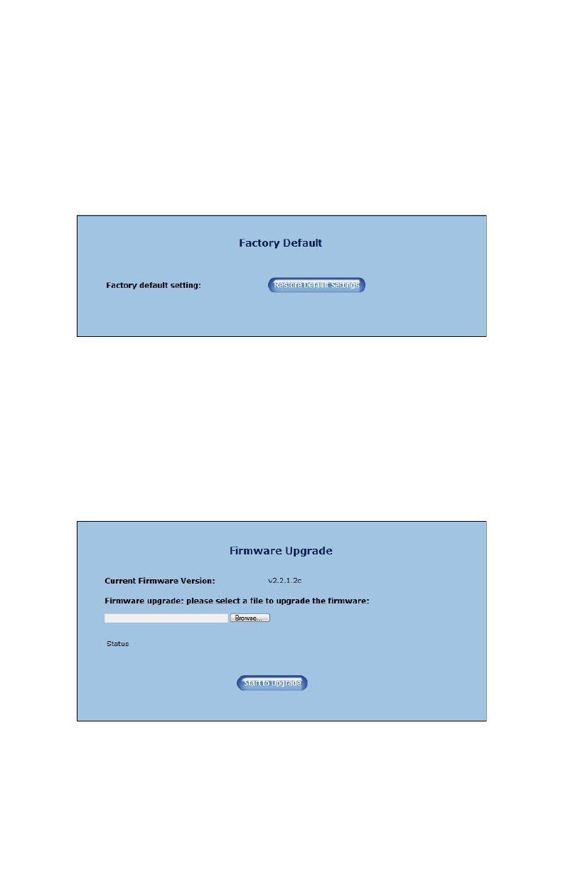
Factory Default
e Factory Default advanced setup screen allows the Extender’s factory
default settings to be reapplied, erasing all current settings. Click Restore
Default Settings to restore the Extender to its factory default state.
!
Factory Default
e Firmware Upgrade advanced setup screen allows the Extender’s
rmware to be upgraded. Once the upgrade le has been downloaded
and located, click Start to Upgrade.
21
WCB5000 Wireless Network Extender
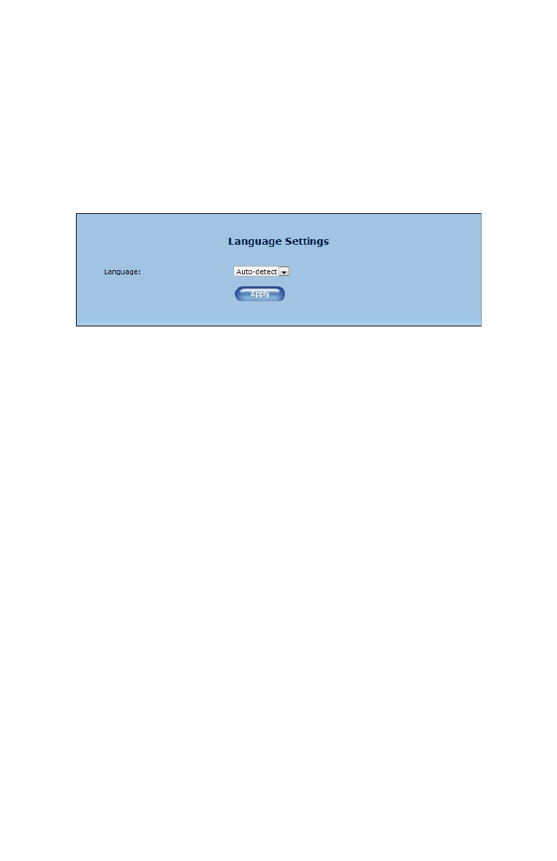
Language
e Language advanced setting screen allows the user to apply another
language to the Extender’s GUI. Select the language from the Language
drop-down menu, then click Apply.
!
!
22

Specications
Model Number
WCB5000
Wireless
Wi-Fi (a, b, g, n, ac)
WPA, WPA2
WMM
Wi-Fi Protected Setup
IP
Wi-Fi 802.11 a/b/g/n/ac IEEE standard 5GHz/2.4GHz
LAN Connections
Ethernet ports (4): 10/100/1000
Coaxial port (1): MoCA 2.0
LED Indicators
Power, WiFi 2.4 GHz, WiFi 5 GHz, LAN, Coax, WPS
Antennas
2x2: internal 2.4 GHz!
2x2: internal, 5 GHz
!
23

WCB5000 Wireless Network Extender
Power
External, 12V DC, 1.5A, made by Ktec, model #KSASB0241200150HU
Regulatory
FCC part 15B and 15C, UL
Environmental
Operating temperature - 0ºC to 40ºC (32ºF to 104ºF)
Storage temperature - 0ºC to 70ºC (32ºF to 158ºF)
Operating humidity - 10% to 85% non-condensing
Storage humidity - 5% to 95% non-condensing
Altitude: -197 . to 7000 .
Note: Specications are subject to change without notice.
!
!
24

Notices
Warranty
is product has a one-year Limited Hardware Warranty and 90-day free
soware updates from date of purchase.
Local Law
is Limited Warranty Statement gives the customer specic legal rights.
e customer may also have other rights which vary from state to state in
the United States, from province to province in Canada, and from
country to country elsewhere in the world.
To the extent that this Limited Warranty Statement is inconsistent with
local law, this Statement shall be deemed modied to be consistent with
such local law. Under such local law, certain disclaimers and limitations
of this Warranty Statement may not apply to the customer.
Go to http://www.actiontec.com/products/warranty.php for more
information.
!
25

WCB5000 Wireless Network Extender
Important Safety Instructions
is device is restricted to indoor operations only.
Basic safety precautions should always be followed to reduce the risk of
re, electrical shock, and personal injury, including the following:
• Do not use this product near water – for example, near a bathtub,
kitchen sink, laundry tub, or swimming pool, or in a wet basement;
only clean with dry cloth.
• Do not block any ventilation openings. Install in accordance with the
manufacturer's instructions. Do not install near any heat sources such
as radiators, heat registers, stoves, or other apparatus including
ampliers that produce heat.
• Do not use the telephone to report a gas leak in the vicinity of the
leak.
• Use only the power cord indicated in this manual if applicable.
Coaxial Cable
If applicable, the coaxial cable screen shield needs to be connected to the
Earth at the building entrance per ANSI/NFPA 70, the National Electrical
Code (NEC), in particular Section 820.93, “Grounding of Outer
Conductive Shield of a Coaxial Cable,” or in accordance with local
regulation"
26

Notices
FCC Class B Equipment
is equipment has been tested and found to comply with the limits for a
Class B digital device, pursuant to Part 15 of the FCC Rules. ese limits
are designed to provide reasonable protection against harmful
interference in a residential installation. is equipment generates, uses
and can radiate radio frequency energy and, if not installed and used in
accordance with the instructions, may cause harmful interference to radio
communications. However, there is no guarantee that interference will
not occur in a particular installation. If this equipment does cause
harmful interference to radio or television reception, which can be
determined by turning the equipment o and on, the user is encouraged
to try and correct the interference by implementing one or more of the
following measures:
• Reorient or relocate the device;
• Increase the separation between the equipment and receiver;
• Connect the equipment to an outlet on a circuit dierent from that to
which the receiver is connected (applicable only to powerline
products);
• Consult the dealer or an experience radio or television technician for
help.
Modications
e FCC requires the user to be notied that any changes or
modications made to this device that are not expressly approved by
Actiontec Electronics, Inc., may void the user’s authority to operate the
equipment.
27

WCB5000 Wireless Network Extender
Declaration of Conformity for Products Marked with
the FCC Logo
is device complies with Part 15 of the FCC Rules. Operation is subject
to the following two conditions:
1. is device may not cause harmful interference;
2. is device must accept any interference received, including
interference that may cause undesired operation of the device.
Important Note on WiFi
If applicable, this equipment complies with FCC radiation exposure limits
set forth for an uncontrolled environment.
e radio has been found to be compliant to the requirements set forth in
CFR 47 Sections 2.1091, 15.247 (b) (4),15.407 addressing RF Exposure
from radio frequency devices as dened in Evaluating Compliance with
FCC Guidelines for Human Exposure to Radio Frequency
Electromagnetic Fields. e equipment should be installed more than 30
cm (~12 in.) from your body or nearby persons.
Only channel 1~11 can be operated for the 2.4 GHz ISM band and
channels 36 to 48 and 149-165 for the UNII and ISM Bands. (Channels
52-64 and 100-144 are available if the device is enabled for DFS Band)
Channels 124-128 are currently permanently disabled for weather radar.
Selection of other channels is not possible.
28