Actiontec Electronics WCB5200 11ac Wireless Network Extender User Manual wcb5200 um
Actiontec Electronics Inc 11ac Wireless Network Extender wcb5200 um
UserManual.wiki
>
Actiontec Electronics
>
WCB5200 User Manual
>
User Manual pt 1
Contents
1.
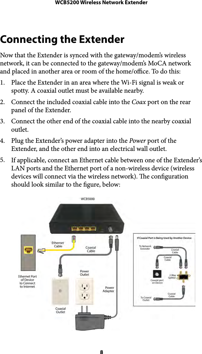
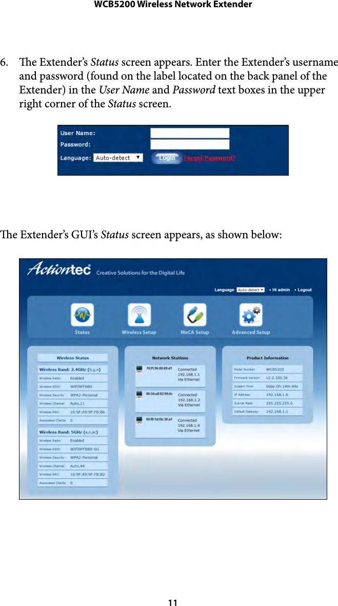
User Manual pt 1
2.
User Manual Pt 2
3.
User Manual pt 2
User Manual pt 1
Navigation menu
Upload a User Manual
Namespaces
Wiki Guide
HTML
PDF
Info
Views
User Manual
Discussion / Help
Navigation