Actiontec Electronics WXB6X40Q 802.11ac Wireless 4-Port Ethernet Bridge User Manual WxB6x40Q NCS UM 1US
Actiontec Electronics Inc 802.11ac Wireless 4-Port Ethernet Bridge WxB6x40Q NCS UM 1US
Contents
- 1. user Manual pt 1
- 2. User Manual pt 2
- 3. User Manual pt 1
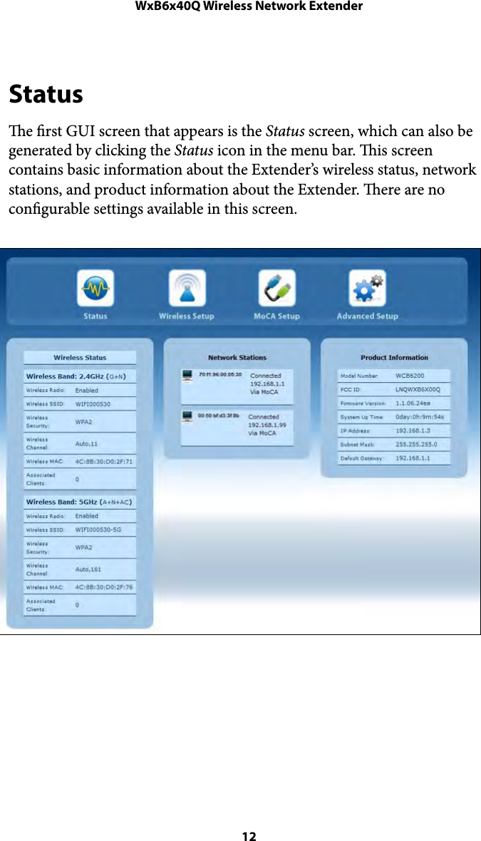
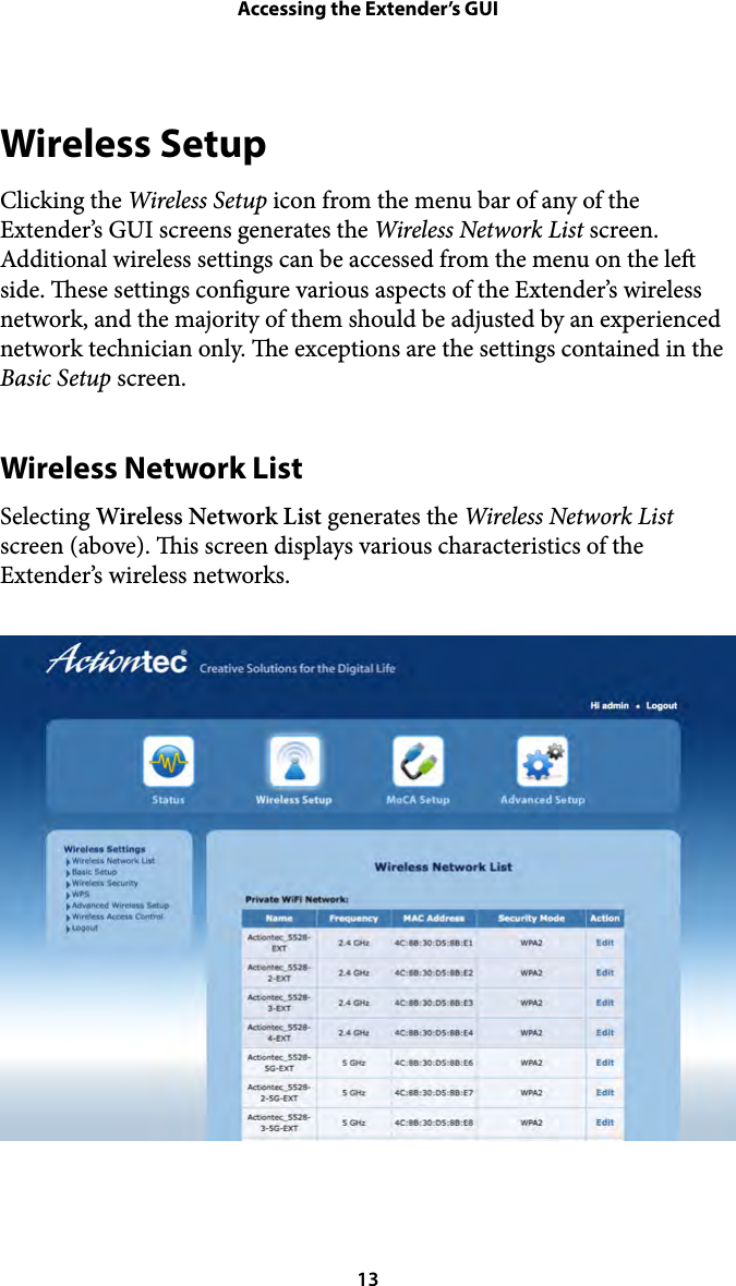
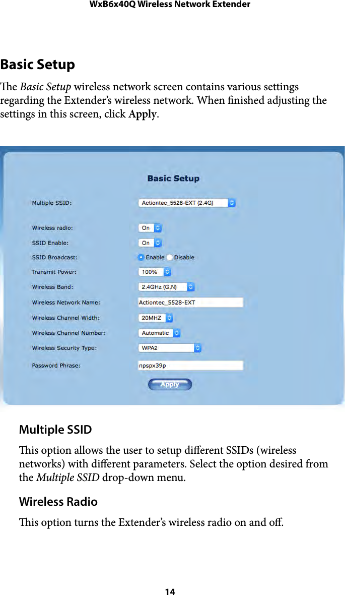
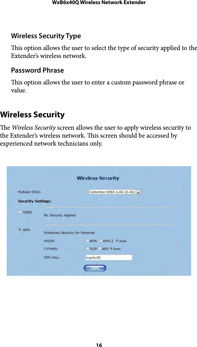
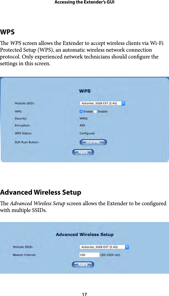
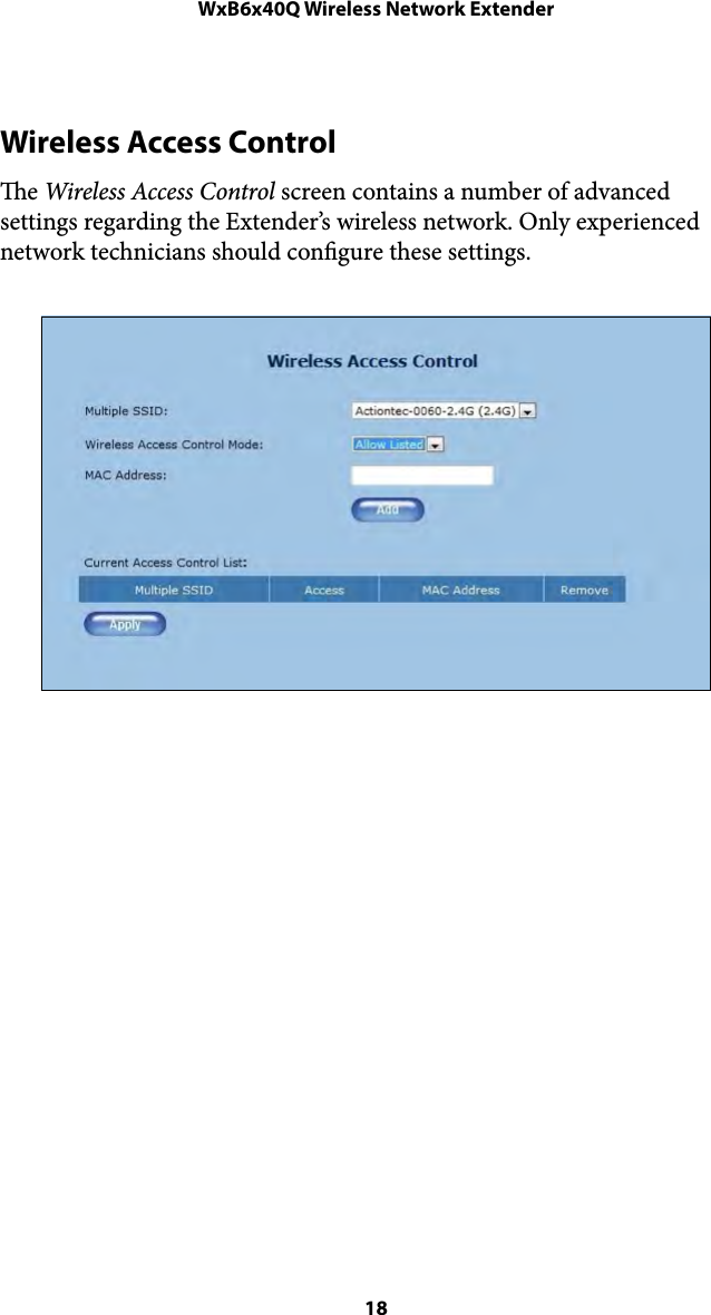
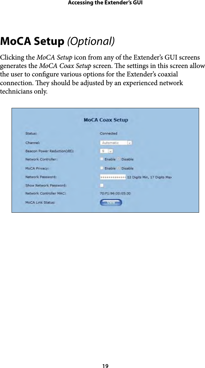
user Manual pt 1