Actwell Technology ACT-203TX Wireless Control Security/Alarm Transmitter Camera User Manual Part 2
Actwell Technology Inc. Wireless Control Security/Alarm Transmitter Camera Users Manual Part 2
Contents
- 1. Users Manual Part 1
- 2. Users Manual Part 2
Users Manual Part 2
MOUNTING OPTIONS
G",=-..
G, ~~
cfl
""IIJ
~',~ "
." . !
~ ' , "
.
'~
~".,:'
"V" -:'1'~
~ ,
"'~
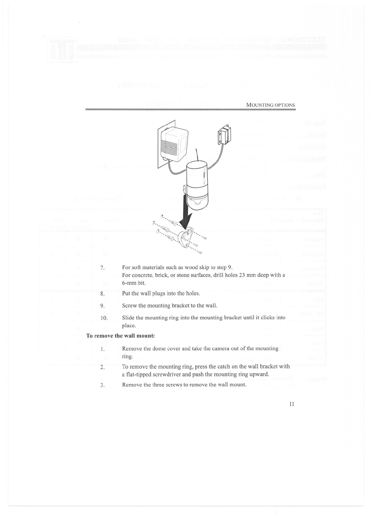
7. For soft materials such as wood skip to step 9.
For concrete, brick, or stone surfaces, drill holes 23 mm deep with a
6-mm bit.
Put the wall plugs into the holes.
8.
9. Screw the mounting bracket to the wall.
Slide the mounting ring into the mountingbracket until it clicks into
place.
To remove the wall mount:
10.
1. Remove the dome cover and take the camera out of the mounting
ring.
To remove the mounting ring, press the catch on the wall bracket with
a flat-tipped screwdriver and push the mounting ring upward.
2.
3. Remove the three screws to remove the wall mount.
II
2-SETTING UP
Hidden installation
The camera can be concealed in a variety of locations such as behind a thin partition
or inside a suitcase.
Note: Drill a 6.3mm diameter hole in the surface you want to mount the camera
behind. To prevent the camera view from being obscured, the surface
that the camera is behind must not exceed 3 mm in thickness.
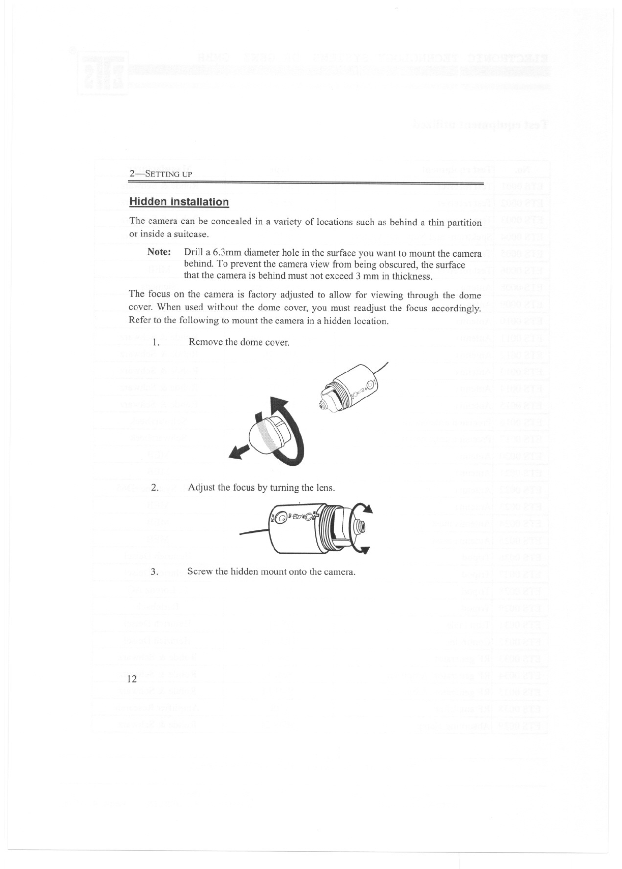
The focus on the camera is factory adjusted to allow for viewing through the dome
cover, When used without the dome cover, you must readjust the focus accordingly.
Refer to the following to mount the camera in a hidden location.
1. Remove the dome cover. ~("';
d . "".(::)
'£IT
2. Adjust the focus by turning the lens.
-(@'~1(qf
3. Screw the hidden mount onto the camera.
12
MOUNTING OPTIONS
~'~i(a) ..
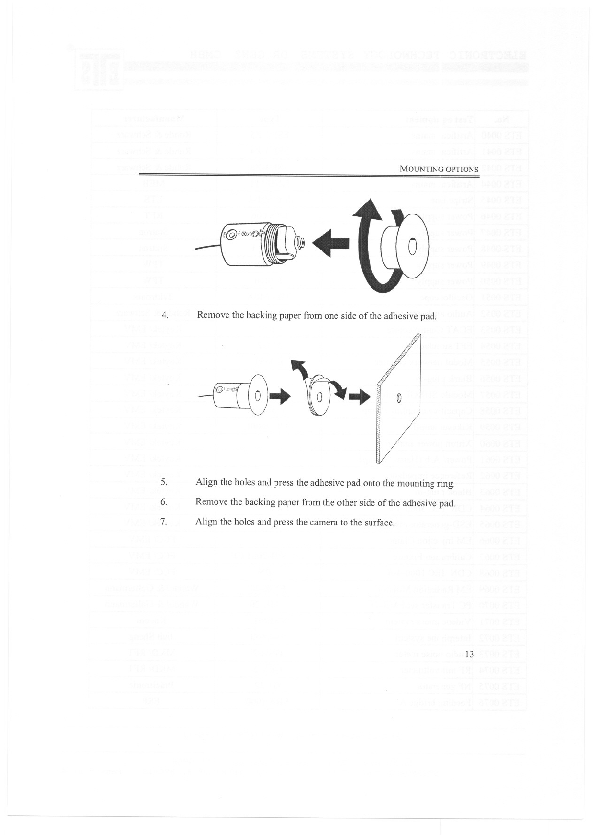
4. Remove the backing paper from one side of the adhesive pad.
~'.10"~.. @
5. Align the holes and press the adhesive pad onto the mounting ring.
6. Remove the backing paper from the other side of the adhesive pad.
7. Align the holes and press the camera to the surface.
13
2-SETTING UP
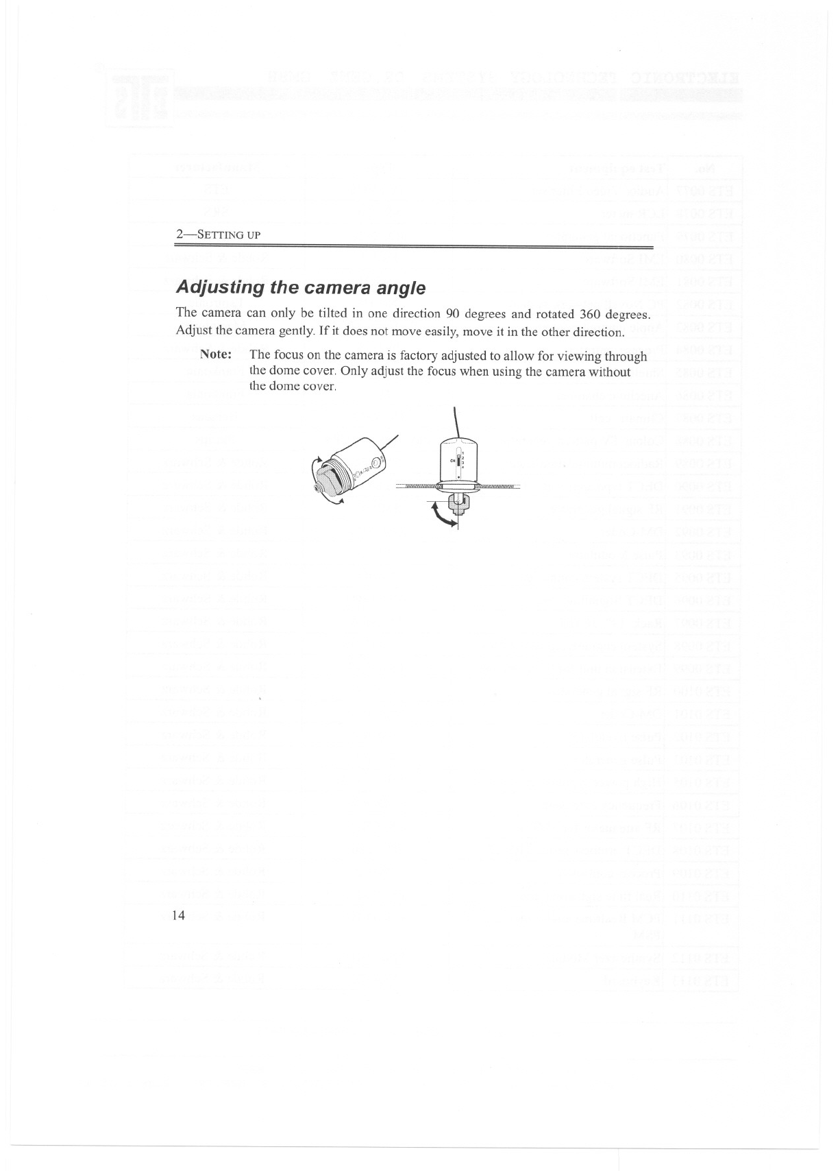
Adjusting the camera angle
The camera can only be tilted in one direction 90 degrees and rotated 360 degrees.
Adjust the camera gently. If it does not move easily, move it in the other direction.
Note: The focus on the camera is factory adjusted to allow for viewing through
the dome cover. Only adjust the focus when using the camera without
the dome cover.
14
3-0peration
The chapter describes the operation of the remote camera.
Operating restrictions
. Only use 9V batteries with the adapter.
.Avoid using the camera in humid locations. If condensation occurs, allow the
camera to dry before operating.
Do not use in temperatures below -10 degrees Celsius or above 55 degrees
Celsius.
.
.Proximity to microwave ovens can cause interference and reduce the quality
of the audio and video signals.
Using two cameras in the same vicinity may result in sound and picture
interference.
.
3-0PERATION
Matching channels
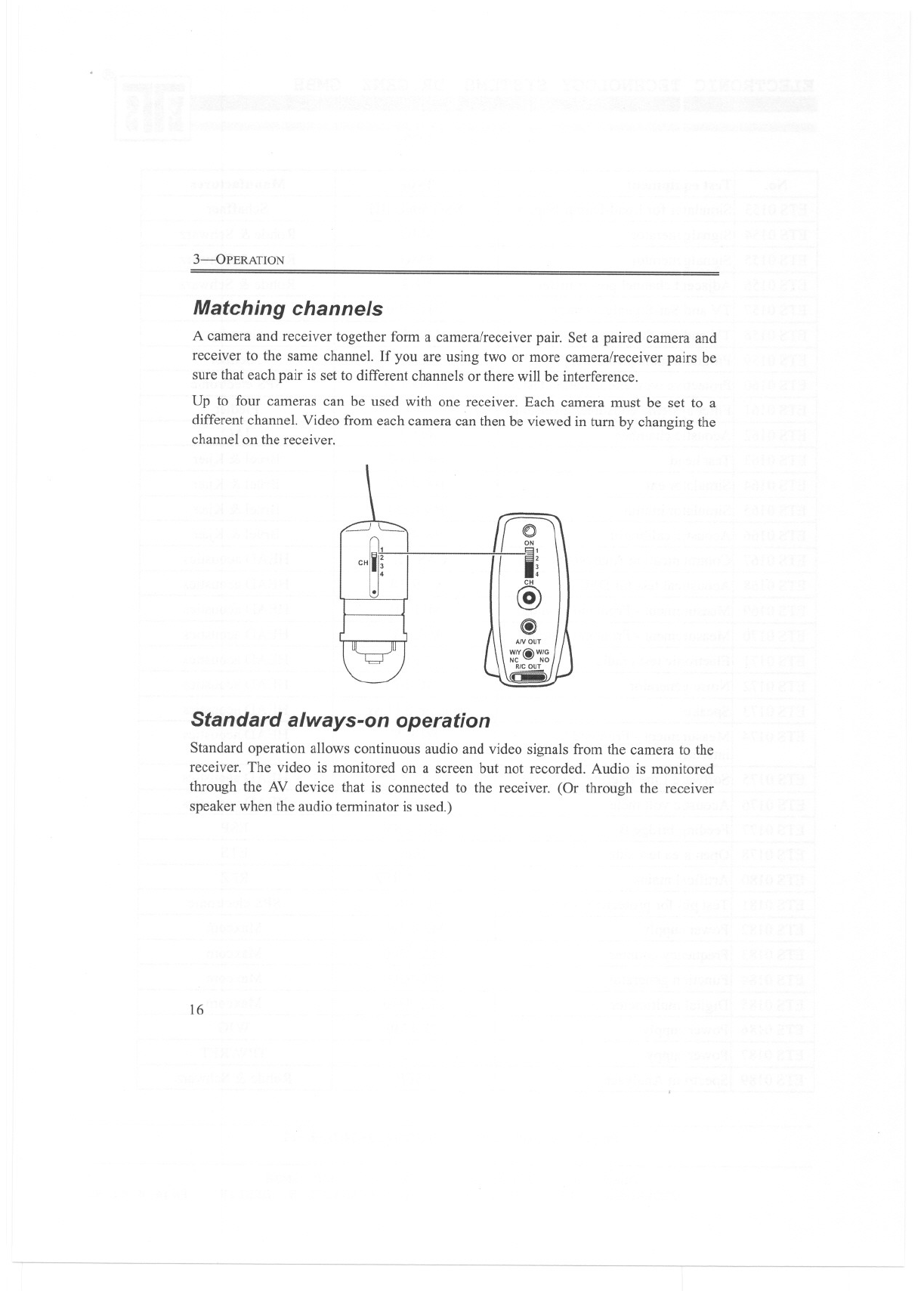
A camera and receiver together form a camera/receiver pair. Set a paired camera and
receiver to the same channel. If you are using two or more camera/receiver pairs be
sure that each pair is set to different channels or there will be interference.
Up to four cameras can be used with one receiver. Each camera must be set to a
different channel. Video from each camera can then be viewed in turn by changing the
channel on the receiver.
0
ON
-I;
@
@)
~
,"~j
Standard always-on operation
Standard operation allows continuous audio and video signals ITomthe camera to the
receiver. The video is monitored on a screen but not recorded. Audio is monitored
through the AV device that is connected to the receiver. (Or through the receiver
speaker when the audio terminator is used.)
16
REED SWITCH OPERATION
Reed switch operation
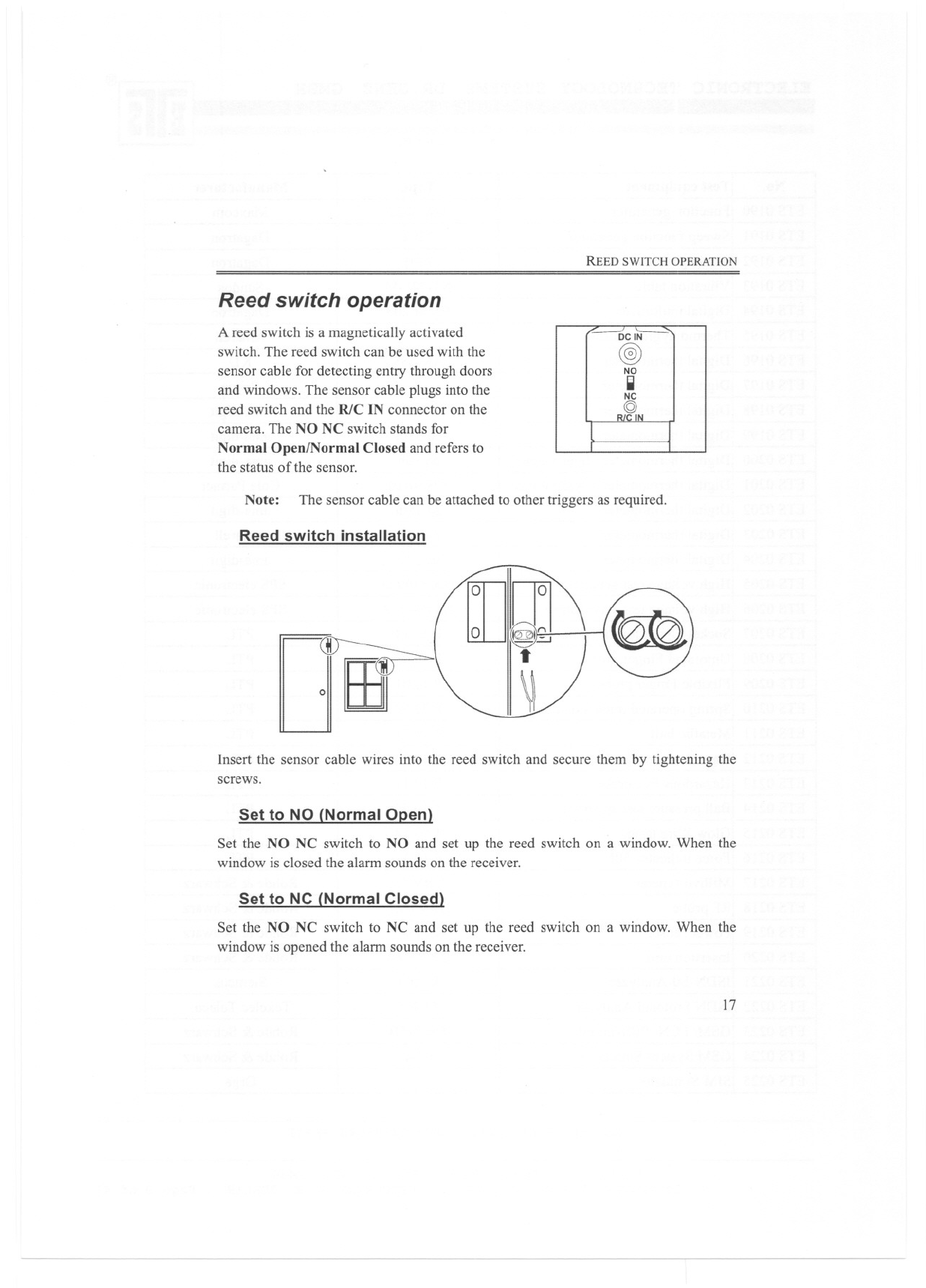
A reed switch is a magnetically activated
switch. The reed switch can be used with the
sensor cable for detecting entry through doors
and windows. The sensor cable plugs into the
reed switch and the RlC IN connector on the
camera. The NO NC switch stands for
Normal Open/Normal Closed and refers to
the status of the sensor.
DCIN
@)
NO
II
NC
Q)N
Note: The sensor cable can be attached to other triggers as required.
Reed switch installation
Insert the sensor cable wires into the reed switch and secure them by tightening the
screws.
Set to NO (Normal Open)
Set the NO NC switch to NO and set up the reed switch on a window. When the
window is closed the alarm sounds on the receiver.
Set to NC (Normal Closed)
Set the NO NC switch to NC and set up the reed switch on a window. When the
window is opened the alarm sounds on the receiver.
17
3--OPERATION
RIC cable operation
The R/Ccableis a relay connectingcable,whichallowsrecordingof audioandvideo
to be triggered by an alann such as the supplied reed switch. This function saves
recording space as recording only begins after an event such as a door opening or
closing.
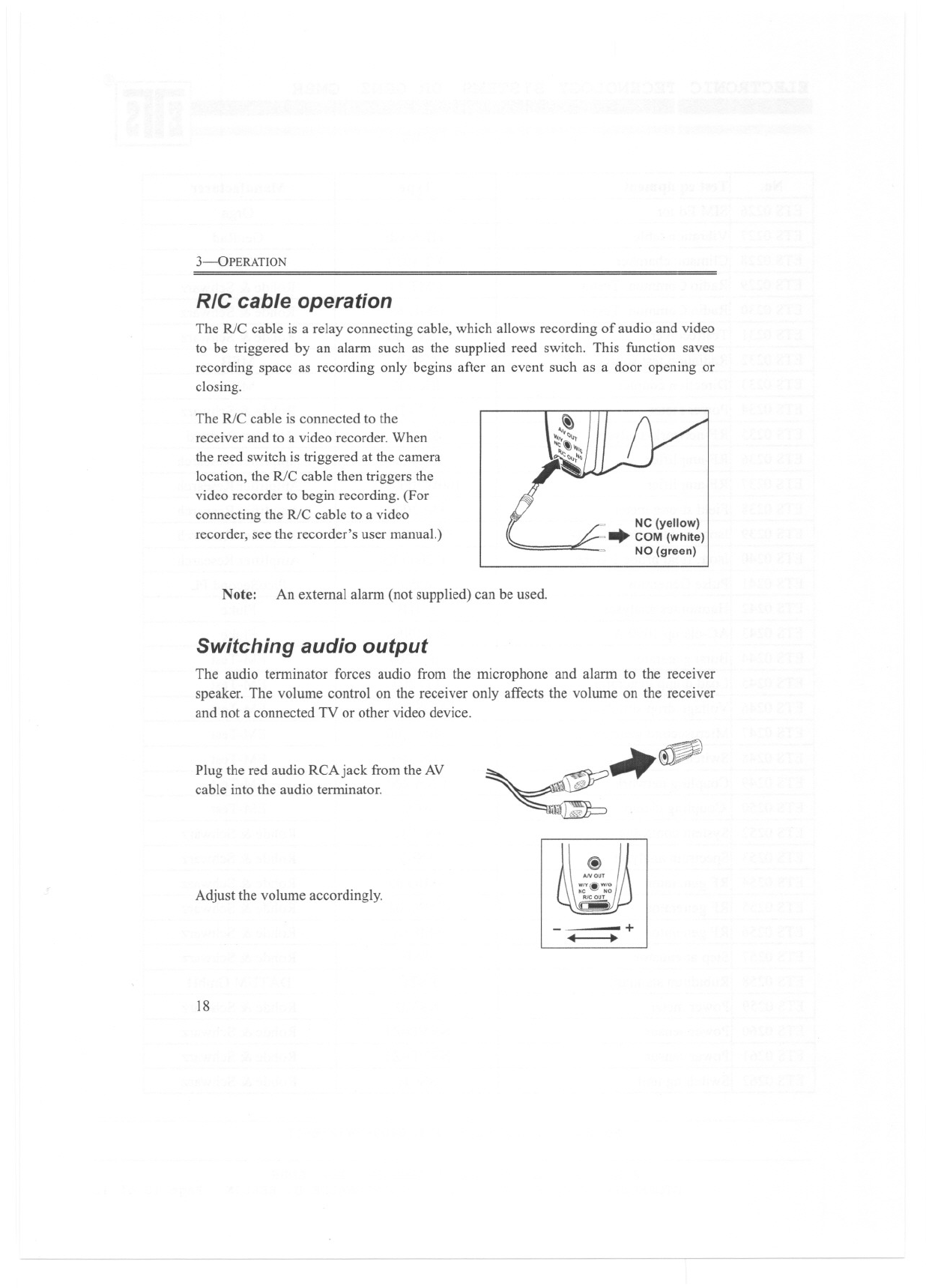
The R/C cable is connected to the
receiver and to a video recorder. When
the reed switch is triggered at the camera
location, the R/C cable then triggers the
video recorder to begin recording. (For
connecting the R/C cable to a video
recorder, see the recorder's user manual.)
Note: An external alann (not supplied) can be used.
Switching audio output
The audio tenninator forces audio from the microphone and alann to the receiver
speaker. The volume control on the receiver only affects the volume on the receiver
and not a connected TV or other video device.
Plug the red audio RCAjack from the AV
cable into the audio tenninator.
Adjust the volume accordingly.
18
~ ~
@
+
4 .
Appendix
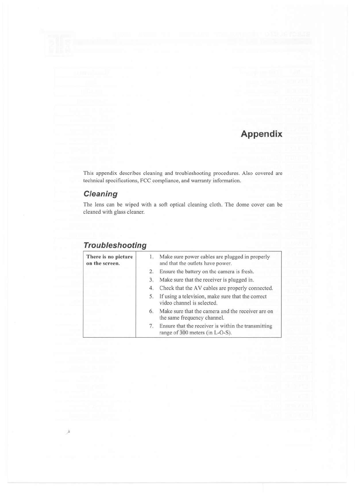
This appendix describes cleaning and troubleshooting procedures. Also covered are
technical specifications, FCC compliance, and warranty information.
Cleaning
The lens can be wiped with a soft optical cleaning cloth. The dome cover can be
cleaned with glass cleaner.
Troubleshooting
There is no picture
on the screen. 1. Make sure power cables are plugged in properly
and that the outlets have power.
Ensure the battery on the camera is fresh.
Make sure that the receiver is plugged in.
Check that the AV cables are properly connected.
Ifusing a television, make sure that the correct
video channel is selected.
Make sure that the camera and the receiver are on
the same frequency channel.
Ensure that the receiver is within the transmitting
range of300 meters (in L-O-S).
2.
3.
4.
5.
6.
7.
;.
ApPENDIX
20
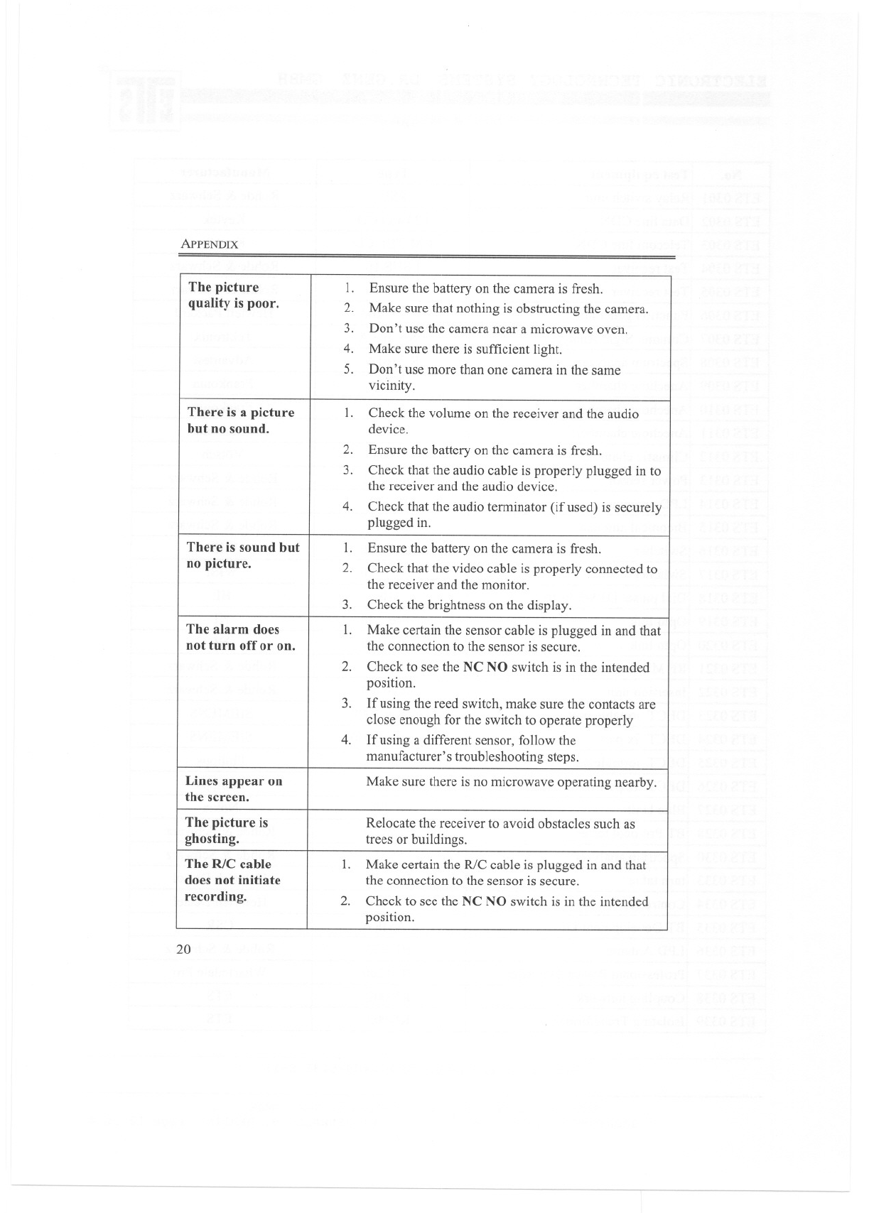
The picture 1. Ensure the battery on the camera is fresh.
quality is poor. 2. Make sure that nothing is obstructing the camera.
3. Don't use the camera near a microwave oven.
4. Make sure there is sufficient light.
5. Don't use more than one camera in the same
vicinity.
There is a picture 1. Check the volume on the receiver and the audio
but no sound. device.
2. Ensure the battery on the camera is fresh.
3. Check that the audio cable is properly plugged in to
the receiver and the audio device.
4. Check that the audio terminator (ifused) is securely
plugged in.
There is sound but 1. Ensure the battery on the camera is fresh.
no picture. 2. Check that the video cable is properly connected to
the receiver and the monitor.
3. Check the brightness on the display.
The alarm does 1. Make certain the sensor cable is plugged in and that
not turn off or on. the connection to the sensor is secure.
2. Check to see the NC NO switch is in the intended
position.
3. lfusing the reed switch, make sure the contacts are
close enough for the switch to operate properly
4. lfusing a different sensor, follow the
manufacturer's troubleshooting steps.
Lines appear on Make sure there is no microwave operating nearby.
the screen.
The picture is Relocate the receiver to avoid obstacles such as
ghosting. trees or buildings.
The RfC cable 1. Make certain the R/C cable is plugged in and that
does not initiate the connection to the sensor is secure.
recording. 2. Check to see the NC NO switch is in the intended
position.
TECHNICAL SPECIFICATIONS
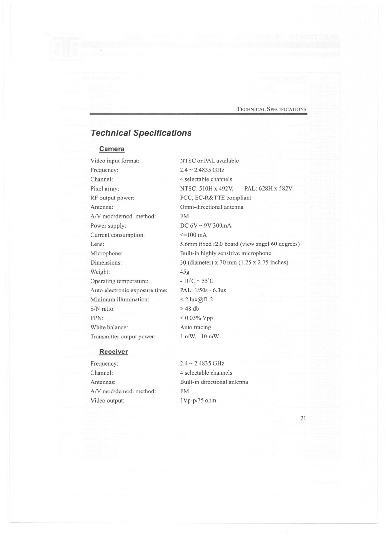
Technical Specifications
Camera
Video input fonnat:
Frequency:
Channel:
Pixel array:
RF output power:
Antenna:
AN mod/demod. method:
Power supply:
Current consumption:
Lens:
Microphone:
Dimensions:
Weight:
Operating temperature:
Auto electronic exposure time:
Minimum illumination:
SIN ratio:
FPN:
White balance:
Transmitter output power:
Receiver
Frequency:
Channel:
Antennas:
AN mod/demod. method:
Video output:
NTSC or PALavailable
2.4 -2.4835 GHz
4 selectable channels
NTSC: 51OH x 492V, PAL: 628H x 582V
FCC, EC-R&TTE compliant
Ornni-directional antenna
FM
DC 6V -9V 300mA
<=100 mA
5.6mm fixed f2.0 board (view angel 60 degrees)
Built-in highly sensitive microphone
30 (diameter) x 70 mm (1.25 x 2.75 inches)
45g
- 10'C - 55'C
PAL: 1/50s - 6.3us
< 2 lux@f1.2
> 48 db
< 0.03% Vpp
Auto tracing
1mW, 10mW
2.4 - 2.4835 GHz
4 selectable channels
Built-in directional antenna
FM
1Vp-p/75 ohm
21
ApPENDIX
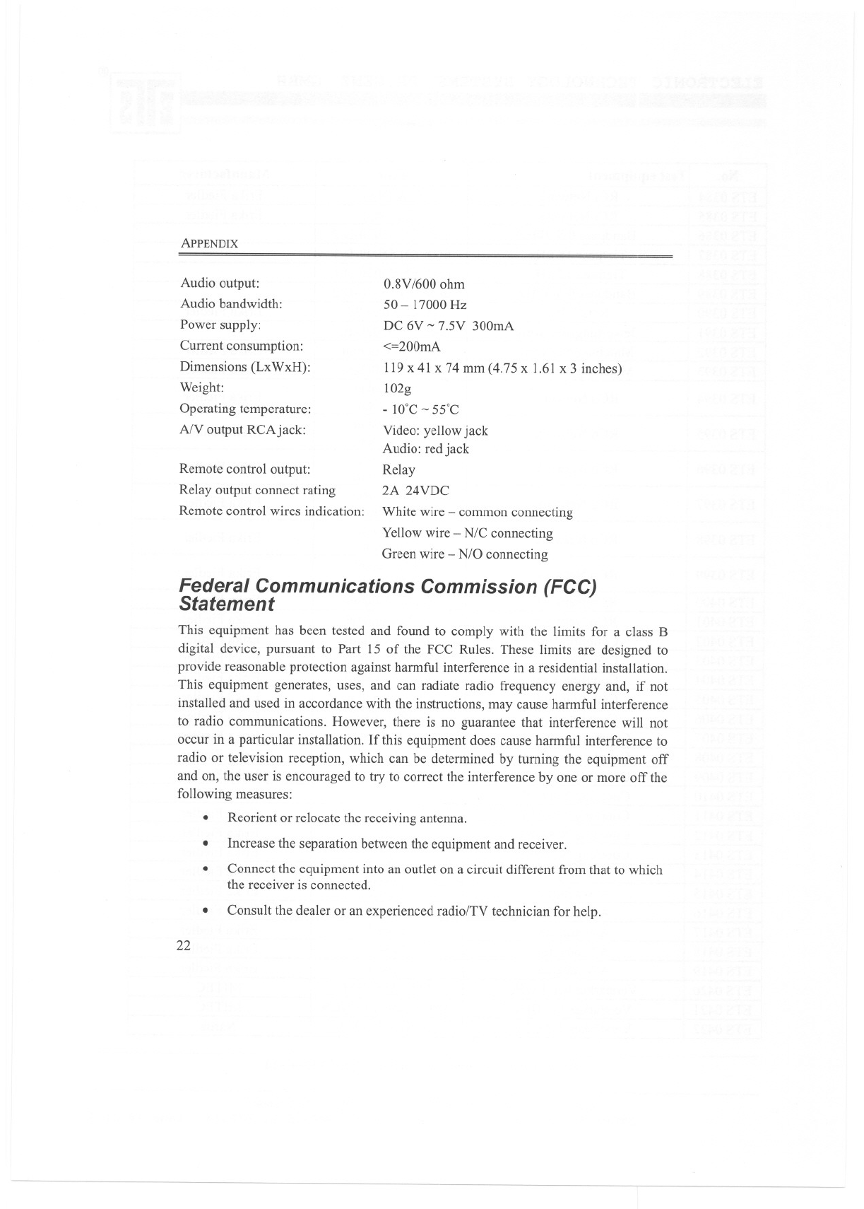
Audio output:
Audio bandwidth:
Power supply:
Current consumption:
Dimensions (LxWxH):
Weight:
Operating temperature:
AlV output RCAjack:
0.8V /600 ohm
50 - 17000 Hz
DC 6V ~7.5V 300mA
<=200mA
119 x 41 x 74 mm (4.75 x 1.61 x 3 inches)
102g
- 10'C ~ 55'C
Video: yellow jack
Audio: red jack
Relay
2A 24VDC
Remote control output:
Relay output connect rating
Remote control wires indication: White wire -common connecting
Yellow wire - N/C connecting
Green wire -N/O connecting
Federal Communications Commission (FCC)
Statement
This equipment has been tested and found to comply with the limits for a class B
digital device, pursuant to Part 15 of the FCC Rules. These limits are designed to
provide reasonable protection against harmful interference in a residential installation.
This equipment generates, uses, and can radiate radio frequency energy and, if not
installed and used in accordance with the instructions, may cause harmful interference
to radio communications. However, there is no guarantee that interference will not
occur in a particular installation. If this equipment does cause harmful interference to
radio or television reception, which can be determined by turning the equipment off
and on, the user is encouraged to try to correct the interference by one or more off the
following measures:
.Reorient or relocate the receiving antenna.
.Increase the separation between the equipment and receiver.
Connect the equipment into an outlet on a circuit different from that to which
the receiver is connected.
.
.Consult the dealer or an experienced radio/TV technician for help.
22
WARRANTY
Unauthorized changes or modifications of this device could void the user's
authority to operate the equipment.
Operation is subject to the following two conditions:
(l) This device may not cause harmful interference.
.
(2) This device must accept any interference received, including interference that may
cause undesired operation.
Warranty
The warrant is for one year from the date of purchase. Please retain the sales receipt as
proof of purchase. During the one-year warranty period, the product is eligible for
replacement in case of defects in material and workmanship. In such cases, the
defective unit will be repaired or replaced by the manufacturer or an authorized
distributor. However, this warranty does not cover damages caused by improper use or
from unauthorized modifications by third parties. In addition, this warranty does not
cover expendable materials and defects, which constitute as normal wear and tear.
23