Actwell Technology ACT-205TX Wireless Control Security/Alarm A/V Transmitter User Manual
Actwell Technology Inc. Wireless Control Security/Alarm A/V Transmitter Users Manual
Users Manual
\~
...\>.
Fe CEO681<D\
....
Edition
First edition, September 2004
Copyright information
This publication, including all photographs, illustrations and software, is
protected under international copyright laws, with all rights reserved. Neither this
manual, nor any of the material contained herein, may be reproduced without
written consent of the author. ,
',\
".'. . @ September, 2004
.~
~,
Trademarks
All product names used in this manual are the properties of their respective
owners and are acknowledged.
'-4"-
'.
FROM: ACTWELLTECHNOLOGYINC. FAR NO. : 008862 22787363 SEP.22200409:28AMP. 3
Safety and battery use
.Read and follow any warnings ill tbjs manual.
.Re.ad the regulatory compliance notice on page lIS.
.When not in use,remove any batteriegand store them in a cool dryplace.
.Do not me the camerain temperatUresbelow-10 or exceeding55 degrees
Celsius
.Don't dispose mused batteri8S with household waste. Return the batteries to
your dealer or to a special disposal service.
Any servicing must only be done by qualified personnel.
.
.Do not set up or use the receiver or camera in a wet or damp enviromnent
Save these instructions for future reference.
.
About this manual
This manual is designed to assist users with setting up and operating #ACT-205.
Information in this document has been carefully checked for accuracy; however,
no guarantee is given as to the correctness of the contmts. Thr: infO1'JMtion
contained in dUs document is subject to change without notice.
ii
FROM : ACTWELLTECHNOLOGYINC. FAX NO. 00886222787363 SEP.22 200409:28AMP. 4
Tableof contents
I-GETIING ST.AR't'ED 1
CHECKING'J11EPACKINGLIST 1
.l.DENTlFY1NG PART'S """"'" """"""" , ..." 2
,., ,.--.
Transmitter , ).
Receiver. m """"" m :J
2-sETI1N G UP... .4-
PRE-SETUPTESTING......................................................................................................
MAKn-iGCONNECTIONS """ :s
Receiver $etup " ..: 5
Transmitter setup E,.
3--0 PERAnON' ..._0"_"'_"'"- ?
0PERA11NG:RESTRICTIONS """" " 7
MATc:H1NGCHANNELS ...".. .." ""'" B
STANDARD/'J..WAYs-oN OPERA11oN"""""""""""" ,.. 'i
REEDswrrCH OPER.A:rIoN q
Rcf!!dswitch instal/anon : q
Set (0 NO (Nonnal Open) 'I
SeIIO NC (NQ17IJalClosed) ,q
WCCABLE OPERATION ;D
SwrrCHJNGAUDfOOUTPur """"' " IC
APPENDIX "Ii
CI..EA:NJNG """"""""""'" .......
TR.OUBLESHOOTIN'G "
TE~CAL _SPECIFICATIONS J~
.Transminer , H
Receiver """"""""" '... 14-
FEDERAL COMMUNICATIONSCOMMISSION(FCC) STATEMENT 14
WARRANTY m ,>
iii
FROM: ACTWELLTECHNOLOGYINC. FARNO. : 00886 2 22787363 SEP.22 200409:28AMP. 5
i-Getting started
" ....
Congra1ulationson your purchase of the remotesIstIMr'. Use this ~ld'#.IJI to monitor
locations wire1essly,as a stand-alone solution or integrated into an existing alann
~~m. .
Checking the packing list
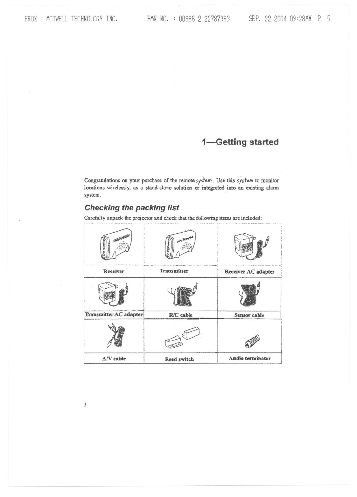
Carefully unpack the projectot" and check that the following items are included:
:~
~:.""""""""""',"""""""""""""""'"
~.~, .....
14P "'.
~{I
TraDBmitterAC adapter RlC cable SeDS~ cable
')I ~e? ~
AIV cable 'Reed switch Audio unDiDator
FROM: ACTWELLTECHNOLOGYINC. FARNO. : 00886 2 22787363 SEP.22 200409:29AMP. 6
IDENTIFYINGPARTS
-
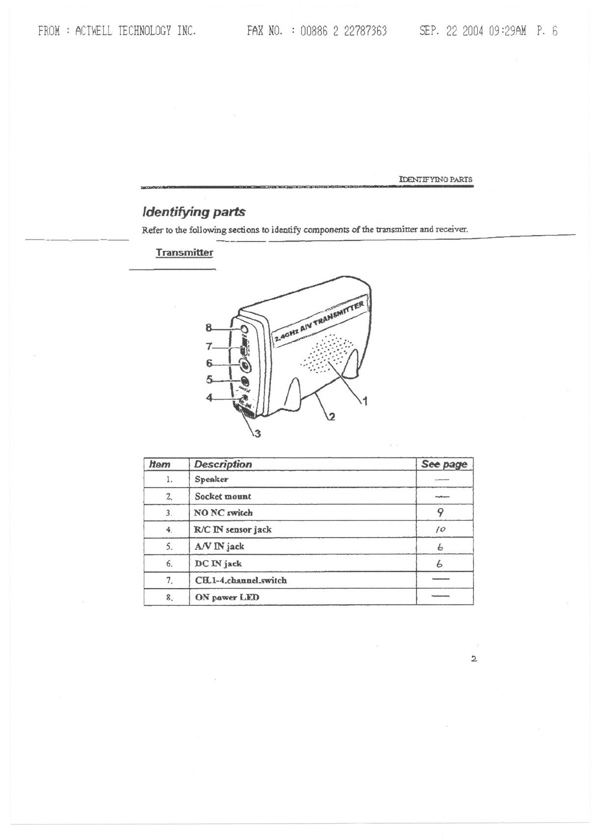
Identifying parts
Refer to the following sections to identify components of the transmitter and receiver.
-' '-
Transmitter
2.
Item De$cn"ption S page
1. Speaker -
2. Socket mount -
3. NO NC 5:wiccla 9
4- RIC IN sensor jack 10
5. A/V IN jack h
6. DC IN jack b
7. CH.1-4.channel.mtch -
8. ON power LED -
FROM: Acn~LL TECHNOLOGYINC. FARNO. : 00886 2 22787363 SEP.22 200409:29AMP. 7
I-G£T11NG STARrED
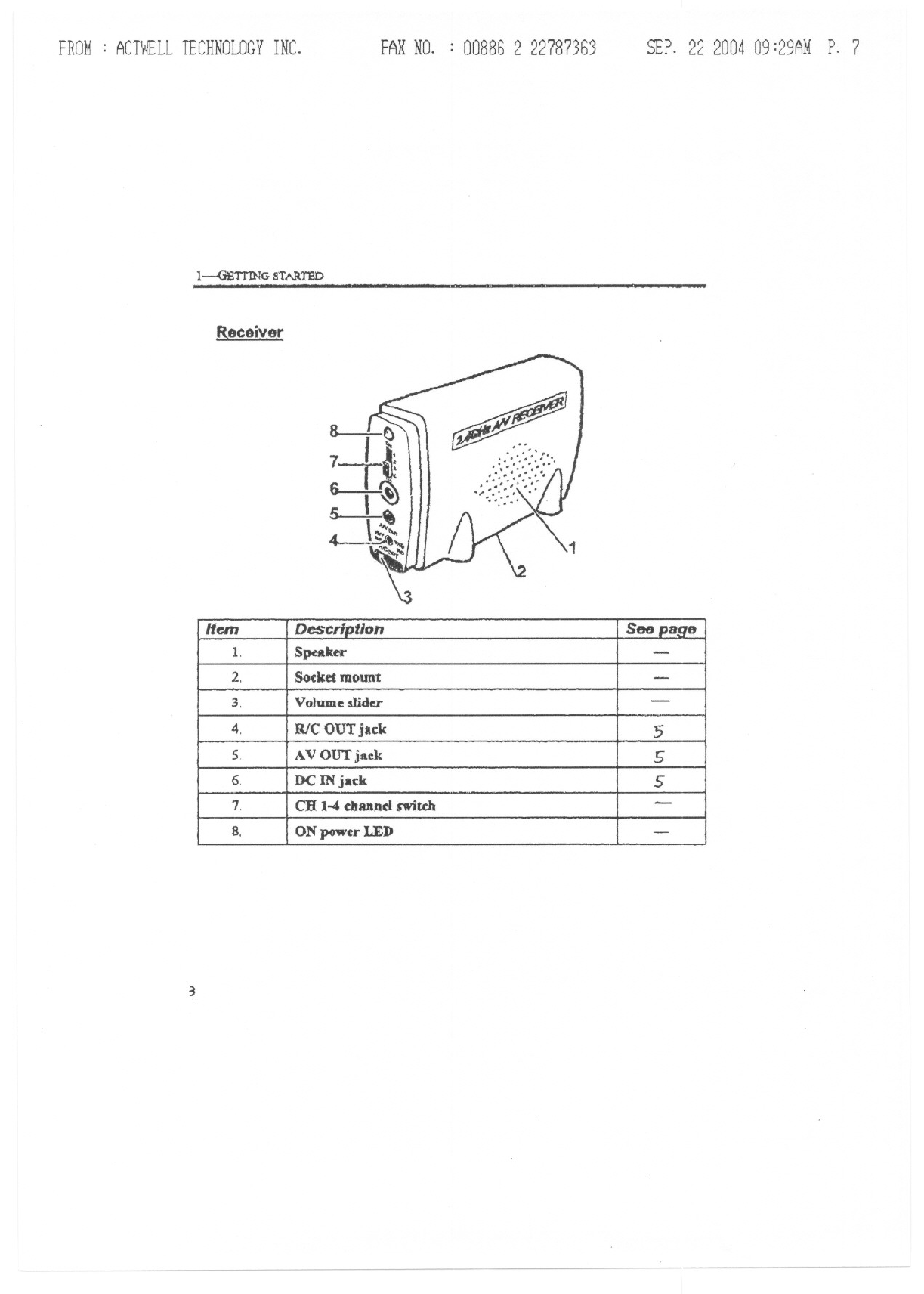
Receiver
~
'~~:/'
~
+:::u
'}"
..::., .
/'
1
3
Hem Description See page
1. Speaker -
2. Socket mount -
3. Volume slider -
4. WC OUTjack 5
5. AV OUTjaa 5
6. DC INjack 5
7. CHI-4 channelswildt -
8. ON power LED -
FROM: ACTWELLTECHNOLOGYINC. FAXNO. : 00886 2 22787363 SEP.22 200409:29AMP. 8
2-5etting up
This section explains the mounting options and setup of the remote camera. However.
before installing the camera check that all the parts are wolking as described below.
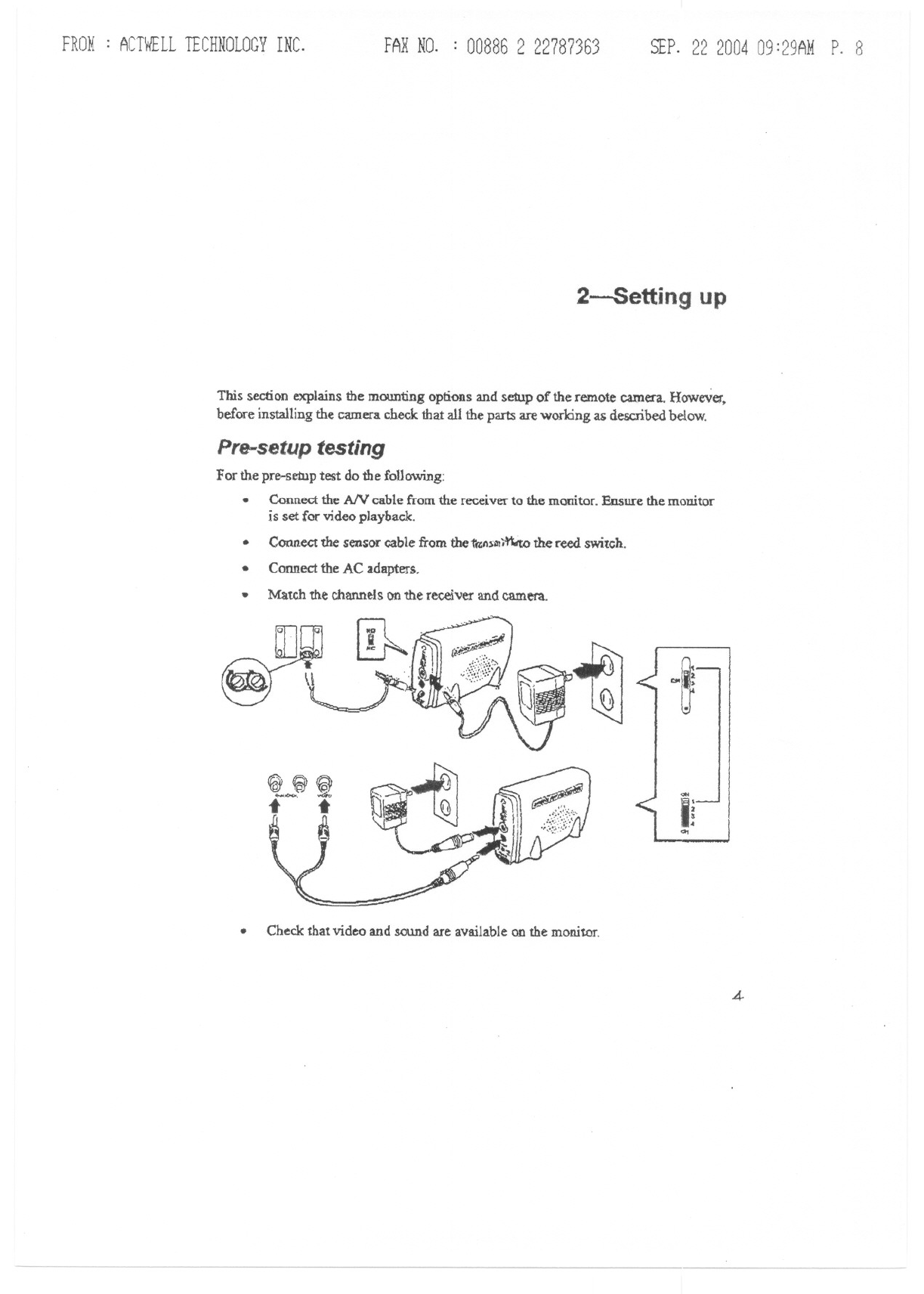
Pre-setup testing
For the pre-setup test do the following:
.Connect the AN cable from the receiver to the monitor. Ensure the monitor
is set for video playback.
.Connect the sensor cable from the 'ta:n~1!1j~ the reed switch.
.Connect the AC adapters.
Match the channels on the receiver and camera.
.
~bl»J
~t
~~@
,.<i.
t t
~
,p
Q~~
<>It
Ii
Q1
.Check that video and sound are available on the monitor.
4
FROM: ACTWELLTECHNOLOGYINC. FAXNO. : 00886 2 22787363 SEP.22 200409:30AMP. 9
2-SBTIING UP
-~ - ~~~~
.Test the sensor operationby moving the reed switch apart and changingthe
NO NC setting on the transmitter.
If some function$ do not work, check the corresponding section in this
manual before installing the system.
.
Makingconnections
The receiver is designed to connect to different devices such as a Tv, VCR, or digital
videa reoorder (DVR).
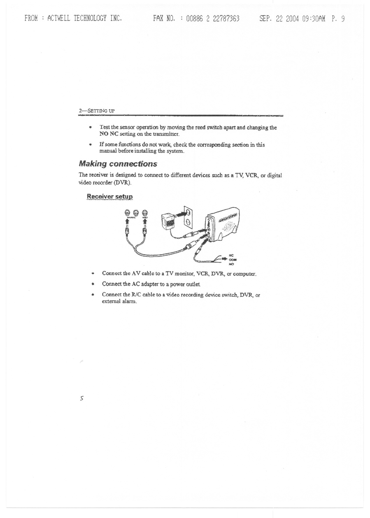
Receiver setul!
.Connect the AV cable to a TV monitor, VCR, DVR, or computer.
Connect the AC adapter to a power outlet.
Connect the RIC cable to a video recording device switch, DVR, or
external alarm.
.
.
5
FROM: ACTWELLTECHNOLOGYINC.
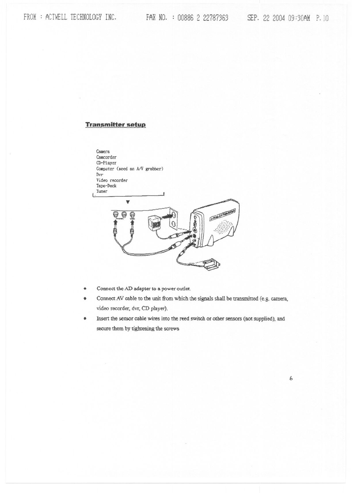
"[ran_amlttersetup
FARNO. : 00886 2 22787363 SEP.22 200409:30AMP.lO
CalDera
Call1corder
CD-Player
~ter (need an AlV grabber)
Dvr
Video recorder
Tape-Deck
Tuner
(.
Connect the AD adapter to a power outlet.
Connect AV cable to the unit from which the signals shall be transmitted (e.g. camera,
video recorder. dvr, CD player).
Insert the sensor cable wires into the retd switch or other sensors (not supplied), and
secure them by tightening the screW'S
...
e~~
-- i
.
.
.
b
FROM: ACTWELLTECHNOLOGYINC. FARNO. : 00886 2 22787363 SEP.22 200409:30AMP.II
3-0peration
The cbaptc::rdescribes the operation of the system.
Operating restrictions
.Avoid using the camera in humid locations. If condensation occurs, allow the
camera to dry before operating,
.Do not u~ in temperatures bclow -10 degrees Celsius or above 55 degrees
Celsius.
.PrIDdmity to microwave ovens can cause interference and reduce the quality
of the audio and video signals.
.Using two camerasin the same vicinitymay result in sound and picture
interference.
7.
FROM: ACTWELLTECHNOLOGYINC. FARNO. : 00886 2 22787363 SEP.22 200409:30AMP.12
3-QPERATION -. ~.
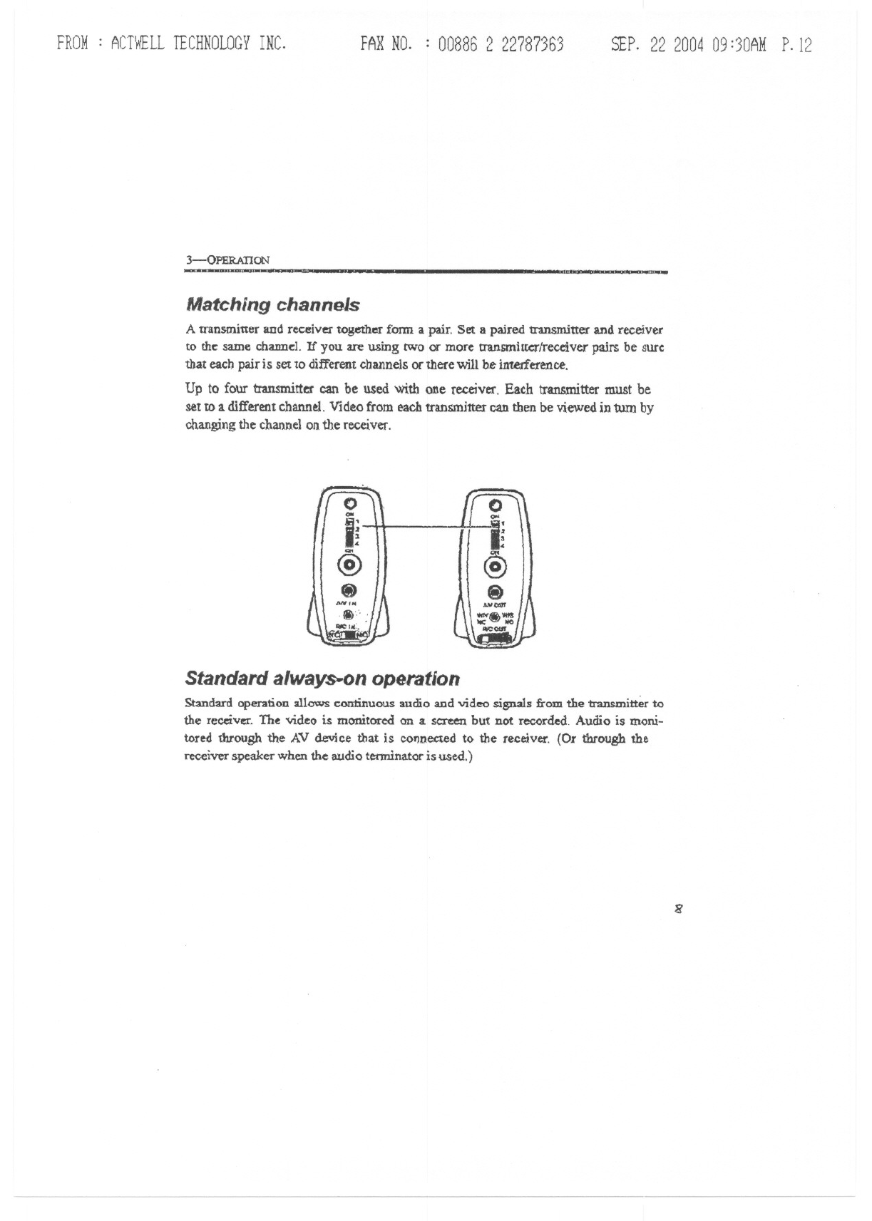
Matching channels
Atran~mitter and receiver together fonn a pair. Set a paired transmitter and receiver
to the: same chamJe:l. If you are using two or more transmittcrlreceiver pairs be sure
that eacb pair is set to different channels or there will be interference.
Up to four transmitter can be used with one receiver. Each transmitter must be
set to a different channel. Video from each transmitter can then be viewed in turn by
changing the channel on the receiver.
0
QII
i~
@
.
-'N
Standard always.on operation
Stmdard Qpe.ranoDallows continuous audio aDdvideo signals from the transmitter to
the receiver. The video is monitored on a.screen but not recorded Audio is moni-
tored through the AV device that is cofmec:tedto the receiver. (Or through the
receiverspeakerwhen the audioterminatoris used.)
8
FROM: ACTWELLTECHNOLOGYINC. FAXNO. : 00886 2 22787363 SfP. 22 200409:31AMP.1)
REED SWITCH OPERATION
--
Reed switch operation
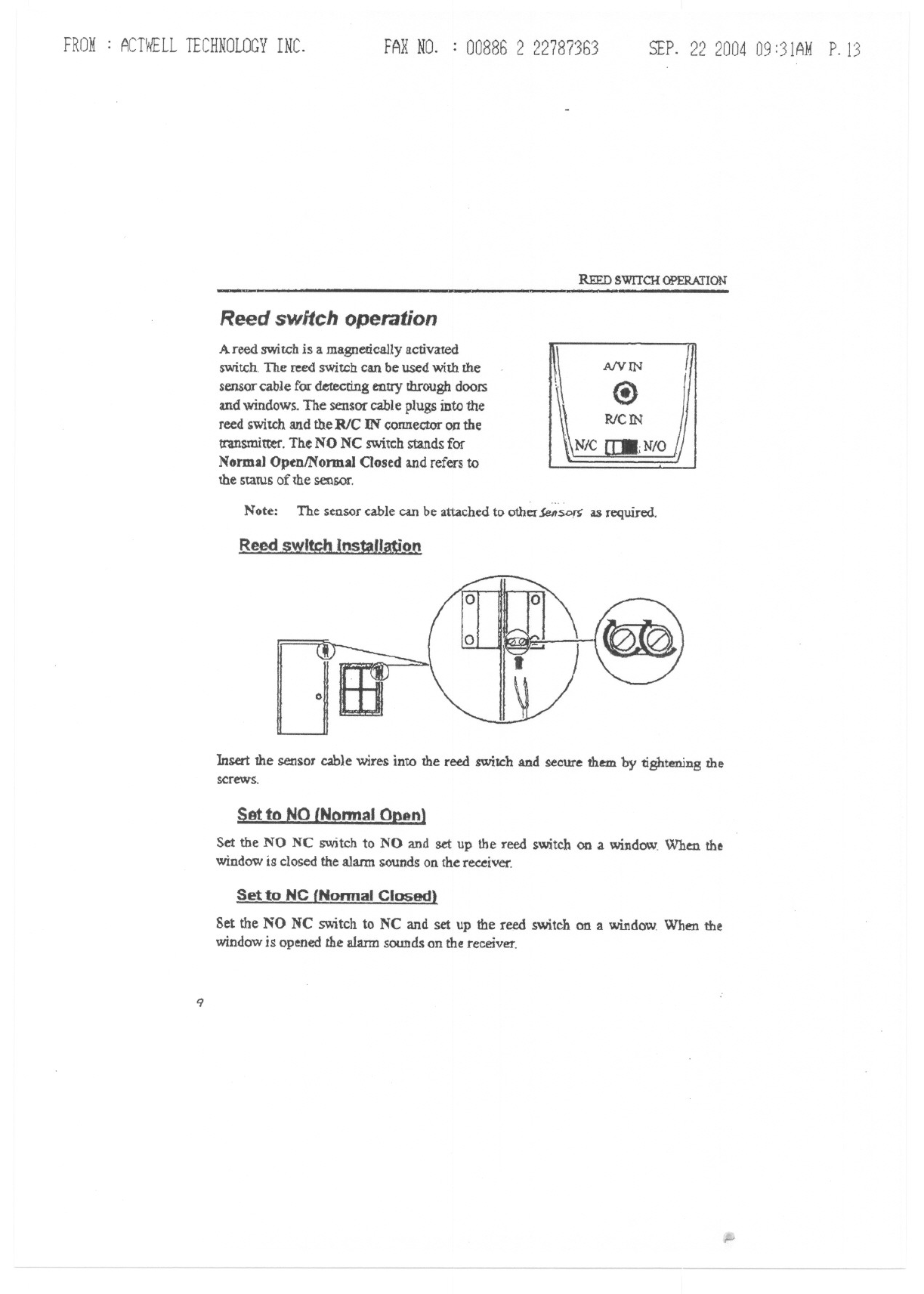
A reed switG'his a magnetically activated
switch- The reed switch can be used with the
sensor cable for detecting entry through doors
and windows. The sensor cable plugs into the
reed switch and the RlC IN connector OJ!the
transmitter. The NO NC switch stands for
Normal OpenlNormal Closed and refers to
the statUs of the sensor.
AIVIN
Note: The sensor cable can be attached to other $enSD~ as required.
Reed swl~h (nstaJl~O{1
0
Insert the sensor cable wires intO the reed switch and secure them. by tightening the
screws.
Set the NO NC switch to NO and set up the reed switch on .a window. When the
window is closed the alarm sounds on the receiver.
Set to NC {Nannal Closed)
Set the NO NC switch to NC and set up the reed switch on a window When the
windowis openedthe alarmsounds on the receiver.
9
,.,
FROM: ACTWELLTECHNOLOGYINC. FAX NO. : 008862 22787363 SEP. 22 200409:31AMP.14
3-0PERATION -
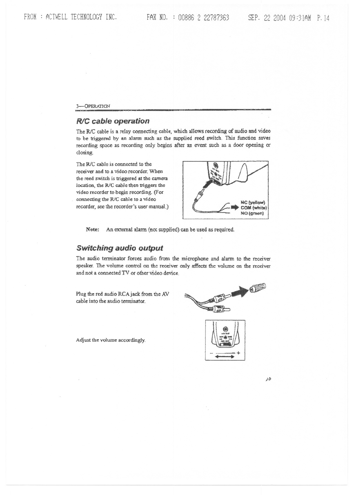
R/C cable operation
TheRICcableis 3.relay connectingcable, which allows recording of audio and video
to be triggered by an alarm such as the supplied reed switch This function saves
recording space as recording only begins after an event such as a door opening or
closing.
The RlC cable is connected to the
receiver and to a video recorder. When
the reed switch is triggered at the camera
location, ~ R/C cable then trigeer'S the
video recorder to begin re<:ording. (For
connecting the RJC cable to a video
recorder, see the recorder's user manual,)
Note: An external alarm (not supplied) can be used as required.
Switching audio output
The audio terminator forces audio fretn the microphone and alarm to the receiver
speaker. The volume control on the tecdver only affects the volume on the receiver
and not a.connected TV or other video device.
Plug the red audio RCAjaclc from the AV
cable into the audio terminator.
A~u~thev~umea"ocdin~y
~~
)f>
<i
IoN"'"
..."'.- J
.,,;::./
-+
..,
FROM: ACTWELLTECHNOLOGYINC. FAXNO. : 008862 22787363 SEP.22200409:31AMP.15
Appendix
This appendix describes cleaning and troubleshooting procedures. Also covered are
technical specifications, FCC compliance, and warranty information.
."'"
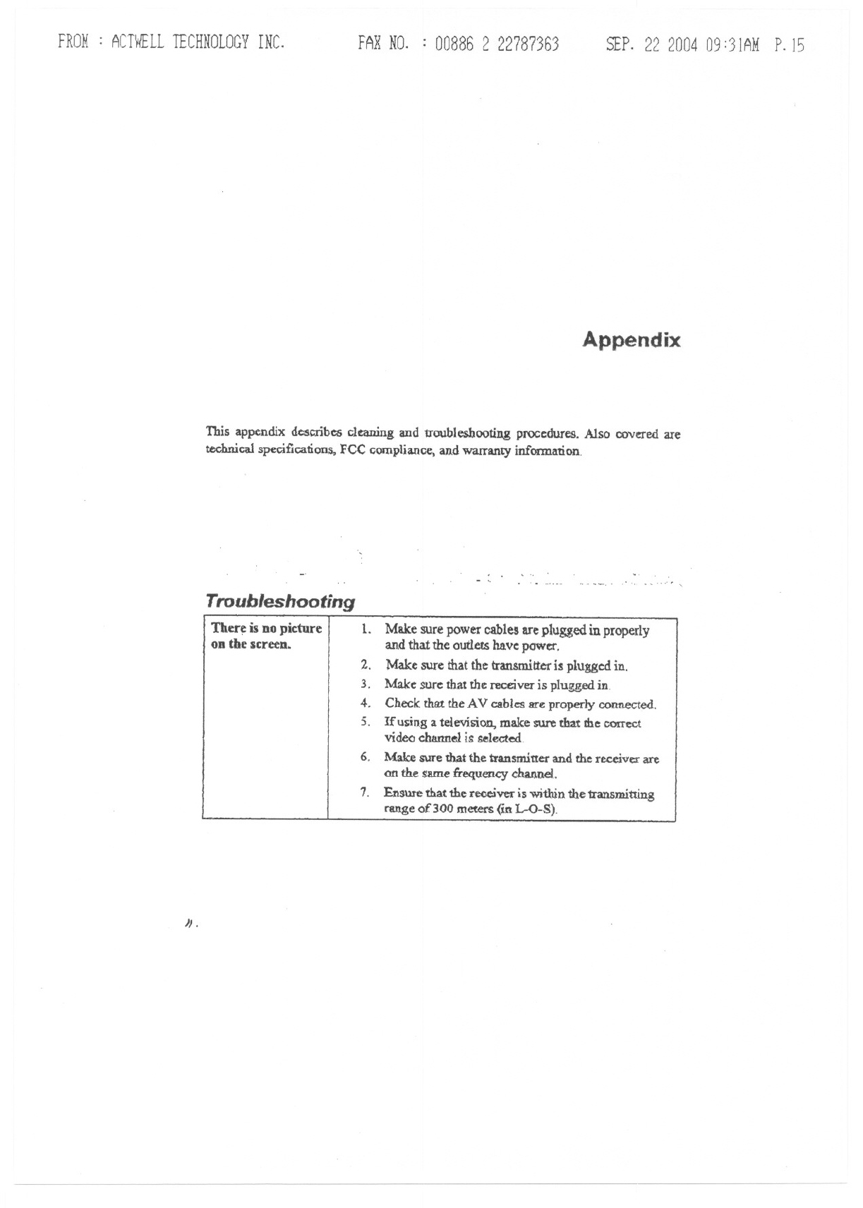
Troubleshooting
Ther~ is DOpicture II.
on the screeD. Make sure power cables are plugged in properly
and that the outleu have:power.
2. Make sure that the transmitter is plugge:d in.
3. Make: sure:that the receiver is plugged in.
4. Check that the AV cables are properly connected.
5. Ifusing a television, make sure that me conect
video channel is selected
6. Make sure that the transmitter and the receiver are
on tb.e same :frequency channel..
1. Ensure that 1he receiver is witbin the transmitting
range of 300 meters (in 1.-0-8).
".
FROM: ACTWELLTECHNOLOGYINC. FAXNO. : 00886 2 22787363 SEP.22200409 :32AMP.16
APPENDIX
12
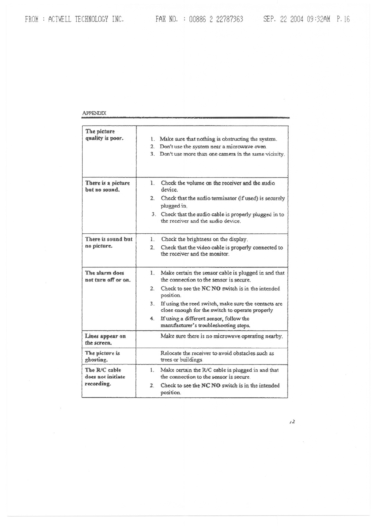
The picture
quality is poor. 1. Make sure that nothing is obstructing the system.
2. Don't use the system near a microwave oven.
3. Don't use more than one camera in the same viciIrity.
There a picture 1. Check the volwne an the receiver and the audio
but DOsound. device.
2. Check that the audio terminator (ifulled) is securely
plugged in,
3. Check that the audio cable is properly plugged in to
the receiver and the audio device.
There is sound but 1. Check the brightness on the display.
no picture.. 2. Check that the video cable is properly connected to
the receiver and the monitor.
The alarm does 1. Make certain the sensor cable is plugged in and that
not turn off or on. the connection to the sensor is secure.
2, Check to see the NC NO switch is in the intended
position.
3. If using the reed switch, make sure the contacts arc
close enough for the switch to operate properly
4, !fusing a different SeDSOJ,follow the
manufacturer's troubleshooting steps.
Lilies appear on Make sure there is no microwave operating nearby.
the screen.
The p.ct1lre is Relocate the receiver to avoid obstacles such as
ghosting. trees or buildings
The RlC cable 1. Make certain the RJC cable i plugged in and that
does not initiate the connection to the sensor is secure.
recording. 2. Check to see the NC NO switch is in the intended
position.
FROM: ACTWELLTECHNOLOGYINC. FAXNO. : 008862 22787363 SEP. 22200409:32AMP.17
TEcHNICAL SI>ECJFICAlIONS
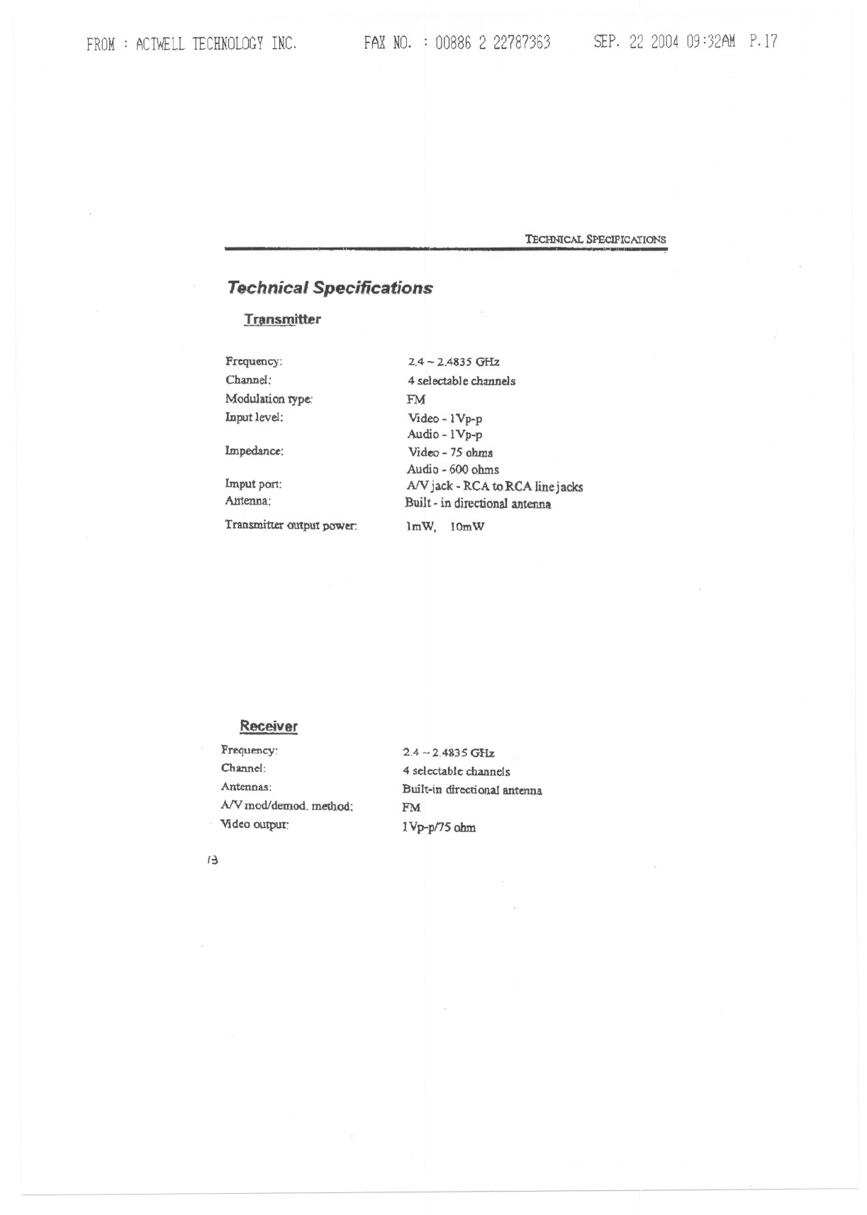
T!l!m!mitter
TechnicalSpecifications
Frequency:
Channel:
Modulation type:
Input level:
1mpedance:
Imput port:
Antenna:
Transmitter output power:
Receiver
Frequency:
Channel:
Antennas:
AN mod/demod. method:
Video output:
,~
2.4 - 2.4835 GHz
4 selectable channels
FM
VIdeo - lYp-p
Audio -lVp-p
Video - 7S ohms
Audio - 600 ohms
AN jack. RCA toRCA linej acks
Built -in directionalantenna
ImW, lOmW
2.4 -2.4835 GHz
4 sele.ctabkchannels
Built-in directional antenna
PM
1Vp-p/15 ohm
FROM: ACTWELLTECHNOLOGYINC.
APPENDIX
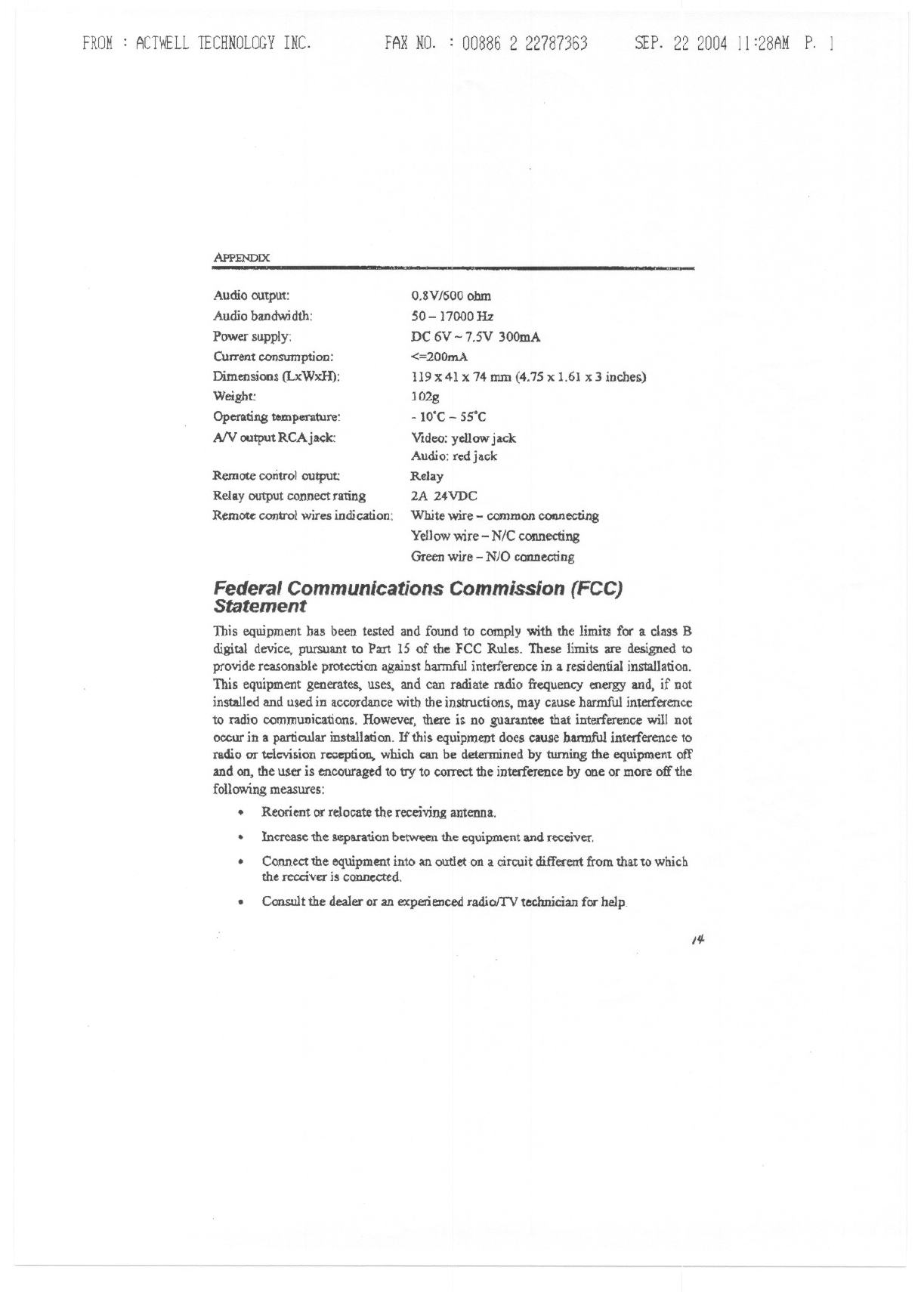
Audio outpUt:
Audio bandwidth:
Power supply:
Current ronsumption:
Dimensions (LxWxH):
Weight:
Operating temperature:
AN outputRCAj~k:
Remote control output:
Relay output connect raung
Remote conirol wires indication:
FAXNO. : 008862 22787363 SEP.22 2004 11 :28AM P. 1
-
O.8VJ600ohm
50-1 7000Hz
DC 6V - 7.5V 300mA
<=200mA
119 X41 X74 mm (4.75 x 1.61 x 3 inches)
JO2g
- WC - 55'C
Video: yellow jack
Audio: red jack
Relay
2A 24VDC
White wire -common COI'1I1ecUng
Yellow wire -N/C connecting
Green wire -NJO connecting
Federal Communications Commission (FCC)
Statement
Tbis equipment bas been tested and found to comply with the limiu for a class B
digital device, pursuant to Part 15 of the FCC Rules. These limits are designed to
provide reasonable protection against harmful interference in a residential installation.
This equipment generates. uses, and can radiate radio frequency energy and, if not
installed and used in accordance with the instructions, may cause harmful interference
to radio communications. However, there is no guarantee that interference will not
occur in a particular installation. If this equipment does cause bannful interference to
radio or television reception,. wbich C8I1be determined by turning the equipnl.ent off
and on, the user is encouraged to try'to correct the interference by one or more off the
following measures:
.Reorient or relocate the receiving antenna.
.Increase the separation betWeenthe equipment and receiver.
Co.nnectthe equipment into an ou:tIeton a circuit different from that to which
the rccciV£Iis connccred.
.
.Consult the dealer or an experienced radiolTV technician for help
I#-
-.
.... w~
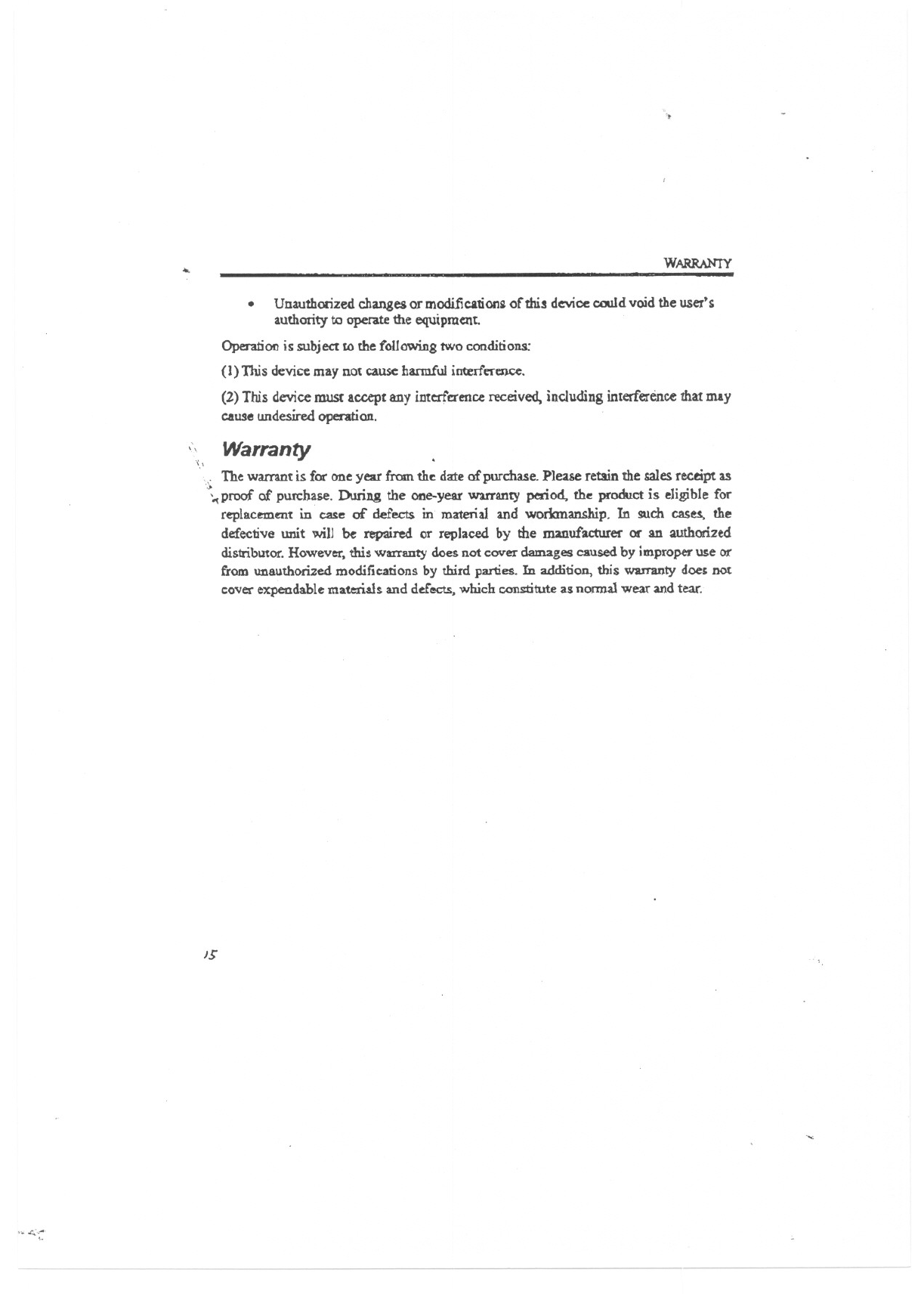
.Unauthorized changes or modification~ of this device oould void the user's
authority to operue the equipment.
Operation is subject to the following tWo conditions:
(1) This device may not cause hannful interference.
(2) This device must accept any interference received, including interference that may
caust! undesired oper-ation.
",I Warranty
"
\. The warrant is for one year fromthe da:teof purchase.Please retain the salesreceipt as
\proof of purchase. During the one-year warranty period, the product is eligible for
replacf:II1altin case of defect$ in material and workmanship. In such cases, the
defective unit will be repaired Of replaced by the manufacturer or an authorized
distributor.However,this warranty does not cover damages causedby improperuse or
from unauthorized modifications by third parties. In addition. this warnmty docs not
coverexpendablemateria.lsand de.f'ects,which c.orn:tituteas nonna}wear andtear.
15
., <::