Acuity Lighting FCS7TSN Blue Tooth enabled Light Control User Manual
Acuity Brands Lighting, Inc. Blue Tooth enabled Light Control Users Manual
Users Manual

User Guide
Based of FW 103.18
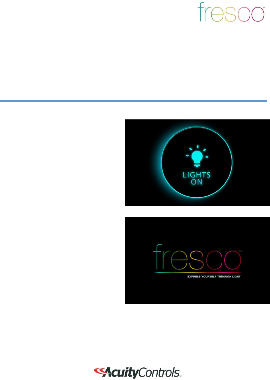
Lights On
2
Overview
“Lights On” is what you will see when the room is off and when pressed will activate the first
lighting scene.
1.
This screen is displayed when the room
lighting is OFF, and the screen IR
proximity sensor has been
activated
2.
If the
LIGHTS ON
screen is not
pressed,
it will dim and then go dark after a
set
period of time. This timeout can
be
adjusted within the
ME
NU
>S
CR
EE
N
setup
3.
The
FRESCO
logo page will
display
when the screen goes into time
out.
4.
The
LIGHTS OUT
and/or the
FRESCO
logo screen settings can be set to
“
not
display” if desired. This change is
made
within the
MENU>SCREEN
setup
3
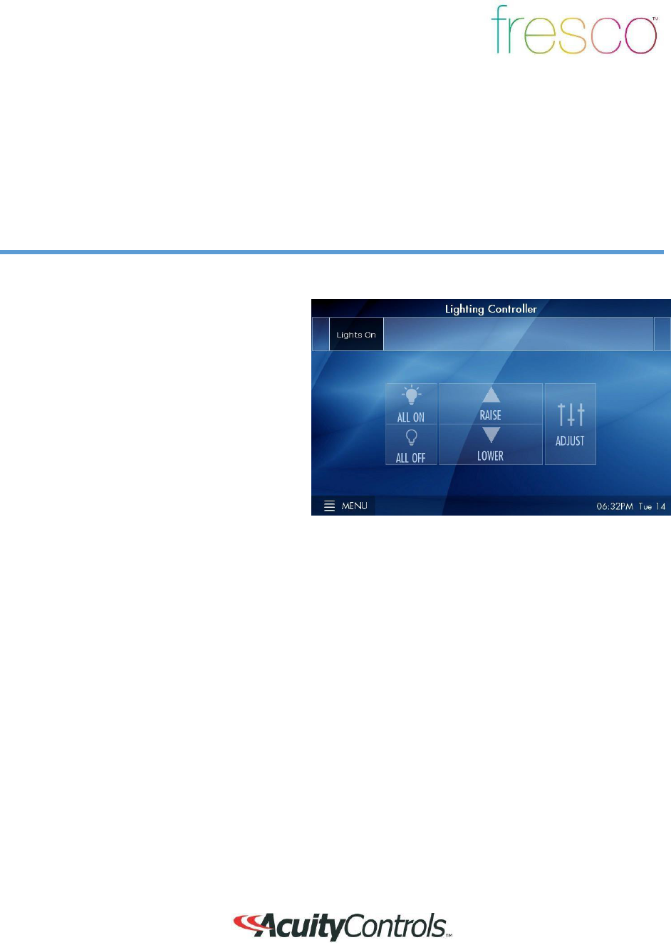
Home Screen
Overview
T
urn
room
l
igh
t
ing
o
n/of
f
,
a
c
t
iv
a
t
e
scenes,
m
a
st
er
ra
ise/
l
o
w
er
l
igh
t
ing
l
ev
e
l
,
access to
l
igh
t
ing
z
o
nes,
menu access
for system
s
et
up,
a
nd
current
d
a
t
e/t
im
e
1.
Controller name is unique and
modified
within
MENU
settings
2. Scrollable scene bar displays up to 6
programmable scenes per page. Up to
36 scenes can be created per fresco
station
3.
Master control room on/off
state,
raise/lower current scene, and
access
additional lighting zones
AD
JUST
4. MENU
accesses system
setup
5. Date/Time displayed and setup wi
thin
MENU
4
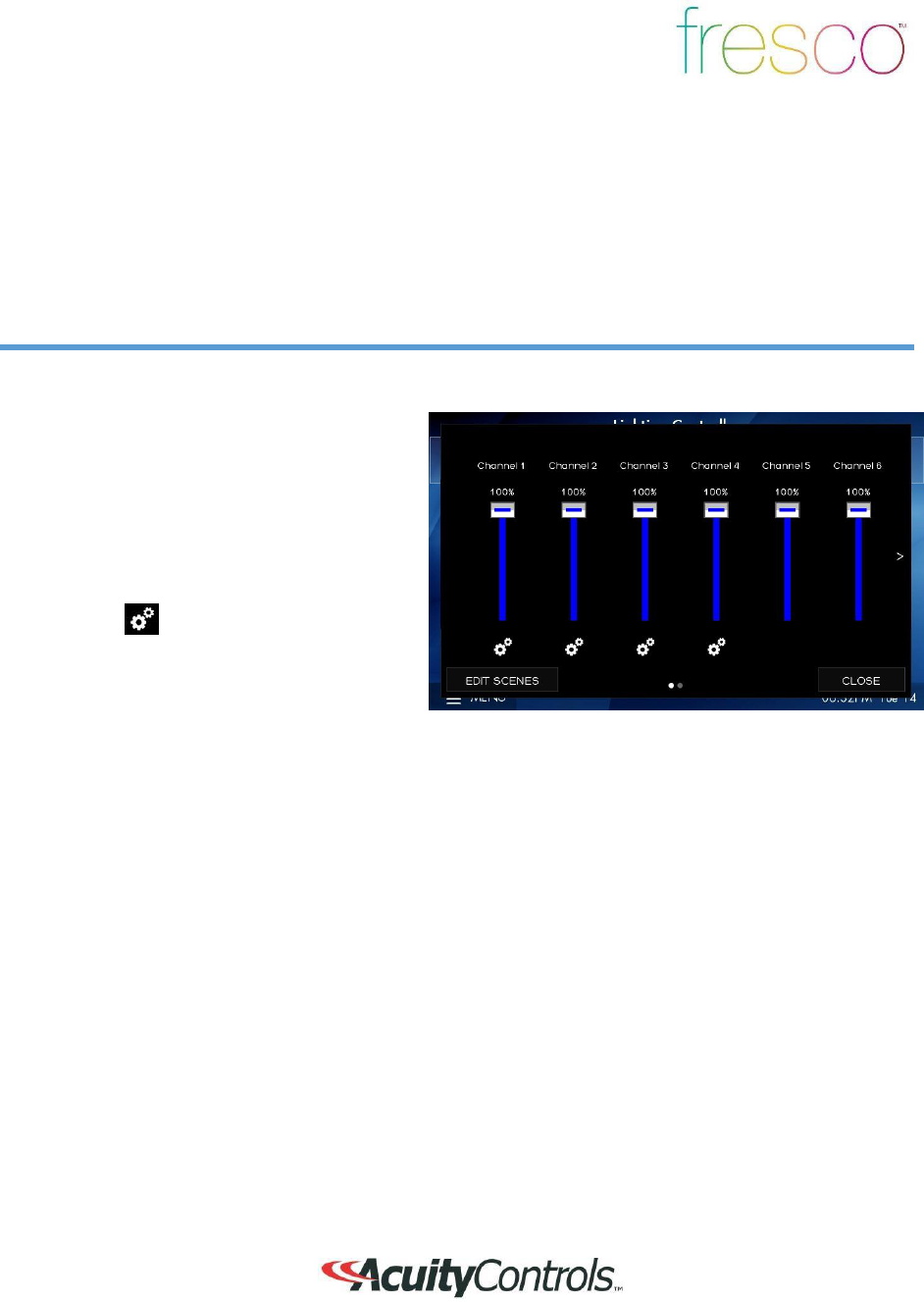
Lighting
Channels
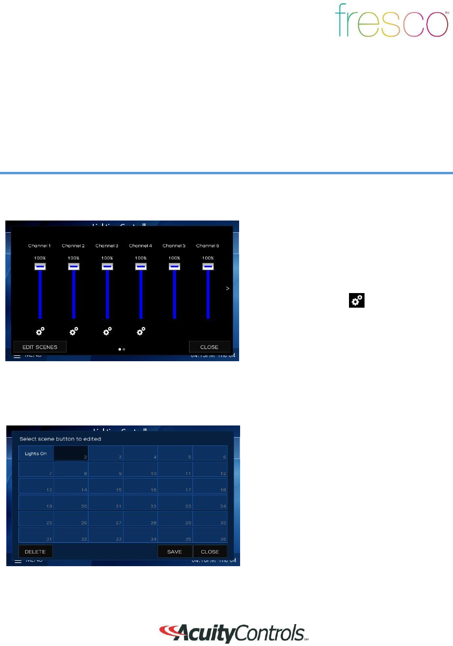
Overview
Control up to 36 individual zones of lighting using the sliders or rocker switch. Adjustments
such
as intensity, color and color temperature are also controllable
here
1.
Channels control individual areas of
lighting. These can control zones o
r
multiple zones (Groups) of lighting.
Groups can be created within the
system
menu setup. The channel names can be
personalized within the system
setup
settings
2.
The icon
(Attribute Control) below
the
channel intensity slider
indicates
additional control of DMX lighting such as
color and color temperature
3.
EDIT SCENES
accesses scene setup
and configuration. Once created scenes
are displayed/accessed from the home
screen
5
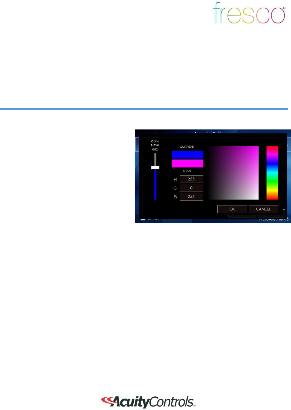
DMX RGB Control
Overview
Control color intensity, hue, and saturation for DMX controlled RGB
fixtures
1.
Raise or lower overall intensity for
the
lighting zone
2.
RGB values are displayed as colors
change. Input specific values be
pressing any of the RGB value fields
3.
Change overall color (hue) by
pressing
anyway in the color field
4.
Change color saturation by touching
anywhere in the large color box
6
DMX Tunable White
Control
Overview
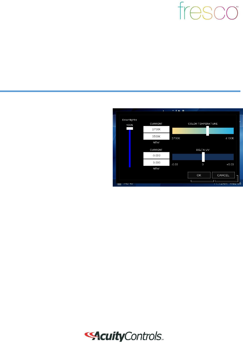
Control intensity, color temperature and hue for DMX controlled tunable white
fixtures
1.
Raise or lower overall intensity for
the
lighting zone
2. Adjust color temperature by sliding
the
handle (range is specific to
fixtu
re)
3.
Adjust hue for added effect
(only
applicable to supported fixtures)
7
Scene
Crea
t
ion
Overview
Each fresco station supports up to 36 lighting scenes. Scenes can made up of multiple lighting
channels,
1. Adjust individual channel intensity levels
2. If available adjust color and/or color
temperature setting using by pressing
the
attribute
icon
3. After making adjustments press
EDIT
SCENES
1. Assign new look to one of 36 new
scenes or overwrite existing
scene
8
Scene Creation
(
c
o
nt
inued
)
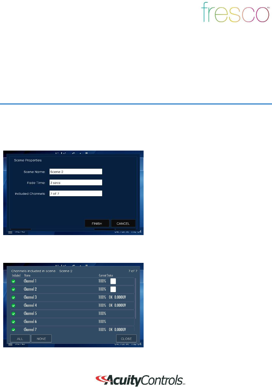
Overview
Each fresco station supports up to 36 lighting scenes. Scenes can made up of multiple lighting
channels,
1. Create a new
SCENE NA
ME
2. Set the transition time of the scene wi
th
FADE
TIME
3. Select
INCLUDED CHANNELS
that
allow specific lighting channels to
be
included/excluded within the
scene
1. Choose which lighting channels will
be
included within the new
scene
2. When finished press
CLOSE

9
Home Screen Menu
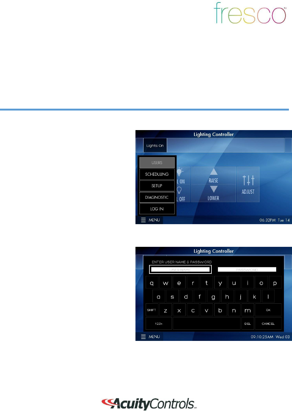
Overview
Menu provides access to system settings. Setup user profiles and access control,
system
configuration, and hardware
setup
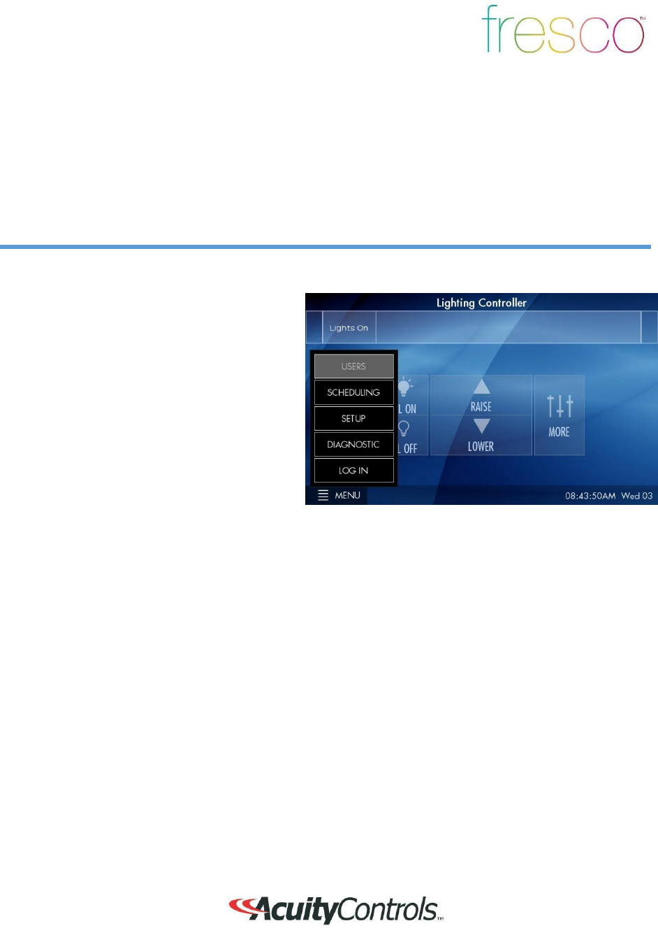
USERS
establishes the profiles used fo
r
secured system access
SCHEDULING
is currently not
implemented
in this firmware
version
SETUP
accesses system configuration
settings
DIAGNOSTIC
displays system technical data
LOG IN
to access system controls as setup
within
USERS
10
Menu>Users
Overview
User profiles can be setup to establish secured access to system
controls
1.
LOG IN
to access system control and
setup
2.
If any buttons within the
MENU
are
“greyed out” it indicates limited
syste
m
access
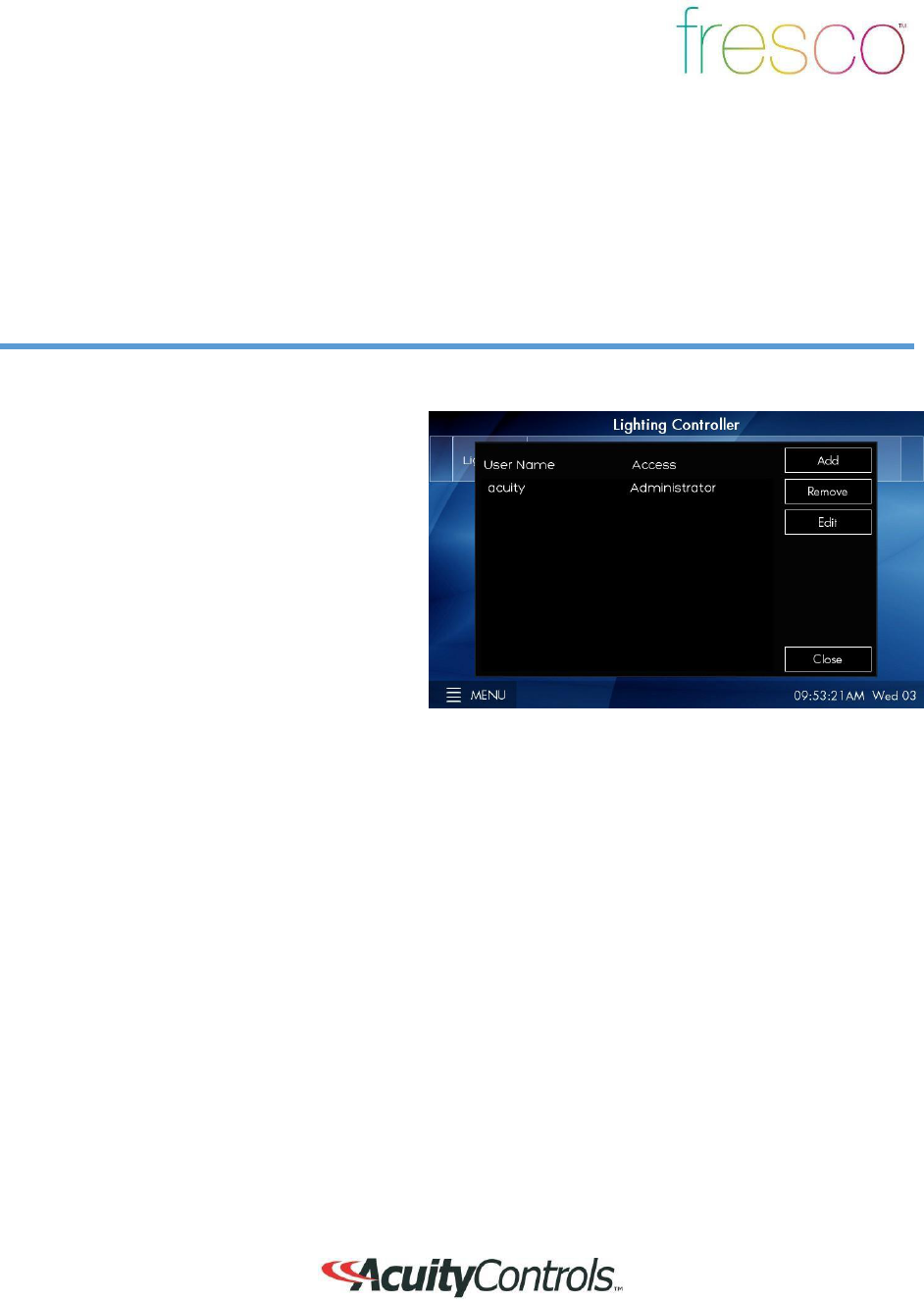
1. Default administrator username is
ACUITY
and password is
1234
2. Once logged in as administrator return to
MENU>USERS
to setup user
profiles
11
Menu>Users (continued)
Overview
User profiles can be setup to establish secured access to system
controls
1.
3 system access profiles are capable fo
r
setup
A.
Administrator
- Full system
access
to control and configuration.
Allo
ws
system profiles to be created
B.
Configure
- Full system access to
control and configuration
C.
Operate-
Access to
lighting
controls only. No ability to
create/modify scenes or
access
system configuration. Login is
required to access fresco
station
2.
ADD
additional profiles for
system
access
3. REMOVE
a user from the
system
4. EDIT
an existing profile

12
Menu>Scheduling and
Di
agnostic
Overview
Scheduling stores system time clock control and scheduled lighting events. Diagnostic
accesses
system technical data that is used for troubleshooting system
perfo
rm
ance
1.
Setting up
SCHEDULING
from
the
station is not currently supported.
All
schedules must be imported using the
Fresco Studio PC
tool
2.
DIAGNOSITC i
s only needed fo
r
reference when needing to troubleshoot
system perfo
rm
ance
13
Menu>Setup
Overview
Setup accesses system configuration
1.
SETUP
allows access to
system
configuration for:
A. System firmware
B. Screen adjustments
C. Network IP
settings
D. Lighting channels
E. nLight devices
F. DMX
fixtures
G. Lighting groups

14
Setup>About
Overview
System information including device serial number, operating firmware, network settings,
and
system reset
1. Fresco firmware
version
2. Station serial
numbe
r
3. Network/IP settings
4. nLight firmware
version
5. SET TIME
sets date and time for
station
6.
RESET
is for system reboot which
does
not erase any stored system data

15
Setup>Screen
Overview
Modify screen settings and display behavior
1.
The screen behavior can be set to react
in 3 steps when the room is active.
These settings can be set to a timeframe
(hours, minutes, seconds, or
never)
1.
First the
SCREEN TIMEOUT
IN
will send the display to a
logo
screen
2.
Next the
BACKLIGHT DIM IN
will
dim the logo screen
3. Finally the screen will go dark wi
th
BACKLIGHT OFF
I
N
2.
BACKLIGHT INTENSITY
adjust
the
overall intensity of the screen du
ri
ng
normal
use
3.
PROXIMITY SENSITIVITY
adjust the
sensitivity of the station IR sensor
that
awakes the station when the screen is
dark
4.
SHOW
buttons display control buttons on
the home screen for 3
rd
party
system
control. These are not cu
rr
ently
supported
5.
START ON “LIGHTS ON” PAGE
wil
l
make this page the primary screen
fo
r
turning lights on in the
space
6.
SHOW LOGO PAGE
will display if
the
screen is setup to timeout.
DEF
AU
LTS
sets all screen behavior settings to
factory defaults
16
Setup>Controlle
r
Overview
Setup station and network settings
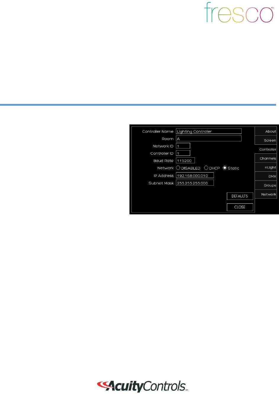
1.
CONTROLLER NAME
gives the
station
a unique name. Press the text box to
access keyboard
2.
ROOM
defines the single space that
accommodates the connected devices.
Up to 8 individual rooms can be setup to
be stand alone and also joined
(r
oom
linking
)
3.
NETWORK ID
is the local area Fresco
network. This value should not be
changed
4. CONTROLLER ID
is the Fresco
station
number on the network
5. BAUD RATE
is the data transfer
rate.
This should not be changed
6.
NETWORK
settings are used
when
accessing the station from an IP network
7.
IP ADDRESS/SUBNET MASK
values
can be modified based on IP network
configuration
8.
DEFAULTS
sends all network
settings
back to factory default

17
Setup>Channels
Overview
Lighting channels are used to control the behavior of lighting devices. A lighting channel
corresponds to the control slider. Up to 36 lighting channels can be assigned to a single fresco
station
1.
Create a new lighting channel
by
pressing
(+)
next to the channel location
1. Create a name for the channel that wi
ll
appear above the channel slider
2. Determine the type of
CONTROL
to
be
ZONE, GROUP,
or
NONE
1.
A
ZONE
can be a single or multiple
fixture controlled togethe
r
2.
GROUP
is more than one
ZONE
of
lighting controlled togethe
r
3. NONE
disables the channel slide
r
.
18
Setup>Channels (continued)
Overview
Lighting channels are used to control the behavior of lighting devices. A lighting channel
corresponds to the control slider. Up to 36 lighting channels can be assigned and displayed on a
single fresco
station
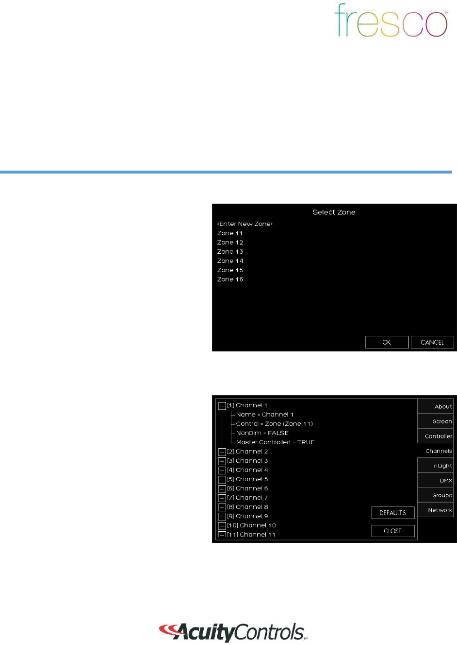
1.
Choose the
ZONE
that the channel
wi
ll
control. Choose an existing zone or
add
a new
zone
2.
There are 100 available zones available
on each fresco station, but you can only
have a maximum of 36 channel sliders.
This is intended for additional
devices
that need to be controlled by the system
without controlling them manually from
the station
1.
Choose if you want the
CHANNEL
to
be
NONDIM
.
FALSE
will provide the
0-100
intensity slider.
TRUE
will provide
an
ON/OFF toggle
2.
MASTER CONTROL
allows the
home
page raise/lower buttons to control
the
channel.
19
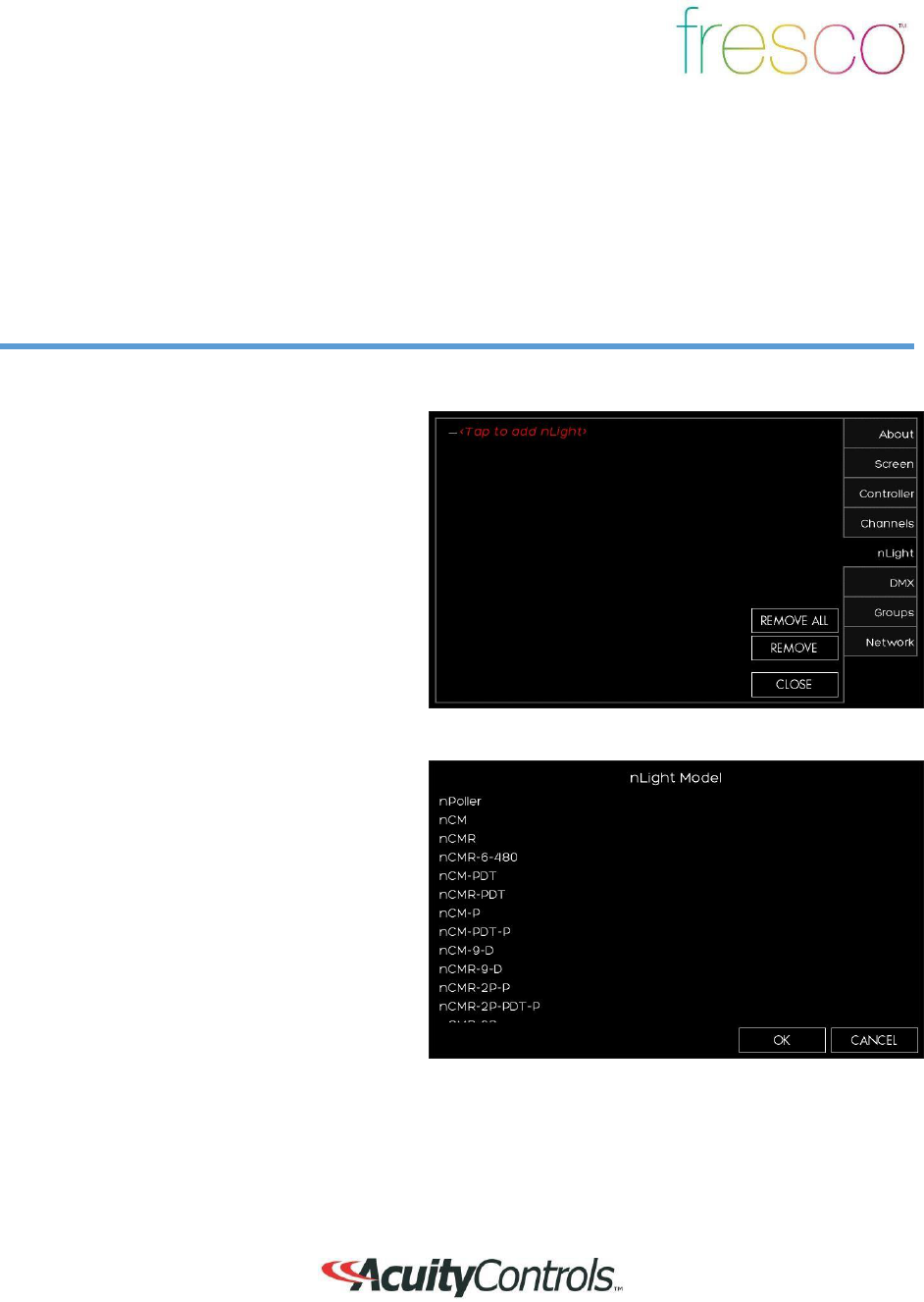
Setup>nLight
®
Overview
Add up to 128 supported nLight devices to each fresco station for
control
1.
If you have nLight devices a
lr
eady
connected to the station they will
appea
r
here
2.
If you need to manually add devices
press <Tap to add nLight>
devices
1.
After pressing <Tap to add nLight> a list
of supported nLight devices will
display
2. Select the device that you want to
add
20
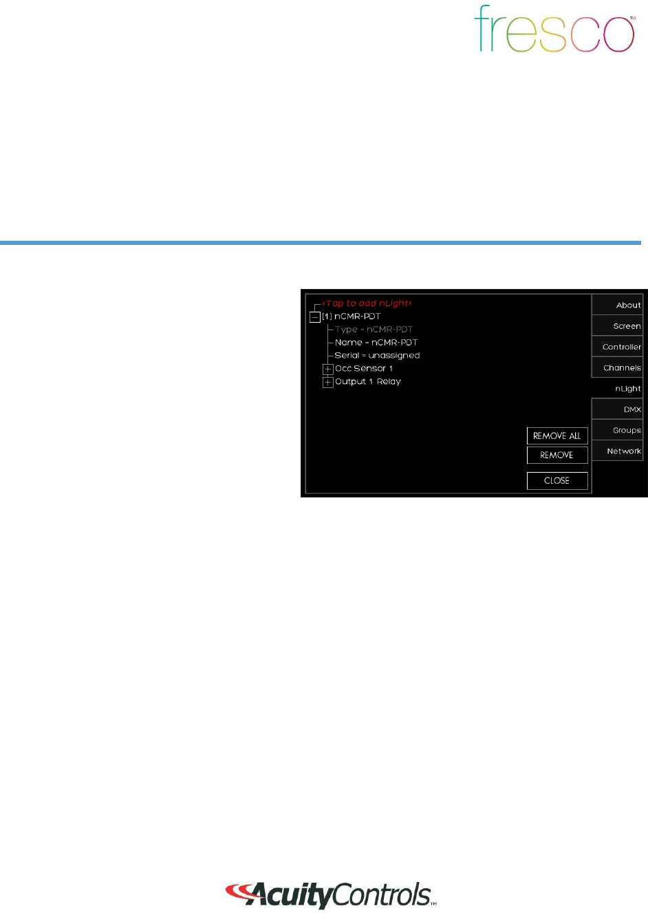
Setup>nLight® (continued)
Overview
Add up to 128 supported nLight devices to each fresco station for
control
1.
If the nLight device was auto identified o
r
you manually entered it you now need to
set it up
*
2.
Press the
(+)
next to the device to
expand the device settings
3. You can change the
NAME
of the
device
4. SERIAL
should be populated already.
If
it is not press
UNASSIGNED
and
choose
it from the list of available serial
numbers
that match the device
*TIP for UNKNOWN
devices
If the station auto discovers an nLight
device and appears as
UNK
NOWN,
REMOVE the device and manually
ente
r
the
device
21
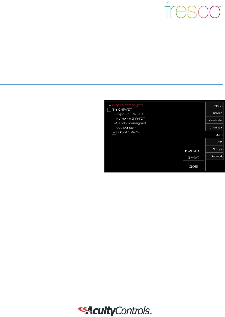
Setup>nLight® (continued)
Overview
Add up to 128 supported nLight devices to each fresco station for
control
1.
Depending on the device it now needs to
be configured for control. Press the
(+)
to
setup the control for the
device
2. Sensors/Wall
Stations/Po
wer
Packs/Embedded Fixtures Devices
1.
Change the
NAME
of the
nLight
device if desired
2.
Choose the type of
CONTROL
it wi
ll
affect
(Group/Zone/Scene/Channel/None
)
3.
MODE
for sensors only will
change
the setting to (Auto On/Manual Off
or Manual On/Auto Off)
4.
TIMEOUT
will adjust device
timeout
setting
5.
OUTPUT
sets what the
relay/dimmer will
control
6.
Change the
NAME
of the
device
output if desired
7. Choose what
ZONE
it will
control
8.
THRESHOLD
changes when the
relay will get switched on. This wi
ll
not matter when you assign this to a
non-dim channel. You are best to
leave this field unchanged
9. LOW SET/HIGH SET
are
adjustable trim settings for
dimming
wall stations/po
wer
packs/embedded fixture devices

22
Setup>DMX
Overview
One universe (512 channels) of DMX allows control of DMX/RDM
fixtures
1.
If you have RDM capable DMX
devices
already connected to the station they wi
ll
appear here
2.
If you need to manually add
DM
X
devices press <Tap to add DM
X>
devices
1.
After pressing <Tap to add DMX>
choose
the DMX fixture type that best
matches
the profile
required
2. Choose the DMX start
address
3.
Next select the
ZONE
that it will
be
assigned to
4.
If you know the exact fixture ID
listed
within the Horizon DMX fixture library
(provided upon request) choose
OTHER
and enter the fixture ID and enter
the
DMX start address and zone output
fo
r
assignment
23
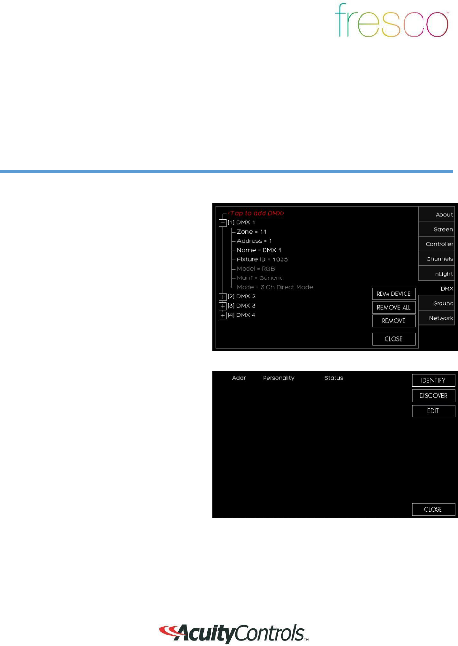
Setup>DMX (continued)
Overview
One universe (512 channels) of DMX for control of DMX/RDM
fixtures
1.
If the DMX fixture was auto identified
o
r
you manually entered it you now need to
set it up
2.
Press the
(+)
next to the device to
expand the device settings
3.
Verify the
ZONE
assignment and
co
rr
ect
start ADDRESS is correct. Make
the
changes if necessary
4.
RDM responding fixtures can be
setup
by pressing
RDM
DEVICE
1. DISCOVER
will force a DMX signal to
search for all RDM discoverable fixtures
2.
After the search has completed a list
of
fixtures will display in this
list
3.
IDENTIFY
will locate the fixture (flash to
find
)
4.
EDIT
will allow the personality of
the
fixture to be changed if available
24
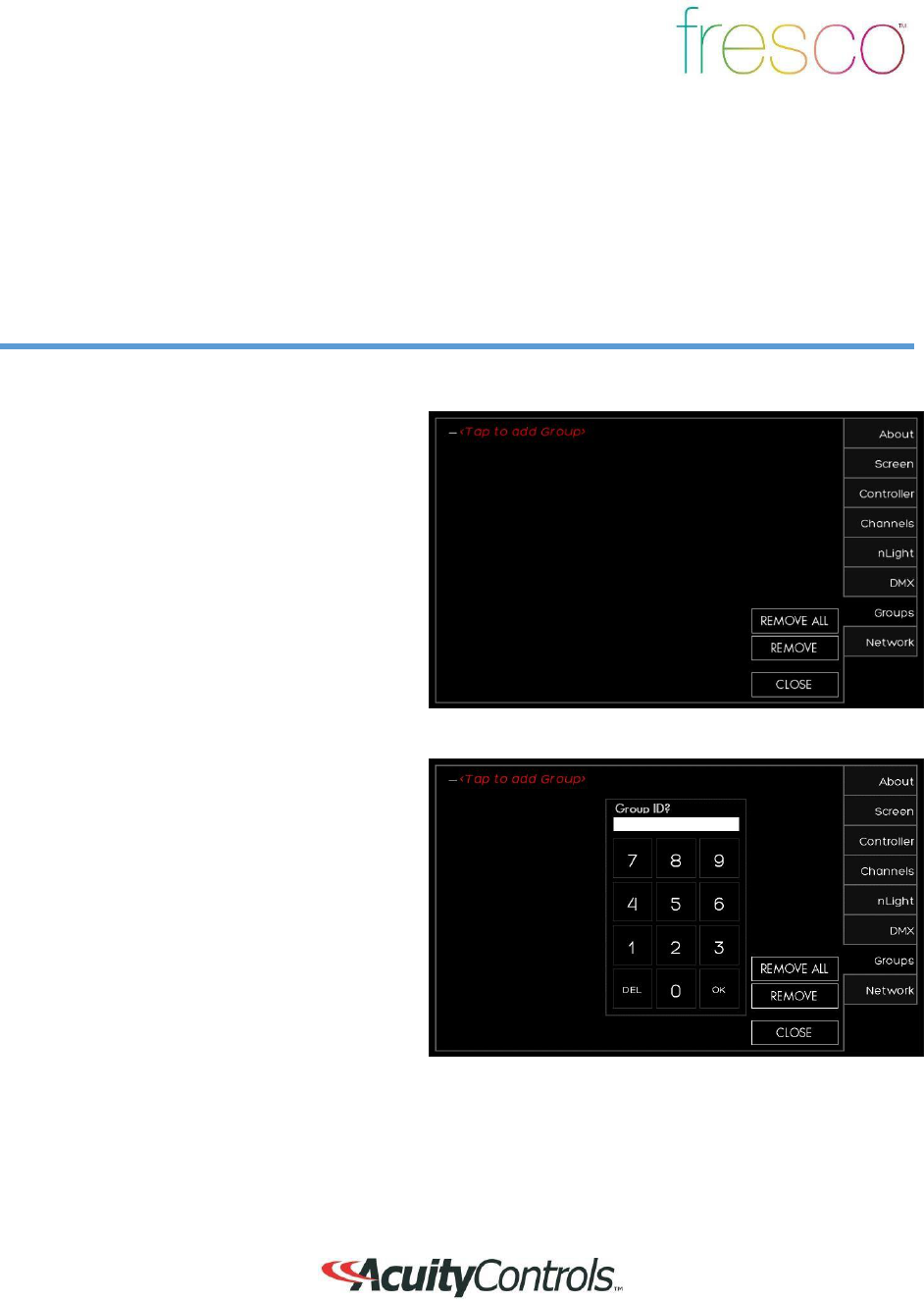
Setup>Groups (continued)
Overview
Multiple lighting zones can be linked together in groups for joint
control
1.
Create a new group by pressing <Tap to
add Group>
1.
Set a new
GROUP ID
, start at 1 to
keep
it simple and easy to manage
2.
You can create up to 100 groups
of
lighting
25
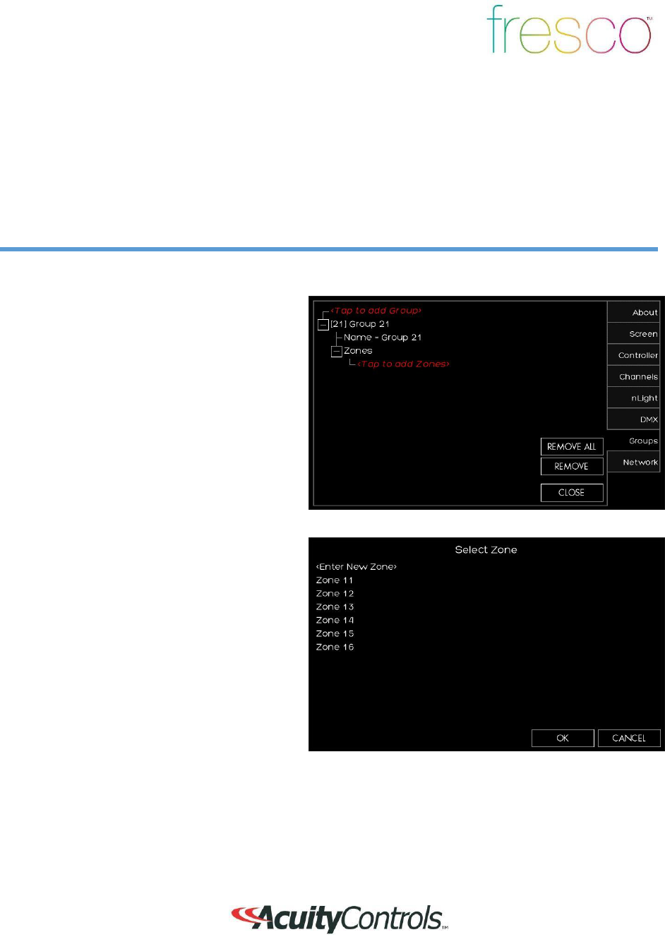
Setup>Groups
Overview
Multiple lighting zones can be linked together in groups for joint
control
1. Press
(+)
to expand the group settings
2.
Change the group
NAME
to make it
easier to manage by
pressing
NAME=GROUP #
3.
Press
(+)
to expand the
ZONES
that
need to be added to the group
1.
Select the zones that need to be added
to the group. This are existing zones, o
r
a new zone can be setup

26
Setup>Network
Overview
Network allows the setup and configuration for future fresco system
devices
1.
There is no current product supported
fo
r
this system feature at this time

27
FCC Guidelines
This equipment has been tested and found to comply with the limits for a Class A digital
device,
pursuant to part 15 of the FCC Rules. These limits are designed to provide
reasonable
protection against harmful interference when the equipment is operated in a
commercial
environment. This equipment generates, uses, and can radiate radio frequency energy and, if
not installed and used in accordance with the instruction manual, may cause
ha
rm
ful
interference to radio communications. Operation of this equipment in a residential area is likely
to cause harmful interference in which case the user will be required to correct the
interference
at his own
expense
RF Exposure Limit Warning
To comply with FCC’s RF exposure limits for general population /
uncontro
ll
ed
exposure, the antenna(s) used for this transmitter must be installed to provide a
separation distance of at least 20cm from all persons and must not be co
-
located
or operating in conjunction with any other antenna or
transmitte
r
.
This Device complies with Part 15 of the FCC Rules. Operation is subject to
the
Following
Conditions:
1. This device may not cause harmful interference,
and
2. This device must accept any interference received, including interference that
may cause undesired operation.
Warning (Part
15.21
)
Changes or modifications not expressly approved by the party responsible
fo
r
compliance could void the user’s authority to operate the
equipment.
Only the following types of antennas with an equal or lesser gain may be used with
this
equipment:
PCB, Trace Antenna, 5.3 db
Gain

28
IC Guidelines
This device complies with Industry Canada license-exempt RSS
standard(s). Operation is subject to the following two
conditions:
(1) this device may not cause interference, and (2) this device must accept
any
interference, including interference that may cause undesired operation of the
device.
Le présent appareil est conforme aux CNR d’Industrie Canada
applicablesaux
appareils radio exempts de licence.L’exploitation est autorisée aux
deux
conditions suivantes :
(1) l’appareil nedoit pas produire de brouillage, et (2)l’utilisateur de l’appareil
doit
accepter tout brouillage radio électrique subi, même si le brouillage
est
susceptible d’encompromettre le
fonctionnement.
Under Industry Canada regulations, this radio transmitter may only operate using
an
antenna of a type and maximum (or lesser) gain approved for the transmitter by
Industry
Canada. To reduce potential radio interference to other users, the antenna type and its
gain
should be so chosen that the equivalent isotropically radiated power (e.i.r.p.) is not
more
than that necessary for successful
communication.
Conformémentà la réglementationd'IndustrieCanada, le présentémetteurradio
peutfonctionneravec uneantenned'un type et d'un gain maximal (ouinférieur)
approuvépou
r
l'émetteurpar IndustrieCanada. Dansle but de réduireles ri
squesde
brouillageradioélectriqueà l'intentiondes autresutilisateurs, ilfautchoisirle type
d'antenneet
son gain de sortequela puissance isotroperayonnéeéquivalente(p.i.r.e.) ne
dépassepas
l'intensiténécessaireà l'établissementd'unecommunication satisfaisante.