Adams Rite 80 0180 460_M 4550 MS Deadlock Lever Installation Instructions 460 M
User Manual: Adams Rite 4550 MS Deadlock Lever Installation Instructions Installation Instructions
Open the PDF directly: View PDF ![]() .
.
Page Count: 2
www.adamsrite.com
Phone: 800-626-7590
800-872-3267
Fax: 866-582-4641
800-232-7329
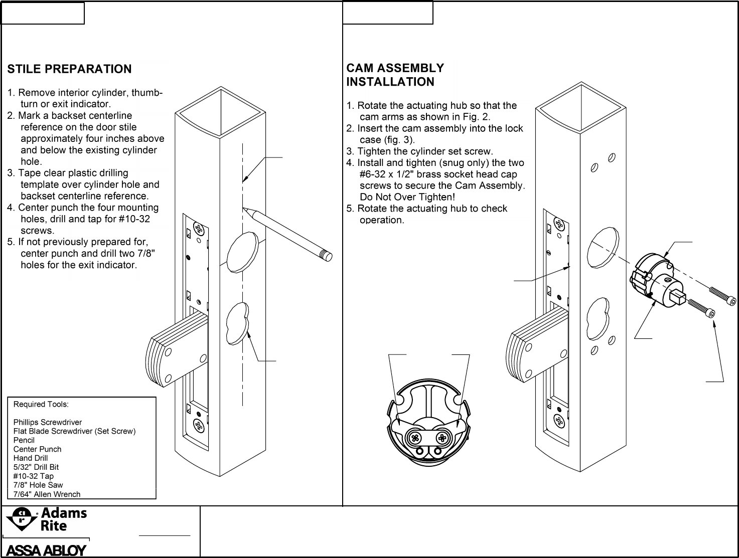
CAM PLUG
ASSEMBLY
ACTUATING
HUB
BRASS
SOCKET HEAD
CAP SCREW
CYLINDER SET SCREW
CAM ARMS
FIG. 2
NOTE: Not compatible
with 7/8" backset locks
FIG. 1
FIG. 3
BACKSET
C
L
EXIT INDICATOR
PREPARATION
STEP 1 STEP 2
P. NGUYEN
B
11955D
Rev.
Date: 76/20/12
INSTALLATION INSTRUCTIONS
Appvd: MP
Ecn
4550 SERIES
80-0180-460
M
PAGE 1 OF 2

www.adamsrite.com
Phone: 800-626-7590
800-872-3267
Fax: 866-582-4641
800-232-7329
LEVER ASSEMBLY
Lever may stick if
the lever assembly
is mis-located.
loosen mounting
screws and move
the assembly
around to find the
best location, then
secure.
ACTUATING HUB IN
THE 12 O'CLOCK POSITION
FIG. 5
#1 EXIT INDICATOR
SPRING 1-55/64"
#10-32 x 3/4" Phillips
Pan Head Screws
FIG.
#10-32 x 7/16" Phillips
Flat Head Mach. Screw
(LH OR LHR SHOWN)
FIG. 6
STOP PLATE
DRIVE HUB
SPRING
RETAINER
BUSHING
PAN HEAD
MACHINE
SCREWS
FOR 2 AND 3 POINT SYSTEMS:
USE EXIT INDICATOR PIN AND
#2 EXIT INDICATOR SPRING 37/64"
FIG. 7
TOP LEG
STAND-OFF
POSITION INSIDE BEND
AROUND STAND OFF
BOTTOM LEG
NOTE: Not compatible
with 7/8" backset locks
S
T
E
P
3
11955D
Rev.
Date: 07/20/12
INSTALLATION INSTRUCTIONS
Appvd: MP
Ecn
4550 SERIES
80-0180-460
M
PAGE 2 OF 2
