Adaptiv Technologies A-01-01 Radar Detector TPX main console User Manual
Adaptiv Technologies, LLC Radar Detector TPX main console Users Manual
Users Manual
1
Radar detector TPX main console
MODEL: A-01-01
FCC ID: VWV-A-01-01
Adaptiv Technologies, LLC
2
z Notice.
The contents of this manual are subject to change without notice.
Changes or modifications not expressly approved by the party responsible for
compliance could void the user's authority to operate the equipment.
CONTENTS
Ⅰ. MODEL FEATURES AND CONTROLS
• Radar Detection System.
• ALL Band Protection .
Ⅱ. ACCESSORIES INCLUDED WITH RADAR DETECTOR
• Owner’s Manual
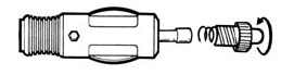
• Power Cord & Power Din Cable
• Mounting kit
• Hook & Loop Fasteners
• Spare Fuse
• Wireless Headset
Ⅲ. MOUNTING INSTALLATION
• Windshield Mounting
• Dash Board Mounting
• Power connection
Ⅳ. OPERATION GUIDE
• Power on & Self-Test
• Feature Engaged Confirmation
• Mute Mode(Alert off)
• City Mode
• Mode Menu
• Real tone Alert
• Speed Radar Visual /Audio Alerts
• Laser Visual /Audio Alerts
• Wireless Headset Visual/Audio Alerts
• Memory Retention
V. TROUBLESHOOTING GUIDE
• Factory setting
VI. SPEED MONITORING DEVICES
• Radar speed gun
• Laser speed gun
3
VII. MAINTENANCE
• Care and Maintenance
• Fuse Replacement
VIII. SPECIFICATIONS
• General
• Laser Detector
• Radar Detector
• Transmitter Freqency(Tx)
• Wirelwss HEADSET(Rx)
Ⅰ. MODEL FEATURES AND CONTROLS
• Real Tone Alert
• X, K, Ka Super Wideband Detection
• All Laser Detection
• 360° Laser Detectability
• Instant – On/Pulsed Radar Alert
• Smart Text LCD Display
• User Programmable
• Memory Retention
• Signal Strength Meter
• Visual & Audible Alarms
• Electronic Power On/Off Switch with Volume Control
• External Jack for External Laser Censors
• Mute Mode
• City /City Nox Mode
4
1. Bracket Lock/Release Button – Easy lock/release of the mounting bracket.
2. Power Jack – Connection for the power cord and power cable ass’y.
3. Speaker – Provides distinct audio alarms for X, K, Ka band radar and laser.
4. Power Button – Turns unit on/off .
5. High Visibility Text Display – Provides distinct visual confirmation of signals
strength, signal band identification and indicates engaged modes of operation.
6. MUTE Button – Pressing MUTE during a radar/laser encounter silences audio alerts.
7. CITY Button – Reduces the annoyance of false alerts typically encountered in urban
driving areas.
8.Volume Control( +,- ) - Adjusts audio level
9. Laser Lens (Rear) – An integrated optical waveguide provides superior detection of
laser signals transmitted from behind
10. Laser Lens (Front) – High gain optical lens array provides increased
sensitivity and field of view for leading edge laser detection.
11. Radar Antenna – Compact, high-efficiency antenna receives radar
signals.
12. Mounting Bracket Location – Slot holds mounting bracket firmly.
13. EXT – Port for external laser censor connection
Ⅱ. ACCESSORIES INCLUDED WITH RADAR DETECTOR
• Owner’s Manual
• Power Cord & Power Din Cable
• Mounting kit
• Hook & Loop Fasteners
• Spare Fuse
• Wireless Headset
Ⅲ. MOUNTING INSTALLATION
• Windshield Mounting
• Dash Board Mounting
• Power connection
5
Ⅳ.OPERATION GUIDE
Buttons
• Buttons to have adequate tactile feel and size to be actuated while using riding gloves.
• Backlit - blue
• Button Functions:
o Button 1 (top right)- Volume Increase and Brightness Increase.
o Button 2 (bottom right) – Volume Decrease and Brightness Decrease
o Button 3 (top center) – Power On/Off.
o Button 4 –City/Highway and Volume / Brightness Mode
o Button 5 – Mute and Visual Indicator Intensity Off and backlights on/off.
“long” means about 2-3 sec
• Power on &Self test/
Press the Power Button for 2 seconds to turn the unit on or off
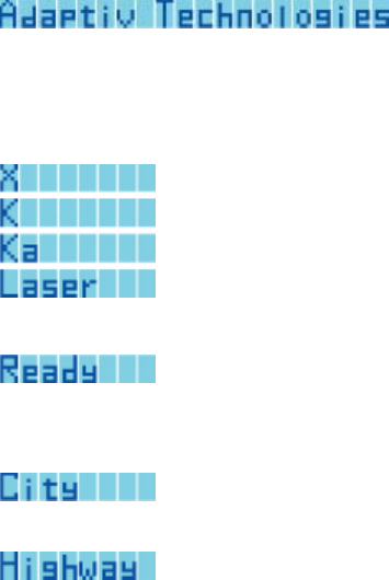
Start Up
“Adaptiv Technologies” will be scrolled across the LCD display, entering from the right
and exiting at the left, and it will scroll all the way through:
Then self test will start, where each band will be displayed accompanying its alerted
sound:
Then the display that the system is ready:
Then the unit will display the City/Highway Mode that the unit is currently in, either:
or
and the system will remember the last City/Highway setting each time it is turned off.
“City” or “Highway” will be the default display on the LCD when no other information
needs to be conveyed.

6
Main Unit Functions
When radar or laser signals are detected, the detected band and its strength will be
displayed, along with its distinct sound alert.
Power Button
Press the Power Button for 2 seconds to turn the unit on or off.
Mode Button (upper left button)
For City/Highway Mode, each time this button is pressed it will toggle between “City” and
“Highway” modes, and the display will display the mode setting selected. A beep will be
emitted with each mode change.
For Peripheral Control Mode, each time this button is pressed for 2 or more seconds it will
toggle between “Headset Volume Control” (Vol), and “Visual Alert Brightness Control”
(LED) with the following displays:
The display for the toggled Peripheral Control Mode will only be displayed on the LCD for
2 seconds, then the display will revert back to either “City” or “Highway”, unless a signal
is being detected.
The Peripheral Control Mode affects how the “Up” and “Down” buttons function, which
will be explained later in this document.
Alert Off/Dim Button (lower left button)
If a radar or laser signal is detected, pressing this button will temporarily mute all audio
alerts (main unit and headset) and stop the LEDs on the Visual Alert from flashing. Audio
and visual alerts will be stopped for the duration of the detected signal and any new
signals detected within the next seconds. When this button is pressed,

7
will be displayed for 1 second, and the detected radar or laser signal will return to the LCD
display.
When this button is pressed for 2 or more seconds, it will toggle the backlight on the Main
Unit buttons on/off.
Up and Down Buttons (upper and lower right buttons)
The “Up” and “Down” buttons control the volume of the Main Unit and the Headset, and
the LED brightness of the Visual Alert. When each is pressed for 1 or more seconds, the
increase or decrease in the volume/brightness will increase or decrease continuously until
the maximum or minimum volume level is reached. The system will remember the last
volume setting each time it is turned on, except for the Visual Alert, where auto-setting is
the default (explained below).
When “Headset Control Mode” is selected, the “Up” and “Down” buttons control the
volume on the Main Unit and the Headset. For each level the volume is raised/lowered,
the Main Unit and the Headset will emit a corresponding volume. The display is as
follows:
The Main Unit has a photo-sensor and it automatically controls the brightness setting on
the Visual Alert. The auto-setting is the default setting on the Visual Alert each time the
unit is turned on. However, it can be over-ridden by the user with a push of the “Up” or
the “Down” button if “Visual Alert Control Mode” is selected. When “Visual Alert Control
Mode” is selected, the “Up” and “Down” buttons control the LED brightness on the Visual
Alert. Each time the button is pressed, the Main Unit will emit a beep and the Visual Alert
will double flash a corresponding brightness. The auto-setting function can be turned
back on by the user by select the “lowest” setting on the “Down” button. The display is
as follows:
8
Other:Tx Opertion
The Main Units must operate properly and not interfere with each other when multiple units
are being used in the same vicinity (>2m).
The Main Unit will emit a beep every time a button is pressed (except Alert Off).
The transmitter format is system data /band ID and signal strength data .
The Main unit only operation transmitter (418Mhz):
*Main Unit function press operation.exmple mode chang and volum up&down.(Manul Tx)
* When Main Unit radar/laser signal detector is Tx formatted transmitter.(Semi Auto)
Wireless Headset:Rx Opertion
The Power Button on the Headset has an LED backlight. It will flash once every 3
seconds when it is turned on. It will have a double flash every 3 seconds when it is in
communication with the Main Unit. The Headset will have an auto-shut off capability if it
is not in communication with the Main Unit after 15 minutes.
The Headset will beep each time a function button on the Main Unit is pressed.
The Headset will emit the exact same beeps as the Main Unit.
The Headset must not transmit or receive interference from other radar detectors or
Headsets at distances greater than or equal to 2 meters.
Visual Alert
The Visual Alert will flash each time a function button on the Main Unit is pressed.
LED Intensity to be adjustable from Main Unit buttons as well as photo sensor.
Flash frequency to correlate with signal strength.
Memory Retention
Electronically remembers all your own settings for a certain period of time after power-off.
V. TROUBLESHOOTING GUIDE
PROBLEM: No display or audio.
• Check fuse in the plug and replace if necessary with a 2 amp 3AG type.
• Check fuse for lighter socket; replace if necessary.
• Make sure lighter socket is clean.
PROBLEM: Unit alarms when vehicle hits bumps.
9
• Check for loose lighter socket; tighten and clean.
• Check connections at both ends of power cord. Substitute another cord to determine if
cord is defective. Return defective cord to the factory.
PROBLEM: Unit alarms when using vehicle equipment or electrical accessories
(brakes, power mirrors/windows, directionals, horn, etc.).
• Vehicle’s electrical system, including battery and alternator, may have electrical noise.
Install a filter capacitor (470mfd. 25 volt or larger capacitance value) on the back of the
lighter socket.
Factory setting
All user features can be reset to factory settings. Please follow below steps for reset.
1. Unplug Power Cord from unit
2. Press and hold Power and Mute/City Key.
3. Plug Power Cord into unit.
4. Wait for 2 beeps.
5. Release Power and Mute button. Unit is now reset
- Factory reset -
• Highway Mode On.
• Dim/Dark Mode to full illumination of display.
VI. SPEED MONITORING DEVICES
Radar speed gun
A radar gun operates by transmitting radio waves at certain frequencies which reflect off
objects and are then picked up by the radar gun’s receiving section. When a radar beam
reflects off a moving target, a measurable frequency shift occurs. The radar unit converts
this shift into miles per hour to determine your vehicle’s speed.
Laser speed gun
It’s well documented that many radar guns cannot reliably provide the speed of a targeted
vehicle that is traveling in a group of vehicles. In contrast, a laser gun can target a
specific vehicle out of a line of traffic and determine its speed.
The advantage of laser over radar in terms of target identification is the result of the laser
gun’s narrow beam. A radar transmission can cover more than a four-lane highway at a
distance of 1,000 feet, compared with a laser transmission which covers about 6 feet at
the same distance.
For best protection, keep these points in mind:
• Because your vehicle’s license plate or headlights are the laser gun’s primary targets,
mounting your detector on the dashboard can improve laser detection at short range.
• Do not follow closely behind any vehicle you cannot see through. If you can’t see past a
vehicle ahead of you, chances are your detector won’t either.
• The receiving range of your laser detector will not be the
same as a radar detector. Laser guns are most often used at
short range
10
VII. MAINTENANCE
Care And Maintenance
During the summer months, avoid prolonged exposure to direct sunlight by removing your
unit from the dash when your vehicle is parked for an extended period of time.
Do not spray water, cleaners or polishes directly onto the unit. The spray may penetrate
through the openings and damage the unit. Also, do not use any abrasive cleaners on the
unit’s exterior.
Fuse Replacement
The lighter socket plug is equipped with a replaceable 2 amp 3AG fuse located behind the
silver tip. To replace the fuse, carefully unscrew the tip of the plug. (IMPORTANT: Unscrew
slowly. The tip contains a spring which may fly out when disassembling.) Insert the new
fuse with the spring and screw on the tip.
With use, screw cap on plug may loosen. Retighten occasionally.
VIII. SPECIFICATIONS
• General
Dimensions: 65mm(W)x 118mm(L) x 42mm(H)
Weight: 185 g
Power Requirement: CAR Battery DC 12V
Temperature Range: Operating -20°C to +80°C
Storage -40°C to +100°C
• Laser Detector
Receiver Type Pulse Laser Signal Receiver
Sensor Front End Convex Condenser Lens
Detector Type Pulse Width Discriminator
Receiver Bandwidth 30 MHz
Spectral Response 800- 1100 nm
• Radar Detector
Receiver Type Double Conversion Superheterodyne
Detector Type Scanning Frequency Discriminator
Antenna Type Linear Polarization
Frequency of 10.525 GHz ± 50 MHz (X Band)
Operation 24.150 GHz ± 100 MHz (K Band)
34.700 GHz ± 1300 MHz (Ka Band)
11
• Transmitter Freqency(Tx)
Transmitter Manual Tx & Auto
418.00 MHz ± 75 KHz
Moudulation ASK(Amplitude shift keying)
Transmitter used in device SAW(surface acoustic wave) RESONATOR
NDR4047
Tolerance of transmission frequency ± 20 ppm
Modulation contents Digital data
Data rate 16Bit/70ms
• Wirelwss HEADSET(Rx)
Receiver Type Oscillator conversion
Detector Type Scanning Frequency Discriminator
Antenna Type Linear Polarization
Frequency of Operation 418.00 MHz ± 5 MHz
Power Requirement 3V DC Battery (CR-2450)