Adaptrum ACRS10 TV Band Device User Manual acrs10 professional installer manual
Adaptrum, Inc TV Band Device acrs10 professional installer manual
Adaptrum >
Contents
- 1. acrs10_user_manual
- 2. acrs10_professional_installer_manual
- 3. Manual
- 4. Professional Installer Manual
- 5. User Manual
- 6. revised professional_installer
- 7. revised user manual
acrs10_professional_installer_manual

1
ACRS 1.0 Professional Installer Manual

2
FCC Regulatory Information
This device complies with part 15 of the FCC Rules. Operation is subject to the following two
conditions: (1) This device may not cause harmful interference, and (2) this device must accept any
interference received, including interference that may cause undesired operation.
Any changes or modifications not expressly approved by the party responsible for compliance could
void the user’s authority to operate the equipment.
Part 15 TV Band Device Notice
This equipment has been tested and found to comply with the rules for TV bands devices, pursuant to
part 15 of the FCC rules. These rules are designed to provide reasonable protection against harmful
interference. This equipment generates, uses and can radiate radio frequency energy and, if not
installed and used in accordance with the instructions, may cause harmful interference to radio
communications. If this equipment does cause harmful interference to radio or television reception,
which can be determined by turning the equipment off and on, the user is encouraged to try to
correct the interference by one or more of the following measures:
(1) Reorient or relocate the receiving antenna.
(2) Increase the separation between the equipment and receiver.
(3) Connect the equipment into an outlet on a circuit different from that to which the receiver is
connected.
(4) Consult the manufacturer, dealer or an experienced radio/TV technician for help.
Caution: Exposure to Radio Frequency Radiation.
To comply with FCC RF exposure compliance requirements, for fixed configurations, a separation
distance of at least 40 cm must be maintained between the antenna of this device and all persons.
This device must not be co-located or operating in conjunction with any other antenna or transmitter.

3
Installation Package Content
Base Station Kit
The base station installation kit includes the following components:
• ACRS 1.0 radio and power cord
• Kathrein CL-1469B UHF-TV log-periodic antenna and cable
• Base station control PC
• Ethernet cables
• USB memory stick with software installation package
Client Station Kit
The client station installation kit includes the following components:
• ACRS 1.0 radio and power cord
• Kathrein CL-1469B UHF-TV log-periodic antenna and cable
• Client station control PC
• Ethernet cables
• Broadband router
• USB memory stick with software installation package

4
Hardware Installation
ACRS 1.0 is the first generation Adaptrum cognitive radio system covering spectrum bands from
400 MHz to 1 GHz. ACRS 1.0 is specifically designed to operate in the UHF TV Band (470 MHz – 698
MHz), as TV Band Devices compliant to the rules specified in CFR 47 Part 15 Subpart H. To be rules
compliant, ACRS 1.0 systems must operate as Fixed TV Band Devices and must be professionally
installed.
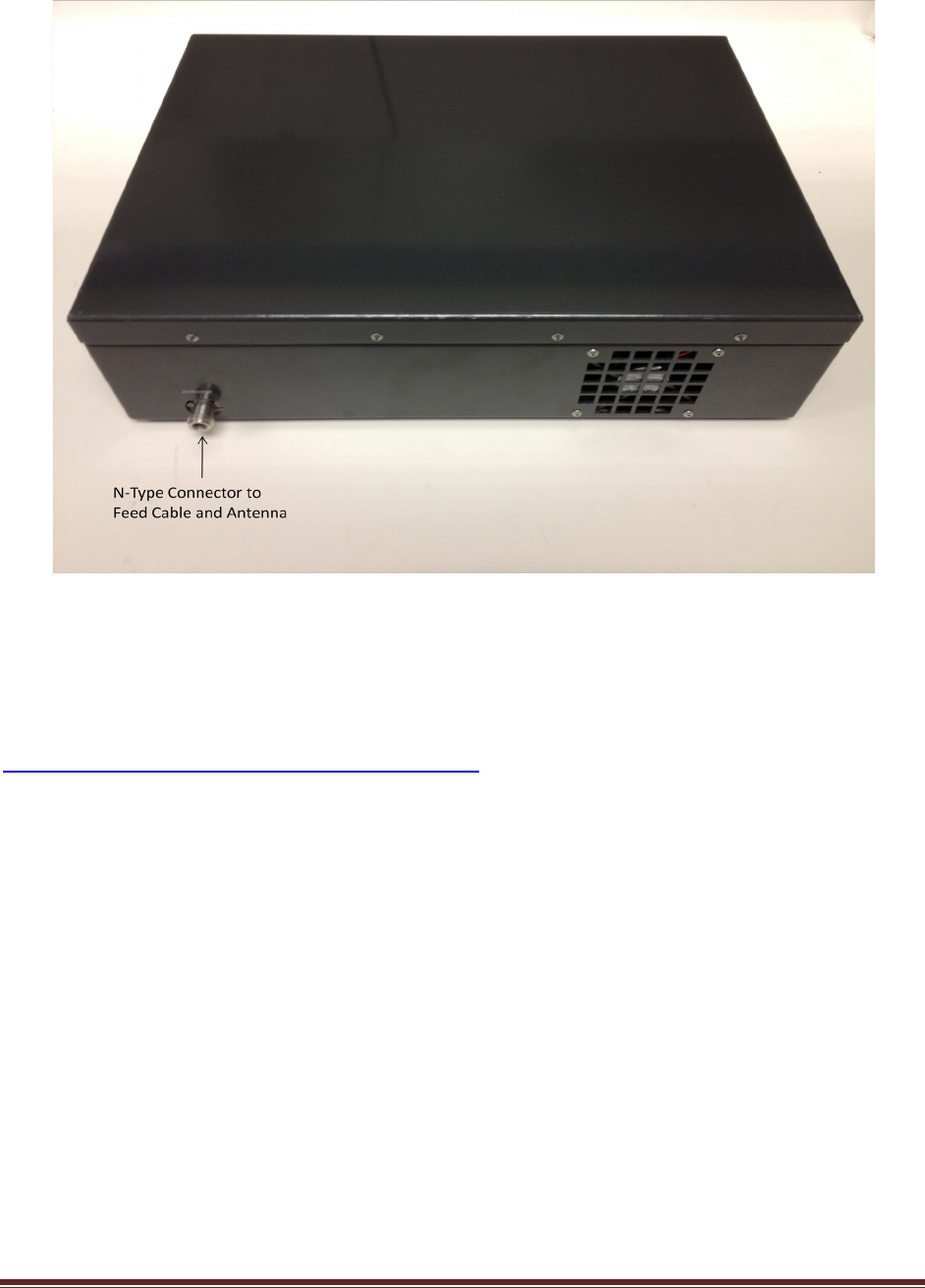
ACRS 1.0 radio unit is enclosed in a 2U size box whose front panel and back panel are shown in
the following pictures. Both the base station and the client station use the same radio unit.
5
ACRS 1.0 system has been authorized for use with the supplied Kathrein CL-1469B UHF-TV log-
period antenna. Only log-periodic antennas with a gain of 10.15 dBi or less can be used with the ACRS
1.0 system and no other types of antennas should be used. The log-periodic antenna used with the
ACRS 1.0 system must have well characterized gain. Antenna feed cable loss should also be
characterized. The datasheet of Kathrein CL-1469B UHF-TV log-periodic antenna can be found at
http://www.kathrein-scala.com/catalog/CL-1469B.pdf.
The installer must ensure that the antenna assembly meets the following requirement:
Antenna EIRP – Feed Cable Loss – Attenuator Setting = 7 dBi
Here the “Attenuator Setting” is a software programmable output attenuation setting for the radio
device that can be programmed at installation time (referring to Section “Post-Installation Setup” for
discussion on how to program the setting). As an example, when a 10 dBi EIRP antenna and a feed cable
with 1 dB loss are used, the “Attenuator Setting” must be programmed to:
Attenuator Setting = 10 dBi – 1 dB – 7 dBi = 2 dB
The “Attenuator Setting” programming must be done correctly during installation to ensure the
device is compliant with the CFR 47 Part 15 Subpart H rules.

6
ACRS 1.0
Base Radio
Feed Cable
Antenna
Base Control
PC
Ethernet
Internet
Ethernet
Base station installation diagram.
ACRS 1.0
Client Radio
Feed Cable
Antenna
Client Control
PC
Ethernet Broadband
Router
Ethernet
Ethernet/WiFi
Client
Devices
Client station installation diagram.
The above figures show the hardware installations at both the base station side and the client
station side to allow the client side networking devices to connect to the Internet through the TV
whitespace link between the base station and the client station.
For both the base station and the client station installations, the ACRS 1.0 radio N-type
connector is connected to the feed cable which is connected to the antenna. The Ethernet ports of the
base and client radios are connected to Ethernet ports on the base control PC and client control PC.
Both the base control PC and the client control PC have dual Ethernet ports. One of the Ethernet
port is connected to the radio. The second Ethernet port on the base control PC is connected to a router
or switch that connects to the Internet. The second Ethernet port on the client control PC is connected
to a broadband router or switch which connects to the client side networking devices.
Once the hardware installation is complete, follow the instructions in the following sections to
perform the software installation on the control PC. Note if an installed radio unit and control PC are
redeployed at a differently location, the installer must uninstall the old software and reinstall the
software on the control PC.
7
Software Installation
The USB memory stick comes with the package contains the software installer
“AdaptrumTVBDStationInstallerSetup.exe” for the base station software installation or
“AdaptrumTVBDClientInstallerSetup.exe” for the client station software installation. The software can
run on Windows XP or Windows 7. The following describes the installation process on a Windows 7 PC.
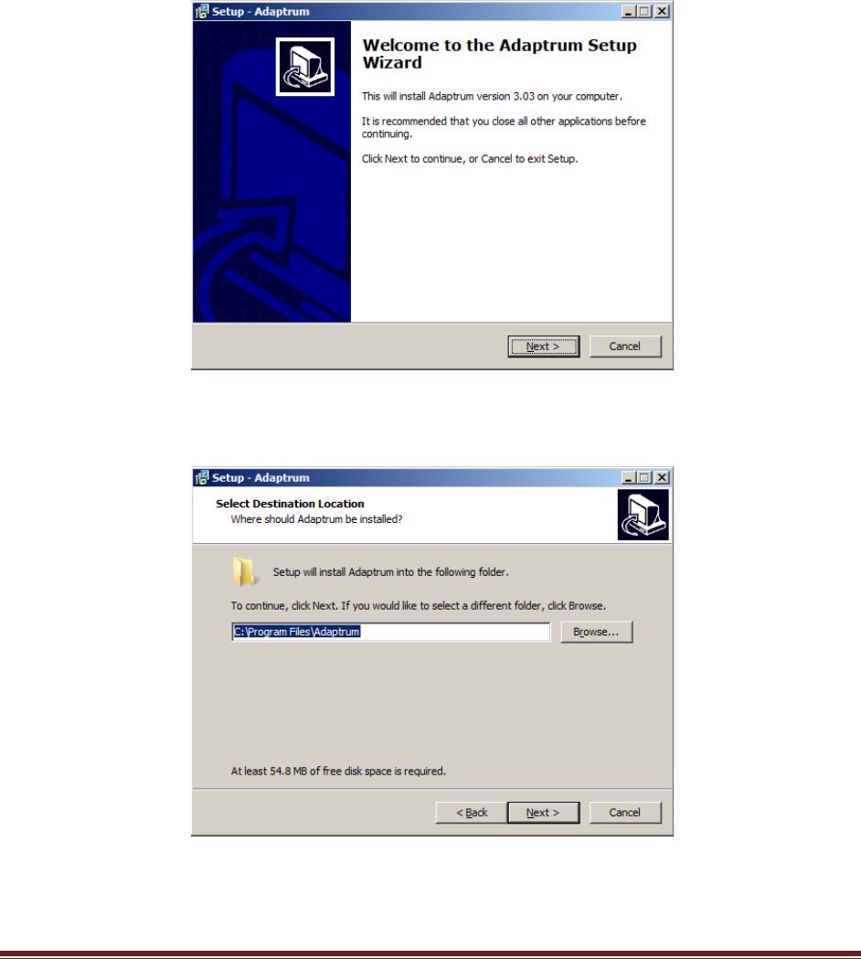
1) On the base control PC, double click the installer executable. The following set up program will
show up. Select “Next” to continue installation.
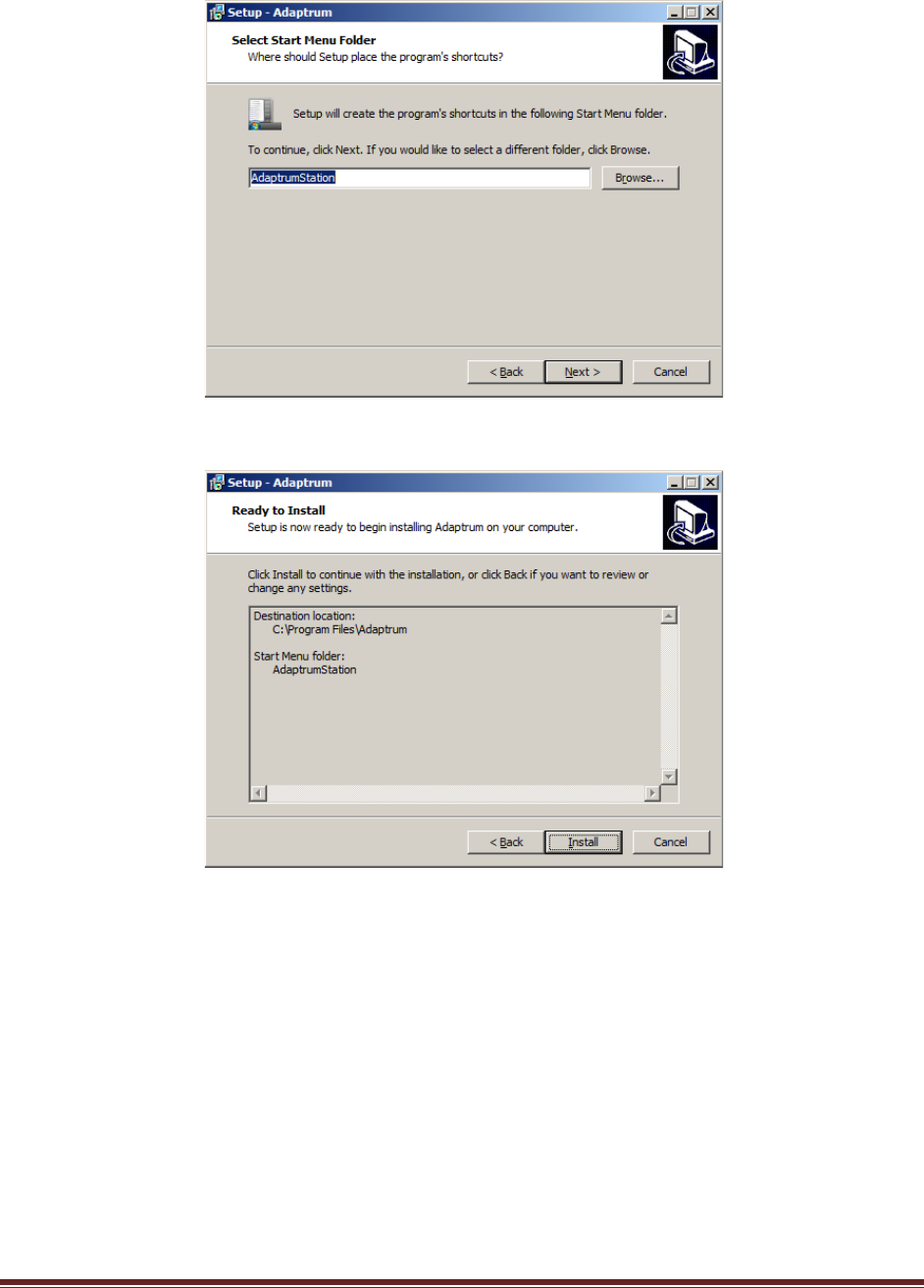
2) Select the desired installation directory and click “Next”. The default is “C:\Program
Files\Adaptrum”
3) Select a folder in the Start Menu to place the program executable shortcut and click “Next”. The
default is “AdaptrumStation” for the base station installation.
8
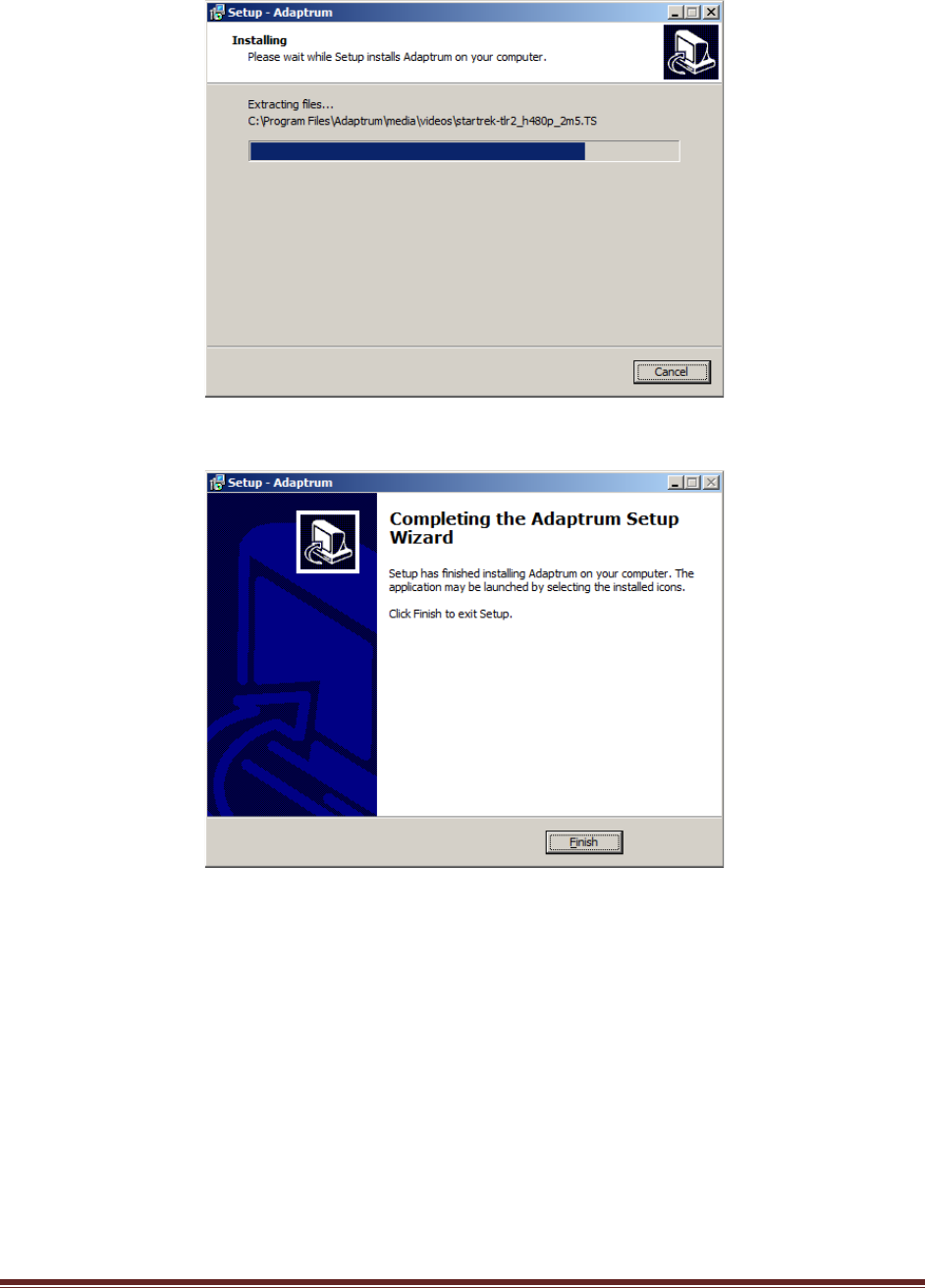
4) Double check the folder selections and click “Install” to install the program.
5) The installation progress window will show.
9
6) Once the installation is complete, click “Finish”.
The software installation on the client station follows the same steps except the default “Start Menu”
folder for the client station is “AdaptrumClient”.
If an installed radio unit and control PC are redeployed at a differently location, the installer
must uninstall the old software and reinstall the software on the control PC.
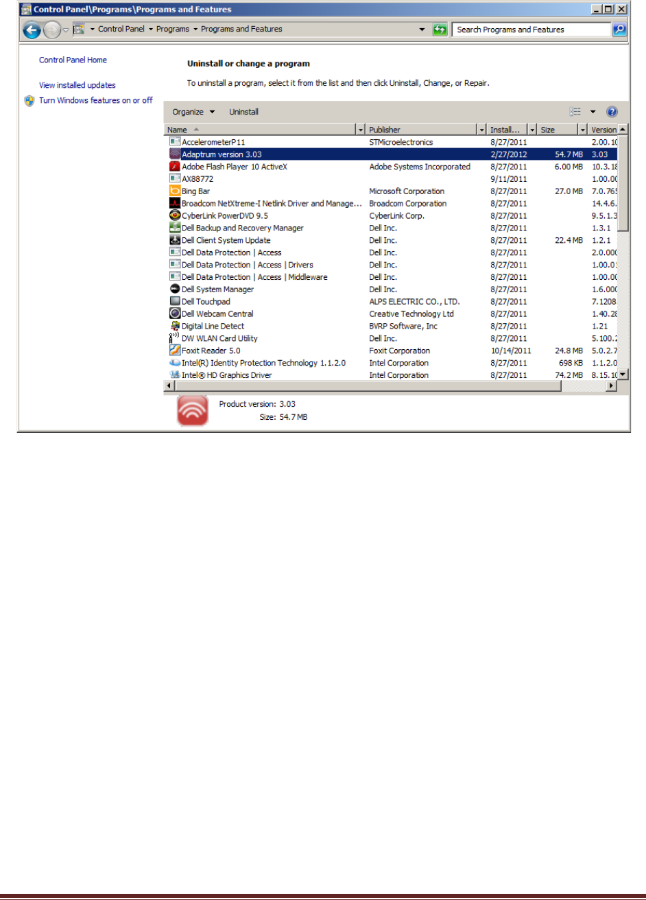
To uninstall the software, Use “Start” “Control Panel” “Uninstall a program” under
“Programs”. The following window will show. Right click “Adaptrum version 3.03” to uninstall the
program.
10
11
Post-Installation Setup
The installer needs to perform the following steps to complete the system installation.
Base Station Setup
On the base station control PC:
1) Launch the “Adaptrum” software in “Start/AdaptrumStation/Adaptrum”. The software will start
in the “Installer” mode where the installer can enter registration information and channel list
request.
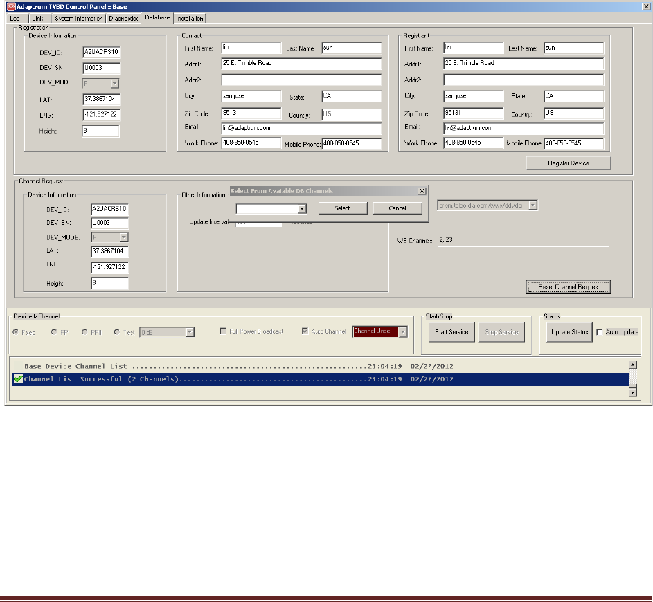
2) As shown in the following figure, enter the correct registration information and click “Register
Device” on the “Database” pane to register device. Then enter the correct channel list
information and click “Reset Channel List” to request a channel list. Note that the system starts
with an undefined channel, the software will prompt for channel selection. Note that the
software currently works with Telcordia TV Whitespace Database.
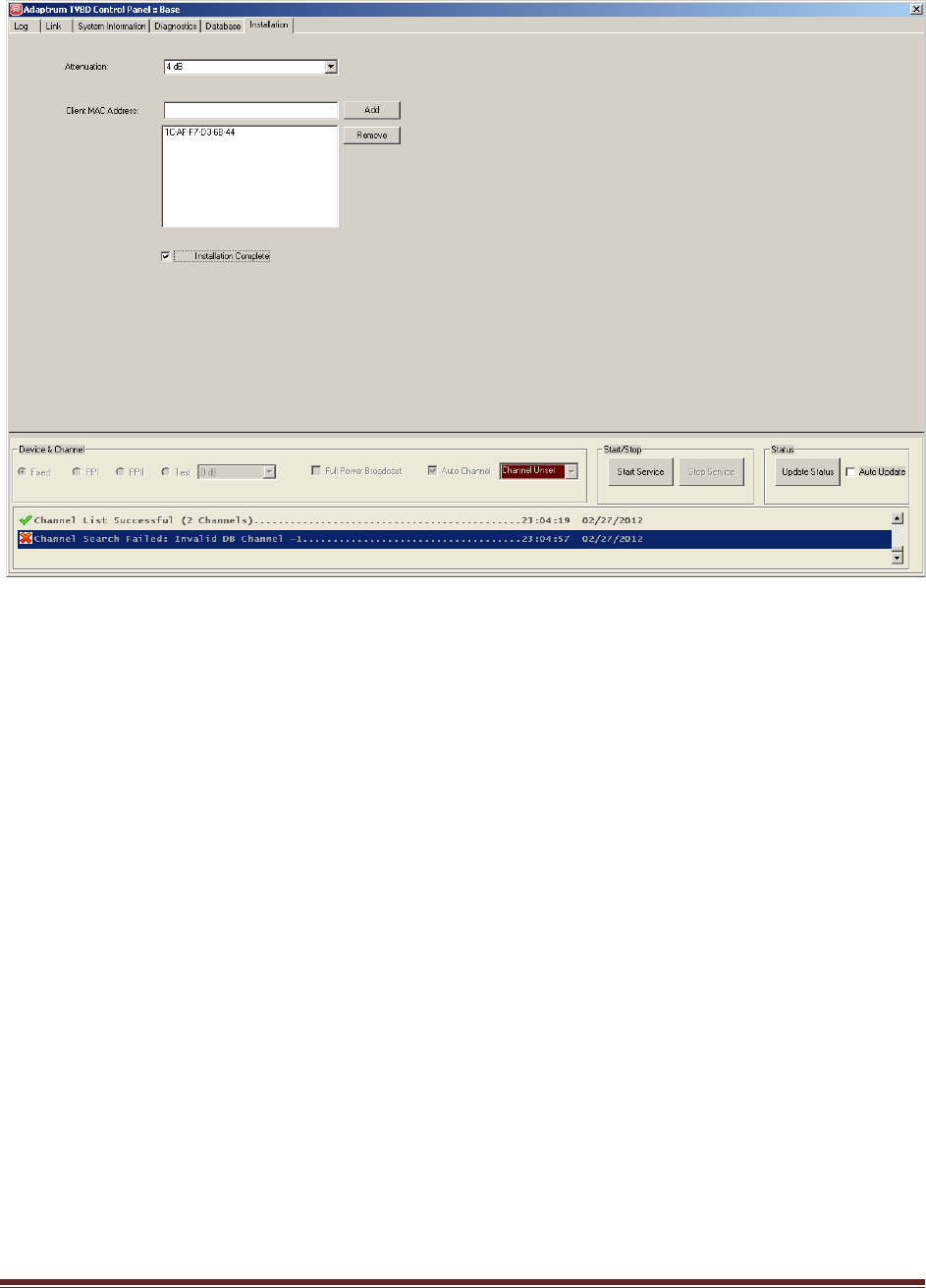
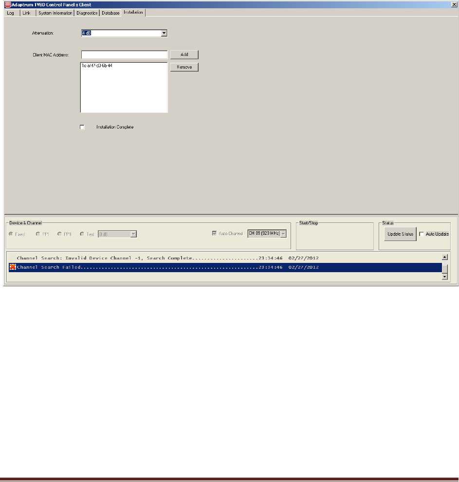
3) Go to the “Installation” pane and enter the correct output attenuation level as discussed in
Section “Hardware Installation” and enter the client side MAC addresses as shown in the
following figure. All devices that will connect to the client station should be entered.
12
4) Check the “Installation Complete” checkbox as shown above. This will save all the installation
information including: device registration information, channel list information, output
attenuation level and client MAC addresses, to the system registry. The next time the software
will launch in the “User” mode where all the installation options will be loaded directly from the
system registry and cannot be altered.
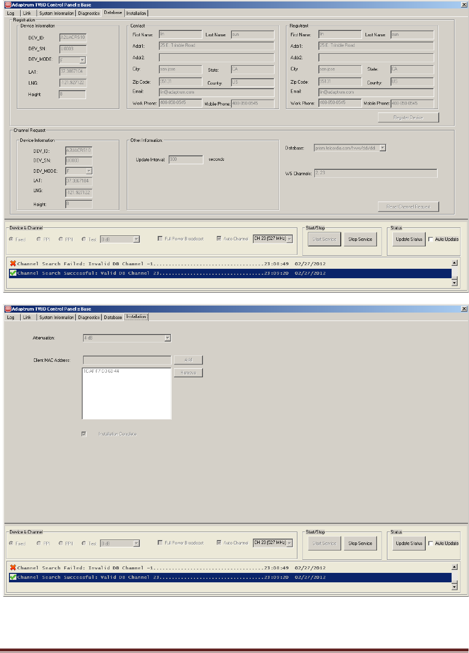
5) Restart the software and it should launch in the “User” mode as shown in the following figures
where the installation options are loaded from system registry and disabled.
13
6) Follow the instructions in the “ACRS 1.0 User Manual” to select a channel for base station
operation.
14
Client Station Setup
The following steps should be followed on the client station to complete the installation. Note
that the following steps require an active connection to the base station.
1) Launch the “Adaptrum” software in the “Start/AdaptrumClient/Adaptrum”. The software will
start in “Installer” mode where the installer can enter registration information and channel list
request.
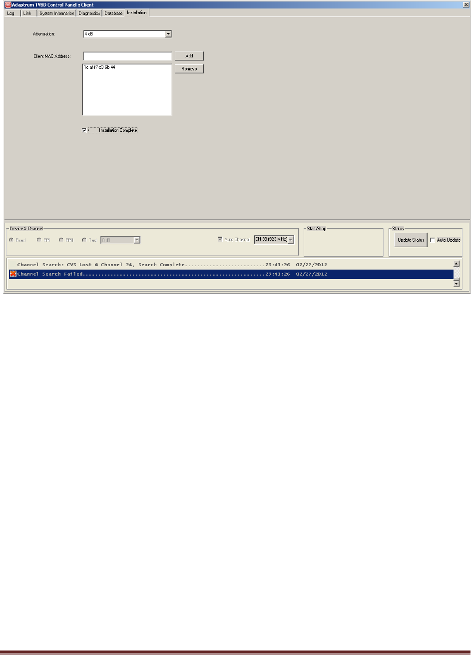
2) Go to the “Installation” pane and enter the correct output attenuation level as discussed
previously and enter the client side MAC addresses as shown in the following figure. All devices
that will connect to the client station should be entered.
15
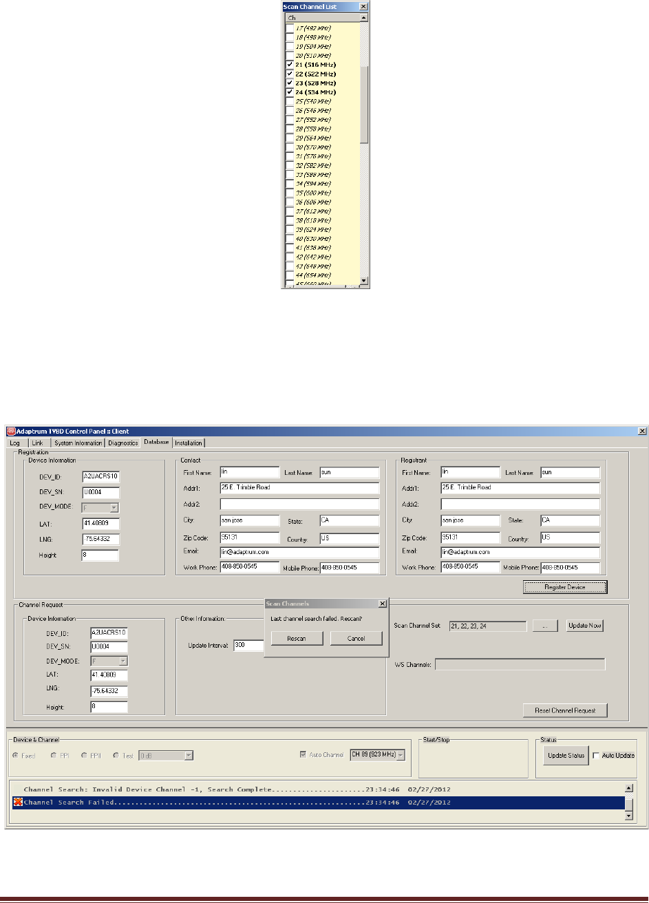
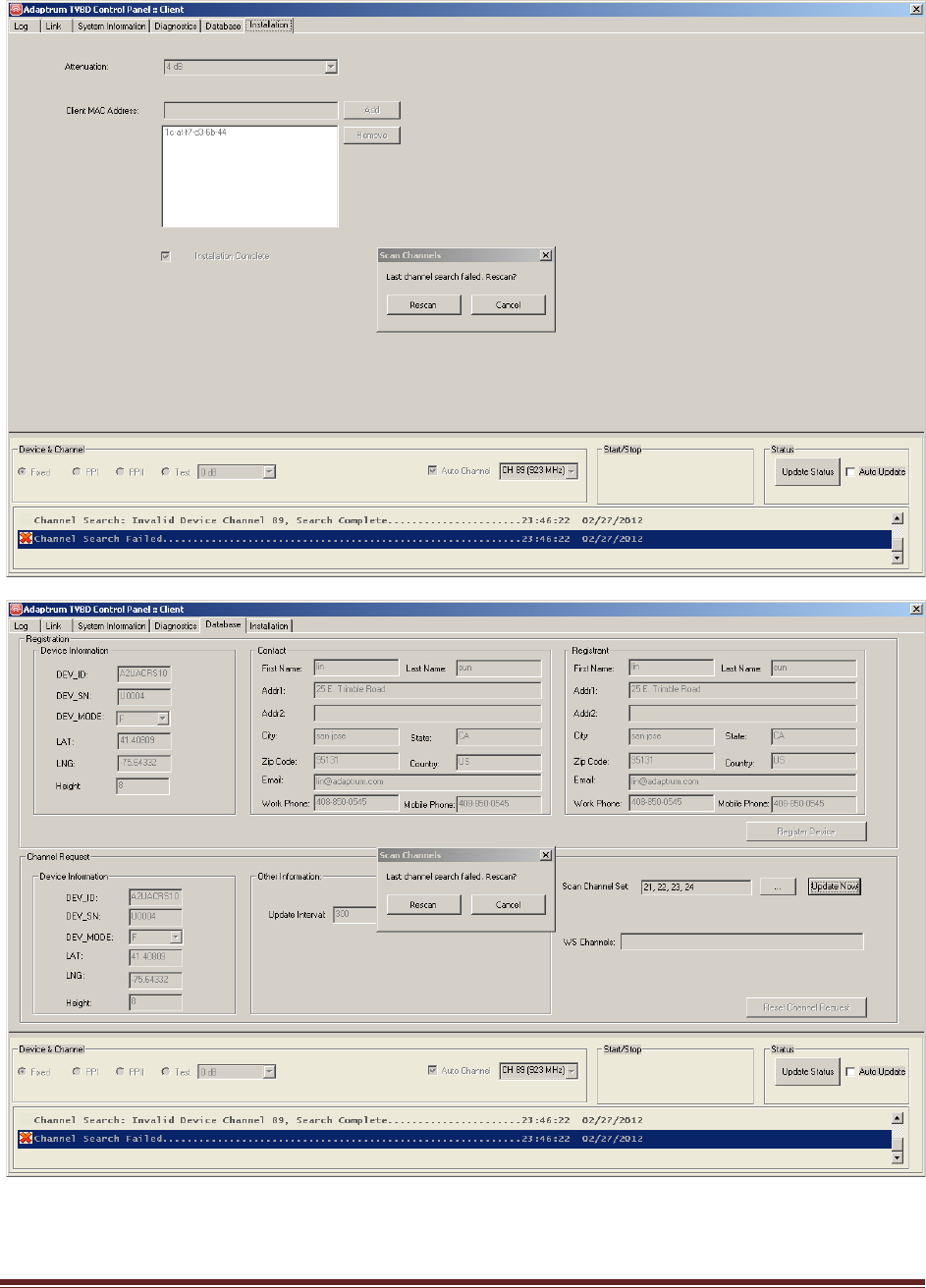
3) Go to the “Database” pane and enter the scan channel set using the “…” button right next to
“Scan Channel Set” as shown in the following figure. When “…” button is clicked, the scan
channel selection window will pop up as shown above. Select the desired channels and then
click “Update Now” to update the scan channel set. Click “Rescan” button on the “Scan
Channels” prompt to scan the channels.
16
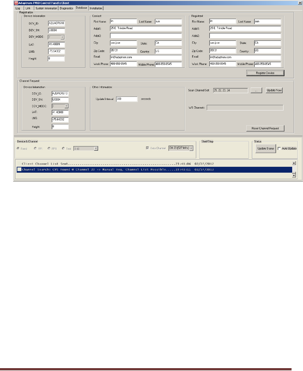
4) The scan should be in progress. When signal is detected on a particular channel, the system will
alert the installer as shown in the following figure, i.e. “Channel Search: CVS Found @ Channel
23…”
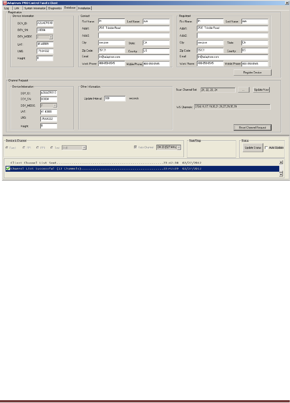
5) At this point, enter the correct registration information and click “Register Device” to register
the device. Then enter the correct channel list request information and click “Reset Channel
Request” to request a channel list. The following figure shows registration and channel list
successful.
17
6) Base on the channel list in the area, select a set of scan channels as described before. Note that
the scan channel list usually contains at least the database channel list and possibly other
channels that may be used by the base station.
7) Go to the “Installation” pane and check the “Installation Complete” checkbox and quit the
software. This will save device registration information, channel list information, scan channel
list, output attenuation level and client MAC addresses to the system registry.
18
8) The next time the software will launch in the “User” mode where these installation options will
be loaded from system registry and cannot be altered as shown in the following figures. Note
that however in the “User” mode, the user may choose a different scan channel set.
19

20
The above concludes the base station and client station installation by a professional installer. Please
refer to “ACRS 1.0 User Manual” for detailed discussion on system operation post installation.